EP4186347B1 - Selbstfahrendes arbeitsgerät - Google Patents
Selbstfahrendes arbeitsgerät Download PDFInfo
- Publication number
- EP4186347B1 EP4186347B1 EP21210473.1A EP21210473A EP4186347B1 EP 4186347 B1 EP4186347 B1 EP 4186347B1 EP 21210473 A EP21210473 A EP 21210473A EP 4186347 B1 EP4186347 B1 EP 4186347B1
- Authority
- EP
- European Patent Office
- Prior art keywords
- work implement
- implement according
- detection means
- guide
- tool
- Prior art date
- Legal status (The legal status is an assumption and is not a legal conclusion. Google has not performed a legal analysis and makes no representation as to the accuracy of the status listed.)
- Active
Links
Images




Classifications
-
- A—HUMAN NECESSITIES
- A01—AGRICULTURE; FORESTRY; ANIMAL HUSBANDRY; HUNTING; TRAPPING; FISHING
- A01D—HARVESTING; MOWING
- A01D34/00—Mowers; Mowing apparatus of harvesters
- A01D34/006—Control or measuring arrangements
- A01D34/008—Control or measuring arrangements for automated or remotely controlled operation
-
- A—HUMAN NECESSITIES
- A01—AGRICULTURE; FORESTRY; ANIMAL HUSBANDRY; HUNTING; TRAPPING; FISHING
- A01D—HARVESTING; MOWING
- A01D34/00—Mowers; Mowing apparatus of harvesters
- A01D34/01—Mowers; Mowing apparatus of harvesters characterised by features relating to the type of cutting apparatus
- A01D34/412—Mowers; Mowing apparatus of harvesters characterised by features relating to the type of cutting apparatus having rotating cutters
- A01D34/63—Mowers; Mowing apparatus of harvesters characterised by features relating to the type of cutting apparatus having rotating cutters having cutters rotating about a vertical axis
- A01D34/74—Cutting-height adjustment
-
- A—HUMAN NECESSITIES
- A01—AGRICULTURE; FORESTRY; ANIMAL HUSBANDRY; HUNTING; TRAPPING; FISHING
- A01D—HARVESTING; MOWING
- A01D34/00—Mowers; Mowing apparatus of harvesters
- A01D34/01—Mowers; Mowing apparatus of harvesters characterised by features relating to the type of cutting apparatus
- A01D34/02—Mowers; Mowing apparatus of harvesters characterised by features relating to the type of cutting apparatus having reciprocating cutters
- A01D34/30—Driving mechanisms for the cutters
-
- A—HUMAN NECESSITIES
- A01—AGRICULTURE; FORESTRY; ANIMAL HUSBANDRY; HUNTING; TRAPPING; FISHING
- A01D—HARVESTING; MOWING
- A01D69/00—Driving mechanisms or parts thereof for harvesters or mowers
- A01D69/06—Gearings
-
- A—HUMAN NECESSITIES
- A01—AGRICULTURE; FORESTRY; ANIMAL HUSBANDRY; HUNTING; TRAPPING; FISHING
- A01D—HARVESTING; MOWING
- A01D2101/00—Lawn-mowers
Definitions
- the invention relates to a self-propelled implement of the type specified in the preamble of claim 1.
- a lawnmower is known with an adjustment device for the tool, which includes a servomotor and an adjusting wheel.
- the adjusting wheel has an eccentric pin that engages in a mount for the motor.
- the invention is based on the object of creating a self-propelled implement of the generic type in which the position of the tool can be easily detected.
- a detection device for detecting the height of the tool.
- the detection device includes coding elements on an adjusting wheel and at least one detection means.
- the at least one first coding element for the first end position differs from the at least one second coding element for the second end position.
- Coding elements and detection means allow the height of the tool to be detected in a simple manner. This means that the coding elements for the first end position and differ from each other for the second end position, the end positions can be clearly detected by the at least one detection means.
- the height position of the tool can be done in a simple manner by detecting an end position and determining the position of the tool starting from this end position, for example via further coding elements.
- a simple structure and precise detection of the altitude, including the detection of the end positions, is achieved if two detection means are provided, which are arranged at a predetermined distance from one another. Because two detection means are provided, a simple design of the coding elements is possible, for example over different lengths of the coding elements in the circumferential direction. Depending on whether one detection means or both detection means detect at least one coding element, coding elements of different lengths can be easily recognized.
- the coding elements are formed by projections or the absence of projections.
- the gaps formed between the projections are detected by the at least one detection means in the same way as the projections.
- Simple coding is possible by appropriately arranging the projections and the gaps between the projections.
- the detection means are optical detection means.
- Optical detection means are, in particular, laser light sources and suitable associated receivers.
- other types of detection means for example magnetic detection means such as Hall sensors that interact with magnets, mechanical switches, electrical contacts, for example sliding contacts and associated actuating elements can also be advantageous.
- the magnets, actuating elements or the like form the coding elements.
- the adjusting wheel and the at least one detection means are firmly connected to a one-piece guide part.
- the adjusting wheel is advantageously mounted directly in the guide part.
- the detection means are advantageously fixed to a common component, the position of which can be adjusted relative to the guide part to compensate for tolerances. This means that manufacturing tolerances between the adjusting wheel and the detection means are easily minimized. This makes it possible to accurately record the height of the tool.
- the adjusting device advantageously comprises a worm wheel driven by the servomotor.
- the worm wheel is preferably mounted on the guide part.
- the worm wheel preferably engages with the adjusting wheel.
- the worm wheel and adjusting wheel therefore form a single-stage gearbox.
- a multi-stage gear can also be provided, which transmits the rotational movement of the worm wheel to the adjusting wheel.
- the adjusting wheel is designed as a spur wheel.
- the drive motor is advantageously guided on the chassis via at least one, in particular two, linear guides.
- a linear guide preferably allows the drive motor to move relative to the chassis transversely to the longitudinal direction of the linear guide.
- This linear guide is therefore designed as a floating bearing.
- the movement of the drive motor relative to the chassis transversely to the longitudinal direction of the linear guide can be provided, for example, to compensate for manufacturing tolerances or to compensate for changes in length of the components under the influence of temperature.
- the other linear guide is preferably designed as a fixed bearing and does not allow the drive motor to move relative to the chassis transversely to the longitudinal direction of the linear guide.
- the drive motor is advantageously arranged in a motor holder.
- the motor mount can, for example, have a receiving pot that is open at the top and in which the drive motor is arranged.
- a simple design results when the motor mount has an elastic section that is supported on the linear guide.
- the elastic section advantageously deforms when the motor mount moves relative to the chassis transversely to the longitudinal direction of the linear guide. If the motor mount moves relative to the chassis transversely to the longitudinal direction of the linear guide, the elastic section absorbs this transverse movement by deformation. Such a movement transverse to the longitudinal direction of the linear guide can arise, for example, due to changes in length caused by temperature changes.
- the elastic section is in particular formed in one piece on the motor mount.
- the elastic section is particularly advantageously formed by correspondingly thin-walled design of areas of the motor mount. This results in a simple structure with few individual parts.
- the linear guide is advantageously designed on the guide part.
- the axis of rotation of the adjusting wheel preferably runs perpendicular to the adjustment direction of the adjusting device.
- the adjusting wheel is coupled to the drive motor in particular at a distance from its axis of rotation. Due to the coupling at a distance from the axis of rotation, an adjustment of the position of the drive motor and thus the position of the tool is possible via an eccentric pin or the like. This results in a simple structure and an advantageous adjustment.
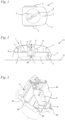
- Fig. 1 shows a lawn mower 1 in a schematic representation as an exemplary embodiment of a self-propelled implement.
- the self-propelled work device can also be another work device.
- the lawn mower 1 has a hood 2 which covers the tool of the lawn mower 1, in the exemplary embodiment a knife 4 shown schematically.
- the lawn mower 1 also has several wheels 3 with which the lawn mower 1 can be moved over the ground.
- Fig. 2 shows a schematic section through the lawn mower 1.
- the lawn mower 1 is in a parking position 13. In the parking position 13, the lawn mower 1 is parked on a flat, horizontal parking surface 12.
- the wheels 3 of the lawn mower 1 are on the ground.
- the lawn mower 1 has two rear, laterally arranged wheels 3 with a large diameter and a front, centrally arranged, small wheel 3.
- the front wheel 3 is arranged under the hood 2 in the exemplary embodiment.
- the lawn mower 1 has a chassis 6 on which the wheels 3 and the hood 2 are fixed.
- the hood 2 is supported on the chassis 6 via bearings 11.
- the hood 2 is advantageously arranged to have limited movement relative to the chassis 6.
- Fig. 2 shows, the knife 4 is arranged on a drive shaft 7 of a drive motor 8. During operation, the knife 4 is driven to rotate about an axis of rotation 64 by the drive motor 8.
- the drive motor 8 is an electric motor in the exemplary embodiment.
- the drive motor 8 is arranged in a motor holder 9.
- the drive motor 8 is fixed to the motor mount 9 so that the drive motor 8 can be moved with the motor mount 9 relative to the chassis 6.
- the motor mount 9 is opposite the chassis 6 via one Adjusting device 10 adjustable in a vertical direction 14.
- the vertical direction 14 is the direction that runs vertically in the storage position 13. During the adjustment process, the motor mount 9 moves at least partially in the vertical direction 14, so that the height of the knife 4 relative to the ground can be adjusted.
- the adjustment direction can also be inclined to the vertical direction 14.
- a controller 5 is provided to control the drive motor 8 and the adjusting device 10. In the exemplary embodiment, the controller 5 is arranged on the chassis 6. However, an arrangement on the motor mount 9 can also be advantageous.
- Fig. 3 shows in perspective the drive motor 8 and the motor holder 9 as well as the adjusting device 10.
- the adjusting device 10 comprises a guide part 20 which is firmly connected to the chassis 6 ( Fig. 2 ) connected is.
- fastening openings 49 are provided in the foot area of the guide part 20.
- the guide part 20 comprises a receiving section 48 in which the motor holder 9 is movably arranged.
- the motor mount 9 is in the in Fig. 4 shown vertical direction 14 movable.
- the Figures 3 to 10 show the motor mount 9 and the drive motor 8 in a first, lower end position 30.
- the adjusting device 10 is arranged on one side of the motor holder 9 on the guide part 20.
- the adjusting device 10 comprises a servomotor 15.
- the servomotor 15 drives an in Fig. 7 worm wheel 16 shown.
- the axis of rotation 17 of the worm wheel 16 is arranged perpendicular to the axis of rotation 50 of the drive motor 8 in the exemplary embodiment.
- the axis of rotation 50 of the drive motor 8 coincides with the axis of rotation 64 of the knife 4.
- parking position 13 Fig. 2
- the axis of rotation 17 of the worm wheel 16 is horizontal.
- the adjusting device 10 includes an adjusting wheel 18, which is rotatably mounted about an axis of rotation 19.
- the axis of rotation 19 is arranged perpendicular to the axis of rotation 17 of the worm wheel 16 in the exemplary embodiment.
- the axis of rotation 19 lies horizontally in the parking position 13.
- the adjusting wheel 18 is mounted on the guide part 20 in the exemplary embodiment.
- the Adjusting wheel 18 has a bearing socket 24 which is rotatably mounted on a bearing surface 21 of the guide part 20.
- the bearing surface 21 is advantageously cylindrical, and the bearing socket 24 has outwardly projecting ribs for contact with the bearing surface 21.
- the servomotor 15 and the worm wheel 16 are also mounted on the guide part 20. In the exemplary embodiment, the worm wheel 16 engages directly in the adjusting wheel 18. In an alternative embodiment, additional gear stages can also be provided.
- the adjusting wheel 18 carries an eccentric pin 34 on its side facing the motor mount 9 ( Fig. 8 ).
- the eccentric pin 34 carries a slider 35, which will be described in more detail below.
- the slider 35 is rotatably mounted on the eccentric pin 34.
- the motor mount 9 has two guide surfaces 37 and 38, between which the eccentric pin 34 with the slider 35 is arranged.
- the guide surfaces 37 and 38 form a guide 36 with the slider 35. In the storage position 13, the guide 36 is aligned horizontally. However, a different orientation of the guide 36 can also be advantageous.
- the eccentric pin 34 moves in the vertical direction 14 and thereby causes a movement of the guide part 20 in the vertical direction 14.
- the movement of the eccentric pin in the horizontal direction i.e. perpendicular to the vertical direction 14, caused by the rotation of the adjusting wheel 18, causes a displacement of the slider 35 relative to the guide surfaces 37 and 38.
- the eccentric pin 34 rotates in the slider 35.
- a detection device 32 comprises at least one detection means 25.
- two detection means 25 are provided, such as Fig. 10 shows.
- the detection means 25 are designed to detect coding elements 26, 27, 28, 29 when they move past the at least one detection means 25.
- the detection means 25 are optical detection means, for example light barriers Laser light, trained.
- the coding elements 26 and 27 are formed by projections on the adjusting wheel 18.
- the coding elements 28 and 29 are formed by missing projections.
- the coding element 29 is in Fig. 10 shown. How Fig. 10 also shows, the coding elements 26 to 29 are arranged on a circular path around the axis of rotation 19. When the adjusting wheel 18 rotates, the coding elements 26 to 29 move past the detection means 25 and are detected. This allows the rotational position of the adjusting wheel 18 and thus the height of the guide part 20, the drive motor 8 and the knife 4 to be determined.
- the worm wheel 16 is mounted in a bearing surface 22 of the guide part 20.
- the bearing surface 22 is preferably designed as a hollow cylinder.
- all elements of the adjustment device 10 except for the control 5 ( Fig. 2 ) and the detection means 25 are stored directly on the guide part 20.
- the guide part 20 is closed by a cover 51.
- the detection means 25 are held on the cover 51.
- the cover 51 is fixed to the guide part 20 in the exemplary embodiment via at least one screw 70.
- the screw 70 is guided in the cover 51 with little play, so that small tolerances can be compensated for when positioning the cover 51 on the guide part 20.
- a different arrangement of the detection means 25, in particular on the guide part 20, can also be advantageous.
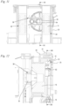
- Fig. 8 shows the mounting of the motor holder 9 on the guide part 20.
- the motor holder 9 and the guide part 20 form two linear guides 44 and 45.
- the longitudinal direction 46 of the linear guides 44 and 45 is aligned in the vertical direction 14 in the storage position 13.
- the linear guides 44 and 45 each have a guide piece 52 which projects between the opposing slideways 53 of each linear guide 44, 45 and is guided between them.
- the first linear guide 44 is designed as a fixed bearing and the second linear guide 45 as a floating bearing.
- the first linear guide 44 does not allow any movement of the motor holder 9 relative to the guide 20 in the direction perpendicular to the longitudinal direction 46.
- the guide piece 52 is advantageously guided without play between the slideways 53 within the framework of the manufacturing tolerances.
- the second linear guide 45 has elastic sections 47, on which the guide piece 52 of the motor holder 9, which projects between the opposing slideways 53 of the linear guide 45, can deform.
- the elastic sections 47 thereby allow a relative movement of the guide part 20 relative to the slideways 53 perpendicular to the longitudinal direction 46.
- the Figures 8 and 9 also show the eccentric pin 34 with the slider 35 and the guide 36.
- the eccentric pin 34 is designed as a hollow pin in the exemplary embodiment.
- the eccentric pin 34 has a central axis 43.
- the axis of rotation 19 of the adjusting wheel 18 is at a distance f from the central axis 43 of the eccentric pin 34.
- the path that the knife 4 travels between the upper end position 31 and the lower end position 30 is advantageously less than twice the distance f, in particular less than 1.8 times the distance f.
- the slider 35 is designed to be mirror-symmetrical to a first plane of symmetry 54 located between the guides 37 and 38.
- the first plane of symmetry 54 is aligned in the longitudinal direction 42 of the guide 36.
- the slider 35 is also designed symmetrically to a second plane of symmetry 55, which runs perpendicular to the first plane of symmetry 54 and through the central axis 43.
- the slider 35 has at least one sliding surface 39, 40. With the at least one sliding surface 39, 40, the slider 35 rests on at least one guide surface 37, 38.
- two sliding surfaces 39, 40 are provided on each guide surface 37 and 38.
- the sliding surfaces 39 have an outer side 56 which is remote from the other sliding surface 40 resting on this guide surface 37, 38.
- the sliding surfaces 40 have an outer side 57 that is remote from the other sliding surface 39.
- the outer sides 56, 57 are at a distance e from one another.
- the guide surfaces 37 and 38 are parallel to each other aligned and have a distance a from each other.
- the distance a can be a few centimeters, for example.
- the distance e is advantageously at least 50%, in particular at least 80%, of the distance a between the guide surfaces 37 and 38. This prevents the slider 35 from tilting or tilting between the guide surfaces 37 and 38.
- the slider 35 has a hub 59 which surrounds the eccentric pin 34.
- a plain bearing is formed between the hub 59 and the eccentric pin 34.
- Two arms 58 extend from the hub 59 in the direction of each guide surface 37 and 38.
- the arms 58 are designed to be elastic, so that the sliding surfaces 39 and 40 rest against the guide surfaces 37 and 38 in an elastically prestressed manner.
- the arms 58 have a central axis 60 which is very flat relative to the guide surfaces 37 and 38.
- the central axis 60 advantageously encloses an angle ⁇ of less than 30°, in particular of less than 20°, with an associated guide surface 37, 38.
- the sliding surfaces 39 and 40 advantageously have a distance b measured parallel to the guide surfaces 37 and 38.
- the distance b between the two sliding surfaces 39 and 40 is advantageously at least 30%, in particular at least 50%, of the distance a between the guide surfaces 37 and 38.
- At least one stop 41 is provided which limits the deformation of an arm 58.
- a stop 41 is advantageously provided adjacent to each arm 58.
- a stop 41 is provided on each guide surface 37 and 38, which protrudes between two sliding surfaces 39 and 40. In the in Fig. 9 In the unloaded state shown, the stop 41 is at a distance d from the associated guide surface 37, 38. If the worm wheel 16 is rotated and the eccentric pin 34 is thereby moved, the stop 41, which is at the front in the direction of movement of the eccentric pin 34, can be on the assigned one Hit the guide surface 37, 38 to ensure good transmission of the actuating movement.
- the stop 41 is arranged between the sliding surfaces 39 and 40.
- the sliding surfaces 39 and 40 have a distance c from the central axis 43 of the eccentric pin 34, which is measured parallel to the guide surfaces 37 and 38. In the exemplary embodiment, the distance c is larger than the radius of the eccentric pin 34. In the exemplary embodiment, all sliding surfaces 39, 40 of the slider 35 have the same distance from the central axis 43 of the eccentric pin 34, measured in the longitudinal direction 42 of the guide 36.
- the adjusting wheel 18 carries the coding elements 26 to 29 arranged in a circle around the axis of rotation 19.
- the coding elements 26 and 27 are designed as projections.
- Each detection means 25 has a transmitter 61 and a receiver 62. The arrangement of the transmitters 61 and receivers 62 can also be reversed.
- the detection means 25 are optical detection means, and the transmitters 61 emit light, in particular laser light, and the receivers 62 receive the light and evaluate the received light intensity. If a projection of a coding element 26 or 27 comes between the transmitter 61 and the receiver 62 of a detection means 25, the receiver 62 is covered and the signal received by the transmitter 61 is weakened.
- the detection means 25 are optical detection means.
- the detection means 25 can also be other types of detection means 25, for example magnetic detection means 25 such as Hall sensors, which interact with magnets forming the coding elements, mechanical switches or electrical contacts, for example sliding contacts or the like.
- the two detection means 25 are arranged at an angular distance ⁇ from one another.
- the angular distance ⁇ is greater than the circumferential angle over which a coding element 26 or 28 extends.
- the angular distance ⁇ is measured between the central axes of the detection means 25.
- the coding elements 28 are due to a missing projection, i.e. the gap between two successive coding elements 26 educated.
- the coding elements 26 and 28 each extend over an angle y, which can be, for example, 1.5 times the angular distance ⁇ .
- the angular distance ⁇ and the angle ⁇ are preferably coordinated with one another in such a way that in an area between the end positions 30 ( Fig. 7 ) and 31 ( Fig. 14 ) of the knife 4 in each position only one of the detection means 25 is covered by a coding element 26.
- a coding element 29 is arranged in the area of one of the detection means 25.
- the coding element 29 extends over an angular distance that corresponds at least to the angle ⁇ .
- the coding element 29 is a missing projection in the exemplary embodiment. If both receivers 62 of the detection means 25 receive a signal that is not attenuated, the motor mount 9 is therefore in its first, lower end position 30.
- the motor mount 9 moves from the lower end position 30 towards its upper end position 31 ( Figures 14 to 16 ), the coding elements 26 and 27 move past the detection means 25.
- the receivers 62 are partially covered by the coding elements 26 in every position, so that the received signal is weaker than in the first, lower end position 30.
- the changing signal strength can be evaluated by the controller 5.
- the position of the motor holder 9 can be determined starting from an end position 30, 31. Due to the eccentric pin 34, which changes in the vertical direction 14 non-linearly to the adjustment angle of the adjusting wheel 18, there is a non-linear relationship between the number of coding elements 26, 27 guided past the detection means 25 and the distance covered by the motor holder 9 and the knife 4.
- the arrangement is shown in a middle position of the motor holder 9 and the knife 4.
- the eccentric pin 34 has moved from the lower end position 30 to the middle position relative to the guide surfaces 37 and 38 from one horizontal end position to the other. From the middle layer to the top End position 31, the eccentric pin 34 moves back to its starting position.
- the slider 35 is in the first end position 30 and the second end position 31 in the same position relative to the guide surfaces 37 and 38.
- Fig. 14 shows the motor holder 9 in its second, upper end position 31.
- a coding element 27 is arranged in the area of the detection means 25.
- the coding element 27 for the second, upper end position 31 differs from the coding element 29 for the first, lower end position 30.
- the coding elements 27 and 29 also differ from the coding elements 26 and 28 for positions between the end positions 30 and 31.
- Fig. 16 shows the arrangement of the coding element 27 in the area of the detection means 25. How Fig. 16 shows, both receivers 62 of the detection means 25 are at least partially covered by the coding element 27. This means that the second, upper end position 31 can be clearly recognized by the controller 50.
- the slider 35 has moved from the lower end position 30 to the upper end position 31 in the direction of the second linear guide 44 and back.
Landscapes
- Life Sciences & Earth Sciences (AREA)
- Environmental Sciences (AREA)
- Harvester Elements (AREA)
- Connection Of Motors, Electrical Generators, Mechanical Devices, And The Like (AREA)
Description
- Die Erfindung betrifft ein selbstfahrendes Arbeitsgerät der im Oberbegriff des Anspruchs 1 angegebenen Gattung.
- Aus der
CN 107 996 124 A ist ein Rasenmäher mit einer Einstellvorrichtung für das Werkzeug bekannt, die einen Stellmotor und ein Stellrad umfasst. Das Stellrad weist einen Exzenterzapfen auf, der in eine Aufnahme für den Motor eingreift. - Der Erfindung liegt die Aufgabe zugrunde, ein selbstfahrendes Arbeitsgerät der gattungsgemäßen Art zu schaffen, bei dem die Position des Werkzeugs einfach erfassbar ist.
- Diese Aufgabe wird durch ein selbstfahrendes Arbeitsgerät mit den Merkmalen des Anspruchs 1 gelöst.
- Erfindungsgemäß ist eine Erfassungseinrichtung zur Erfassung der Höhenlage des Werkzeugs vorgesehen. Die Erfassungseinrichtung umfasst Kodierelemente an einem Stellrad und mindestens ein Erfassungsmittel. Das mindestens eine erste Kodierelement für die erste Endlage unterscheidet sich dabei von dem mindestens einen zweiten Kodierelement für die zweite Endlage.
- Kodierelemente und Erfassungsmittel lassen auf einfache Weise eine Erfassung der Höhenlage des Werkzeugs zu. Dadurch, dass sich die Kodierelemente für die erste Endlage und für die zweite Endlage voneinander unterscheiden, können die Endlagen eindeutig von dem mindestens einen Erfassungsmittel erfasst werden. Die Höhenlage des Werkzeugs kann auf einfache Weise durch Erkennung einer Endlage und Ermittlung der Position des Werkzeugs ausgehend von dieser Endlage, beispielsweise über weitere Kodierelemente, erfolgen.
- Ein einfacher Aufbau und eine genaue Erkennung der Höhenlage einschließlich der Erkennung der Endlagen wird erreicht, wenn zwei Erfassungsmittel vorgesehen sind, die in vorgegebenem Abstand zueinander angeordnet sind. Dadurch, dass zwei Erfassungsmittel vorgesehen sind, ist eine einfache Ausbildung der Kodierelemente, beispielsweise über unterschiedliche Längen der Kodierelemente in Umfangsrichtung, möglich. In Abhängigkeit davon, ob ein Erfassungsmittel oder beide Erfassungsmittel mindestens ein Kodierelement erfassen, können Kodierelemente unterschiedlicher Längen auf einfache Weise erkannt werden.
- In einfacher Gestaltung sind die Kodierelemente durch Vorsprünge oder das Fehlen von Vorsprüngen gebildet. Die zwischen den Vorsprüngen gebildeten Lücken werden von dem mindestens einen Erfassungsmittel ebenso erfasst wie die Vorsprünge. Durch geeignete Anordnung der Vorsprünge und der Lücken zwischen den Vorsprüngen ist eine einfache Kodierung möglich.
- In einfacher Gestaltung sind die Erfassungsmittel optische Erfassungsmittel. Optische Erfassungsmittel sind insbesondere Laserlichtquellen sowie geeignete zugeordnete Empfänger. Auch andere Arten von Erfassungsmitteln, beispielsweise magnetische Erfassungsmittel wie Hallsensoren, die mit Magneten zusammenwirken, mechanische Schalter, elektrische Kontakte, beispielsweise Schleifkontakte und zugeordnete Betätigungselemente können jedoch vorteilhaft sein. Die Magnete, Betätigungselemente oder dgl. bilden dabei die Kodierelemente.
- Um eine genaue Positionierung von Stellrad und Erfassungsmittel zu erreichen, ist vorteilhaft vorgesehen, dass das Stellrad und das mindestens eine Erfassungsmittel fest mit einem einteilig ausgebildeten Führungsteil verbunden sind. Vorteilhaft ist das Stellrad unmittelbar in dem Führungsteil gelagert. Die Erfassungsmittel sind vorteilhaft an einem gemeinsamen Bauteil fixiert, dessen Position gegenüber dem Führungsteil zum Ausgleich von Toleranzen einstellbar ist. Dadurch werden Fertigungstoleranzen zwischen Stellrad und Erfassungsmittel auf einfache Weise minimiert. Dadurch wird eine genaue Erfassung der Höhenlage des Werkzeugs ermöglicht.
- Vorteilhaft umfasst die Einstellvorrichtung ein von dem Stellmotor angetriebenes Schneckenrad. Das Schneckenrad ist bevorzugt an dem Führungsteil gelagert. Auch eine andere Anordnung des Schneckenrads kann jedoch vorteilhaft sein. Das Schneckenrad greift bevorzugt in das Stellrad ein. Schneckenrad und Stellrad bilden demnach ein einstufiges Getriebe. In alternativer Ausführung kann auch ein mehrstufiges Getriebe vorgesehen sein, das die Drehbewegung des Schneckenrads auf das Stellrad überträgt. In bevorzugter Gestaltung ist das Stellrad als Stirnrad ausgebildet.
- Der Antriebsmotor ist an dem Chassis vorteilhaft über mindestens eine, insbesondere über zwei Linearführungen geführt. Dadurch wird ein Verkippen des Antriebsmotors gegenüber dem Chassis verhindert. Bevorzugt lässt eine Linearführung eine Bewegung des Antriebsmotors gegenüber dem Chassis quer zur Längsrichtung der Linearführung zu. Diese Linearführung ist demnach als Loslager ausgebildet. Die Bewegung des Antriebsmotors gegenüber dem Chassis quer zur Längsrichtung der Linearführung kann beispielsweise zum Ausgleich von Fertigungstoleranzen oder zum Ausgleich von Längenänderungen der Bauteile unter Temperatureinfluss vorgesehen sein. Die andere Linearführung ist bevorzugt als Festlager ausgebildet und lässt keine Bewegung des Antriebsmotors gegenüber dem Chassis quer zur Längsrichtung der Linearführung zu.
- Der Antriebsmotor ist vorteilhaft in einer Motoraufnahme angeordnet. Die Motoraufnahme kann beispielsweise einen nach oben offenen Aufnahmetopf aufweisen, in dem der Antriebsmotor angeordnet ist. Eine einfache Ausführung ergibt sich, wenn die Motoraufnahme einen elastischen Abschnitt aufweist, der sich an der Linearführung abstützt. Vorteilhaft verformt sich der elastische Abschnitt bei einer Bewegung der Motoraufnahme gegenüber dem Chassis quer zur Längsrichtung der Linearführung. Führt die Motoraufnahme eine Bewegung gegenüber dem Chassis quer zur Längsrichtung der Linearführung aus, so nimmt der elastische Abschnitt diese Querbewegung durch Verformung auf. Eine solche Bewegung quer zur Längsrichtung der Linearführung kann sich beispielsweise aufgrund von Längenänderungen durch Temperaturänderungen ergeben. Der elastische Abschnitt ist insbesondere einteilig an der Motoraufnahme ausgebildet. Besonders vorteilhaft ist der elastische Abschnitt durch entsprechend dünnwandige Gestaltung von Bereichen der Motoraufnahme gebildet. Dadurch wird ein einfacher Aufbau mit wenigen Einzelteilen erreicht. Die Linearführung ist vorteilhaft an dem Führungsteil ausgebildet.
- Die Drehachse des Stellrads verläuft bevorzugt senkrecht zur Verstellrichtung der Einstellvorrichtung. Das Stellrad ist insbesondere in einem Abstand zu seiner Drehachse mit dem Antriebsmotor gekoppelt. Aufgrund der Kopplung in einem Abstand zur Drehachse ist eine Verstellung der Position des Antriebsmotors und damit der Position des Werkzeugs über einen Exzenterzapfen oder dergleichen möglich. Dadurch wird ein einfacher Aufbau und eine vorteilhafte Verstellung erreicht.
- Ein Ausführungsbeispiel der Erfindung wird im Folgenden anhand der Zeichnung erläutert. Es zeigen:
- Fig. 1
- eine schematische Darstellung eines selbstfahrenden Rasenmähers in Draufsicht,
- Fig. 2
- einen schematischen Längsschnitt des Rasenmähers aus
Fig. 1 , - Fig. 3
- eine perspektivische Darstellung von Antriebsmotor, Motoraufnahme und Einstellvorrichtung in einer unteren Endlage der Motoraufnahme,
- Fig. 4
- eine Seitenansicht der Anordnung aus
Fig. 3 , - Fig. 5
- eine Draufsicht in Richtung des Pfeils V in
Fig. 4 , - Fig. 6
- eine Seitenansicht in Richtung des Pfeils VI in
Fig. 5 , - Fig. 7
- einen Schnitt entlang der Linie VII-VII in
Fig. 6 , - Fig. 8
- einen Schnitt entlang der Linie VIII-VIII in
Fig. 7 , - Fig. 9
- den Bereich des Gleitstücks und der Führung aus
Fig. 8 in vergrößerter Darstellung, - Fig. 10
- einen Schnitt entlang der Linie X-X in
Fig. 7 , - Fig. 11
- eine Schnittdarstellung entsprechend
Fig. 8 in mittlerer Position der Motoraufnahme, - Fig. 12
- einen Schnitt entlang der Linie XII-XII in
Fig. 11 , - Fig. 13
- einen Schnitt entlang der Linie XIII-XIII in
Fig. 12 , - Fig. 14
- eine Schnittdarstellung entsprechend
Fig. 8 in oberster Endlage der Motoraufnahme, - Fig. 15
- einen Schnitt entlang der Linie XV-XV in
Fig. 14 , - Fig. 16
- einen Schnitt entlang der Linie XVI-XVI in
Fig. 14 . -
Fig. 1 zeigt als Ausführungsbeispiel für ein selbstfahrendes Arbeitsgerät einen Rasenmäher 1 in schematischer Darstellung. Das selbstfahrende Arbeitsgerät kann jedoch auch ein anderes Arbeitsgerät sein. Der Rasenmäher 1 weist eine Haube 2 auf, die das Werkzeug des Rasenmähers 1, im Ausführungsbeispiel ein schematisch dargestelltes Messer 4, abdeckt. Der Rasenmäher 1 weist außerdem mehrere Räder 3 auf, mit denen der Rasenmäher 1 über den Boden bewegt werden kann. -
Fig. 2 zeigt einen schematischen Schnitt durch den Rasenmäher 1. Der Rasenmäher 1 befindet sich in einer Abstellposition 13. In Abstellposition 13 ist der Rasenmäher 1 auf einer ebenen, horizontalen Abstellfläche 12 abgestellt. Die Räder 3 des Rasenmähers 1 stehen dabei auf dem Boden. Im Ausführungsbeispiel weist der Rasenmäher 1 zwei hintere, seitlich angeordnete Räder 3 mit großem Durchmesser sowie ein vorderes, mittig angeordnetes, kleines Rad 3 auf. Das vordere Rad 3 ist im Ausführungsbeispiel unter der Haube 2 angeordnet. - Der Rasenmäher 1 weist ein Chassis 6 auf, an dem die Räder 3 und die Haube 2 fixiert sind. Die Haube 2 stützt sich über Lagerungen 11 an dem Chassis 6 ab. Die Haube 2 ist dabei vorteilhaft begrenzt beweglich gegenüber dem Chassis 6 angeordnet.
- Wie
Fig. 2 auch zeigt, ist das Messer 4 an einer Antriebswelle 7 eines Antriebsmotors 8 angeordnet. Das Messer 4 wird im Betrieb vom Antriebsmotor 8 um eine Drehachse 64 rotierend angetrieben. - Der Antriebsmotor 8 ist im Ausführungsbeispiel ein Elektromotor. Der Antriebsmotor 8 ist in einer Motoraufnahme 9 angeordnet. Der Antriebsmotor 8 ist an der Motoraufnahme 9 so fixiert, dass der Antriebsmotor 8 mit der Motoraufnahme 9 gegenüber dem Chassis 6 bewegbar ist. Die Motoraufnahme 9 ist gegenüber dem Chassis 6 über eine Einstellvorrichtung 10 in einer vertikalen Richtung 14 verstellbar. Die vertikale Richtung 14 ist die Richtung, die in Abstellposition 13 vertikal verläuft. Die Motoraufnahme 9 bewegt sich beim Einstellvorgang zumindest teilweise in vertikaler Richtung 14, so dass eine Einstellung der Höhenlage des Messers 4 gegenüber dem Boden möglich ist. Die Verstellrichtung kann dabei zur vertikalen Richtung 14 auch geneigt sein. Zur Ansteuerung des Antriebsmotors 8 und der Einstellvorrichtung 10 ist eine Steuerung 5 vorgesehen. Im Ausführungsbeispiel ist die Steuerung 5 am Chassis 6 angeordnet. Auch eine Anordnung an der Motoraufnahme 9 kann jedoch vorteilhaft sein.
-
Fig. 3 zeigt perspektivisch den Antriebsmotor 8 und die Motoraufnahme 9 sowie die Einstellvorrichtung 10. Die Einstellvorrichtung 10 umfasst ein Führungsteil 20, das fest mit dem Chassis 6 (Fig. 2 ) verbunden ist. Im Ausführungsbeispiel sind hierzu Befestigungsöffnungen 49 im Fußbereich des Führungsteil 20 vorgesehen. Im Ausführungsbeispiel umfasst das Führungsteil 20 einen Aufnahmeabschnitt 48, in dem die Motoraufnahme 9 beweglich angeordnet ist. Die Motoraufnahme 9 ist in der inFig. 4 dargestellten vertikalen Richtung 14 beweglich. - Die
Figuren 3 bis 10 zeigen die Motoraufnahme 9 und den Antriebsmotor 8 in einer ersten, unteren Endlage 30. Wie dieFiguren 4 bis 6 zeigen, ist die Einstellvorrichtung 10 an einer Seite der Motoraufnahme 9 am Führungsteil 20 angeordnet. Die Einstellvorrichtung 10 umfasst einen Stellmotor 15. Der Stellmotor 15 treibt ein inFig. 7 dargestelltes Schneckenrad 16 an. Die Drehachse 17 des Schneckenrads 16 ist im Ausführungsbeispiel senkrecht zur Drehachse 50 des Antriebsmotors 8 angeordnet. Die Drehachse 50 des Antriebsmotors 8 fällt mit der Drehachse 64 des Messers 4 zusammen. In Abstellposition 13 (Fig. 2 ) liegt die Drehachse 17 des Schneckenrads 16 horizontal. - Die Einstellvorrichtung 10 umfasst ein Stellrad 18, das um eine Drehachse 19 drehbar gelagert ist. Die Drehachse 19 ist im Ausführungsbeispiel senkrecht zur Drehachse 17 des Schneckenrads 16 angeordnet. Die Drehachse 19 liegt in Abstellposition 13 horizontal. Das Stellrad 18 ist im Ausführungsbeispiel am Führungsteil 20 gelagert. Das Stellrad 18 weist einen Lagerstutzen 24 auf, der an einer Lagerfläche 21 des Führungsteils 20 drehbar gelagert ist. Vorteilhaft ist die Lagerfläche 21 zylindrisch ausgebildet, und der Lagerstutzen 24 weist nach außen ragende Rippen zur Anlage an der Lagerfläche 21 auf. Auch der Stellmotor 15 und das Schneckenrad 16 sind am Führungsteil 20 gelagert. Im Ausführungsbeispiel greift das Schneckenrad 16 unmittelbar in das Stellrad 18 ein. In alternativer Ausführung können auch weitere Getriebestufen vorgesehen sein.
- Das Stellrad 18 trägt an seiner der Motoraufnahme 9 zugewandten Seite einen Exzenterzapfen 34 (
Fig. 8 ). Der Exzenterzapfen 34 trägt ein Gleitstück 35, das im Folgenden noch näher beschrieben wird. Das Gleitstück 35 ist am Exzenterzapfen 34 drehbar gelagert. Die Motoraufnahme 9 weist zwei Führungsflächen 37 und 38 auf, zwischen denen der Exzenterzapfen 34 mit dem Gleitstück 35 angeordnet ist. Die Führungsflächen 37 und 38 bilden mit dem Gleitstück 35 eine Führung 36. In Abstellposition 13 ist die Führung 36 horizontal ausgerichtet. Auch eine andere Ausrichtung der Führung 36 kann jedoch vorteilhaft sein. Bei einer Drehung des Stellrads 18 bewegt sich der Exzenterzapfen 34 in vertikaler Richtung 14 und bewirkt dadurch eine Bewegung des Führungsteils 20 in vertikaler Richtung 14. Die durch die Drehung des Stellrads 18 verursachte Bewegung des Exzenterzapfens in horizontaler Richtung, also senkrecht zur vertikalen Richtung 14, bewirkt eine Verschiebung des Gleitstücks 35 gegenüber den Führungsflächen 37 und 38. Bei der Drehbewegung des Stellrads 18 dreht sich der Exzenterzapfen 34 im Gleitstück 35. - Um die Höhenlage der Motoraufnahme 9 und damit die Höhenlage des Messers 4 erfassen zu können, ist eine Erfassungseinrichtung 32 vorgesehen. Die Erfassungseinrichtung 32 umfasst mindestens ein Erfassungsmittel 25. Im Ausführungsbeispiel sind zwei Erfassungsmittel 25 vorgesehen, wie
Fig. 10 zeigt. Die Erfassungsmittel 25 sind dazu ausgebildet, Kodierelemente 26, 27, 28, 29 zu erfassen, wenn sich diese an dem mindestens einen Erfassungsmittel 25 vorbei bewegen. Im Ausführungsbeispiel sind die Erfassungsmittel 25 als optische Erfassungsmittel, beispielsweise Lichtschranken mit Laserlicht, ausgebildet. Die Kodierelemente 26 und 27 werden durch Vorsprünge am Stellrad 18 gebildet. Die Kodierelemente 28 und 29 sind durch fehlende Vorsprünge gebildet. Das Kodierelement 29 ist inFig. 10 dargestellt. WieFig. 10 auch zeigt, sind die Kodierelemente 26 bis 29 auf einer Kreisbahn um die Drehachse 19 angeordnet. Die Kodierelemente 26 bis 29 bewegen sich bei der Drehbewegung des Stellrads 18 an den Erfassungsmitteln 25 vorbei und werden erfasst. Dadurch kann die Drehlage des Stellrads 18 und damit die Höhenlage des Führungsteils 20, des Antriebsmotors 8 und des Messers 4 ermittelt werden. - Wie
Fig. 7 zeigt, ist das Schneckenrad 16 in einer Lagerfläche 22 des Führungsteils 20 gelagert. Die Lagerfläche 22 ist bevorzugt als Hohlzylinder ausgebildet. WieFig. 7 auch zeigt, sind alle Elemente der Einstellvorrichtung 10 bis auf die Steuerung 5 (Fig. 2 ) und die Erfassungsmittel 25 unmittelbar am Führungsteil 20 gelagert. Das Führungsteil 20 ist von einem Deckel 51 verschlossen. Am Deckel 51 sind im Ausführungsbeispiel die Erfassungsmittel 25 gehalten. Der Deckel 51 ist am Führungsteil 20 im Ausführungsbeispiel über mindestens eine Schraube 70 fixiert. Die Schraube 70 ist im Deckel 51 mit geringem Spiel geführt, so dass bei der Positionierung des Deckels 51 am Führungsteil 20 ein Ausgleich geringer Toleranzen möglich ist. Auch eine andere Anordnung der Erfassungsmittel 25, insbesondere am Führungsteil 20, kann jedoch vorteilhaft sein. -
Fig. 8 zeigt die Lagerung der Motoraufnahme 9 am Führungsteil 20. Die Motoraufnahme 9 und das Führungsteil 20 bilden zwei Linearführungen 44 und 45. Die Längsrichtung 46 der Linearführungen 44 und 45 ist in Abstellposition 13 in vertikaler Richtung 14 ausgerichtet. Die Linearführungen 44 und 45 weisen jeweils ein Führungsstück 52 auf, das zwischen die einander gegenüberliegenden Gleitbahnen 53 jeder Linearführung 44, 45 ragt und zwischen diesen geführt ist. Im Ausführungsbeispiel ist die erste Linearführung 44 als Festlager und die zweite Linearführung 45 als Loslager ausgebildet. Die erste Linearführung 44 lässt keine Bewegung der Motoraufnahme 9 gegenüber der Führung 20 in Richtung senkrecht zur Längsrichtung 46 zu. Das Führungsstück 52 ist zwischen den Gleitbahnen 53 im Rahmen der Fertigungstoleranzen vorteilhaft spielfrei geführt. Die zweite Linearführung 45 weist zum Ausgleich von Toleranzen und Längenänderungen elastische Abschnitte 47 auf, an denen sich das Führungsstück 52 der Motoraufnahme 9, das zwischen die einander gegenüberliegenden Gleitbahnen 53 der Linearführung 45 ragt, verformen kann. Die elastischen Abschnitte 47 lassen dadurch eine Relativbewegung des Führungsteils 20 gegenüber den Gleitbahnen 53 senkrecht zur Längsrichtung 46 zu. - Die
Figuren 8 und 9 zeigen auch den Exzenterzapfen 34 mit dem Gleitstück 35 und der Führung 36. WieFig. 8 zeigt, ist der Exzenterzapfen 34 im Ausführungsbeispiel als Hohlzapfen ausgebildet. WieFig. 9 zeigt, weist der Exzenterzapfen 34 eine Mittelachse 43 auf. WieFig. 8 zeigt, weist die Drehachse 19 des Stellrads 18 zur Mittelachse 43 des Exzenterzapfens 34 einen Abstand f auf. Vorteilhaft beträgt der Weg, den das Messer 4 zwischen der oberen Endlage 31 und der unteren Endlage 30 zurücklegt, weniger als das Doppelte des Abstands f, insbesondere weniger als das 1,8fache des Abstands f. - Das Gleitstück 35 ist im Ausführungsbeispiel spiegelsymmetrisch zu einer zwischen den Führungen 37 und 38 liegenden ersten Symmetrieebene 54 ausgebildet. Die erste Symmetrieebene 54 ist in Längsrichtung 42 der Führung 36 ausgerichtet. Das Gleitstück 35 ist im Ausführungsbeispiel außerdem symmetrisch zu einer zweiten Symmetrieebene 55 ausgebildet, die senkrecht zur ersten Symmetrieebene 54 und durch die Mittelachse 43 verläuft. Das Gleitstück 35 weist mindestens eine Gleitfläche 39, 40 auf. Mit der mindestens einen Gleitfläche 39, 40 liegt das Gleitstück 35 an mindestens einer Führungsfläche 37, 38 an. Im Ausführungsbeispiel sind zwei Gleitflächen 39, 40 an jeder Führungsfläche 37 und 38 vorgesehen. Die Gleitflächen 39 weisen eine, der anderen an dieser Führungsfläche 37, 38 anliegenden Gleitfläche 40 entfernt liegende, außenliegende Seite 56 auf. Die Gleitflächen 40 weisen eine, der anderen Gleitfläche 39 entfernt liegende, außenliegende Seite 57 auf. Die außenliegenden Seiten 56, 57 weisen einen Abstand e zueinander auf. Die Führungsflächen 37 und 38 sind parallel zueinander ausgerichtet und weisen einen Abstand a zueinander auf. Der Abstand a kann beispielsweise einige Zentimeter betragen. Der Abstand e beträgt vorteilhaft mindestens 50 %, insbesondere mindestens 80 % des Abstands a der Führungsflächen 37 und 38. Dadurch wird ein Verkippen oder Verkanten des Gleitstücks 35 zwischen den Führungsflächen 37 und 38 verhindert.
- Das Gleitstück 35 weist eine Nabe 59 auf, die den Exzenterzapfen 34 umgibt. Im Ausführungsbeispiel ist zwischen der Nabe 59 und dem Exzenterzapfen 34 ein Gleitlager gebildet. Von der Nabe 59 erstrecken sich jeweils zwei Arme 58 in Richtung auf jede Führungsfläche 37 und 38. Die Arme 58 sind elastisch ausgebildet, so dass die Gleitflächen 39 und 40 elastisch vorgespannt an den Führungsflächen 37 und 38 anliegen. Die Arme 58 weisen eine Mittelachse 60 auf, die gegenüber den Führungsflächen 37 und 38 sehr flach verläuft. Die Mittelachse 60 schließt mit einer zugeordneten Führungsfläche 37, 38 vorteilhaft einen Winkel α von weniger als 30°, insbesondere von weniger als 20° ein.
- Die Gleitflächen 39 und 40 weisen vorteilhaft einen parallel zu den Führungsflächen 37 und 38 gemessenen Abstand b auf. Der Abstand b der beiden Gleitflächen 39 und 40 beträgt vorteilhaft mindestens 30 %, insbesondere mindestens 50 % des Abstands a der Führungsflächen 37 und 38.
- Um sicherzustellen, dass die Arme 58 nicht überbelastet werden können, ist mindestens ein Anschlag 41 vorgesehen, der die Verformung eines Arms 58 begrenzt. Vorteilhaft ist benachbart zu jedem Arm 58 ein Anschlag 41 vorgesehen. Im Ausführungsbeispiel ist an jeder Führungsfläche 37 und 38 ein Anschlag 41 vorgesehen, der zwischen zwei Gleitflächen 39 und 40 ragt. In dem in
Fig. 9 dargestellten unbelasteten Zustand weist der Anschlag 41 einen Abstand d zur zugeordneten Führungsfläche 37, 38 auf. Wird das Schneckenrad 16 gedreht und der Exzenterzapfen 34 dadurch bewegt, so kann der Anschlag 41, der in Bewegungsrichtung des Exzenterzapfens 34 vorne liegt, an der zugeordneten Führungsfläche 37, 38 anschlagen und so eine gute Übertragung der Stellbewegung sicherstellen. Der Anschlag 41 ist zwischen den Gleitflächen 39 und 40 angeordnet. Die Gleitflächen 39 und 40 weisen einen parallel zu den Führungsflächen 37 und 38 gemessenen Abstand c zur Mittelachse 43 des Exzenterzapfens 34 auf. Der Abstand c ist im Ausführungsbeispiel größer als der Radius des Exzenterzapfens 34. Im Ausführungsbeispiel weisen alle Gleitflächen 39, 40 des Gleitstücks 35 zur Mittelachse 43 des Exzenterzapfens 34 den gleichen, in Längsrichtung 42 der Führung 36 gemessenen Abstand auf. - In
Fig. 10 ist die Erfassungseinrichtung 32 im Einzelnen gezeigt. Das Stellrad 18 trägt die kreisförmig um die Drehachse 19 angeordneten Kodierelemente 26 bis 29. Die Kodierelemente 26 und 27 sind als Vorsprünge ausgebildet. Jedes Erfassungsmittel 25 weist einen Sender 61 und einen Empfänger 62 auf. Die Anordnung der Sender 61 und Empfänger 62 kann auch vertauscht sein. Im Ausführungsbeispiel sind die Erfassungsmittel 25 optische Erfassungsmittel, und die Sender 61 emittieren Licht, insbesondere Laserlicht, und die Empfänger 62 empfangen das Licht und werten die empfangene Lichtintensität aus. Gelangt ein Vorsprung eines Kodierelements 26 oder 27 zwischen Sender 61 und Empfänger 62 eines Erfassungsmittel 25, so wird der Empfänger 62 abgedeckt und das vom Sender 61 empfangene Signal geschwächt. Im Ausführungsbeispiel sind die Erfassungsmittel 25 optische Erfassungsmittel. Die Erfassungsmittel 25 können jedoch auch andere Arten von Erfassungsmitteln 25, beispielsweise magnetische Erfassungsmittel 25 wie Hallsensoren, die mit die Kodierelemente bildenden Magneten zusammenwirken, mechanische Schalter oder elektrische Kontakte, beispielsweise Schleifkontakte oder dgl. sein. - Die beiden Erfassungsmittel 25 sind in einem Winkelabstand β zueinander angeordnet. Der Winkelabstand β ist größer als der Umfangswinkel, über den sich ein Kodierelement 26 oder 28 erstreckt. Der Winkelabstand β ist dabei zwischen den Mittelachsen der Erfassungsmittel 25 gemessen. Die Kodierelemente 28 sind durch einen fehlenden Vorsprung, also die Lücke zwischen zwei aufeinanderfolgenden Kodierelementen 26 gebildet. Die Kodierelemente 26 und 28 erstrecken sich jeweils über einen Winkel y, der beispielsweise das 1,5fache des Winkelabstands β betragen kann. Vorzugsweise sind der Winkelabstand β und der Winkel γ so aufeinander abgestimmt, dass in einem Bereich zwischen den Endlagen 30 (
Fig. 7 ) und 31 (Fig. 14 ) des Messers 4 in jeder Position nur eines der Erfassungsmittel 25 von einem Kodierelement 26 abgedeckt ist. - In der in den
Figuren 3 bis 10 dargestellten unteren Endlage 30 (Fig. 4 ) des Messers 4 und der Motoraufnahme 9 ist ein Kodierelement 29 im Bereich eines der Erfassungsmittel 25 angeordnet. Das Kodierelement 29 erstreckt sich über einen Winkelabstand, der mindestens dem Winkel β entspricht. Das Kodierelement 29 ist im Ausführungsbeispiel ein fehlender Vorsprung. Empfangen beide Empfänger 62 der Erfassungsmittel 25 ein nicht abgeschwächtes Signal, befindet sich die Motoraufnahme 9 daher in ihrer ersten, unteren Endlage 30. - Bewegt sich die Motoraufnahme 9 aus der unteren Endlage 30 in Richtung auf ihre obere Endlage 31 (
Figuren 14 bis 16 ), so bewegen sich die Kodierelemente 26 und 27 an den Erfassungsmitteln 25 vorbei. Die Empfänger 62 sind in jeder Position teilweise von den Kodierelementen 26 verdeckt, so dass das Empfangssignal schwächer als in der ersten, unteren Endlage 30 ist. Die wechselnde Signalstärke kann von der Steuerung 5 ausgewertet werden. Durch Zählen der an den Erfassungsmitteln 25 vorbeigeführten Kodierelementen 26 und 27 kann die Position der Motoraufnahme 9 ausgehend von einer Endlage 30, 31 ermittelt werden. Aufgrund des Exzenterzapfens 34, der sich in vertikaler Richtung 14 nichtlinear zum Verstellwinkel des Stellrads 18 verändert, ergibt sich ein nichtlinearer Zusammenhang zwischen der Anzahl der an den Erfassungsmitteln 25 vorbeigeführten Kodierelemente 26, 27 und der von der Motoraufnahme 9 und dem Messer 4 zurückgelegten Strecke. Dies ist bei der Auswertung zu berücksichtigen. In denFiguren 11 bis 13 ist die Anordnung in einer mittleren Lage der Motoraufnahme 9 und des Messers 4 dargestellt. Der Exzenterzapfen 34 hat sich von der unteren Endlage 30 zu der mittleren Lage gegenüber den Führungsflächen 37 und 38 von einer zu seiner anderen horizontalen Endlage bewegt. Von der mittleren Lage zur oberen Endlage 31 bewegt sich der Exzenterzapfen 34 wieder zurück in seine Ausgangslage. Bevorzugt befindet sich das Gleitstück 35 in der ersten Endlage 30 und der zweiten Endlage 31 relativ zu den Führungsflächen 37 und 38 in der gleichen Position. -
Fig. 14 zeigt die Motoraufnahme 9 in ihrer zweiten, oberen Endlage 31. In dieser Position ist ein Kodierelement 27 im Bereich der Erfassungsmittel 25 angeordnet. Das Kodierelement 27 für die zweite, obere Endlage 31 unterscheidet sich von dem Kodierelement 29 für die erste, untere Endlage 30. Die Kodierelemente 27 und 29 unterscheiden sich auch von den Kodierelementen 26 und 28 für Positionen zwischen den Endlagen 30 und 31.Fig. 16 zeigt die Anordnung des Kodierelements 27 im Bereich der Erfassungsmittel 25. WieFig. 16 zeigt, sind beide Empfänger 62 der Erfassungsmittel 25 zumindest teilweise vom Kodierelement 27 abgedeckt. Dadurch ist die zweite, obere Endlage 31 für die Steuerung 50 eindeutig erkennbar. Das Gleitstück 35 hat sich bei der Bewegung der Motoraufnahme 9 von der unteren Endlage 30 zur oberen Endlage 31 in Richtung auf die zweite Linearführung 44 und zurück bewegt.
Claims (14)
- Selbstfahrendes Arbeitsgerät, insbesondere Rasenmäher, mit einem Chassis (6), mit mindestens einem Werkzeug und mit einem Antriebsmotor (8) zum Antrieb des Werkzeugs, wobei das Werkzeug gegenüber dem Chassis (6) höhenverstellbar ist, wobei eine Einstellvorrichtung (10) zur Einstellung der Relativposition des Werkzeugs gegenüber dem Chassis (6) vorgesehen ist, wobei die Einstellvorrichtung (10) einen Stellmotor (15) und ein Stellrad (18) umfasst, wobei sich das Stellrad (18) zwischen einer ersten, unteren Endlage (30) des Werkzeugs und einer zweiten, oberen Endlage (31) des Werkzeugs um weniger als eine volle Umdrehung dreht,
dadurch gekennzeichnet, dass eine Erfassungseinrichtung (32) zur Erfassung der Höhenlage des Werkzeugs vorgesehen ist, die Kodierelemente (26, 27, 28) an dem Stellrad (18) und mindestens ein Erfassungsmittel (25) umfasst, wobei sich das mindestens eine erste Kodierelement (27) für die erste Endlage (30) von dem mindestens einen zweiten Kodierelement (28) für die zweite Endlage (31) unterscheidet. - Arbeitsgerät nach Anspruch 1,
dadurch gekennzeichnet, dass zwei Erfassungsmittel (25) vorgesehen sind, die in vorgegebenem Abstand zueinander angeordnet sind. - Arbeitsgerät nach Anspruch 1 oder 2,
dadurch gekennzeichnet, dass die Kodierelemente (26, 27, 28, 29) durch Vorsprünge (33) und durch das Fehlen von Vorsprüngen gebildet sind. - Arbeitsgerät nach einem der Ansprüche 1 bis 3,
dadurch gekennzeichnet, dass die Erfassungsmittel (25) optische Erfassungsmittel sind. - Arbeitsgerät nach einem der Ansprüche 1 bis 4,
dadurch gekennzeichnet, dass das Stellrad (18) und das mindestens eine Erfassungsmittel (25) fest mit einem einteilig ausgebildeten Führungsteil (20) verbunden sind. - Arbeitsgerät nach einem der Ansprüche 1 bis 5,
dadurch gekennzeichnet, dass die Einstellvorrichtung (10) ein von dem Stellmotor (15) angetriebenes Schneckenrad (16) umfasst. - Arbeitsgerät nach Anspruch 6,
dadurch gekennzeichnet, dass das Schneckenrad (16) an dem Führungsteil (20) gelagert ist. - Arbeitsgerät nach Anspruch 6 oder 7,
dadurch gekennzeichnet, dass das Schneckenrad (16) in das Stellrad (18) eingreift. - Arbeitsgerät nach einem der Ansprüche 1 bis 8,
dadurch gekennzeichnet, dass das Stellrad (18) als Stirnrad ausgebildet ist. - Arbeitsgerät nach einem der Ansprüche 1 bis 9,
dadurch gekennzeichnet, dass der Antriebsmotor (8) an dem Chassis (6) über mindestens eine, insbesondere über zwei Linearführungen (44, 45) geführt ist. - Arbeitsgerät nach Anspruch 10,
dadurch gekennzeichnet, dass eine Linearführung (45) eine Bewegung des Antriebsmotors (8) gegenüber dem Chassis (6) quer zur Längsrichtung (46) der Linearführung (45) zulässt. - Arbeitsgerät nach Anspruch 11,
dadurch gekennzeichnet, dass der Antriebsmotor (8) in einer Motoraufnahme (9) angeordnet ist, und dass die Motoraufnahme (9) einen elastischen Abschnitt (47) aufweist, der sich an der Linearführung (45) abstützt. - Arbeitsgerät nach einem der Ansprüche 10 bis 12,
dadurch gekennzeichnet, dass die Linearführung (44, 45) an dem Führungsteil (20) ausgebildet ist. - Arbeitsgerät nach einem der Ansprüche 1 bis 13,
dadurch gekennzeichnet, dass die Drehachse (19) des Stellrads (18) senkrecht zur Verstellrichtung der Einstellvorrichtung (10) verläuft, und dass das Stellrad (18) in einem Abstand zu seiner Drehachse (19) mit dem Antriebsmotor (8) gekoppelt ist.
Priority Applications (2)
| Application Number | Priority Date | Filing Date | Title |
|---|---|---|---|
| EP21210473.1A EP4186347B1 (de) | 2021-11-25 | 2021-11-25 | Selbstfahrendes arbeitsgerät |
| US18/047,931 US12433192B2 (en) | 2021-11-25 | 2022-10-19 | Self-propelled work apparatus |
Applications Claiming Priority (1)
| Application Number | Priority Date | Filing Date | Title |
|---|---|---|---|
| EP21210473.1A EP4186347B1 (de) | 2021-11-25 | 2021-11-25 | Selbstfahrendes arbeitsgerät |
Publications (2)
| Publication Number | Publication Date |
|---|---|
| EP4186347A1 EP4186347A1 (de) | 2023-05-31 |
| EP4186347B1 true EP4186347B1 (de) | 2024-02-21 |
Family
ID=78789845
Family Applications (1)
| Application Number | Title | Priority Date | Filing Date |
|---|---|---|---|
| EP21210473.1A Active EP4186347B1 (de) | 2021-11-25 | 2021-11-25 | Selbstfahrendes arbeitsgerät |
Country Status (2)
| Country | Link |
|---|---|
| US (1) | US12433192B2 (de) |
| EP (1) | EP4186347B1 (de) |
Family Cites Families (27)
| Publication number | Priority date | Publication date | Assignee | Title |
|---|---|---|---|---|
| US3247654A (en) | 1964-01-15 | 1966-04-26 | Nemeth Joseph | Rotary mower blade height adjustment and clutch apparatus |
| FI61602C (fi) | 1980-08-18 | 1982-09-10 | Moottorikoneistus Oy | Anordning foer instaellning av klipphoejden hos en graesklippningsmaskin av horisontaltyp |
| EP2869690B1 (de) | 2012-07-04 | 2017-11-01 | Husqvarna Ab | Anpassung der Schneidhöhe für einen Mähroboter |
| JP6129231B2 (ja) * | 2015-03-27 | 2017-05-17 | 本田技研工業株式会社 | 芝刈機 |
| DE212016000020U1 (de) * | 2015-10-13 | 2017-05-16 | Positec Technology (China) Co., Ltd. | Rasenmäher |
| JP6546289B2 (ja) * | 2015-12-24 | 2019-07-17 | 本田技研工業株式会社 | 芝刈機 |
| WO2017109879A1 (ja) * | 2015-12-24 | 2017-06-29 | 本田技研工業株式会社 | 自動走行式芝刈機 |
| JP6141956B1 (ja) * | 2015-12-25 | 2017-06-07 | 本田技研工業株式会社 | 自動走行式芝刈機 |
| JP6263567B2 (ja) * | 2016-03-31 | 2018-01-17 | 本田技研工業株式会社 | 自律走行作業車の制御装置 |
| CN109416543B (zh) * | 2016-06-30 | 2022-11-08 | 创科(澳门离岸商业服务)有限公司 | 一种自主式割草机及其导航系统 |
| JP6373930B2 (ja) * | 2016-10-31 | 2018-08-15 | 本田技研工業株式会社 | 自律走行車両 |
| KR20180079798A (ko) * | 2017-01-02 | 2018-07-11 | 엘지전자 주식회사 | 잔디깎기 로봇 |
| KR101915547B1 (ko) * | 2017-01-02 | 2018-11-06 | 엘지전자 주식회사 | 잔디깎기 로봇 |
| CN107996124A (zh) | 2017-12-25 | 2018-05-08 | 郑州国知网络技术有限公司 | 一种用于园林维护的除草机装置 |
| KR101984926B1 (ko) * | 2018-01-19 | 2019-05-31 | 엘지전자 주식회사 | 잔디깎기 로봇 |
| WO2019163120A1 (ja) * | 2018-02-26 | 2019-08-29 | 本田技研工業株式会社 | 作業機 |
| EP3533310B1 (de) * | 2018-02-28 | 2020-07-01 | Honda Motor Co., Ltd. | Rasenflächenmanagementsystem |
| EP3549423B1 (de) * | 2018-04-06 | 2021-06-16 | Lg Electronics Inc. | Rasenmäherroboter |
| EP3549425B1 (de) * | 2018-04-06 | 2021-08-04 | LG Electronics Inc. | Rasenmäherroboter |
| US11452255B2 (en) * | 2018-06-21 | 2022-09-27 | Kubota Corporation | Work vehicle |
| US11696526B2 (en) * | 2018-12-03 | 2023-07-11 | The Toro Company | Autonomous mower with adjustable cutting height |
| JP2020119379A (ja) * | 2019-01-25 | 2020-08-06 | 本田技研工業株式会社 | 管理装置、管理装置の制御方法及びプログラム |
| JP2021047724A (ja) * | 2019-09-19 | 2021-03-25 | 本田技研工業株式会社 | 作業システム、自律作業機、自律作業機の制御方法及びプログラム |
| CN110463436B (zh) * | 2019-09-23 | 2024-05-17 | 格力博(江苏)股份有限公司 | 割草机 |
| CN112913445A (zh) * | 2019-12-07 | 2021-06-08 | 南京德朔实业有限公司 | 割草机器人和割草机 |
| DE102019220328A1 (de) | 2019-12-20 | 2021-06-24 | Robert Bosch Gesellschaft mit beschränkter Haftung | Rasenmäher |
| JP2022074917A (ja) * | 2020-11-05 | 2022-05-18 | 本田技研工業株式会社 | 自律作業システム |
-
2021
- 2021-11-25 EP EP21210473.1A patent/EP4186347B1/de active Active
-
2022
- 2022-10-19 US US18/047,931 patent/US12433192B2/en active Active
Also Published As
| Publication number | Publication date |
|---|---|
| US12433192B2 (en) | 2025-10-07 |
| US20230157204A1 (en) | 2023-05-25 |
| EP4186347A1 (de) | 2023-05-31 |
Similar Documents
| Publication | Publication Date | Title |
|---|---|---|
| EP0431123B1 (de) | Antriebsvorrichtung, insbesondere für eine scheibenwischeranlage an einem kraftfahrzeug | |
| EP0538802B1 (de) | Weggeber für einen Stellantrieb, insbesondere in einem Fahrzeug | |
| DE3248679C2 (de) | Rasenmäher | |
| DE3912871C2 (de) | Werkzeughalter für ein Stanzwerkzeug mit wählbar aktivierbaren Stanzen für eine Stanzmaschine | |
| DE3527546C1 (de) | Vorrichtung zum Verbinden einer Positionsmesseinrichtung mit zwei relativ zueinander beweglichen Objekten | |
| EP0763839A2 (de) | Antrieb für das bewegbare Kontaktstück eines Trenn-Erdungsschalters | |
| DE3112895C2 (de) | Vorrichtung zum Einstellen eines Magnetkopfes in einem Magnetbandgerät | |
| DE3628329C2 (de) | Einrichtung zur Erzeugung von Linearbewegungen | |
| EP4186347A1 (de) | Selbstfahrendes arbeitsgerät | |
| DE68912514T2 (de) | Giessformklemmvorrichtung mit direktantrieb. | |
| EP4186348A1 (de) | Selbstfahrendes arbeitsgerät | |
| DE3149889C2 (de) | Vorrichtung für die Betätigung von Schaltgetrieben zu Versuchszwecken | |
| EP0154790B1 (de) | Bohrmaschine für die Möbelherstellung | |
| DE202008001744U1 (de) | Kappsäge mit Neigungsverstellung | |
| DE3314601C2 (de) | ||
| DE3400982C1 (de) | Mikrotom | |
| DE69916533T2 (de) | Mäher/Konditionierer | |
| DE102007031955A1 (de) | Vorrichtung zum Auszahlen von Münzen aus einem Paar benachbarter Münztuben | |
| DE9402338U1 (de) | Fahr-Brems-Steuerschalter für elektrisch angetriebene Schienenfahrzeuge | |
| EP0556759B1 (de) | Kurbelvorrichtung | |
| DE4013994C2 (de) | Sicherheitseinrichtung zur Überwachung einer sich um eine Achse drehenden Verschlusseinrichtung | |
| DE68906379T2 (de) | Elektromotorisch angetriebenes sicherheitsschloss mit doppeltem riegel. | |
| DE4227953C1 (de) | Motorantriebsvorrichtung für Schaltgeräte, insbesondere für Mittelspannungsschaltanlagen | |
| DE2410114A1 (de) | Vorrichtung zur drehmomentabschaltung als ueberlastungssicherung eines getriebes | |
| DE19959458A1 (de) | Schränkmaschine |
Legal Events
| Date | Code | Title | Description |
|---|---|---|---|
| PUAI | Public reference made under article 153(3) epc to a published international application that has entered the european phase |
Free format text: ORIGINAL CODE: 0009012 |
|
| STAA | Information on the status of an ep patent application or granted ep patent |
Free format text: STATUS: THE APPLICATION HAS BEEN PUBLISHED |
|
| AK | Designated contracting states |
Kind code of ref document: A1 Designated state(s): AL AT BE BG CH CY CZ DE DK EE ES FI FR GB GR HR HU IE IS IT LI LT LU LV MC MK MT NL NO PL PT RO RS SE SI SK SM TR |
|
| STAA | Information on the status of an ep patent application or granted ep patent |
Free format text: STATUS: REQUEST FOR EXAMINATION WAS MADE |
|
| GRAP | Despatch of communication of intention to grant a patent |
Free format text: ORIGINAL CODE: EPIDOSNIGR1 |
|
| STAA | Information on the status of an ep patent application or granted ep patent |
Free format text: STATUS: GRANT OF PATENT IS INTENDED |
|
| 17P | Request for examination filed |
Effective date: 20230831 |
|
| RBV | Designated contracting states (corrected) |
Designated state(s): AL AT BE BG CH CY CZ DE DK EE ES FI FR GB GR HR HU IE IS IT LI LT LU LV MC MK MT NL NO PL PT RO RS SE SI SK SM TR |
|
| INTG | Intention to grant announced |
Effective date: 20230928 |
|
| GRAS | Grant fee paid |
Free format text: ORIGINAL CODE: EPIDOSNIGR3 |
|
| GRAA | (expected) grant |
Free format text: ORIGINAL CODE: 0009210 |
|
| STAA | Information on the status of an ep patent application or granted ep patent |
Free format text: STATUS: THE PATENT HAS BEEN GRANTED |
|
| AK | Designated contracting states |
Kind code of ref document: B1 Designated state(s): AL AT BE BG CH CY CZ DE DK EE ES FI FR GB GR HR HU IE IS IT LI LT LU LV MC MK MT NL NO PL PT RO RS SE SI SK SM TR |
|
| REG | Reference to a national code |
Ref country code: GB Ref legal event code: FG4D Free format text: NOT ENGLISH |
|
| REG | Reference to a national code |
Ref country code: CH Ref legal event code: EP |
|
| REG | Reference to a national code |
Ref country code: IE Ref legal event code: FG4D Free format text: LANGUAGE OF EP DOCUMENT: GERMAN |
|
| REG | Reference to a national code |
Ref country code: DE Ref legal event code: R096 Ref document number: 502021002754 Country of ref document: DE |
|
| REG | Reference to a national code |
Ref country code: LT Ref legal event code: MG9D |
|
| REG | Reference to a national code |
Ref country code: NL Ref legal event code: MP Effective date: 20240221 |
|
| PG25 | Lapsed in a contracting state [announced via postgrant information from national office to epo] |
Ref country code: IS Free format text: LAPSE BECAUSE OF FAILURE TO SUBMIT A TRANSLATION OF THE DESCRIPTION OR TO PAY THE FEE WITHIN THE PRESCRIBED TIME-LIMIT Effective date: 20240621 |
|
| PG25 | Lapsed in a contracting state [announced via postgrant information from national office to epo] |
Ref country code: LT Free format text: LAPSE BECAUSE OF FAILURE TO SUBMIT A TRANSLATION OF THE DESCRIPTION OR TO PAY THE FEE WITHIN THE PRESCRIBED TIME-LIMIT Effective date: 20240221 |
|
| PG25 | Lapsed in a contracting state [announced via postgrant information from national office to epo] |
Ref country code: GR Free format text: LAPSE BECAUSE OF FAILURE TO SUBMIT A TRANSLATION OF THE DESCRIPTION OR TO PAY THE FEE WITHIN THE PRESCRIBED TIME-LIMIT Effective date: 20240522 |
|
| PG25 | Lapsed in a contracting state [announced via postgrant information from national office to epo] |
Ref country code: HR Free format text: LAPSE BECAUSE OF FAILURE TO SUBMIT A TRANSLATION OF THE DESCRIPTION OR TO PAY THE FEE WITHIN THE PRESCRIBED TIME-LIMIT Effective date: 20240221 Ref country code: NL Free format text: LAPSE BECAUSE OF FAILURE TO SUBMIT A TRANSLATION OF THE DESCRIPTION OR TO PAY THE FEE WITHIN THE PRESCRIBED TIME-LIMIT Effective date: 20240221 Ref country code: RS Free format text: LAPSE BECAUSE OF FAILURE TO SUBMIT A TRANSLATION OF THE DESCRIPTION OR TO PAY THE FEE WITHIN THE PRESCRIBED TIME-LIMIT Effective date: 20240521 |
|
| PG25 | Lapsed in a contracting state [announced via postgrant information from national office to epo] |
Ref country code: ES Free format text: LAPSE BECAUSE OF FAILURE TO SUBMIT A TRANSLATION OF THE DESCRIPTION OR TO PAY THE FEE WITHIN THE PRESCRIBED TIME-LIMIT Effective date: 20240221 |
|
| PG25 | Lapsed in a contracting state [announced via postgrant information from national office to epo] |
Ref country code: RS Free format text: LAPSE BECAUSE OF FAILURE TO SUBMIT A TRANSLATION OF THE DESCRIPTION OR TO PAY THE FEE WITHIN THE PRESCRIBED TIME-LIMIT Effective date: 20240521 Ref country code: NO Free format text: LAPSE BECAUSE OF FAILURE TO SUBMIT A TRANSLATION OF THE DESCRIPTION OR TO PAY THE FEE WITHIN THE PRESCRIBED TIME-LIMIT Effective date: 20240521 Ref country code: NL Free format text: LAPSE BECAUSE OF FAILURE TO SUBMIT A TRANSLATION OF THE DESCRIPTION OR TO PAY THE FEE WITHIN THE PRESCRIBED TIME-LIMIT Effective date: 20240221 Ref country code: LT Free format text: LAPSE BECAUSE OF FAILURE TO SUBMIT A TRANSLATION OF THE DESCRIPTION OR TO PAY THE FEE WITHIN THE PRESCRIBED TIME-LIMIT Effective date: 20240221 Ref country code: IS Free format text: LAPSE BECAUSE OF FAILURE TO SUBMIT A TRANSLATION OF THE DESCRIPTION OR TO PAY THE FEE WITHIN THE PRESCRIBED TIME-LIMIT Effective date: 20240621 Ref country code: HR Free format text: LAPSE BECAUSE OF FAILURE TO SUBMIT A TRANSLATION OF THE DESCRIPTION OR TO PAY THE FEE WITHIN THE PRESCRIBED TIME-LIMIT Effective date: 20240221 Ref country code: GR Free format text: LAPSE BECAUSE OF FAILURE TO SUBMIT A TRANSLATION OF THE DESCRIPTION OR TO PAY THE FEE WITHIN THE PRESCRIBED TIME-LIMIT Effective date: 20240522 Ref country code: FI Free format text: LAPSE BECAUSE OF FAILURE TO SUBMIT A TRANSLATION OF THE DESCRIPTION OR TO PAY THE FEE WITHIN THE PRESCRIBED TIME-LIMIT Effective date: 20240221 Ref country code: ES Free format text: LAPSE BECAUSE OF FAILURE TO SUBMIT A TRANSLATION OF THE DESCRIPTION OR TO PAY THE FEE WITHIN THE PRESCRIBED TIME-LIMIT Effective date: 20240221 Ref country code: BG Free format text: LAPSE BECAUSE OF FAILURE TO SUBMIT A TRANSLATION OF THE DESCRIPTION OR TO PAY THE FEE WITHIN THE PRESCRIBED TIME-LIMIT Effective date: 20240221 |
|
| PG25 | Lapsed in a contracting state [announced via postgrant information from national office to epo] |
Ref country code: PT Free format text: LAPSE BECAUSE OF FAILURE TO SUBMIT A TRANSLATION OF THE DESCRIPTION OR TO PAY THE FEE WITHIN THE PRESCRIBED TIME-LIMIT Effective date: 20240621 Ref country code: PL Free format text: LAPSE BECAUSE OF FAILURE TO SUBMIT A TRANSLATION OF THE DESCRIPTION OR TO PAY THE FEE WITHIN THE PRESCRIBED TIME-LIMIT Effective date: 20240221 |
|
| PG25 | Lapsed in a contracting state [announced via postgrant information from national office to epo] |
Ref country code: SE Free format text: LAPSE BECAUSE OF FAILURE TO SUBMIT A TRANSLATION OF THE DESCRIPTION OR TO PAY THE FEE WITHIN THE PRESCRIBED TIME-LIMIT Effective date: 20240221 Ref country code: PT Free format text: LAPSE BECAUSE OF FAILURE TO SUBMIT A TRANSLATION OF THE DESCRIPTION OR TO PAY THE FEE WITHIN THE PRESCRIBED TIME-LIMIT Effective date: 20240621 Ref country code: PL Free format text: LAPSE BECAUSE OF FAILURE TO SUBMIT A TRANSLATION OF THE DESCRIPTION OR TO PAY THE FEE WITHIN THE PRESCRIBED TIME-LIMIT Effective date: 20240221 Ref country code: LV Free format text: LAPSE BECAUSE OF FAILURE TO SUBMIT A TRANSLATION OF THE DESCRIPTION OR TO PAY THE FEE WITHIN THE PRESCRIBED TIME-LIMIT Effective date: 20240221 |
|
| PG25 | Lapsed in a contracting state [announced via postgrant information from national office to epo] |
Ref country code: DK Free format text: LAPSE BECAUSE OF FAILURE TO SUBMIT A TRANSLATION OF THE DESCRIPTION OR TO PAY THE FEE WITHIN THE PRESCRIBED TIME-LIMIT Effective date: 20240221 |
|
| PG25 | Lapsed in a contracting state [announced via postgrant information from national office to epo] |
Ref country code: SM Free format text: LAPSE BECAUSE OF FAILURE TO SUBMIT A TRANSLATION OF THE DESCRIPTION OR TO PAY THE FEE WITHIN THE PRESCRIBED TIME-LIMIT Effective date: 20240221 |
|
| PG25 | Lapsed in a contracting state [announced via postgrant information from national office to epo] |
Ref country code: CZ Free format text: LAPSE BECAUSE OF FAILURE TO SUBMIT A TRANSLATION OF THE DESCRIPTION OR TO PAY THE FEE WITHIN THE PRESCRIBED TIME-LIMIT Effective date: 20240221 Ref country code: EE Free format text: LAPSE BECAUSE OF FAILURE TO SUBMIT A TRANSLATION OF THE DESCRIPTION OR TO PAY THE FEE WITHIN THE PRESCRIBED TIME-LIMIT Effective date: 20240221 |
|
| PG25 | Lapsed in a contracting state [announced via postgrant information from national office to epo] |
Ref country code: SK Free format text: LAPSE BECAUSE OF FAILURE TO SUBMIT A TRANSLATION OF THE DESCRIPTION OR TO PAY THE FEE WITHIN THE PRESCRIBED TIME-LIMIT Effective date: 20240221 |
|
| PG25 | Lapsed in a contracting state [announced via postgrant information from national office to epo] |
Ref country code: SM Free format text: LAPSE BECAUSE OF FAILURE TO SUBMIT A TRANSLATION OF THE DESCRIPTION OR TO PAY THE FEE WITHIN THE PRESCRIBED TIME-LIMIT Effective date: 20240221 Ref country code: SK Free format text: LAPSE BECAUSE OF FAILURE TO SUBMIT A TRANSLATION OF THE DESCRIPTION OR TO PAY THE FEE WITHIN THE PRESCRIBED TIME-LIMIT Effective date: 20240221 Ref country code: RO Free format text: LAPSE BECAUSE OF FAILURE TO SUBMIT A TRANSLATION OF THE DESCRIPTION OR TO PAY THE FEE WITHIN THE PRESCRIBED TIME-LIMIT Effective date: 20240221 Ref country code: EE Free format text: LAPSE BECAUSE OF FAILURE TO SUBMIT A TRANSLATION OF THE DESCRIPTION OR TO PAY THE FEE WITHIN THE PRESCRIBED TIME-LIMIT Effective date: 20240221 Ref country code: DK Free format text: LAPSE BECAUSE OF FAILURE TO SUBMIT A TRANSLATION OF THE DESCRIPTION OR TO PAY THE FEE WITHIN THE PRESCRIBED TIME-LIMIT Effective date: 20240221 Ref country code: CZ Free format text: LAPSE BECAUSE OF FAILURE TO SUBMIT A TRANSLATION OF THE DESCRIPTION OR TO PAY THE FEE WITHIN THE PRESCRIBED TIME-LIMIT Effective date: 20240221 |
|
| REG | Reference to a national code |
Ref country code: DE Ref legal event code: R097 Ref document number: 502021002754 Country of ref document: DE |
|
| PG25 | Lapsed in a contracting state [announced via postgrant information from national office to epo] |
Ref country code: IT Free format text: LAPSE BECAUSE OF FAILURE TO SUBMIT A TRANSLATION OF THE DESCRIPTION OR TO PAY THE FEE WITHIN THE PRESCRIBED TIME-LIMIT Effective date: 20240221 |
|
| PLBE | No opposition filed within time limit |
Free format text: ORIGINAL CODE: 0009261 |
|
| STAA | Information on the status of an ep patent application or granted ep patent |
Free format text: STATUS: NO OPPOSITION FILED WITHIN TIME LIMIT |
|
| PG25 | Lapsed in a contracting state [announced via postgrant information from national office to epo] |
Ref country code: IT Free format text: LAPSE BECAUSE OF FAILURE TO SUBMIT A TRANSLATION OF THE DESCRIPTION OR TO PAY THE FEE WITHIN THE PRESCRIBED TIME-LIMIT Effective date: 20240221 |
|
| 26N | No opposition filed |
Effective date: 20241122 |
|
| PG25 | Lapsed in a contracting state [announced via postgrant information from national office to epo] |
Ref country code: SI Free format text: LAPSE BECAUSE OF FAILURE TO SUBMIT A TRANSLATION OF THE DESCRIPTION OR TO PAY THE FEE WITHIN THE PRESCRIBED TIME-LIMIT Effective date: 20240221 |
|
| REG | Reference to a national code |
Ref country code: CH Ref legal event code: PL |
|
| PG25 | Lapsed in a contracting state [announced via postgrant information from national office to epo] |
Ref country code: MC Free format text: LAPSE BECAUSE OF FAILURE TO SUBMIT A TRANSLATION OF THE DESCRIPTION OR TO PAY THE FEE WITHIN THE PRESCRIBED TIME-LIMIT Effective date: 20240221 |
|
| PG25 | Lapsed in a contracting state [announced via postgrant information from national office to epo] |
Ref country code: LU Free format text: LAPSE BECAUSE OF NON-PAYMENT OF DUE FEES Effective date: 20241125 |
|
| REG | Reference to a national code |
Ref country code: CH Ref legal event code: PL |
|
| PG25 | Lapsed in a contracting state [announced via postgrant information from national office to epo] |
Ref country code: CH Free format text: LAPSE BECAUSE OF NON-PAYMENT OF DUE FEES Effective date: 20241130 |
|
| REG | Reference to a national code |
Ref country code: BE Ref legal event code: MM Effective date: 20241130 |
|
| PG25 | Lapsed in a contracting state [announced via postgrant information from national office to epo] |
Ref country code: BE Free format text: LAPSE BECAUSE OF NON-PAYMENT OF DUE FEES Effective date: 20241130 |
|
| PG25 | Lapsed in a contracting state [announced via postgrant information from national office to epo] |
Ref country code: IE Free format text: LAPSE BECAUSE OF NON-PAYMENT OF DUE FEES Effective date: 20241125 |
|
| PGFP | Annual fee paid to national office [announced via postgrant information from national office to epo] |
Ref country code: DE Payment date: 20251126 Year of fee payment: 5 |
|
| PGFP | Annual fee paid to national office [announced via postgrant information from national office to epo] |
Ref country code: AT Payment date: 20260113 Year of fee payment: 5 |
|
| PGFP | Annual fee paid to national office [announced via postgrant information from national office to epo] |
Ref country code: FR Payment date: 20251124 Year of fee payment: 5 |
|
| PG25 | Lapsed in a contracting state [announced via postgrant information from national office to epo] |
Ref country code: HU Free format text: LAPSE BECAUSE OF FAILURE TO SUBMIT A TRANSLATION OF THE DESCRIPTION OR TO PAY THE FEE WITHIN THE PRESCRIBED TIME-LIMIT; INVALID AB INITIO Effective date: 20211125 |
|
| PG25 | Lapsed in a contracting state [announced via postgrant information from national office to epo] |
Ref country code: CY Free format text: LAPSE BECAUSE OF FAILURE TO SUBMIT A TRANSLATION OF THE DESCRIPTION OR TO PAY THE FEE WITHIN THE PRESCRIBED TIME-LIMIT; INVALID AB INITIO Effective date: 20211125 |