EP4176917B1 - Reservoir und therapeutische druckbeatmungsvorrichtung - Google Patents
Reservoir und therapeutische druckbeatmungsvorrichtung Download PDFInfo
- Publication number
- EP4176917B1 EP4176917B1 EP22208705.8A EP22208705A EP4176917B1 EP 4176917 B1 EP4176917 B1 EP 4176917B1 EP 22208705 A EP22208705 A EP 22208705A EP 4176917 B1 EP4176917 B1 EP 4176917B1
- Authority
- EP
- European Patent Office
- Prior art keywords
- reservoir
- water
- air
- inlet tube
- flow
- Prior art date
- Legal status (The legal status is an assumption and is not a legal conclusion. Google has not performed a legal analysis and makes no representation as to the accuracy of the status listed.)
- Active
Links
Images















Classifications
-
- A—HUMAN NECESSITIES
- A61—MEDICAL OR VETERINARY SCIENCE; HYGIENE
- A61M—DEVICES FOR INTRODUCING MEDIA INTO, OR ONTO, THE BODY; DEVICES FOR TRANSDUCING BODY MEDIA OR FOR TAKING MEDIA FROM THE BODY; DEVICES FOR PRODUCING OR ENDING SLEEP OR STUPOR
- A61M16/00—Devices for influencing the respiratory system of patients by gas treatment, e.g. ventilators; Tracheal tubes
- A61M16/10—Preparation of respiratory gases or vapours
- A61M16/14—Preparation of respiratory gases or vapours by mixing different fluids, one of them being in a liquid phase
- A61M16/16—Devices to humidify the respiration air
-
- A—HUMAN NECESSITIES
- A61—MEDICAL OR VETERINARY SCIENCE; HYGIENE
- A61B—DIAGNOSIS; SURGERY; IDENTIFICATION
- A61B5/00—Measuring for diagnostic purposes; Identification of persons
- A61B5/08—Measuring devices for evaluating the respiratory organs
- A61B5/0816—Measuring devices for examining respiratory frequency
-
- A—HUMAN NECESSITIES
- A61—MEDICAL OR VETERINARY SCIENCE; HYGIENE
- A61B—DIAGNOSIS; SURGERY; IDENTIFICATION
- A61B5/00—Measuring for diagnostic purposes; Identification of persons
- A61B5/08—Measuring devices for evaluating the respiratory organs
- A61B5/0826—Detecting or evaluating apnoea events
-
- A—HUMAN NECESSITIES
- A61—MEDICAL OR VETERINARY SCIENCE; HYGIENE
- A61B—DIAGNOSIS; SURGERY; IDENTIFICATION
- A61B5/00—Measuring for diagnostic purposes; Identification of persons
- A61B5/08—Measuring devices for evaluating the respiratory organs
- A61B5/087—Measuring breath flow
-
- A—HUMAN NECESSITIES
- A61—MEDICAL OR VETERINARY SCIENCE; HYGIENE
- A61B—DIAGNOSIS; SURGERY; IDENTIFICATION
- A61B5/00—Measuring for diagnostic purposes; Identification of persons
- A61B5/08—Measuring devices for evaluating the respiratory organs
- A61B5/097—Devices for facilitating collection of breath or for directing breath into or through measuring devices
-
- A—HUMAN NECESSITIES
- A61—MEDICAL OR VETERINARY SCIENCE; HYGIENE
- A61B—DIAGNOSIS; SURGERY; IDENTIFICATION
- A61B5/00—Measuring for diagnostic purposes; Identification of persons
- A61B5/48—Other medical applications
- A61B5/4836—Diagnosis combined with treatment in closed-loop systems or methods
-
- A—HUMAN NECESSITIES
- A61—MEDICAL OR VETERINARY SCIENCE; HYGIENE
- A61M—DEVICES FOR INTRODUCING MEDIA INTO, OR ONTO, THE BODY; DEVICES FOR TRANSDUCING BODY MEDIA OR FOR TAKING MEDIA FROM THE BODY; DEVICES FOR PRODUCING OR ENDING SLEEP OR STUPOR
- A61M16/00—Devices for influencing the respiratory system of patients by gas treatment, e.g. ventilators; Tracheal tubes
- A61M16/021—Devices for influencing the respiratory system of patients by gas treatment, e.g. ventilators; Tracheal tubes operated by electrical means
- A61M16/022—Control means therefor
- A61M16/024—Control means therefor including calculation means, e.g. using a processor
-
- A—HUMAN NECESSITIES
- A61—MEDICAL OR VETERINARY SCIENCE; HYGIENE
- A61M—DEVICES FOR INTRODUCING MEDIA INTO, OR ONTO, THE BODY; DEVICES FOR TRANSDUCING BODY MEDIA OR FOR TAKING MEDIA FROM THE BODY; DEVICES FOR PRODUCING OR ENDING SLEEP OR STUPOR
- A61M16/00—Devices for influencing the respiratory system of patients by gas treatment, e.g. ventilators; Tracheal tubes
- A61M16/08—Bellows; Connecting tubes ; Water traps; Patient circuits
- A61M16/0875—Connecting tubes
-
- A—HUMAN NECESSITIES
- A61—MEDICAL OR VETERINARY SCIENCE; HYGIENE
- A61M—DEVICES FOR INTRODUCING MEDIA INTO, OR ONTO, THE BODY; DEVICES FOR TRANSDUCING BODY MEDIA OR FOR TAKING MEDIA FROM THE BODY; DEVICES FOR PRODUCING OR ENDING SLEEP OR STUPOR
- A61M16/00—Devices for influencing the respiratory system of patients by gas treatment, e.g. ventilators; Tracheal tubes
- A61M16/10—Preparation of respiratory gases or vapours
- A61M16/1075—Preparation of respiratory gases or vapours by influencing the temperature
- A61M16/1085—Preparation of respiratory gases or vapours by influencing the temperature after being humidified or mixed with a beneficial agent
-
- A—HUMAN NECESSITIES
- A61—MEDICAL OR VETERINARY SCIENCE; HYGIENE
- A61M—DEVICES FOR INTRODUCING MEDIA INTO, OR ONTO, THE BODY; DEVICES FOR TRANSDUCING BODY MEDIA OR FOR TAKING MEDIA FROM THE BODY; DEVICES FOR PRODUCING OR ENDING SLEEP OR STUPOR
- A61M16/00—Devices for influencing the respiratory system of patients by gas treatment, e.g. ventilators; Tracheal tubes
- A61M16/10—Preparation of respiratory gases or vapours
- A61M16/1075—Preparation of respiratory gases or vapours by influencing the temperature
- A61M16/109—Preparation of respiratory gases or vapours by influencing the temperature the humidifying liquid or the beneficial agent
-
- A—HUMAN NECESSITIES
- A61—MEDICAL OR VETERINARY SCIENCE; HYGIENE
- A61M—DEVICES FOR INTRODUCING MEDIA INTO, OR ONTO, THE BODY; DEVICES FOR TRANSDUCING BODY MEDIA OR FOR TAKING MEDIA FROM THE BODY; DEVICES FOR PRODUCING OR ENDING SLEEP OR STUPOR
- A61M16/00—Devices for influencing the respiratory system of patients by gas treatment, e.g. ventilators; Tracheal tubes
- A61M16/10—Preparation of respiratory gases or vapours
- A61M16/1075—Preparation of respiratory gases or vapours by influencing the temperature
- A61M16/1095—Preparation of respiratory gases or vapours by influencing the temperature in the connecting tubes
-
- A—HUMAN NECESSITIES
- A61—MEDICAL OR VETERINARY SCIENCE; HYGIENE
- A61M—DEVICES FOR INTRODUCING MEDIA INTO, OR ONTO, THE BODY; DEVICES FOR TRANSDUCING BODY MEDIA OR FOR TAKING MEDIA FROM THE BODY; DEVICES FOR PRODUCING OR ENDING SLEEP OR STUPOR
- A61M16/00—Devices for influencing the respiratory system of patients by gas treatment, e.g. ventilators; Tracheal tubes
- A61M16/0057—Pumps therefor
- A61M16/0066—Blowers or centrifugal pumps
-
- A—HUMAN NECESSITIES
- A61—MEDICAL OR VETERINARY SCIENCE; HYGIENE
- A61M—DEVICES FOR INTRODUCING MEDIA INTO, OR ONTO, THE BODY; DEVICES FOR TRANSDUCING BODY MEDIA OR FOR TAKING MEDIA FROM THE BODY; DEVICES FOR PRODUCING OR ENDING SLEEP OR STUPOR
- A61M16/00—Devices for influencing the respiratory system of patients by gas treatment, e.g. ventilators; Tracheal tubes
- A61M16/0057—Pumps therefor
- A61M16/0072—Tidal volume piston pumps
-
- A—HUMAN NECESSITIES
- A61—MEDICAL OR VETERINARY SCIENCE; HYGIENE
- A61M—DEVICES FOR INTRODUCING MEDIA INTO, OR ONTO, THE BODY; DEVICES FOR TRANSDUCING BODY MEDIA OR FOR TAKING MEDIA FROM THE BODY; DEVICES FOR PRODUCING OR ENDING SLEEP OR STUPOR
- A61M16/00—Devices for influencing the respiratory system of patients by gas treatment, e.g. ventilators; Tracheal tubes
- A61M16/0057—Pumps therefor
- A61M16/0075—Bellows-type
-
- A—HUMAN NECESSITIES
- A61—MEDICAL OR VETERINARY SCIENCE; HYGIENE
- A61M—DEVICES FOR INTRODUCING MEDIA INTO, OR ONTO, THE BODY; DEVICES FOR TRANSDUCING BODY MEDIA OR FOR TAKING MEDIA FROM THE BODY; DEVICES FOR PRODUCING OR ENDING SLEEP OR STUPOR
- A61M16/00—Devices for influencing the respiratory system of patients by gas treatment, e.g. ventilators; Tracheal tubes
- A61M16/10—Preparation of respiratory gases or vapours
- A61M16/105—Filters
- A61M16/1055—Filters bacterial
-
- A—HUMAN NECESSITIES
- A61—MEDICAL OR VETERINARY SCIENCE; HYGIENE
- A61M—DEVICES FOR INTRODUCING MEDIA INTO, OR ONTO, THE BODY; DEVICES FOR TRANSDUCING BODY MEDIA OR FOR TAKING MEDIA FROM THE BODY; DEVICES FOR PRODUCING OR ENDING SLEEP OR STUPOR
- A61M16/00—Devices for influencing the respiratory system of patients by gas treatment, e.g. ventilators; Tracheal tubes
- A61M16/10—Preparation of respiratory gases or vapours
- A61M16/105—Filters
- A61M16/106—Filters in a path
- A61M16/1065—Filters in a path in the expiratory path
-
- A—HUMAN NECESSITIES
- A61—MEDICAL OR VETERINARY SCIENCE; HYGIENE
- A61M—DEVICES FOR INTRODUCING MEDIA INTO, OR ONTO, THE BODY; DEVICES FOR TRANSDUCING BODY MEDIA OR FOR TAKING MEDIA FROM THE BODY; DEVICES FOR PRODUCING OR ENDING SLEEP OR STUPOR
- A61M16/00—Devices for influencing the respiratory system of patients by gas treatment, e.g. ventilators; Tracheal tubes
- A61M16/10—Preparation of respiratory gases or vapours
- A61M16/12—Preparation of respiratory gases or vapours by mixing different gases
-
- A—HUMAN NECESSITIES
- A61—MEDICAL OR VETERINARY SCIENCE; HYGIENE
- A61M—DEVICES FOR INTRODUCING MEDIA INTO, OR ONTO, THE BODY; DEVICES FOR TRANSDUCING BODY MEDIA OR FOR TAKING MEDIA FROM THE BODY; DEVICES FOR PRODUCING OR ENDING SLEEP OR STUPOR
- A61M16/00—Devices for influencing the respiratory system of patients by gas treatment, e.g. ventilators; Tracheal tubes
- A61M16/10—Preparation of respiratory gases or vapours
- A61M16/14—Preparation of respiratory gases or vapours by mixing different fluids, one of them being in a liquid phase
- A61M16/16—Devices to humidify the respiration air
- A61M16/161—Devices to humidify the respiration air with means for measuring the humidity
-
- A—HUMAN NECESSITIES
- A61—MEDICAL OR VETERINARY SCIENCE; HYGIENE
- A61M—DEVICES FOR INTRODUCING MEDIA INTO, OR ONTO, THE BODY; DEVICES FOR TRANSDUCING BODY MEDIA OR FOR TAKING MEDIA FROM THE BODY; DEVICES FOR PRODUCING OR ENDING SLEEP OR STUPOR
- A61M16/00—Devices for influencing the respiratory system of patients by gas treatment, e.g. ventilators; Tracheal tubes
- A61M16/20—Valves specially adapted to medical respiratory devices
-
- A—HUMAN NECESSITIES
- A61—MEDICAL OR VETERINARY SCIENCE; HYGIENE
- A61M—DEVICES FOR INTRODUCING MEDIA INTO, OR ONTO, THE BODY; DEVICES FOR TRANSDUCING BODY MEDIA OR FOR TAKING MEDIA FROM THE BODY; DEVICES FOR PRODUCING OR ENDING SLEEP OR STUPOR
- A61M16/00—Devices for influencing the respiratory system of patients by gas treatment, e.g. ventilators; Tracheal tubes
- A61M16/0003—Accessories therefor, e.g. sensors, vibrators, negative pressure
- A61M2016/0015—Accessories therefor, e.g. sensors, vibrators, negative pressure inhalation detectors
- A61M2016/0018—Accessories therefor, e.g. sensors, vibrators, negative pressure inhalation detectors electrical
- A61M2016/0024—Accessories therefor, e.g. sensors, vibrators, negative pressure inhalation detectors electrical with an on-off output signal, e.g. from a switch
-
- A—HUMAN NECESSITIES
- A61—MEDICAL OR VETERINARY SCIENCE; HYGIENE
- A61M—DEVICES FOR INTRODUCING MEDIA INTO, OR ONTO, THE BODY; DEVICES FOR TRANSDUCING BODY MEDIA OR FOR TAKING MEDIA FROM THE BODY; DEVICES FOR PRODUCING OR ENDING SLEEP OR STUPOR
- A61M16/00—Devices for influencing the respiratory system of patients by gas treatment, e.g. ventilators; Tracheal tubes
- A61M16/0003—Accessories therefor, e.g. sensors, vibrators, negative pressure
- A61M2016/0027—Accessories therefor, e.g. sensors, vibrators, negative pressure pressure meter
-
- A—HUMAN NECESSITIES
- A61—MEDICAL OR VETERINARY SCIENCE; HYGIENE
- A61M—DEVICES FOR INTRODUCING MEDIA INTO, OR ONTO, THE BODY; DEVICES FOR TRANSDUCING BODY MEDIA OR FOR TAKING MEDIA FROM THE BODY; DEVICES FOR PRODUCING OR ENDING SLEEP OR STUPOR
- A61M16/00—Devices for influencing the respiratory system of patients by gas treatment, e.g. ventilators; Tracheal tubes
- A61M16/0003—Accessories therefor, e.g. sensors, vibrators, negative pressure
- A61M2016/003—Accessories therefor, e.g. sensors, vibrators, negative pressure with a flowmeter
- A61M2016/0033—Accessories therefor, e.g. sensors, vibrators, negative pressure with a flowmeter electrical
-
- A—HUMAN NECESSITIES
- A61—MEDICAL OR VETERINARY SCIENCE; HYGIENE
- A61M—DEVICES FOR INTRODUCING MEDIA INTO, OR ONTO, THE BODY; DEVICES FOR TRANSDUCING BODY MEDIA OR FOR TAKING MEDIA FROM THE BODY; DEVICES FOR PRODUCING OR ENDING SLEEP OR STUPOR
- A61M2202/00—Special media to be introduced, removed or treated
- A61M2202/02—Gases
- A61M2202/0208—Oxygen
-
- A—HUMAN NECESSITIES
- A61—MEDICAL OR VETERINARY SCIENCE; HYGIENE
- A61M—DEVICES FOR INTRODUCING MEDIA INTO, OR ONTO, THE BODY; DEVICES FOR TRANSDUCING BODY MEDIA OR FOR TAKING MEDIA FROM THE BODY; DEVICES FOR PRODUCING OR ENDING SLEEP OR STUPOR
- A61M2205/00—General characteristics of the apparatus
- A61M2205/02—General characteristics of the apparatus characterised by a particular materials
- A61M2205/0216—Materials providing elastic properties, e.g. for facilitating deformation and avoid breaking
-
- A—HUMAN NECESSITIES
- A61—MEDICAL OR VETERINARY SCIENCE; HYGIENE
- A61M—DEVICES FOR INTRODUCING MEDIA INTO, OR ONTO, THE BODY; DEVICES FOR TRANSDUCING BODY MEDIA OR FOR TAKING MEDIA FROM THE BODY; DEVICES FOR PRODUCING OR ENDING SLEEP OR STUPOR
- A61M2205/00—General characteristics of the apparatus
- A61M2205/14—Detection of the presence or absence of a tube, a connector or a container in an apparatus
-
- A—HUMAN NECESSITIES
- A61—MEDICAL OR VETERINARY SCIENCE; HYGIENE
- A61M—DEVICES FOR INTRODUCING MEDIA INTO, OR ONTO, THE BODY; DEVICES FOR TRANSDUCING BODY MEDIA OR FOR TAKING MEDIA FROM THE BODY; DEVICES FOR PRODUCING OR ENDING SLEEP OR STUPOR
- A61M2205/00—General characteristics of the apparatus
- A61M2205/15—Detection of leaks
-
- A—HUMAN NECESSITIES
- A61—MEDICAL OR VETERINARY SCIENCE; HYGIENE
- A61M—DEVICES FOR INTRODUCING MEDIA INTO, OR ONTO, THE BODY; DEVICES FOR TRANSDUCING BODY MEDIA OR FOR TAKING MEDIA FROM THE BODY; DEVICES FOR PRODUCING OR ENDING SLEEP OR STUPOR
- A61M2205/00—General characteristics of the apparatus
- A61M2205/21—General characteristics of the apparatus insensitive to tilting or inclination, e.g. spill-over prevention
-
- A—HUMAN NECESSITIES
- A61—MEDICAL OR VETERINARY SCIENCE; HYGIENE
- A61M—DEVICES FOR INTRODUCING MEDIA INTO, OR ONTO, THE BODY; DEVICES FOR TRANSDUCING BODY MEDIA OR FOR TAKING MEDIA FROM THE BODY; DEVICES FOR PRODUCING OR ENDING SLEEP OR STUPOR
- A61M2205/00—General characteristics of the apparatus
- A61M2205/33—Controlling, regulating or measuring
- A61M2205/3317—Electromagnetic, inductive or dielectric measuring means
-
- A—HUMAN NECESSITIES
- A61—MEDICAL OR VETERINARY SCIENCE; HYGIENE
- A61M—DEVICES FOR INTRODUCING MEDIA INTO, OR ONTO, THE BODY; DEVICES FOR TRANSDUCING BODY MEDIA OR FOR TAKING MEDIA FROM THE BODY; DEVICES FOR PRODUCING OR ENDING SLEEP OR STUPOR
- A61M2205/00—General characteristics of the apparatus
- A61M2205/33—Controlling, regulating or measuring
- A61M2205/3331—Pressure; Flow
- A61M2205/3334—Measuring or controlling the flow rate
-
- A—HUMAN NECESSITIES
- A61—MEDICAL OR VETERINARY SCIENCE; HYGIENE
- A61M—DEVICES FOR INTRODUCING MEDIA INTO, OR ONTO, THE BODY; DEVICES FOR TRANSDUCING BODY MEDIA OR FOR TAKING MEDIA FROM THE BODY; DEVICES FOR PRODUCING OR ENDING SLEEP OR STUPOR
- A61M2205/00—General characteristics of the apparatus
- A61M2205/33—Controlling, regulating or measuring
- A61M2205/3365—Rotational speed
-
- A—HUMAN NECESSITIES
- A61—MEDICAL OR VETERINARY SCIENCE; HYGIENE
- A61M—DEVICES FOR INTRODUCING MEDIA INTO, OR ONTO, THE BODY; DEVICES FOR TRANSDUCING BODY MEDIA OR FOR TAKING MEDIA FROM THE BODY; DEVICES FOR PRODUCING OR ENDING SLEEP OR STUPOR
- A61M2205/00—General characteristics of the apparatus
- A61M2205/33—Controlling, regulating or measuring
- A61M2205/3368—Temperature
-
- A—HUMAN NECESSITIES
- A61—MEDICAL OR VETERINARY SCIENCE; HYGIENE
- A61M—DEVICES FOR INTRODUCING MEDIA INTO, OR ONTO, THE BODY; DEVICES FOR TRANSDUCING BODY MEDIA OR FOR TAKING MEDIA FROM THE BODY; DEVICES FOR PRODUCING OR ENDING SLEEP OR STUPOR
- A61M2205/00—General characteristics of the apparatus
- A61M2205/33—Controlling, regulating or measuring
- A61M2205/3379—Masses, volumes, levels of fluids in reservoirs, flow rates
-
- A—HUMAN NECESSITIES
- A61—MEDICAL OR VETERINARY SCIENCE; HYGIENE
- A61M—DEVICES FOR INTRODUCING MEDIA INTO, OR ONTO, THE BODY; DEVICES FOR TRANSDUCING BODY MEDIA OR FOR TAKING MEDIA FROM THE BODY; DEVICES FOR PRODUCING OR ENDING SLEEP OR STUPOR
- A61M2205/00—General characteristics of the apparatus
- A61M2205/33—Controlling, regulating or measuring
- A61M2205/3379—Masses, volumes, levels of fluids in reservoirs, flow rates
- A61M2205/3382—Upper level detectors
-
- A—HUMAN NECESSITIES
- A61—MEDICAL OR VETERINARY SCIENCE; HYGIENE
- A61M—DEVICES FOR INTRODUCING MEDIA INTO, OR ONTO, THE BODY; DEVICES FOR TRANSDUCING BODY MEDIA OR FOR TAKING MEDIA FROM THE BODY; DEVICES FOR PRODUCING OR ENDING SLEEP OR STUPOR
- A61M2205/00—General characteristics of the apparatus
- A61M2205/35—Communication
- A61M2205/3546—Range
- A61M2205/3553—Range remote, e.g. between patient's home and doctor's office
-
- A—HUMAN NECESSITIES
- A61—MEDICAL OR VETERINARY SCIENCE; HYGIENE
- A61M—DEVICES FOR INTRODUCING MEDIA INTO, OR ONTO, THE BODY; DEVICES FOR TRANSDUCING BODY MEDIA OR FOR TAKING MEDIA FROM THE BODY; DEVICES FOR PRODUCING OR ENDING SLEEP OR STUPOR
- A61M2205/00—General characteristics of the apparatus
- A61M2205/35—Communication
- A61M2205/3546—Range
- A61M2205/3561—Range local, e.g. within room or hospital
-
- A—HUMAN NECESSITIES
- A61—MEDICAL OR VETERINARY SCIENCE; HYGIENE
- A61M—DEVICES FOR INTRODUCING MEDIA INTO, OR ONTO, THE BODY; DEVICES FOR TRANSDUCING BODY MEDIA OR FOR TAKING MEDIA FROM THE BODY; DEVICES FOR PRODUCING OR ENDING SLEEP OR STUPOR
- A61M2205/00—General characteristics of the apparatus
- A61M2205/35—Communication
- A61M2205/3576—Communication with non implanted data transmission devices, e.g. using external transmitter or receiver
- A61M2205/3584—Communication with non implanted data transmission devices, e.g. using external transmitter or receiver using modem, internet or Bluetooth®
-
- A—HUMAN NECESSITIES
- A61—MEDICAL OR VETERINARY SCIENCE; HYGIENE
- A61M—DEVICES FOR INTRODUCING MEDIA INTO, OR ONTO, THE BODY; DEVICES FOR TRANSDUCING BODY MEDIA OR FOR TAKING MEDIA FROM THE BODY; DEVICES FOR PRODUCING OR ENDING SLEEP OR STUPOR
- A61M2205/00—General characteristics of the apparatus
- A61M2205/35—Communication
- A61M2205/3576—Communication with non implanted data transmission devices, e.g. using external transmitter or receiver
- A61M2205/3592—Communication with non implanted data transmission devices, e.g. using external transmitter or receiver using telemetric means, e.g. radio or optical transmission
-
- A—HUMAN NECESSITIES
- A61—MEDICAL OR VETERINARY SCIENCE; HYGIENE
- A61M—DEVICES FOR INTRODUCING MEDIA INTO, OR ONTO, THE BODY; DEVICES FOR TRANSDUCING BODY MEDIA OR FOR TAKING MEDIA FROM THE BODY; DEVICES FOR PRODUCING OR ENDING SLEEP OR STUPOR
- A61M2205/00—General characteristics of the apparatus
- A61M2205/36—General characteristics of the apparatus related to heating or cooling
- A61M2205/3653—General characteristics of the apparatus related to heating or cooling by Joule effect, i.e. electric resistance
-
- A—HUMAN NECESSITIES
- A61—MEDICAL OR VETERINARY SCIENCE; HYGIENE
- A61M—DEVICES FOR INTRODUCING MEDIA INTO, OR ONTO, THE BODY; DEVICES FOR TRANSDUCING BODY MEDIA OR FOR TAKING MEDIA FROM THE BODY; DEVICES FOR PRODUCING OR ENDING SLEEP OR STUPOR
- A61M2205/00—General characteristics of the apparatus
- A61M2205/42—Reducing noise
-
- A—HUMAN NECESSITIES
- A61—MEDICAL OR VETERINARY SCIENCE; HYGIENE
- A61M—DEVICES FOR INTRODUCING MEDIA INTO, OR ONTO, THE BODY; DEVICES FOR TRANSDUCING BODY MEDIA OR FOR TAKING MEDIA FROM THE BODY; DEVICES FOR PRODUCING OR ENDING SLEEP OR STUPOR
- A61M2205/00—General characteristics of the apparatus
- A61M2205/50—General characteristics of the apparatus with microprocessors or computers
- A61M2205/502—User interfaces, e.g. screens or keyboards
- A61M2205/505—Touch-screens; Virtual keyboard or keypads; Virtual buttons; Soft keys; Mouse touches
-
- A—HUMAN NECESSITIES
- A61—MEDICAL OR VETERINARY SCIENCE; HYGIENE
- A61M—DEVICES FOR INTRODUCING MEDIA INTO, OR ONTO, THE BODY; DEVICES FOR TRANSDUCING BODY MEDIA OR FOR TAKING MEDIA FROM THE BODY; DEVICES FOR PRODUCING OR ENDING SLEEP OR STUPOR
- A61M2205/00—General characteristics of the apparatus
- A61M2205/58—Means for facilitating use, e.g. by people with impaired vision
- A61M2205/586—Ergonomic details therefor, e.g. specific ergonomics for left or right-handed users
-
- A—HUMAN NECESSITIES
- A61—MEDICAL OR VETERINARY SCIENCE; HYGIENE
- A61M—DEVICES FOR INTRODUCING MEDIA INTO, OR ONTO, THE BODY; DEVICES FOR TRANSDUCING BODY MEDIA OR FOR TAKING MEDIA FROM THE BODY; DEVICES FOR PRODUCING OR ENDING SLEEP OR STUPOR
- A61M2205/00—General characteristics of the apparatus
- A61M2205/60—General characteristics of the apparatus with identification means
- A61M2205/6054—Magnetic identification systems
-
- A—HUMAN NECESSITIES
- A61—MEDICAL OR VETERINARY SCIENCE; HYGIENE
- A61M—DEVICES FOR INTRODUCING MEDIA INTO, OR ONTO, THE BODY; DEVICES FOR TRANSDUCING BODY MEDIA OR FOR TAKING MEDIA FROM THE BODY; DEVICES FOR PRODUCING OR ENDING SLEEP OR STUPOR
- A61M2205/00—General characteristics of the apparatus
- A61M2205/82—Internal energy supply devices
- A61M2205/8206—Internal energy supply devices battery-operated
-
- A—HUMAN NECESSITIES
- A61—MEDICAL OR VETERINARY SCIENCE; HYGIENE
- A61M—DEVICES FOR INTRODUCING MEDIA INTO, OR ONTO, THE BODY; DEVICES FOR TRANSDUCING BODY MEDIA OR FOR TAKING MEDIA FROM THE BODY; DEVICES FOR PRODUCING OR ENDING SLEEP OR STUPOR
- A61M2206/00—Characteristics of a physical parameter; associated device therefor
- A61M2206/10—Flow characteristics
- A61M2206/14—Static flow deviators in tubes disturbing laminar flow in tubes, e.g. archimedes screws
-
- A—HUMAN NECESSITIES
- A61—MEDICAL OR VETERINARY SCIENCE; HYGIENE
- A61M—DEVICES FOR INTRODUCING MEDIA INTO, OR ONTO, THE BODY; DEVICES FOR TRANSDUCING BODY MEDIA OR FOR TAKING MEDIA FROM THE BODY; DEVICES FOR PRODUCING OR ENDING SLEEP OR STUPOR
- A61M2209/00—Ancillary equipment
- A61M2209/04—Tools for specific apparatus
- A61M2209/045—Tools for specific apparatus for filling, e.g. for filling reservoirs
-
- A—HUMAN NECESSITIES
- A61—MEDICAL OR VETERINARY SCIENCE; HYGIENE
- A61M—DEVICES FOR INTRODUCING MEDIA INTO, OR ONTO, THE BODY; DEVICES FOR TRANSDUCING BODY MEDIA OR FOR TAKING MEDIA FROM THE BODY; DEVICES FOR PRODUCING OR ENDING SLEEP OR STUPOR
- A61M2209/00—Ancillary equipment
- A61M2209/08—Supports for equipment
- A61M2209/084—Supporting bases, stands for equipment
- A61M2209/086—Docking stations
-
- A—HUMAN NECESSITIES
- A61—MEDICAL OR VETERINARY SCIENCE; HYGIENE
- A61M—DEVICES FOR INTRODUCING MEDIA INTO, OR ONTO, THE BODY; DEVICES FOR TRANSDUCING BODY MEDIA OR FOR TAKING MEDIA FROM THE BODY; DEVICES FOR PRODUCING OR ENDING SLEEP OR STUPOR
- A61M2230/00—Measuring parameters of the user
- A61M2230/40—Respiratory characteristics
-
- F—MECHANICAL ENGINEERING; LIGHTING; HEATING; WEAPONS; BLASTING
- F24—HEATING; RANGES; VENTILATING
- F24F—AIR-CONDITIONING; AIR-HUMIDIFICATION; VENTILATION; USE OF AIR CURRENTS FOR SCREENING
- F24F6/00—Air-humidification, e.g. cooling by humidification
- F24F2006/008—Air-humidifier with water reservoir
-
- Y—GENERAL TAGGING OF NEW TECHNOLOGICAL DEVELOPMENTS; GENERAL TAGGING OF CROSS-SECTIONAL TECHNOLOGIES SPANNING OVER SEVERAL SECTIONS OF THE IPC; TECHNICAL SUBJECTS COVERED BY FORMER USPC CROSS-REFERENCE ART COLLECTIONS [XRACs] AND DIGESTS
- Y02—TECHNOLOGIES OR APPLICATIONS FOR MITIGATION OR ADAPTATION AGAINST CLIMATE CHANGE
- Y02A—TECHNOLOGIES FOR ADAPTATION TO CLIMATE CHANGE
- Y02A20/00—Water conservation; Efficient water supply; Efficient water use
-
- Y—GENERAL TAGGING OF NEW TECHNOLOGICAL DEVELOPMENTS; GENERAL TAGGING OF CROSS-SECTIONAL TECHNOLOGIES SPANNING OVER SEVERAL SECTIONS OF THE IPC; TECHNICAL SUBJECTS COVERED BY FORMER USPC CROSS-REFERENCE ART COLLECTIONS [XRACs] AND DIGESTS
- Y02—TECHNOLOGIES OR APPLICATIONS FOR MITIGATION OR ADAPTATION AGAINST CLIMATE CHANGE
- Y02A—TECHNOLOGIES FOR ADAPTATION TO CLIMATE CHANGE
- Y02A90/00—Technologies having an indirect contribution to adaptation to climate change
- Y02A90/10—Information and communication technologies [ICT] supporting adaptation to climate change, e.g. for weather forecasting or climate simulation
Definitions
- the present technology relates to one or more of the detection, diagnosis, treatment, prevention and amelioration of respiratory-related disorders.
- the present technology relates to medical devices or apparatus, and their use.
- the respiratory system of the body facilitates gas exchange.
- the nose and mouth form the entrance to the airways of a patient.
- the airways include a series of branching tubes, which become narrower, shorter and more numerous as they penetrate deeper into the lung.
- the prime function of the lung is gas exchange, allowing oxygen to move from the air into the venous blood and carbon dioxide to move out.
- the trachea divides into right and left main bronchi, which further divide eventually into terminal bronchioles.
- the bronchi make up the conducting airways, and do not take part in gas exchange. Further divisions of the airways lead to the respiratory bronchioles, and eventually to the alveoli.
- the alveolated region of the lung is where the gas exchange takes place, and is referred to as the respiratory zone. See West, Respiratory Physiology- the essentials.
- Obstructive Sleep Apnea a form of Sleep Disordered Breathing (SDB), is characterized by occlusion or obstruction of the upper air passage during sleep. It results from a combination of an abnormally small upper airway and the normal loss of muscle tone in the region of the tongue, soft palate and posterior oropharyngeal wall during sleep.
- the condition causes the affected patient to stop breathing for periods typically of 30 to 120 seconds duration, sometimes 200 to 300 times per night. It often causes excessive daytime somnolence, and it may cause cardiovascular disease and brain damage.
- the syndrome is a common disorder, particularly in middle aged overweight males, although a person affected may have no awareness of the problem. See US Patent 4,944,310 (Sullivan ).
- Cheyne-Stokes Respiration is a disorder of a patient's respiratory controller in which there are rhythmic alternating periods of waxing and waning ventilation, causing repetitive de-oxygenation and re-oxygenation of the arterial blood. It is possible that CSR is harmful because of the repetitive hypoxia. In some patients CSR is associated with repetitive arousal from sleep, which causes severe sleep disruption, increased sympathetic activity, and increased afterload. See US Patent 6,532,959 (Berthon-Jones ).
- Obesity Hyperventilation Syndrome is defined as the combination of severe obesity and awake chronic hypercapnia, in the absence of other known causes for hypoventilation. Symptoms include dyspnea, morning headache and excessive daytime sleepiness.
- COPD Chronic Obstructive Pulmonary Disease
- COPD encompasses any of a group of lower airway diseases that have certain characteristics in common. These include increased resistance to air movement, extended expiratory phase of respiration, and loss of the normal elasticity of the lung. Examples of COPD are emphysema and chronic bronchitis. COPD is caused by chronic tobacco smoking (primary risk factor), occupational exposures, air pollution and genetic factors. Symptoms include: dyspnea on exertion, chronic cough and sputum production.
- Neuromuscular Disease is a broad term that encompasses many diseases and ailments that impair the functioning of the muscles either directly via intrinsic muscle pathology, or indirectly via nerve pathology.
- Some NMD patients are characterised by progressive muscular impairment leading to loss of ambulation, being wheelchair-bound, swallowing difficulties, respiratory muscle weakness and, eventually, death from respiratory failure.
- Neuromuscular disorders can be divided into rapidly progressive and slowly progressive: (i) Rapidly progressive disorders: Characterised by muscle impairment that worsens over months and results in death within a few years (e.g.
- ALS Amyotrophic lateral sclerosis
- DMD Duchenne muscular dystrophy
- Variable or slowly progressive disorders Characterised by muscle impairment that worsens over years and only mildly reduces life expectancy (e.g. Limb girdle, Facioscapulohumeral and Myotonic muscular dystrophy).
- Symptoms of respiratory failure in NMD include: increasing generalised weakness, dysphagia, dyspnea on exertion and at rest, fatigue, sleepiness, morning headache, and difficulties with concentration and mood changes.
- Chest wall disorders are a group of thoracic deformities that result in inefficient coupling between the respiratory muscles and the thoracic cage.
- the disorders are usually characterised by a restrictive defect and share the potential of long term hypercapnic respiratory failure.
- Scoliosis and/or kyphoscoliosis may cause severe respiratory failure.
- Symptoms of respiratory failure include: dyspnea on exertion, peripheral oedema, orthopnea, repeated chest infections, morning headaches, fatigue, poor sleep quality and loss of appetite.
- CPAP Nasal Continuous Positive Airway Pressure
- OSA Obstructive Sleep Apnea
- Non-invasive ventilation provides ventilator support to a patient through the upper airways to assist the patient in taking a full breath and/or maintain adequate oxygen levels in the body.
- the ventilator support is provided via a patient interface.
- NIV has been used to treat CSR, OHS, COPD, MD and Chest Wall disorders.
- IV Invasive ventilation
- Ventilators may control the timing and pressure of breaths pumped into the patient, and monitor the breaths taken by the patient.
- the methods of control and monitoring patients typically include volume-cycled and pressure-cycled methods.
- the volume-cycled methods may include among others, Pressure-Regulated Volume Control (PRVC), Volume Ventilation (VV), and Volume Controlled Continuous Mandatory Ventilation (VC-CMV) techniques.
- the pressure-cycled methods may involve, among others, Assist Control (AC), Synchronized Intermittent Mandatory Ventilation (SIMV), Controlled Mechanical Ventilation (CMV), Pressure Support Ventilation (PSV), Continuous Positive Airway Pressure (CPAP), or Positive End Expiratory Pressure (PEEP) techniques.
- Assist Control AC
- SIMV Synchronized Intermittent Mandatory Ventilation
- CMV Controlled Mechanical Ventilation
- PSV Pressure Support Ventilation
- CPAP Continuous Positive Airway Pressure
- PEEP Positive End Expiratory Pressure
- a treatment system may comprise a Respiratory Pressure Therapy Device (RPT device), an air circuit, a humidifier, a patient interface, and data management.
- RPT device Respiratory Pressure Therapy Device
- a patient interface may be used to interface respiratory equipment to its user, for example by providing a flow of air.
- the flow of air may be provided via a mask to the nose and/or mouth, or via a tracheostomy tube to the trachea of the user.
- the patient interface may form a seal, e.g. with a face region of the patient, to facilitate the delivery of air at a pressure at sufficient variance with ambient pressure to effect therapy, e.g. a positive pressure of about 10cmH2O.
- the patient interface may not include a seal sufficient to facilitate delivery to the airways of a supply of air at a positive pressure of about 10cmH2O.
- Some masks suffer from being one or more of obtrusive, aesthetically undesirable, costly, poorly fitting, difficult to use, and uncomfortable especially when worn for long periods of time or when a patient is unfamiliar with a system.
- Masks designed solely for aviators as part of personal protection equipment or for the administration of anaesthetics may be tolerable for their original application, but nevertheless be undesirably uncomfortable to be worn for extended periods, for example, while sleeping or throughout the day.
- RPT device used for treating sleep disordered breathing is the S9 Sleep Therapy System, manufactured by ResMed.
- S9 Sleep Therapy System manufactured by ResMed.
- RPT device is a ventilator.
- Ventilators such as the ResMed Stellar TM Series of Adult and Paediatric Ventilators may provide support for invasive and non-invasive non-dependent ventilation for a range of patients for treating a number of conditions such as but not limited to NMD, OHS and COPD.
- the ResMed Elo TM 150 ventilator and ResMed VS III TM ventilator may provide support for invasive and non-invasive dependent ventilation suitable for adult or paediatric patients for treating a number of conditions. These ventilators provide volumetric and barometric ventilation modes with a single or double limb circuit.
- RPT devices typically comprise a pressure generator, such as a motor-driven blower or a compressed gas reservoir, and are configured to supply a flow of air to the airway of a patient. In some cases, the flow of air may be supplied to the airway of the patient at positive pressure.
- the outlet of the RPT device is connected via an air circuit to a patient interface such as those described above.
- RPT devices typically also include an inlet filter, various sensors and a microprocessor-based controller.
- a blower may include a servo-controlled motor, a volute and an impeller.
- a brake for the motor may be implemented to more rapidly reduce the speed of the blower so as to overcome the inertia of the motor and impeller. The braking can permit the blower to more rapidly achieve a lower pressure condition in time for synchronization with expiration despite the inertia.
- the pressure generator may also include a valve capable of discharging generated air to atmosphere as a means for altering the pressure delivered to the patient as an alternative to motor speed control.
- the sensors measure, amongst other things, motor speed, mass flow rate and outlet pressure, such as with a pressure transducer or the like.
- the controller may include data storage capacity with or without integrated data retrieval and display functions.
- the compliant portion sealing engages the base on an outer edge of the sloped profile.
- the water reservoir further comprises a lid portion movably connected to the base portion to allow the water reservoir to be convertible between an open configuration and a closed configuration.
- the overfill protection element is configured and arranged to form the one or more air locks when the water reservoir is in the closed configuration.
- the water reservoir further comprises an inlet tube and an outlet tube in communication with the base portion, the inlet tube and the outlet tube being arranged such that, when the maximum volume of water is reached, air in the reservoir is prevented from escaping through the inlet tube and the outlet tube thereby preventing further ingress of water into the base portion.
- Another aspect of the present technology relates to an apparatus for humidifying a flow of air, comprising a water reservoir dock and the water reservoir substantially described as above provided to the water reservoir dock.
- the water reservoir dock forms a cavity to receive the water reservoir.
- Another aspect of the present technology relates to a method of preventing overfilling in a humidifier reservoir, the method comprising (i) incorporating an overfill protection element in a base portion of the humidifier reservoir and (ii) configuring the overfill protection element so that excess water above a predetermined maximum volume of water will spill out via the overfill protection element when the maximum volume of water is exceeded and the base portion is in its normal, working orientation.
- the overfill protection element includes at least one orifice.
- the overfill protection element includes a sloped profile.
- the method of preventing overfilling in a humidifier reservoir further comprises configuring the overfill protection element such that water only spills via the overfill protection element when the maximum volume of water is exceeded.
- a reservoir configured to hold a predetermined maximum volume of water, comprising a plurality of walls forming a cavity structured to hold the predetermined maximum volume of water, an inlet tube configured to deliver a supply of air into the cavity, the inlet tube having an inlet interior end and an inlet exterior end and an outlet tube configured to deliver a humidified supply of air from the cavity, the outlet tube having an outlet interior end and an outlet exterior end, wherein the inlet interior end and the outlet interior end are located within the cavity and the inlet exterior end and the outlet exterior end are located in one of the plurality of walls of the cavity, a first axis defined by the inlet interior end and the inlet exterior end and a second axis defined by the outlet interior end and the outlet exterior end, wherein when the reservoir is tilted approximately 90° to normal working orientation the first axis is on a first angle such that the inlet interior end and the inlet exterior end are positioned at different heights, such that the predetermined maximum volume of water is below at least one of
- the reservoir is further configured so that when the reservoir is tilted approximately 90° to normal working orientation the second axis is on a second angle such that the outlet interior end and the outlet exterior end are positioned at different heights, such that the predetermined maximum volume of water is below at least one of the outlet interior end or the outlet exterior end to prevent spillback of water through the outlet tube.
- portions of the aspects may form sub-aspects of the present technology.
- various ones of the sub-aspects and/or aspects may be combined in various manners and also constitute additional aspects or sub-aspects of the present technology.
- the present technology comprises an apparatus for treating a respiratory disorder such as an RPT device.
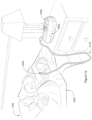
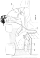
- the apparatus or device may comprise a pressure generator or blower for supplying a flow of air, to the patient 1000 via an air circuit leading to a patient interface 3000.
- the present technology comprises a method for treating a respiratory disorder comprising the step of applying positive pressure to the entrance of the airways of a patient 1000.
- the present technology comprises a method of treating Obstructive Sleep Apnea in a patient by applying nasal continuous positive airway pressure to the patient.
- a non-invasive patient interface 3000 in accordance with one aspect of the present technology comprises the following functional aspects: a seal-forming structure 3100, a plenum chamber 3200, a positioning and stabilising structure 3300 and a connection port 3600 for connection to air circuit 4170.
- a functional aspect may be provided by one or more physical components.
- one physical component may provide one or more functional aspects.
- the seal-forming structure 3100 is arranged to surround an entrance to the airways of the patient so as to facilitate the supply of air at positive pressure to the airways.
- An RPT device 4000 in accordance with one aspect of the present technology is shown in Fig. 4a , and comprises mechanical and pneumatic components 4100, electrical components 4200 and is programmed to execute one or more algorithms 4300.
- the RPT device may comprise an external housing 4010 which may be formed in two parts, an upper portion 4012 and a lower portion 4014. Furthermore, the external housing 4010 may include one or more panel(s) 4015.
- the RPT device 4000 may comprise a chassis 4016 that supports one or more internal components of the RPT device 4000. In one form a pneumatic block 4020 is supported by, or formed as part of the chassis 4016.
- the RPT device 4000 may include a handle 4018.
- FIG. 4b A schematic diagram of a pneumatic circuit of the RPT device 4000 according to an example of the present technology is shown in Fig. 4b .
- the pneumatic path of the RPT device 4000 may comprise an inlet air filter 4112, an inlet muffler 4122, a pressure generator 4140 capable of supplying air at positive pressure (preferably a blower 4142), a pneumatic block 4020 and an outlet muffler 4124.
- One or more transducers 4270, such as pressure sensors 4272 and flow sensors 4274 may be included in the pneumatic path.
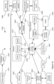
- the RPT device 4000 may include an electrical power supply 4210, one or more input devices 4220, a central controller 4230, a therapy device controller 4240, a pressure generator 4140, one or more protection circuits 4250, memory 4260, transducers 4270, data communication interface 4280 and one or more output devices 4290. Electrical components 4200 may be mounted on a single Printed Circuit Board Assembly (PCBA) 4202. In an alternative form, the RPT device 4000 may include more than one PCBA 4202.
- PCBA Printed Circuit Board Assembly
- a RPT device in accordance with one form of the present technology may include one or more air filters 4110.
- a signal from a transducer 4270 may be filtered, such as by low-pass, high-pass or band-pass filtering.
- a flow rate transducer 4274 in accordance with the present technology may be based on a differential pressure transducer, for example, an SDP600 Series differential pressure transducer from SENSIRION.
- a signal representing a flow rate such as a total flow Qt from the flow transducer 4274 is received by the central controller 4230.
- a pressure transducer 4272 in accordance with the present technology is located in fluid communication with the pneumatic path.
- An example of a suitable pressure transducer is a sensor from the HONEYWELL ASDX series.
- An alternative suitable pressure transducer is a sensor from the NPA Series from GENERAL ELECTRIC.
- a motor speed transducer 4276 is used to determine a rotational velocity of the motor 4144 and/or the blower 4142.
- a motor speed signal from the motor speed transducer 4276 is preferably provided to the therapy device controller 4240.
- the motor speed transducer 4276 may, for example, be a speed sensor, such as a Hall effect sensor.
- an anti-spillback valve is located between the humidifier 5000 and the pneumatic block 4020.
- the anti-spill back valve is constructed and arranged to reduce the risk that water will flow upstream from the humidifier 5000, for example to the motor 4144.
- An air circuit 4170 in accordance with an aspect of the present technology is a conduit or a tube constructed and arranged in use to allow a flow of air to travel between two components such as the pneumatic block 4020 and the patient interface 3000.
- the air circuit 4170 may be in fluid connection with the outlet of the pneumatic block and the patient interface.
- the air circuit may be referred to as an air delivery tube.
- supplemental oxygen 4180 is delivered to one or more points in the pneumatic path, such as upstream of the pneumatic block 4020, to the air circuit 4170 and/or to the patient interface 3000.
- a power supply (or PSU) 4210 may be located internal or external of the external housing 4010 of the RPT device 4000.
- power supply 4210 provides electrical power to the RPT device 4000 only. In another form of the present technology, power supply 4210 provides electrical power to both RPT device 4000 and humidifier 5000.
- the central controller 4230 is one or a plurality of processors suitable to control a RPT device 4000.
- a therapy engine module 4320 receives as inputs one or more of a pressure, Pm, in a patient interface 3000, and a respiratory flow of air to a patient, Qr, and provides as an output, one or more therapy parameters.
- a therapy parameter is a CPAP treatment pressure Pt.
- a therapy parameter is one or more of a level of pressure support and a target ventilation.
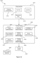
- the therapy engine module 4320 comprises one or more of the following algorithms: phase determination algorithm 4321, waveform determination algorithm 4322, ventilation determination algorithm 4323, flow limitation determination algorithm 4324, Apnea/hypopnea determination algorithm 4325. Snore determination algorithm 4326, Patency determination algorithm 4327 and Therapy parameter determination algorithm 4328.
- the RPT device 4000 does not determine phase.
- the RPT device 400 does determine phase using a phase determination algorithm 4321.
- the phase determination algorithm 4321 receives as an input a signal indicative of respiratory flow, Qr, and provides as an output a phase of a breathing cycle of a patient 1000.
- the phase output may include a discrete variable with values of one or more of inhalation, mid-inspiratory pause, and exhalation.
- the phase output may be determined to have a discrete value of inhalation when a respiratory flow Qr has a positive value that exceeds a positive threshold and the phase may be determined to have a discrete value of exhalation when a respiratory flow Qr has a negative value that is more negative than a negative threshold.
- the phase output may include a continuous variable, for example varying from 0 to 1, or 0 to 2Pi.
- a control module 4330 controls a pressure generator 4140 to provide an approximately constant positive airway pressure throughout a respiratory cycle of a patient.
- a control module 4330 controls a pressure generator 4140 to provide positive airway pressure according to a predetermined waveform of pressure vs phase.
- the waveform is maintained at an approximately constant level for all values of phase.
- the waveform is a square wave, having a higher value for some values of phase, and a lower level for other values of phase.
- a waveform determination algorithm 4322 receives as an input a value indicative of current patient ventilation, Vent, and provides as an output a waveform of pressure vs. phase.
- a ventilation determination algorithm 4323 may receive as an input a respiratory flow Qr, and determine a measure indicative of patient ventilation, Vent.
- the current value of patient ventilation, Vent may be determined as half the low-pass filtered absolute value of respiratory flow, Qr.
- a ventilation determination algorithm 4323 receives an input a respiratory flow Qr, and determines a measure indicative of patient ventilation, Vent.
- ventilation determination algorithm 4323 determines a current value of patient ventilation, Vent, as half the low-pass filtered absolute value of respiratory flow, Qr.
- the central controller executes one or more algorithms 4324 for the detection of inspiratory flow limitation.
- the algorithm 4324 receives as an input a respiratory flow signal Qr and provides as an output a metric of the extent to which the inspiratory portion of the breath exhibits inspiratory flow limitation.
- the inspiratory portion of each breath is identified by a zero-crossing detector.
- a number of evenly spaced points (for example, sixty-five), representing points in time, are interpolated by an interpolator along the inspiratory flow-time curve for each breath.
- the curve described by the points is then scaled by a scaler to have unity length (duration/period) and unity area to remove the effects of changing respiratory rate and depth.
- the scaled breaths are then compared in a comparator with a pre-stored template representing a normal unobstructed breath, similar to the inspiratory portion of the breath shown in Fig. 6a .
- a moving average of the first such scaled point is calculated by the central controller 4230 for the preceding several inspiratory events. This is repeated over the same inspiratory events for the second such point, and so on.
- sixty five scaled data points are generated by the central controller 4230, and represent a moving average of the preceding several inspiratory events, e.g. three events.
- the moving average of continuously updated values of the (e.g. sixty five) points are hereinafter called the "scaled flow", designated as Qs(t).
- a single inspiratory event can be utilised rather than a moving average.
- Shape factor 2 is calculated as the RMS deviation from unit scaled flow, taken over the middle (e.g. thirty two) points. An RMS deviation of about 0.2 units is taken to be normal. An RMS deviation of zero is taken to be a totally flow-limited breath. The closer the RMS deviation to zero, the breath will be taken to be more flow limited.
- the central controller 4230 executes one or more algorithms 4325 for the determination of the presence of apneas and/or hypopneas.
- the one or more algorithms 4325 receive as an input a respiratory flow signal Qr and provide as an output a flag that indicates that an apnea or a hypopnea has been detected.
- an apnea will be said to have been detected when a function of respiratory flow Qr falls below a flow threshold for a predetermined period of time.
- the function may determine a peak flow, a relatively short-term mean flow, or a flow intermediate of relatively short-term mean and peak flow, for example an RMS flow,
- the flow threshold may be a relatively long-term measure of flow.
- the therapy parameter determination algorithm 4328 determines the treatment pressure Pt as a function of indices or measures of one or more of flow limitation, apnea, hypopnea, patency, and snore. In one implementation, these measures are determined on a single breath basis, rather than on an aggregation of several previous breaths.
- Fig. 4e is a flow chart illustrating a method 4500 carried out by the central controller 4230 as one implementation of the algorithm 4328.
- the method 4500 starts at step 4520, at which the central controller 4230 compares the measure of the presence of apnea / hypopnea with a first threshold, and determines whether the measure of the presence of apnea / hypopnea has exceeded the first threshold for a predetermined period of time, indicating an apnea / hypopnea is occurring. If so, the method 4500 proceeds to step 4540; otherwise, the method 4500 proceeds to step 4530.
- the central controller 4230 compares the measure of airway patency with a second threshold.
- the detected apnea / hypopnea is deemed central, and the method 4500 proceeds to step 4560; otherwise, the apnea / hypopnea is deemed obstructive, and the method 4500 proceeds to step 4550.
- the central controller 4230 compares the measure of flow limitation with a third threshold. If the measure of flow limitation exceeds the third threshold, indicating inspiratory flow is limited, the method 4500 proceeds to step 4550; otherwise, the method 4500 proceeds to step 4560.
- the central controller 4230 increases the treatment pressure Pt by a predetermined pressure increment ⁇ P , provided the increased treatment pressure Pt would not exceed an upper limit Pmax.
- the predetermined pressure increment ⁇ P and upper limit Pmax are 1 cmH20 and 20 cmH20 respectively. The method 4500 then returns to step 4520.
- the central controller 4230 decreases the treatment pressure Pt by a decrement, provided the decreased treatment pressure Pt would not fall below a lower limit Pmin.
- the method 4500 then returns to step 4520.
- the decrement is proportional to the value of Pt-Pmin, so that the decrease in Pt to the lower limit Pmin in the absence of any detected events is exponential.
- the decrement in Pt could be predetermined, so the decrease in Pt to the lower limit Pmin in the absence of any detected events is linear.
- a control module 4330 in accordance with one aspect of the present technology receives as an input a target treatment pressure Pt, and controls a pressure generator 4140 to deliver that pressure.
- a control module 4330 in accordance with one aspect of the present technology receives as an input an EPAP pressure and an IPAP pressure, and controls a pressure generator 4140 to deliver those respective pressures.
- the central controller 4230 executes one or more methods for the detection of fault conditions.
- the fault conditions detected by the one or more methods includes at least one of the following:
- a humidifier 5000 to change the absolute humidity of air for delivery to a patient relative to ambient air.
- the humidifier 5000 is used to increase the absolute humidity and increase the temperature of the flow of air relative to ambient air before delivery to the patient's airways.
- Some known performance requirements and/or design requirements in relation to humidifier design may include: reduction of a volume and/or a footprint of the humidifier (e.g. for bedside placement), ability to provide humidification for an entire therapy session, efficient use of the water supply, requirement to couple to the respiratory apparatus, minimisation of pressure drop for the flow of air through the humidifier, and/or requirement to maintain a positive pressure at the entrance of the patient's airways (e.g. therefore a requirement to maintain a positive pressure in the humidifier). It is one of the aims of the present technology to address, or improve, at least some of the above performance requirements and/or design requirements.
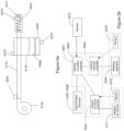
- a humidifier 5000 may comprise a humidifier reservoir 5110, a heating element 5240 and one or more sensors 5270.
- the humidifier 5000 may be configured to receive a flow of air from a pressure generator 4140 via an air circuit 4170, and deliver a flow of humidified air to a patient interface 3000 (not shown in Fig. 5a ), for example via a heated air circuit 4171.
- the humidifier 5000 may comprise one or more controllers 5250 such as a heated air circuit controller 5254, a heating element controller 5252 or a central humidifier controller 5251, which may be discrete controllers or one controller performing multiple functions.
- the controller(s) 5250 may be in electrical communication with one or more of: one or more sensors 5270, input devices 4220, output devices 4290, heated air circuit 4171 and a heating element 5240 as shown in Fig. 5b .
- a humidifier 5000 may comprise a water reservoir dock 5130 to receive a water reservoir 5110.
- the water reservoir dock 5130 may comprise a cavity 5160 formed therein to receive the water reservoir 5110.
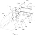
- the water reservoir dock 5130 may be integrated with the humidifier 5000 as shown in Figs. 13 to 16 .
- the water reservoir dock 5130 may also connect the water reservoir 5110 to the pneumatic path.
- the reservoir dock 5130 comprises a dock air outlet 5168 to deliver a flow of air to a water reservoir 5110, a dock air inlet 5170 to receive the flow of air that has been humidified in the water reservoir 5110, and a humidifier outlet 5172 to transfer the flow of humidified air to the air circuit 4170.
- the cavity 5160 may include a top portion configured to cover at least a portion of the lid of the reservoir 5110 and a bottom portion including the heater plate 5120.
- reservoir dock 5130 may be provided separately to a humidifier 5000 in an alternate arrangement. In such an arrangement, additional interfaces may be used to connect the reservoir dock 5130 to the humidifier 5000.
- a water reservoir dock 5130 may comprise an opening in a substantially horizontal plane, so that the water reservoir 5110 may be inserted from above or below the water reservoir dock 5130.
- the water reservoir 5110 is configured to add humidity to a flow of air from the RPT device 4000.
- the water reservoir 5110 may be configured to do so by encouraging the flow of air to travel in a tortuous path through the reservoir 5110.
- the reservoir 5110 is also configured to discourage egress of liquid therefrom, such as when the reservoir 5110 is displaced and/or rotated from its normal, working orientation, liquid will not leak through any apertures and/or in between its sub-components.
- the reservoir 5110 may also be configured to prevent losses in pneumatic pressure through leak and/or flow impedance.
- the water reservoir 5110 comprises an inlet 5118 for receiving the flow of air into the reservoir 5110, and an outlet 5122 for delivering a flow of air from the reservoir 5110.
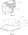
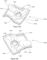
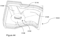
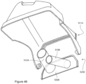
- the reservoir 5110 includes an inlet tube 5124 and an outlet tube 5126 (e.g., see Figs. 10 and 12 ).
- the inlet 5118 and inlet tube 5124 are integrally formed as one inlet component and the outlet 5122 and the outlet tube 5126 are integrally formed as one outlet component (see Figs. 10-12 , 22-29 and 47a-52b ).
- the inlet tube 5124 and/or the outlet tube 5126 may be separate tubes that are coupled to the inlet 5118 and/or the outlet 5122 respectively (see Figs. 41a to 46 ).
- the water reservoir 5110 is configured to increase the humidity of the flow of air as it flows through the reservoir 5110.
- the compliant portion 5116 may be provided as part of the reservoir lid 5114 or as part of the reservoir base 5112, or independently of both, for example as part of an intermediate portion 5202.
- the compliant portion 5116 may be engaged with the reservoir lid 5114 or the reservoir base 5112 by any number of means including, and not limited to, ultrasonic welding, friction fitting, gluing or by using an intermediate component.
- the intermediate portion 5202 may include the compliant portion 5116 and a carrier 5117 (as shown in Fig. 12 ).
- the compliant portion 5116 preferably includes a sufficiently resilient construction so as to be able to resist forces and/or pressures generated in the reservoir 5110, such as those generated by the user, the reservoir dock 5130 and/or the flow of air flowing through the reservoir 5110.
- the compliant portion 5116 is also preferably compliant to be able couple to the lid 5114 and/or the base 5112, and conform to its shape.
- the carrier 5117 of the intermediate portion may be constructed from a nylon material of approximately 2 mm thickness (such as 1 mm, 1.5 mm, 2.5 mm or 3 mm), and a silicone material may be used to overmould onto the carrier 5117 to form the compliant portion of the intermediate portion 5202.
- the compliant portion 5116 may couple to the lid 5114 and/or the base 5112, and the base 5112 and/or the lid 5114 may be formed as two separate parts that are able to be assembled with the compliant portion 5116 coupled therebetween.
- Fig. 21 illustrates this effect by indicating the distributed forces or pressures that are applied to the lid 5114 and the base 5112 by the arrows shown.
- Fig. 21 shows forces and pressures in the vertical direction only, as in this form the thermal engagement occurs in the vertical direction.
- the presence of above-atmospheric pressure within the water reservoir 5110 results in forces in the direction of thermal engagement, and is reacted by the water reservoir dock 5130 at its contacting surfaces, thereby pushing the base 5112 of the water reservoir 5110 and the heater plate 5120 together in the direction of thermal engagement.
- the magnitude of this force may be between about 5 N and about 15 N when measured at the heater plate 5120 at 20 cm H 2 O of pressure.
- substantially the same effects as those described above may be achieved with a non-opening compliant portion of a water reservoir 5110.
- the water reservoir 5110 and the reservoir dock 5130 may be arranged so that elasticity or flexibility is provided by an elastomeric material or a joint that allows freedom of movement (e.g. a sliding connection, or a concertina section of pliable plastic or a flexible portion in the water reservoir) in the direction of the heat transfer.
- the lid 5114 and the base 5112 may be unconstrained relative to each other in the direction of thermal contact.
- the reservoir 5110 may then be constrained in the direction of the heat transfer in another manner (e.g.
- a water reservoir dock or a similar housing
- a water reservoir dock or a similar housing
- another opening to re-fill the water reservoir 5110 may be introduced on the reservoir 5110, such as on the lid 5114, and it may comprise a separate seal around such opening.
- Fig. 34 shows an example of such an arrangement, including a base 5174, a top 5176, a compliant portion 5178 and a re-filling cap 5180.
- the base, the top and the compliant portion may be affixed together in another arrangement, wherein re-filling of the reservoir would be accommodated by the re-filling cap 5180.
- the re-filling cap 5180 may be placed such that, when the humidifier reservoir 5110 is engaged with the reservoir dock 5130, the re-filling cap 5180 is not accessible.
- the compliant portion 5178 may be replaced by any mechanism known in the art that is able to accommodate a change in vertical length within a reservoir.
- the flow of air may be used to improve the level of thermal contact between the humidifier reservoir 5110 and the heater plate 5120 by pressurisation or inflation of a secondary component.
- the secondary component may be a chamber, body or surface that acts on the humidifier reservoir 5110, which in turn pushes the water reservoir 5110 and the heater plate 5120 together in the direction of thermal engagement.
- the secondary component may act upon the heater plate 5120 to push the heater plate 5120 and water reservoir 5110 together in the direction of thermal engagement.
- the secondary component may be arranged externally to the reservoir 5110 and/or the heater plate 5120. Furthermore, the secondary component may be configured to vary the area in contact with the reservoir 5110 and/or the heater plate 5120, to further profile the change to thermal contact as pressure of the flow of air changes.
- the reservoir 5110 achieves spillback protection by arranging the inlet tube inner end 5125 so that when the reservoir 5110 is rotated by 90 degrees in any direction from its working, horizontal orientation the given maximum volume of water is able to be stored in the reservoir 5110 without reaching the inlet tube inner end 5125.
- the lid portion 5114, the intermediate portion 5202 and the base portion 5112 may be configured in any number of ways.
- the relative sizes of the lid portion 5114 and the base portion 5112 may vary, and the lid portion 5114 and/or the base portion 5112 may further comprise multiple materials or components in its construction.
- One or more of the inlet tube 5124 and the outlet tube 5126 may be removably or releasably coupled to the lid portion 5114 or the base portion 5112, for example as a part of the intermediate portion.
- the intermediate portion may also be configured to initially engage the lid portion 5114 and/or the base portion 5112, for example by being configured to be inserted into the lid portion 5114 or the base portion 5112.
- FIG. 45a and 45b An exemplary cross-section of the assembled lid 5114 is shown in Figs. 45a and 45b .
- the diameter of the inlet tube 5124 or the locating portion 5196 may be varied along its length, for example in a frustro-conical arrangement, so as to progressively engage with each other.
- the inlet tube 5124, and the locating portion 5196 may also incorporate a complementary retaining mechanism such as a protrusion/slot combination 5205 as shown in Figs. 45a and 45b .
- overfilling of the water reservoir 5110 may reduce effectiveness of a spill prevention feature. For example, if the reservoir 5110 was to be rotated away from its intended orientation while overfilled, the overfilled liquid in the reservoir 5110 may reach the inlet 5118 at a lower angle of tilt than if the reservoir 5110 had been only filled with the predetermined, maximum volume of liquid.
- some prior art humidifier water reservoirs have included a water filling indication mark to reduce occurrence of such overfilling, however this may only go some way towards ameliorating this risk as the user (e.g. patient 1000) may not be able to see, or be aware of the meaning of, the indication mark for example.
- Some prior art humidifier water reservoirs comprise one or more tubes, which can act as egress paths for liquid (typically water) when the reservoir is filled with a volume of liquid which exceeds a threshold volume.
- liquid typically water
- One example of such prior art humidifier is described in PCT publication WO 2009/156921 .
- one disadvantage of such an arrangement may be that if the reservoir is filled to this threshold volume, any movement of the reservoir may lead to egress of liquid from the reservoir (e.g. from movement of the volume of liquid). Consequently, transport of such a reservoir (e.g. from the patient's kitchen or bathroom) without spillage may be difficult, and the risk of spillage during usage (i.e. through the one or more tubes of the reservoir) may be high.
- such prior art humidifier water reservoirs often comprise a water filling indication mark indicating the recommended predetermined maximum volume of water that the reservoir is to be filled with, where the recommended predetermined maximum volume of water is below (sometimes significantly below) the threshold volume at which water may begin to spill out of the one or more tubes in the reservoir.
- such prior art humidifier water reservoirs may further comprise a secondary chamber configured to contain the water which has escaped the reservoir, for example before the water may enter the RPT device located upstream.
- Another aspect of this technology is the inclusion of one or more overfill protection features configured to prevent filling the reservoir above the maximum volume of water when filling the humidifier reservoir, such as in its open configuration and/or the closed configuration.
- the at least one orifice defines egress path(s) of water when the predetermined maximum volume of water is exceeded.
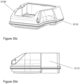
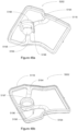
- Fig. 30a shows the water reservoir 5110 in its open configuration, wherein an upper flange or lip 5224 of the base 5112 does not span the perimeter of the entire opening, creating an orifice 5138.
- Fig. 30b shows a portion of the base 5112 indicating the at least one orifice 5138.
- the at least one orifice 5138 may be in the form of one or more apertures, holes, slits or slots, or any other form that allows communication of fluid into and out of the water reservoir 5110.
- the at least one orifice 5138 may be formed in one or more positions around the upper flange or lip 5224 of the base 5112.
- the overfill protection feature may include a sloped profile 5139.
- the reservoir base 5112 may be arranged so that its side profile has a sloped profile 5139 in one or more directions. This arrangement may also indicate over-filling when the reservoir base 5112 is filled with water.
- the sloped profile defines an egress path of water when the predetermined maximum volume of water is exceeded.
- the overfill protection feature is independent of the inlet tube 5124 and the outlet tube 5126. That is, the egress path of water is provided by the at least one orifice 5138 or the sloped profile 5139 rather than spilling out via the inlet tube 5124 and/or the outlet tube 5126.
- a threshold volume of water which is required for the water to reach the inlet tube 5124 and/or the outlet tube 5126, and thus for the tubes 5124, 5126 to define an egress path of water may be larger than the predetermined maximum volume of water.
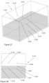
- the reservoir 5110 may comprise at least one water filling indication mark 5140 (e.g. on the base 5112 as shown in Figs. 57a and 57b ).
- the water filling indication mark 5140 may indicate to the user the predetermined maximum volume of water for the reservoir 5110 to contain, such as by indicating a water level which the reservoir 5110 is to be filled to.
- Further water filling indication marks 5140_a, 5140_b (e.g., as shown in Fig. 57a and 57b ) may indicate the level of fill of the reservoir 5110. In one arrangement (as shown in Figs.
- the reservoir 5110 may be further configured so that the predetermined maximum volume of water is substantially identical to a maximum volume of water which will remain in the reservoir without causing egress via the at least one orifice 5138 as shown (or the sloped profile 5139 - not shown).
- the user e.g. patient 1000
- the user would cause water egress via the at least one orifice 5138 or the sloped profile 5139.
- the reservoir 5110 may be further configured, for example as shown in Figs. 58a and 58b , so that when the reservoir 5110 is in its closed configuration, a threshold volume of water required for the water (indicated by water line 5141_2) to reach the inlet tube 5124 and/or the outlet tube 5126 may be a greater volume than the predetermined maximum volume of water (indicated by water line 5141_1).
- the water line at the predetermined maximum volume of water 5141_1 may be substantially in line with a base or lower edge of the at least one orifice 5138 to allow egress of any excess water that is added above the water filling indication mark 5140.
- Such an arrangement may allow the patient 1000 to more easily transport the reservoir 5110 while it contains the predetermined maximum volume of water, as well as reduce a risk of water spillage/egress while the humidifier 5000 is in use.
- the base or lower edge of the at least one orifice 5138 or sloped profile 5139 may be above the predetermined maximum volume of water (indicated by water line 5141_1) but below the threshold volume of water (indicated by water line 5141_2).
- the base or lower edge of the at least one orifice 5138 or sloped profile 5139 may be closer to the predetermined maximum volume of water (indicated by water line 5141_1) than the threshold volume of water (indicated by water line 5141_2).
- a compliant portion 5116 sealingly engages the base 5112 and the reservoir lid 5114 and blocks or seals the orifice 5138 or sloped profile 5139 preventing fluid communication into and out of the water reservoir 5110.
- Fig. 31a shows that when the reservoir lid 5114 is closed (lid not shown in this image), the compliant portion 5116 sealingly engages with the base 5112 on the outside of the orifice 5138 and no longer allows communication of liquid or air into and out of the water reservoir 5110 through the orifice 5138.
- the compliant portion 5116 would engage with the base 5112 to surround the edges of the sloped profile preventing communication of liquid or air into and out of the water reservoir 5110 through the sloped profile 5139 as shown in Fig. 31b .
- an overfill prevention feature may be configured to prevent overfilling when a user is attempting to fill the reservoir 5110 while in its closed configuration, for example via the inlet 5118 or outlet 5122.
- the overfill prevention feature may form one or more air locks to prevent further ingress of liquid into the reservoir 5110 when the predetermined maximum volume of liquid is in the reservoir 5110.
- one or more air locks when filling the reservoir 5110 in its closed configuration via the inlet 5118 or outlet 5122, one or more air locks would form an enclosure of air in the reservoir 5110 that is not displaced by the volume of liquid in the reservoir 5110.
- the reservoir 5110 is in an orientation such that the normal to the inlet 5118 and the outlet 5122 are oriented vertically, as a user would orient the reservoir 5110 while filling it with water.
- the water level 5184 would rise, and reach the level shown on Fig.
- the reservoir 5110 would thus not be able to receive any further volume of water into its interior volume. Adding further water would fill the inlet tube 5124 or the outlet tube 5126 depending upon whether the reservoir was being refilled through the inlet 5118 or the outlet 5122 respectively and then overflow out of the inlet 5118 or outlet 5122 respectively. This would indicate to the user that the reservoir 5110 was being overfilled.
- the volume of water in the reservoir 5110 when any further ingress of water into the reservoir 5110 is prevented by formation of the one or more air locks is substantially equal to the predetermined maximum volume of liquid to be retained in the reservoir 5110.
- the reservoir 5110 may allow further filling of the inlet tube 5124 and/or the outlet tube 5126 although further ingress of water into the interior volume is prevented by the air locks.
- the volume of liquid in the reservoir 5110 when the air locks are formed, as well as the volume of the inlet tube 5124 and/or the outlet tube 5126 may be configured so that when added together, they are substantially equal to the predetermined maximum volume of liquid to be retained in the reservoir 5110.
- a user may fill the reservoir 5110 in one of a multiple orientations while closed.
- the reservoir 5110 may be configured such that the appropriate air locks are formable at one of, or a plurality of the multiple orientations.
- the air locks need not be formed solely by occlusion of the inlet tube 5124 and/or the outlet tube 5126.
- one or more air locks may be formed by occlusion of any cavities or ports which may allow fluid communication between the interior and the exterior of the reservoir 5110.
- the occlusion need not be performed by the volume of liquid in the reservoir 5110.
- the volume of liquid as it is increased, may deform or move another component to form a seal (and thus an air lock) in the reservoir.
- the lid protrusion 5142 may be further configured with a taper as shown in Fig. 33 .
- the taper may be directed to increase in height away from the direction of insertion, to increase the amount of interference between the protrusion 5142 and the dock 5130 progressively during insertion.
- the lid protrusion 5142 may be a recess, and the dock locking recess 5144 may be a corresponding protrusion.
- one of any number of retaining features that are known in the art may be used to achieve the same outcomes as described above.
- the humidifier 5000 may comprise a humidity sensor to detect a relative humidity of the ambient air.
- the humidity sensor may be an absolute humidity sensor or a relative humidity sensor.
- a value of absolute humidity may be determined based on measured values of relative humidity and temperature of the flow of the air.
- the heating element 5240 may be a heat generating component such as an electrically resistive heating track.
- a heating element 5240 is a layered heating element such as one described in the PCT Patent Application Publication Number WO 2012/171072 .
- a heated air circuit 4171 may be used in addition to, or instead of, the air circuit 4170. Temperature of the flow of air that is output from the humidifier 5000 may be higher than ambient temperature. As a result, heat loss may occur from the flow of air to the ambient air, thereby increasing the relative humidity of the humidified flow of air. In some cases, condensation may occur where the relative humidity increases to at or near 100% RH.
- a humidifier 5000 may comprise a humidifier controller 5250 as shown in Fig. 5b .
- the humidifier controller 5250 may be a part of the central controller 4230.
- the humidifier controller 5250 may be a separate controller, which may be in communication with the central controller 4230.
- the humidifier controller 5250 may receive as inputs (e.g. from sensors 5270) measures of characteristics (such as temperature, humidity, pressure and/or flow rate), for example of the flow of air, the water in the reservoir 5110 and/or the humidifier 5000.
- the humidifier controller 5250 may also be configured to execute or implement humidifier algorithms and/or deliver one or more output signals.
- the humidifier controller may comprise a plurality of controllers, such as a central humidifier controller 5251, a heated air circuit controller 5254 configured to control the temperature of a heated air circuit 4171 and/or a heating element controller 5252 configured to control the temperature of a hot plate.
- the heated air circuit controller 5254 may receive an input from one or more sensors to control operation of the heated air circuit 4171.
- the heated air circuit controller 5254 may receive from sensors 5270 the temperature and the relative humidity of the humidified flow of air to adjust the heat output by the heated air circuit 4171.
- Air will be taken to include breathable gases, for example atmospheric air with supplemental oxygen.
- CPAP treatment will be taken to mean the application of a supply of air to the entrance to the airways at a pressure that is continuously positive with respect to atmosphere.
- Polycarbonate a typically transparent thermoplastic polymer of Bisphenol-A Carbonate.
- any and all components herein described are understood to be capable of being manufactured and, as such, may be manufactured together or separately.
- Example 5 The apparatus as described in any one of examples 1-4, wherein the chamber is part of the reservoir.
- Example 6 The apparatus as described in any one of examples 1-5, wherein the chamber further comprises a compliant portion.
- Example 7 The apparatus as described in any one of examples 1-6, wherein the apparatus further comprises a dock configured to receive the reservoir, and the dock comprises the heater plate.
- Example 8 The apparatus as described in example 7, wherein the dock further comprises a cavity having a top portion and a bottom portion, the bottom portion having the heater plate located thereon, the cavity configured to retain at least a portion of the reservoir therein.
- Example 9 The apparatus as described in example 8, wherein the compliant portion is compressed to enable insertion of the reservoir into the cavity of the dock.
- Example 10 The apparatus as described in any one of examples 8 or 9, wherein the top portion of the cavity is moveable between an open and closed configuration to facilitate insertion of the reservoir into the cavity.
- Example 11 The apparatus as described in any one of examples 6-10, wherein the compliant portion is configured to adjust in size as the first pressure is varied to vary the level of thermal engagement between the heater plate and the conductive portion.
- Example 12 The apparatus according to any one of examples 1-11, wherein the reservoir further includes a base and a lid, the base structured to hold a volume of liquid and including the conductive portion.
- Example 13 The apparatus according to example 12, wherein the base and lid are pivotably coupled together.
- Example 14 The apparatus according to any one of examples 12-13, wherein the compliant portion forms a seal between the base and lid.
- Example 15 The apparatus according to any one of examples 12-14, wherein the reservoir further includes a latch to secure the base and lid together.
- Example 16 The apparatus according to any one of examples 7-15, wherein the reservoir further comprises at least one handle to facilitate coupling of the reservoir to the dock.
- Example 17 The apparatus according to any one of examples 8-16 wherein the reservoir further includes a retaining clip adapted to engage with a recess on the dock to retain the reservoir in the cavity of the dock.
- Example 18 The apparatus according to any one of examples 7 to 17. wherein the reservoir is structured to prevent refilling of the reservoir when the reservoir is coupled to the dock.
- Example 22 The apparatus according to example 21, wherein the overfill protection element comprises at least one orifice formed in a wall of the reservoir, the at least one orifice defines an egress path of water when the predetermined maximum volume of water is exceeded.
- Example 23 The apparatus according to example 21, wherein the overfill protection element comprises a sloped profile in the side profile of a wall of the reservoir, the sloped profile defines an egress path of water when the predetermined maximum volume of water is exceeded.
- Example 24 A method for varying thermal contact between a heater plate and a reservoir in a humidification system for humidifying a flow of air, the method comprising: varying a pressure of the flow of air in the reservoir that is in fluid communication with the flow of air to vary a force between the heater plate and the reservoir.
- Example 25 An apparatus for humidifying a flow of air, comprising:
- Example 26 The apparatus as described in example 25, further comprising a dock connectable with the reservoir.
- Example 27 The apparatus as described in example 26, wherein the dock is configured to constrain the reservoir from opening in the direction of thermal contact.
- Example 28 A reservoir configured to contain a volume of liquid for humidifying a pressurised flow of air, comprising:
- Example 29 The reservoir as described in example 28, wherein the compliant portion comprises an outlet tube, and a baffle, the baffle being configured to connect to the inlet tube.
- Example 31 The apparatus as described in example 30, wherein the apparatus is configured so that the thermal engagement is in a first direction that is substantially normal to a surface of the conductive portion.
- Example 32 A method of varying a level of thermal engagement in a humidifier apparatus, the method comprising:
- Example 33 A water reservoir for a humidifier apparatus, the reservoir comprising:
- Example 34 A water reservoir for a humidifier apparatus, the reservoir comprising:
- Example 35 The water reservoir as described in example 34, wherein the at least two configurations comprises an open configuration and a closed configuration.
- Example 36 The water reservoir as described in example 35, wherein the at least one or the inlet tube or the outlet tube is collapsible to form the closed configuration.
Landscapes
- Health & Medical Sciences (AREA)
- Life Sciences & Earth Sciences (AREA)
- Veterinary Medicine (AREA)
- Biomedical Technology (AREA)
- Heart & Thoracic Surgery (AREA)
- Pulmonology (AREA)
- Animal Behavior & Ethology (AREA)
- General Health & Medical Sciences (AREA)
- Public Health (AREA)
- Engineering & Computer Science (AREA)
- Emergency Medicine (AREA)
- Anesthesiology (AREA)
- Hematology (AREA)
- Physics & Mathematics (AREA)
- Biophysics (AREA)
- Pathology (AREA)
- Medical Informatics (AREA)
- Molecular Biology (AREA)
- Surgery (AREA)
- Physiology (AREA)
- Air Humidification (AREA)
- Percussion Or Vibration Massage (AREA)
- Accommodation For Nursing Or Treatment Tables (AREA)
- Respiratory Apparatuses And Protective Means (AREA)
Claims (15)
- Reservoir (5110), das konfiguriert ist, ein vorbestimmtes maximales Wasservolumen zu enthalten, das aufweist:eine Basis (5112);einen Deckel (5114), der strukturiert ist, mit der Basis verbunden zu werden, um es zu ermöglichen, dass das Reservoir zwischen einer offenen und einer geschlossenen Konfiguration umwandelbar ist;ein Einlassrohr (5124), das konfiguriert ist, einen Luftstrom in den Hohlraum abzugeben, wobei das Einlassrohr ein inneres Einlassrohrende (5125) und ein äußeres Einlassrohrende aufweist; undein Auslassrohr (5126), das konfiguriert ist, einen befeuchteten Luftstrom aus dem Hohlraum abzugeben, wobei das Auslassrohr ein inneres Auslassrohrende (5127) und ein äußeres Auslassrohrende aufweist,wobei das Reservoir einen Hohlraum aufweist, der konfiguriert ist, das vorbestimmte maximale Wasservolumen zu enthalten;wobei das innere Einlassrohrende und das innere Auslassrohrende innerhalb des Hohlraums angeordnet sind und das äußere Einlassrohrende und das äußere Auslassrohrende in einer Wand des Reservoirs angeordnet sind;dadurch gekennzeichnet, dassdas Einlassrohr unter dem Auslassrohr verläuft oder das Auslassrohr unter dem Einlassrohr verläuft.
- Reservoir (5110) nach Anspruch 1,wobei eine erste Achse durch das innere Einlassrohrende (5125) und das äußere Auslassrohrende definiert ist;wobei eine zweite Achse durch das innere Auslassrohrende (5127) und das äußere Auslassrohrende definiert ist;undwobei sich vorzugsweise die erste Achse und die zweite Achse von oben und/oder von der Seite gesehen schneiden.
- Reservoir (5110) nach Anspruch 2, wobei, wenn das Reservoir um etwa 90° zur normalen Arbeitsausrichtung geneigt ist, sich die erste Achse auf einem ersten Winkel befindet, so dass das innere Einlassrohrende (5125) und das äußere Einlassrohrende auf unterschiedlichen Höhen angeordnet sind, so dass ein Pegel des vorbestimmten maximalen Wasservolumens unter mindestens einem von dem inneren Einlassrohrende oder dem äußeren Einlassrohrende liegt, um ein Zurücklaufen von Wasser durch das Einlassrohr zu verhindern.
- Reservoir (5110) nach Anspruch 3, wobei das Reservoir ferner so konfiguriert ist, dass, wenn das Reservoir um etwa 90° zur normalen Arbeitsausrichtung geneigt ist, sich die zweite Achse auf einem zweiten Winkel befindet, so dass das innere Auslassrohrende (5127) und das äußere Auslassrohrende auf unterschiedlichen Höhen angeordnet sind, so dass der Pegel des vorbestimmten maximalen Wasservolumens unter mindestens einem des inneren Auslassrohrendes oder des äußeren Auslassrohrendes liegt, um ein Zurücklaufen von Wasser durch das Auslassrohr zu verhindern.
- Reservoir (5110) nach einem der vorhergehenden Ansprüche, wobei die Basis (5112) und der Deckel (5114) beweglich, vorzugsweise schwenkbar, miteinander gekoppelt sind.
- Reservoir (5110) nach einem der vorhergehenden Ansprüche, wobei der Deckel (5114) das Einlassrohr (5124) und das Auslassrohr (5126) aufweist.
- Reservoir (5110) nach einem der vorhergehenden Ansprüche, wobei das Reservoir einen nachgiebigen Abschnitt (5116) aufweist, der eine Dichtung zwischen der Basis (5112) und dem Deckel (5114) bildet.
- Reservoir (5110) nach einem der vorhergehenden Ansprüche, wobei das Reservoir mindestens eine Wasserfüllanzeigemarkierung (5140) aufweist, die dem Benutzer das vorbestimmte maximale Wasservolumen anzeigt.
- Reservoir (5110) nach einem der vorhergehenden Ansprüche, wobei der Deckel (5114) das Einlassrohr (5124) und das Auslassrohr (5126) aufweist; wobei das äußere Einlassrohrende einen Einlass (5118) des Reservoirs definiert;wobei das äußere Auslassrohrende einen Auslass (5122) des Reservoirs definiert; undwobei der Deckel einen Deflektor (5136) aufweist, der in der Nähe des inneren Einlassrohrendes (5125) angeordnet ist.
- Reservoir (5110) nach Anspruch 9, wobei der Deflektor (5136) integral als eine Verlängerung des Einlassrohrs (5124) ausgebildet ist.
- Reservoir (5110) nach einem der Ansprüche 2 bis 4, wobei die erste Achse des Einlassrohrs (5124) und die zweite Achse des Auslassrohrs (5126) sich schneiden, wenn sie aus mehreren zueinander orthogonalen Winkeln betrachtet werden.
- Reservoir (5110) nach einem der vorhergehenden Ansprüche, wobei das Einlassrohr (5124) und das Auslassrohr (5126) so konfiguriert sind, dass, wenn das Reservoir das vorbestimmte maximale Wasservolumen enthält, sich mindestens eines von dem inneren Einlassrohrende (5125) oder dem äußeren Einlassrohrende und mindestens eines von dem inneren Auslassrohrende (5127) oder dem äußeren Auslassrohrende unabhängig von der Ausrichtung des Reservoirs über dem Pegel des vorbestimmten maximalen Wasservolumens befinden.
- Therapeutische Druckbeatmungsvorrichtung (4000), die einen Druckerzeuger (4140) zum Liefern eines Luftstroms mit positivem Druck und eine Vorrichtung (5000) zum Befeuchten des Luftstroms aufweist, die in die therapeutische Druckbeatmungsvorrichtung integriert ist, wobei die Vorrichtung zum Befeuchten des Luftstroms aufweist:ein Dock (5130), das eine Heizplatte (5120) aufweist, die konfiguriert ist, thermisch mit einem leitfähigen Abschnitt (5152) der Reservoirbasis (5112) zu koppeln;das Reservoir (5110) nach einem der vorhergehenden Ansprüche, wobei das Dock konfiguriert ist, das Reservoir zumindest teilweise aufzunehmen.
- Therapeutische Druckbeatmungsvorrichtung (4000) nach Anspruch 13, wobei das Dock (5130) einen Dock-Luftauslass (5168), der konfiguriert ist, den Luftstrom an das Einlassrohr (5124) abzugeben, und einen Dock-Lufteinlass (5170) aufweist, um den Luftstrom aufzunehmen, der im Reservoir (5110) befeuchtet wurde.
- Therapeutische Druckbeatmungsvorrichtung (4000) nach Anspruch 14, die einen Befeuchterauslass (5172) aufweist, der konfiguriert ist, über eine Luftleitung (4170) mit einer Patientenschnittstelle verbunden zu werden;
wobei die therapeutische Druckbeatmungsvorrichtung so konfiguriert ist, dass das Reservoir (5110) aus dem Dock (5130) entfernt werden kann, während der Luftkreislauf am Befeuchterauslass angeschlossen bleibt.
Applications Claiming Priority (7)
| Application Number | Priority Date | Filing Date | Title |
|---|---|---|---|
| AU2013900901A AU2013900901A0 (en) | 2013-03-15 | A Humidifier Reservoir | |
| AU2013901965A AU2013901965A0 (en) | 2013-05-31 | A humidifier reservoir | |
| AU2013902601A AU2013902601A0 (en) | 2013-07-15 | A humidifier reservoir | |
| AU2013904923A AU2013904923A0 (en) | 2013-12-17 | A Humidifier Reservoir | |
| EP14763136.0A EP2968829B1 (de) | 2013-03-15 | 2014-03-14 | Wasserreservoirs und verfahren zur überfüllungsvermeidung in einem befeuchterreservoir |
| EP21169271.0A EP3881887B1 (de) | 2013-03-15 | 2014-03-14 | Beatmungsdruckbehandlungsvorrichtung |
| PCT/AU2014/000264 WO2014138804A1 (en) | 2013-03-15 | 2014-03-14 | A humidifier reservoir |
Related Parent Applications (3)
| Application Number | Title | Priority Date | Filing Date |
|---|---|---|---|
| EP14763136.0A Division EP2968829B1 (de) | 2013-03-15 | 2014-03-14 | Wasserreservoirs und verfahren zur überfüllungsvermeidung in einem befeuchterreservoir |
| EP21169271.0A Division-Into EP3881887B1 (de) | 2013-03-15 | 2014-03-14 | Beatmungsdruckbehandlungsvorrichtung |
| EP21169271.0A Division EP3881887B1 (de) | 2013-03-15 | 2014-03-14 | Beatmungsdruckbehandlungsvorrichtung |
Publications (2)
| Publication Number | Publication Date |
|---|---|
| EP4176917A1 EP4176917A1 (de) | 2023-05-10 |
| EP4176917B1 true EP4176917B1 (de) | 2025-07-09 |
Family
ID=51535616
Family Applications (8)
| Application Number | Title | Priority Date | Filing Date |
|---|---|---|---|
| EP22191738.8A Active EP4122517B1 (de) | 2013-03-15 | 2014-03-14 | Druckbeatmungsvorrichtung |
| EP22208463.4A Withdrawn EP4176916A1 (de) | 2013-03-15 | 2014-03-14 | Reservoir und therapeutische druckbeatmungsvorrichtung |
| EP21169271.0A Active EP3881887B1 (de) | 2013-03-15 | 2014-03-14 | Beatmungsdruckbehandlungsvorrichtung |
| EP22208705.8A Active EP4176917B1 (de) | 2013-03-15 | 2014-03-14 | Reservoir und therapeutische druckbeatmungsvorrichtung |
| EP14763136.0A Active EP2968829B1 (de) | 2013-03-15 | 2014-03-14 | Wasserreservoirs und verfahren zur überfüllungsvermeidung in einem befeuchterreservoir |
| EP22177432.6A Active EP4082594B1 (de) | 2013-03-15 | 2014-03-14 | Wasserbehälter und druckbeatmungsvorrichtung |
| EP22191911.1A Active EP4122518B1 (de) | 2013-03-15 | 2014-03-14 | Wasserreservoir und therapeutische druckbeatmungsvorrichtung |
| EP22177451.6A Active EP4079363B1 (de) | 2013-03-15 | 2014-03-14 | Druckbeatmungsvorrichtung |
Family Applications Before (3)
| Application Number | Title | Priority Date | Filing Date |
|---|---|---|---|
| EP22191738.8A Active EP4122517B1 (de) | 2013-03-15 | 2014-03-14 | Druckbeatmungsvorrichtung |
| EP22208463.4A Withdrawn EP4176916A1 (de) | 2013-03-15 | 2014-03-14 | Reservoir und therapeutische druckbeatmungsvorrichtung |
| EP21169271.0A Active EP3881887B1 (de) | 2013-03-15 | 2014-03-14 | Beatmungsdruckbehandlungsvorrichtung |
Family Applications After (4)
| Application Number | Title | Priority Date | Filing Date |
|---|---|---|---|
| EP14763136.0A Active EP2968829B1 (de) | 2013-03-15 | 2014-03-14 | Wasserreservoirs und verfahren zur überfüllungsvermeidung in einem befeuchterreservoir |
| EP22177432.6A Active EP4082594B1 (de) | 2013-03-15 | 2014-03-14 | Wasserbehälter und druckbeatmungsvorrichtung |
| EP22191911.1A Active EP4122518B1 (de) | 2013-03-15 | 2014-03-14 | Wasserreservoir und therapeutische druckbeatmungsvorrichtung |
| EP22177451.6A Active EP4079363B1 (de) | 2013-03-15 | 2014-03-14 | Druckbeatmungsvorrichtung |
Country Status (8)
| Country | Link |
|---|---|
| US (11) | US10342950B2 (de) |
| EP (8) | EP4122517B1 (de) |
| JP (6) | JP6356162B2 (de) |
| CN (14) | CN105209100B (de) |
| AU (1) | AU2014231714C1 (de) |
| NZ (5) | NZ777898A (de) |
| TW (1) | TWI626962B (de) |
| WO (1) | WO2014138804A1 (de) |
Families Citing this family (95)
| Publication number | Priority date | Publication date | Assignee | Title |
|---|---|---|---|---|
| JP3287735B2 (ja) | 1995-07-13 | 2002-06-04 | 松下電器産業株式会社 | 炊飯保温器用電気化学気体ポンプおよびその製造法 |
| WO2008056993A2 (en) | 2006-11-06 | 2008-05-15 | Fisher & Paykel Healthcare Limited | Integrated humidifier chamber & lid |
| AU2022287611B2 (en) | 2006-11-06 | 2025-01-02 | Fisher & Paykel Healthcare Limited | Method and apparatus for increasing therapy compliance |
| US10137264B2 (en) | 2011-07-13 | 2018-11-27 | Fisher & Paykel Healthcare Limited | Respiratory assistance apparatus |
| WO2013009193A1 (en) | 2011-07-13 | 2013-01-17 | Fisher & Paykel Healthcare Limited | Impeller and motor assembly |
| GB2539121B (en) | 2012-03-15 | 2017-03-22 | Fisher & Paykel Healthcare Ltd | Respiratory gas humidification system |
| BR112014026771B1 (pt) | 2012-04-27 | 2022-03-15 | Fisher & Paykel Healthcare Limited | Aparelho de umidificação para sistema de umidificação respiratória |
| CN104661601B (zh) | 2012-05-22 | 2018-06-22 | 史密夫及内修公开有限公司 | 用于伤口治疗的设备和方法 |
| EP3153203B8 (de) | 2012-09-07 | 2021-03-31 | Fisher & Paykel Healthcare Limited | Befeuchtungskammer für eine atemhilfsvorrichtung |
| DE212013000256U1 (de) | 2012-12-18 | 2015-07-22 | Fisher & Paykel Healthcare Ltd. | Impeller und Rotor Baugruppe |
| AU2014236701B2 (en) | 2013-03-14 | 2018-07-19 | Smith & Nephew Inc. | Systems and methods for applying reduced pressure therapy |
| US9737649B2 (en) | 2013-03-14 | 2017-08-22 | Smith & Nephew, Inc. | Systems and methods for applying reduced pressure therapy |
| EP4122517B1 (de) | 2013-03-15 | 2025-08-06 | ResMed Pty Ltd | Druckbeatmungsvorrichtung |
| US9861778B2 (en) | 2013-03-15 | 2018-01-09 | Resmed Limited | Humidifier reservoir |
| US10549060B2 (en) | 2013-06-25 | 2020-02-04 | ResMed Pty Ltd | Outlet connection assembly and method of making the same |
| CN113855976B (zh) | 2013-06-25 | 2024-06-11 | 瑞思迈私人有限公司 | 出气口连接组件及其制造方法 |
| EP3043854B1 (de) | 2013-09-13 | 2019-11-06 | Fisher & Paykel Healthcare Limited | Befeuchtungssystem |
| GB2580554B (en) | 2013-09-13 | 2020-12-30 | Fisher & Paykel Healthcare Ltd | Connections for humidification system |
| TWI663995B (zh) | 2013-12-17 | 2019-07-01 | 澳大利亞商瑞思邁私人股份有限公司 | 呼吸壓治療系統 |
| FI3082926T3 (fi) | 2013-12-20 | 2023-08-17 | Fisher & Paykel Healthcare Ltd | Kostutusjärjestelmän liitokset |
| US10449319B2 (en) | 2014-02-07 | 2019-10-22 | Fisher & Paykel Healthcare Limited | Respiratory humidification system |
| JP1525591S (de) | 2014-02-19 | 2018-05-21 | ||
| US11173272B2 (en) | 2014-05-02 | 2021-11-16 | Fisher & Paykel Healthcare Limited | Gas humidification arrangement |
| CN106535976B (zh) | 2014-05-13 | 2019-04-05 | 费雪派克医疗保健有限公司 | 用于呼吸增湿系统的可用性特征 |
| EP4670770A3 (de) * | 2014-06-03 | 2026-01-07 | Fisher & Paykel Healthcare Limited | Befeuchtungskammer für eine atemtherapievorrichtung |
| US12133789B2 (en) | 2014-07-31 | 2024-11-05 | Smith & Nephew, Inc. | Reduced pressure therapy apparatus construction and control |
| EP3220992B1 (de) | 2014-11-17 | 2021-06-23 | Fisher & Paykel Healthcare Limited | Befeuchtung von atemgasen |
| TWI576122B (zh) * | 2015-03-10 | 2017-04-01 | Apex Medical Corp | Gas storage tank for gas humidification and gas humidification method |
| EP3988153B1 (de) | 2015-03-31 | 2024-04-24 | Fisher & Paykel Healthcare Limited | Benutzerschnittstelle zur zuführung von atemgas an einen atemweg |
| NZ773777A (en) | 2015-07-07 | 2023-12-22 | ResMed Pty Ltd | Respiratory pressure therapy device |
| CN107923411B (zh) * | 2015-08-18 | 2021-04-23 | 株式会社村田制作所 | 送风装置 |
| CN108292529A (zh) | 2015-10-07 | 2018-07-17 | 史密夫和内修有限公司 | 用于应用减压治疗的系统和方法 |
| AU2017218439B2 (en) | 2016-02-12 | 2022-07-28 | Smith & Nephew, Inc. | Systems and methods for detecting operational conditions of reduced pressure therapy |
| JP2019505355A (ja) * | 2016-02-22 | 2019-02-28 | トリヴィクラムTrivikram | 呼吸管理装置 |
| WO2017189808A1 (en) * | 2016-04-28 | 2017-11-02 | Invent Medical Corporation | System and method for accurate estimation of intentional and unintentional leaks in flow generation systems |
| EP3452159B1 (de) | 2016-05-02 | 2025-04-09 | Fisher&Paykel Healthcare Limited | Befeuchtungskammer zur befeuchtung von gasen |
| EP4059530B1 (de) | 2016-05-13 | 2025-07-23 | Smith & Nephew, Inc. | Automatische wundenverbindungsdetektion in unterdruckwundtherapiesystemen |
| USD864480S1 (en) * | 2016-07-07 | 2019-10-22 | Calor | Water tank for hair straightening apparatus |
| CN121668497A (zh) | 2016-08-11 | 2026-03-17 | 费雪派克医疗保健有限公司 | 可塌缩导管、患者接口和头戴具连接器 |
| US11247018B2 (en) * | 2016-08-31 | 2022-02-15 | Bmc Medical Co., Ltd. | Gas guide tube assembly, liquid storage device, humidifier, and ventilator |
| RU173397U1 (ru) * | 2016-09-08 | 2017-08-24 | Волкаст Лимитед | Увлажнитель воздуха с дыхательным тренажером |
| US12263294B2 (en) | 2016-09-28 | 2025-04-01 | T.J.Smith And Nephew, Limited | Systems and methods for operating negative pressure wound therapy devices |
| WO2018064077A2 (en) | 2016-09-29 | 2018-04-05 | Smith & Nephew, Inc. | Construction and protection of components in negative pressure wound therapy systems |
| CN115192848B (zh) * | 2016-11-22 | 2026-02-27 | 瑞思迈私人有限公司 | 湿化器贮存器 |
| EP3551978B1 (de) | 2016-12-07 | 2022-01-26 | Fisher&Paykel Healthcare Limited | Erfassungsanordnungen für medizinische vorrichtungen |
| US11400247B2 (en) | 2016-12-22 | 2022-08-02 | Fisher & Paykel Healthcare Limited | Breathing assistance apparatus |
| EP3592313B2 (de) | 2017-03-07 | 2024-12-18 | Smith & Nephew, Inc | Verbesserte drucktherapiesysteme und verfahren mit einer antenne |
| CN114288512B (zh) | 2017-04-23 | 2024-12-13 | 费雪派克医疗保健有限公司 | 呼吸辅助设备 |
| US11052217B2 (en) | 2017-05-17 | 2021-07-06 | ResMed Pty Ltd | Humidifier |
| FR3066697B1 (fr) * | 2017-05-24 | 2022-01-07 | Air Liquide Medical Systems | Humidificateur de gaz chauffant a reservoir amovible muni d'une collerette peripherique |
| FR3066698A1 (fr) * | 2017-05-24 | 2018-11-30 | Air Liquide Medical Systems | Reservoir d’eau ameliore pour un humidificateur de gaz chauffant alimente par un ventilateur medical |
| US11712508B2 (en) | 2017-07-10 | 2023-08-01 | Smith & Nephew, Inc. | Systems and methods for directly interacting with communications module of wound therapy apparatus |
| US10625040B2 (en) * | 2017-10-04 | 2020-04-21 | Lawrence Filkoski, JR. | Humidifier for continuous positive airway pressure device |
| CN117695487A (zh) | 2017-12-08 | 2024-03-15 | 斐雪派克医疗保健有限公司 | 呼吸辅助设备 |
| FR3076224A1 (fr) * | 2018-01-04 | 2019-07-05 | Air Liquide Medical Systems | Humidificateur de gaz a transfert de chaleur ameliore |
| US10835447B2 (en) * | 2018-02-02 | 2020-11-17 | Elc Management Llc | Personal care tool for cooling and treating skin |
| US11376392B2 (en) | 2018-04-24 | 2022-07-05 | ResMed Pty Ltd | Tub for use in a humidifier |
| FR3081713A1 (fr) * | 2018-05-30 | 2019-12-06 | Air Liquide Medical Systems | Ensemble forme d'un ventilateur medical et d'un humidificateur de gaz avec protection contre les remontees d'eau |
| CN111742181B (zh) * | 2018-06-14 | 2023-02-28 | 松下知识产权经营株式会社 | 信息处理方法、信息处理系统以及记录介质 |
| CN112912125B (zh) * | 2018-09-27 | 2024-10-29 | 瑞思迈私人有限公司 | 呼吸压力治疗系统 |
| US11484682B2 (en) | 2018-09-28 | 2022-11-01 | Koninklijke Philips N.V. | Humidifier with ingress protection for use in CPAP therapy |
| CN112704788B (zh) * | 2018-10-26 | 2024-02-13 | 北京怡和嘉业医疗科技股份有限公司 | 加湿组件和呼吸通气设备 |
| EP3877025B1 (de) * | 2018-11-05 | 2023-08-09 | Fisher & Paykel Healthcare Limited | Atmungsunterstützungsvorrichtung |
| AU2019377352B2 (en) | 2018-11-09 | 2025-06-05 | Fisher & Paykel Healthcare Limited | Humidification apparatus |
| CN109550124A (zh) * | 2018-11-13 | 2019-04-02 | 董忠尧 | 一种心血管内科用呼吸器 |
| EP4410346B1 (de) | 2018-12-18 | 2026-02-18 | ResMed Pty Ltd | Befeuchterreservoir |
| GB201820668D0 (en) | 2018-12-19 | 2019-01-30 | Smith & Nephew Inc | Systems and methods for delivering prescribed wound therapy |
| WO2020173858A1 (en) | 2019-02-27 | 2020-09-03 | T.J.Smith And Nephew,Limited | Systems and methods for synchronizing a device clock in wound monitoring and/or treatment systems |
| CN109737539B (zh) * | 2019-03-01 | 2024-06-07 | 锐莫(佛山)电器科技有限公司 | 加湿器 |
| TWI902240B (zh) * | 2019-03-21 | 2025-10-21 | 紐西蘭商費雪&佩凱爾關心健康有限公司 | 用於提供氣泡持續氣道正壓(cpap)的呼吸系統 |
| US11839720B2 (en) | 2019-04-17 | 2023-12-12 | ResMed Pty Ltd | Humidification interface arrangements |
| US11291795B2 (en) * | 2019-04-17 | 2022-04-05 | ResMed Pty Ltd | CPAP system |
| JP7562577B2 (ja) * | 2019-06-14 | 2024-10-07 | フィッシャー アンド ペイケル ヘルスケア リミテッド | ガス流を送給するための装置 |
| US11623059B2 (en) | 2019-08-12 | 2023-04-11 | ResMed Pty Ltd | Pivotable outlet port |
| GB201911693D0 (en) | 2019-08-15 | 2019-10-02 | Smith & Nephew | Systems and methods for monitoring essential performance of wound therapy |
| CN110567077A (zh) * | 2019-09-26 | 2019-12-13 | 珠海格力电器股份有限公司 | 一种加湿器及加湿方法 |
| US11872344B2 (en) * | 2019-09-30 | 2024-01-16 | Koninklijke Philips N.V. | Detecting and treating COPD-OSA overlap syndrome |
| FR3104443B1 (fr) * | 2019-12-13 | 2021-12-17 | Sleepinnov Tech | Dispositif d'humidification pour appareil respiratoire à pression positive |
| JP2023512417A (ja) * | 2019-12-24 | 2023-03-27 | レスメド・プロプライエタリー・リミテッド | 呼吸ガスの加湿のための装置 |
| DE102021000128A1 (de) * | 2020-01-28 | 2021-07-29 | Löwenstein Medical Technology S.A. | Verfahren und Vorrichtung zur Anfeuchtung von Atemgas |
| KR102193315B1 (ko) * | 2020-04-02 | 2020-12-22 | 정용채 | 휴대용 에어로졸 분사 건강흡입기 |
| USD1050416S1 (en) * | 2020-04-16 | 2024-11-05 | ResMed Pty Ltd | Positive airway pressure delivery console |
| USD1061869S1 (en) | 2020-04-16 | 2025-02-11 | ResMed Pty Ltd | Humidifier tub for positive airway pressure delivery console |
| USD948038S1 (en) | 2020-04-16 | 2022-04-05 | ResMed Pty Ltd | Outlet-to-tube connector for positive airway pressure delivery console |
| USD1054547S1 (en) | 2020-04-16 | 2024-12-17 | ResMed Pty Ltd | Positive airway pressure delivery console |
| USD1057935S1 (en) | 2020-04-16 | 2025-01-14 | ResMed Pty Ltd | Air delivery conduit for positive airway pressure delivery console |
| JP7835747B2 (ja) * | 2020-10-29 | 2026-03-25 | レスメド・プロプライエタリー・リミテッド | 液体を呼吸デバイスから分流させるためのアセンブリ |
| CN112969171B (zh) * | 2021-02-26 | 2023-02-28 | 徐逸轩 | 浮空通讯装置,其组网通讯和数据传输方法 |
| WO2022223646A1 (en) | 2021-04-21 | 2022-10-27 | T.J. Smith And Nephew, Limited | Communication systems and methods for negative pressure wound therapy devices |
| JP7609120B2 (ja) * | 2022-04-20 | 2025-01-07 | 株式会社村田製作所 | Cpap装置 |
| JP7528978B2 (ja) | 2022-04-20 | 2024-08-06 | 株式会社村田製作所 | Cpap装置 |
| JP7406681B1 (ja) * | 2022-08-04 | 2023-12-28 | カフベンテックジャパン株式会社 | ハイフローシステム |
| CN117138197A (zh) * | 2023-09-13 | 2023-12-01 | 飞依诺科技股份有限公司 | 加湿组件和具有其的呼吸机 |
| US12478555B2 (en) * | 2024-01-18 | 2025-11-25 | Dcstar Inc | Liquid storage container for a humidifier |
| CN118001542B (zh) * | 2024-03-27 | 2024-09-17 | 无锡市人民医院 | 一种呼吸科用氧气加湿装置 |
Family Cites Families (179)
| Publication number | Priority date | Publication date | Assignee | Title |
|---|---|---|---|---|
| US366022A (en) | 1887-07-05 | palmer | ||
| US141175A (en) | 1873-07-22 | Improvement in inhalers | ||
| US1192357A (en) * | 1914-11-20 | 1916-07-25 | Walter R Thatcher | Inhaler. |
| US2023324A (en) | 1933-09-09 | 1935-12-03 | Kirkham Hall | Inhalator |
| US2139429A (en) * | 1936-02-21 | 1938-12-06 | Timken Axle Co Detroit | Humidifier |
| US2266705A (en) | 1938-01-31 | 1941-12-16 | Stanley L Fox | Combination bulb and inhalation nebulizer for medicaments |
| US3348821A (en) | 1965-11-23 | 1967-10-24 | Whirlpool Co | Humidifier |
| CH477840A (fr) * | 1967-02-16 | 1969-09-15 | Popeil Samuel J | Boîte à vapeur pour le traitement de bigoudis |
| US3479801A (en) * | 1967-10-09 | 1969-11-25 | Shohachiro Yamasaki | Rotary transmitting apparatus of purified and humidified air |
| US3414117A (en) * | 1968-02-21 | 1968-12-03 | Harry R. Leeds | Contact lens case |
| US3617698A (en) | 1970-02-11 | 1971-11-02 | Faberge Inc | Vaporizer apparatus |
| US3823922A (en) | 1971-03-25 | 1974-07-16 | Ultimatic Prod Inc | Humidifier |
| JPS5142697Y2 (de) * | 1971-07-23 | 1976-10-16 | ||
| BE791693A (fr) * | 1972-01-03 | 1973-03-16 | American Hospital Supply Corp | Nebuliseur medical a alimentation continue |
| US3806102A (en) | 1972-06-20 | 1974-04-23 | Arirco Inc | Medical humidifier |
| US4051205A (en) | 1972-09-13 | 1977-09-27 | Graham Cameron Grant | Apparatus for saturated gas delivery |
| GB1450097A (en) | 1973-09-06 | 1976-09-22 | Respiratory Care | Humidifier method and apparatus for printing |
| US4098853A (en) | 1974-03-25 | 1978-07-04 | Chemetron Corporation | Humidifier and automatic control system therefor |
| DE2431427A1 (de) * | 1974-06-29 | 1976-01-15 | Zeier H | Wasserzufuehrungsvorrichtung |
| US4203027A (en) | 1977-03-07 | 1980-05-13 | Fisher & Paykel Limited | Electrically heated humidifying apparatus |
| US4152379A (en) * | 1977-05-26 | 1979-05-01 | Airco, Inc. | Anesthesia humidifier |
| NO140173C (no) | 1977-11-17 | 1979-07-18 | Nils T Ottestad | Fremgangsmaate for kondisjonering av oppvarmet innaandingsluft for dykkere |
| JPS5816606Y2 (ja) * | 1978-08-21 | 1983-04-04 | 三菱電機株式会社 | 加湿器 |
| US4311317A (en) | 1979-08-20 | 1982-01-19 | Bartels Harold U | Lip and radial seal |
| DE3276924D1 (en) | 1981-04-24 | 1987-09-17 | Somed Pty Ltd | Device for treating snoring sickness |
| JPS5955316U (ja) | 1982-10-05 | 1984-04-11 | 株式会社東芝 | 加湿装置付空気調和機 |
| US4670144A (en) | 1984-10-23 | 1987-06-02 | Nature's Sunshine Products, Inc. | Portable water purification system |
| SE8602744L (sv) * | 1986-06-19 | 1987-12-20 | Plm Ab | Emballage |
| US4782832A (en) | 1987-07-30 | 1988-11-08 | Puritan-Bennett Corporation | Nasal puff with adjustable sealing means |
| US4921642A (en) | 1987-12-03 | 1990-05-01 | Puritan-Bennett Corporation | Humidifier module for use in a gas humidification assembly |
| JP2665514B2 (ja) * | 1988-09-07 | 1997-10-22 | 大阪商船三井船舶株式会社 | 超音波加湿器 |
| US4986937A (en) | 1989-08-23 | 1991-01-22 | George Sorio | Central air duct scooper humidifier |
| US5048715A (en) * | 1989-09-07 | 1991-09-17 | Dart Industries, Inc. | Closure assembly with hinged cover |
| US5065753A (en) | 1990-05-04 | 1991-11-19 | Calvin Kalishman | Air-moisture generation system |
| JPH0491541A (ja) * | 1990-08-07 | 1992-03-25 | Fujitsu Ltd | 電話機用ハンドセット |
| US5250232A (en) * | 1990-10-17 | 1993-10-05 | Bemis Manufacturing Company | Humidifier |
| US5529060A (en) | 1991-05-22 | 1996-06-25 | Fisher & Paykel Limited | Humidifiers with control systems to prevent condensation |
| US5215685A (en) * | 1992-04-15 | 1993-06-01 | Duracraft Corporation | Humidifier with water sealed impeller unit |
| JPH05312363A (ja) * | 1992-05-11 | 1993-11-22 | Daikin Ind Ltd | 自然蒸発式加湿器の給水装置 |
| WO1995005563A1 (en) * | 1993-08-12 | 1995-02-23 | Komatsu Ltd. | Water supply device for humidification and air conditioner with the same |
| JPH0755210A (ja) | 1993-08-12 | 1995-03-03 | Komatsu Ltd | 加湿用水供給装置 |
| DE69433051T2 (de) | 1993-11-05 | 2004-06-03 | Resmed Ltd., North Ryde | Sensor für Apnoe und Hindernis im Luftweg eines Atmungssystems |
| DE19534001B4 (de) * | 1994-09-20 | 2006-05-18 | Fisher & Paykel, East Tamaki | Befeuchterkammer |
| CA2151992A1 (en) * | 1994-12-21 | 1996-06-22 | Bernard Chiu | Impeller humidifier with integrally formed overflow tube |
| US5514303A (en) * | 1995-01-17 | 1996-05-07 | Duracraft Corporation | Humidifier with removable suction tube |
| US5564415A (en) | 1995-06-07 | 1996-10-15 | Lifecare International, Inc. | Humidifier for a ventilator |
| US5761030A (en) | 1996-06-19 | 1998-06-02 | Compaq Computer Corporation | Electronic device with circuit board latching and retaining structure |
| AUPO126596A0 (en) | 1996-07-26 | 1996-08-22 | Resmed Limited | A nasal mask and mask cushion therefor |
| DE19630466C2 (de) | 1996-07-27 | 1998-05-07 | Nikolaus Netzer | Vorrichtung zur Gaszufuhr bei Schlafapnoe |
| JPH1076008A (ja) | 1996-09-03 | 1998-03-24 | Matsushita Electric Works Ltd | 吸入器 |
| JPH10137339A (ja) | 1996-11-07 | 1998-05-26 | Sumitomo Bakelite Co Ltd | 酸素濃縮装置における加湿装置 |
| AUPO504597A0 (en) | 1997-02-10 | 1997-03-06 | Resmed Limited | A mask and a vent assembly therefor |
| US5943473A (en) | 1997-05-29 | 1999-08-24 | Levine; Walter | Heated cartridge humidifier |
| AUPO742297A0 (en) | 1997-06-18 | 1997-07-10 | Resmed Limited | An apparatus for supplying breathable gas |
| US5957554A (en) | 1997-07-11 | 1999-09-28 | Pendergast; James C. | Humidifiers |
| AUPP366398A0 (en) | 1998-05-22 | 1998-06-18 | Resmed Limited | Ventilatory assistance for treatment of cardiac failure and cheyne-stokes breathing |
| DE29817685U1 (de) * | 1998-10-05 | 1999-05-06 | Hoffrichter, Helmut, 19057 Schwerin | Kopplungsgerät für ein Beatmungsgerät mit Befeuchter |
| AUPQ102999A0 (en) | 1999-06-18 | 1999-07-08 | Resmed Limited | A connector for a respiratory mask and a respiratory mask |
| US6202991B1 (en) | 1999-02-03 | 2001-03-20 | Nicholas Edward Coniglio | Bubble humidifier with valve inlet for supplying liquid therein |
| US6398197B1 (en) | 1999-05-10 | 2002-06-04 | Fisher & Paykel Limited | Water chamber |
| US6435180B1 (en) | 1999-07-01 | 2002-08-20 | J&M Distributors Limited | Method and apparatus for delivering humidified air to a face mask |
| WO2001010489A2 (de) * | 1999-08-05 | 2001-02-15 | MAP Medizintechnik für Arzt und Patient GmbH & Co. KG | Vorrichtung zur zufuhr eines atemgases, befeuchtungsvorrichtung, atemgasschlauch und anschlussvorrichtung hierfür |
| AUPQ339099A0 (en) * | 1999-10-13 | 1999-11-04 | Resmed Limited | A humidifier |
| US6244576B1 (en) | 1999-11-09 | 2001-06-12 | Kuo Lung Tsai | Mist Humidifier |
| US6256454B1 (en) * | 1999-12-11 | 2001-07-03 | Datex- Ohmeda, Inc. | Humidifier for infant warming apparatus |
| SE0000605D0 (sv) | 2000-02-24 | 2000-02-24 | Siemens Elema Ab | Conduit for connecting a fluid transfer device to a patient |
| JP2001244652A (ja) * | 2000-03-01 | 2001-09-07 | Canon Inc | 操作パネル |
| JP2001244436A (ja) * | 2000-03-01 | 2001-09-07 | Hitachi Ltd | 半導体集積回路装置およびその製造方法 |
| US7111624B2 (en) | 2000-03-21 | 2006-09-26 | Fisher & Paykel Healthcare Limited | Apparatus for delivering humidified gases |
| US6918389B2 (en) | 2000-03-21 | 2005-07-19 | Fisher & Paykel Healthcare Limited | Breathing assistance apparatus |
| US6427984B1 (en) | 2000-08-11 | 2002-08-06 | Hamilton Beach/Proctor-Silex, Inc. | Evaporative humidifier |
| WO2002066107A1 (en) | 2001-02-16 | 2002-08-29 | Resmed Limited | Air pressure signal monitoring in apparatus for treating sleep disordered breathing |
| NZ527088A (en) * | 2001-02-16 | 2005-04-29 | Resmed Ltd | Humidifier with structure to prevent backflow of liquid through the humidifier inlet |
| JP2003065567A (ja) * | 2001-08-27 | 2003-03-05 | Mitsubishi Electric Corp | 気化式加湿装置 |
| DE60235107D1 (de) | 2001-11-15 | 2010-03-04 | Draeger Medical Systems Inc | Befeuchtermodul |
| JP3978021B2 (ja) | 2001-11-21 | 2007-09-19 | 三菱重工業株式会社 | シールリング並びに複合材タンク、及び配管等のフランジ継手のシール構造 |
| US6910483B2 (en) * | 2001-12-10 | 2005-06-28 | Resmed Limited | Double-ended blower and volutes therefor |
| DE10226160B4 (de) * | 2002-06-12 | 2009-06-18 | Hoffrichter Gmbh | Luftbefeuchter für ein Beatmungsgerät |
| CA2890591C (en) * | 2002-09-17 | 2017-11-28 | Fisher & Paykel Healthcare Limited | Apparatus for delivering humidified gases |
| JP2004188121A (ja) | 2002-12-13 | 2004-07-08 | Terumo Corp | 加湿器 |
| JP4242639B2 (ja) * | 2002-12-13 | 2009-03-25 | テルモ株式会社 | 加湿器 |
| WO2004069318A1 (en) | 2003-02-04 | 2004-08-19 | Fisher & Paykel Healthcare Limited | Breathing assistance apparatus |
| AU2004212633B2 (en) | 2003-02-21 | 2010-12-09 | ResMed Pty Ltd | Nasal assembly |
| AU2003903139A0 (en) | 2003-06-20 | 2003-07-03 | Resmed Limited | Breathable gas apparatus with humidifier |
| NZ710686A (en) * | 2003-06-20 | 2017-02-24 | Resmed Ltd | Breathable gas apparatus with humidifier |
| US7616871B2 (en) * | 2003-08-20 | 2009-11-10 | Fisher & Paykel Healthcare Limited | Water chamber for humidifier |
| US20050072423A1 (en) * | 2003-10-07 | 2005-04-07 | Deane Geoffrey Frank | Portable gas fractionalization system |
| CN101214402B (zh) | 2003-12-31 | 2013-08-21 | 雷斯梅德有限公司 | 一种呼吸装置 |
| US8663179B2 (en) | 2004-03-22 | 2014-03-04 | Cure Care, Inc. | Wound treatment system and method of use |
| JP2005287596A (ja) * | 2004-03-31 | 2005-10-20 | Teijin Pharma Ltd | 呼吸用気体供給装置 |
| US7228859B2 (en) | 2004-06-29 | 2007-06-12 | Teleflex Medical Incorporated | Pressure venting circuit for respiratory humidification apparatus |
| NZ553013A (en) | 2004-08-10 | 2010-12-24 | Resmed Ltd | Method and apparatus for humidification of breathable gas with profiled varying humidity setting delivery |
| US7413173B2 (en) * | 2004-09-10 | 2008-08-19 | Ric Investments, Llc | Molded water chamber base plate for use in a humidifier and ventilator assembly |
| EP1824542A1 (de) * | 2004-10-26 | 2007-08-29 | Map-Medizintechnologie GmbH | Gerät zur verabreichung eines atemgases und seine komponenten |
| NZ721231A (en) | 2005-01-12 | 2018-03-23 | Resmed Ltd | Cushion for patient interface |
| AU2006201633A1 (en) * | 2005-04-22 | 2006-11-09 | Fisher & Paykel Healthcare Limited | Breathing Assistance Apparatus |
| WO2006126900A1 (en) * | 2005-05-26 | 2006-11-30 | Fisher & Paykel Healthcare Limited | Breathing assistance apparatus |
| NZ563608A (en) | 2005-06-06 | 2011-03-31 | Resmed Ltd | A mask with upper and lower stabilization parts contoured to the shape of a human face as part of the straps |
| DE102006034028B4 (de) * | 2005-08-01 | 2025-07-10 | Löwenstein Medical Technology S.A. | Vorrichtung zur Beatmung |
| JP2009504278A (ja) | 2005-08-15 | 2009-02-05 | レスメド・リミテッド | Cpap装置用加湿器槽 |
| NZ564886A (en) * | 2005-08-15 | 2011-02-25 | Resmed Ltd | Humidifier for CPAP device with tub base plate forced into engagement with heater plate by cradle retaining structure |
| WO2007019628A1 (en) | 2005-08-15 | 2007-02-22 | Resmed Ltd | Low cost cpap flow generator and humidifier assembly |
| US8522782B2 (en) | 2005-09-12 | 2013-09-03 | Mergenet Medical, Inc. | High flow therapy device utilizing a non-sealing respiratory interface and related methods |
| US7677246B2 (en) * | 2005-09-23 | 2010-03-16 | Ric Investments, Llc | Modular pressure support system |
| US8701662B2 (en) * | 2005-09-27 | 2014-04-22 | Ric Investments, Llc | Humidifier with back-flow prevention valve |
| US8997740B2 (en) * | 2005-09-27 | 2015-04-07 | Ric Investments, Llc | Humidifier with back-flow prevention valve |
| CN201394016Y (zh) * | 2005-10-18 | 2010-02-03 | 帕特里克·H·巴柳有限公司 | 一种用于实现人体测量的可运输自动电子系统 |
| CA2768869A1 (en) | 2005-10-21 | 2007-04-26 | Compumedics Medical Innovation Pty Ltd | Apparatus for delivery of pressurised gas |
| WO2007069922A1 (en) * | 2005-12-15 | 2007-06-21 | Fisher & Paykel Healthcare Limited | Breathing assistance apparatus |
| EP2032857B1 (de) | 2006-05-24 | 2011-02-23 | ResMed Motor Technologies Inc. | Kompaktes, geräuscharmes effizientes gebläse für cpap-geräte |
| FR2903090B1 (fr) * | 2006-06-30 | 2010-03-19 | Janny Sarl | Conteneur pour le stockage de produits |
| WO2008024001A1 (en) * | 2006-08-25 | 2008-02-28 | Fisher & Paykel Healthcare Limited | Humidifier with internal heating element and heater plate |
| AU2007309509B2 (en) | 2006-10-24 | 2013-06-13 | Resmed Motor Technologies Inc. | Brushless DC motor with bearings |
| WO2008056993A2 (en) * | 2006-11-06 | 2008-05-15 | Fisher & Paykel Healthcare Limited | Integrated humidifier chamber & lid |
| NZ615330A (en) | 2006-12-15 | 2015-03-27 | Resmed Ltd | Delivery of respiratory therapy |
| US9119923B2 (en) | 2007-04-13 | 2015-09-01 | Resmed Limited | Method and system for motor failure detection |
| US20100170510A1 (en) * | 2007-06-04 | 2010-07-08 | Compumedics Medical Innovation Pty Ltd | Water reservoir baffle |
| AU2008202487B2 (en) | 2007-06-05 | 2013-07-04 | Resmed Motor Technologies Inc. | Blower with Bearing Tube |
| US8365726B2 (en) * | 2007-06-07 | 2013-02-05 | Resmed Limited | Tub for humidifier |
| US8550075B2 (en) * | 2007-06-28 | 2013-10-08 | Resmed Limited | Removable and/or replaceable humidifier |
| US8677993B2 (en) | 2007-07-18 | 2014-03-25 | Vapotherm, Inc. | Humidifier for breathing gas heating and humidification system |
| EP2022528B1 (de) | 2007-07-30 | 2016-03-09 | Resmed Limited | Patientenschnittstelle |
| US20090049648A1 (en) * | 2007-08-24 | 2009-02-26 | Williams Douglas E | Hinge for an enclosure |
| EP2027880B1 (de) | 2007-08-24 | 2017-11-01 | Resmed Limited | Gasauswaschentlüftungsanordnung für eine Atemmaske |
| US8049143B2 (en) * | 2007-10-29 | 2011-11-01 | Smiths Medical Asd, Inc. | Hot plate heater for a respiratory system |
| US8261741B2 (en) * | 2007-11-05 | 2012-09-11 | Resmed Limited | Method and apparatus for backspill prevention |
| WO2009067549A1 (en) * | 2007-11-19 | 2009-05-28 | Allegiance Corporation | Patient interface assembly for respiratory therapy |
| US8667962B2 (en) * | 2008-01-31 | 2014-03-11 | Resmed Limited | Respiratory apparatus |
| CN113425974B (zh) | 2008-03-06 | 2024-12-10 | 瑞思迈私人有限公司 | 呼吸气体的湿化 |
| US9802022B2 (en) | 2008-03-06 | 2017-10-31 | Resmed Limited | Humidification of respiratory gases |
| NZ577415A (en) | 2008-06-04 | 2011-01-28 | Resmed Ltd | Breathing apparatus attached to the face using a hook and loop fastener having one side adhered to the skin |
| JP5785076B2 (ja) | 2008-06-27 | 2015-09-24 | コーニンクレッカ フィリップス エヌ ヴェ | 呼吸システム用加湿器 |
| CA2930329A1 (en) * | 2008-08-18 | 2010-02-25 | Calibra Medical, Inc. | Drug infusion system with reusable and disposable components |
| CN114515373B (zh) * | 2008-09-17 | 2026-01-06 | 瑞思迈私人有限公司 | 用于插入到加湿器腔室中的箱和加湿器 |
| US8821368B2 (en) * | 2008-09-29 | 2014-09-02 | Draeger Medical Systems, Inc. | Warming therapy device including modular humidification system |
| JP5258522B2 (ja) * | 2008-11-14 | 2013-08-07 | ユニ・チャーム株式会社 | ウェットティッシュ包装体の収納容器 |
| JP5349916B2 (ja) * | 2008-11-14 | 2013-11-20 | ユニ・チャーム株式会社 | 開閉自在容器 |
| CN201223618Y (zh) * | 2008-11-18 | 2009-04-22 | 陈旭良 | 一种无噪音的氧气湿化装置 |
| CN201299908Y (zh) * | 2008-12-05 | 2009-09-02 | 张千里 | 水槽式防尘面具 |
| WO2010069003A1 (en) * | 2008-12-18 | 2010-06-24 | Lynmarden Pty Ltd | A container for fluid |
| GB0901520D0 (en) * | 2009-01-30 | 2009-03-11 | Vectura Delivery Devices Ltd | Inhaler |
| JP5427439B2 (ja) | 2009-02-27 | 2014-02-26 | イカリ消毒株式会社 | 湿度調節装置及び湿度調節システム |
| JP2012138646A (ja) * | 2009-04-23 | 2012-07-19 | Panasonic Corp | 映像処理装置及び映像処理方法 |
| CN201431689Y (zh) * | 2009-04-30 | 2010-03-31 | 安徽奥弗医疗设备科技有限公司 | 低噪音阻菌式输氧器 |
| CN114306860B (zh) | 2009-05-29 | 2024-10-18 | 瑞思迈私人有限公司 | 鼻面罩系统 |
| CA2764382C (en) * | 2009-06-05 | 2017-03-21 | Fisher & Paykel Healthcare Limited | Humidifier heater base |
| WO2011006206A1 (en) * | 2009-07-17 | 2011-01-20 | Paftec Holdings Pty Ltd | Respirator |
| AU2010206053B2 (en) | 2009-07-31 | 2014-08-07 | ResMed Pty Ltd | Wire Heated Tube with Temperature Control System, Tube Type Detection, and Active Over Temperature Protection for Humidifier for Respiratory Apparatus |
| US9737682B2 (en) * | 2009-09-17 | 2017-08-22 | Resmed Limited | Humidification of respiratory gases |
| DE102009043686B4 (de) * | 2009-10-01 | 2013-10-10 | Carl Freudenberg Kg | Wischeimer |
| US11110246B2 (en) * | 2009-10-09 | 2021-09-07 | Fisher & Paykel Healthcare Limited | Breathing assistance apparatus |
| JP6099399B2 (ja) | 2009-12-28 | 2017-03-22 | コーニンクレッカ フィリップス エヌ ヴェKoninklijke Philips N.V. | 圧力サポートシステムの湿度制御 |
| US8408666B2 (en) | 2010-05-25 | 2013-04-02 | Rubbermaid Incorporated | Under shelf mounted drawer |
| JP5120423B2 (ja) * | 2010-07-26 | 2013-01-16 | ダイキン工業株式会社 | 加湿機 |
| CN201768243U (zh) * | 2010-09-08 | 2011-03-23 | 新利虹科技股份有限公司 | 加湿器及使用该加湿器的呼吸装置 |
| CN102095235B (zh) * | 2011-02-16 | 2013-02-13 | 贺发民 | 加湿器 |
| CN201954697U (zh) * | 2011-02-16 | 2011-08-31 | 贺发民 | 防水箱提起漏水及防溢流加湿器 |
| US9351606B2 (en) | 2011-03-03 | 2016-05-31 | Hamilton Beach Brands, Inc. | Kitchen appliance and method of assembling same |
| US8511651B2 (en) | 2011-03-29 | 2013-08-20 | Smiths Medical Asd, Inc. | Heater unit humidification chamber monitor |
| KR101817095B1 (ko) * | 2011-04-04 | 2018-01-11 | 코웨이 주식회사 | 가습 장치 |
| CN112569438A (zh) * | 2011-04-05 | 2021-03-30 | 瑞思迈私人有限公司 | 呼吸设备 |
| WO2012171072A1 (en) | 2011-06-16 | 2012-12-20 | Resmed Limited | Humifier and layered heating element |
| EP2540335A1 (de) * | 2011-06-29 | 2013-01-02 | Healthc'air | Behälter für Gerät zur Atmungsunterstützung |
| EP2739857B1 (de) | 2011-08-05 | 2017-04-26 | ResMed Motor Technologies Inc. | Gebläse |
| US10213573B2 (en) | 2011-12-22 | 2019-02-26 | Resmed Limited | Humidifiers for respiratory apparatus |
| CN202437920U (zh) * | 2012-02-19 | 2012-09-19 | 张秀兰 | 新型医用氧气加温加湿器 |
| CN202538099U (zh) * | 2012-03-02 | 2012-11-21 | 北京怡和嘉业医疗科技有限公司 | 用于呼吸辅助设备的输气管和加湿器以及呼吸辅助设备 |
| EP2703034B1 (de) * | 2012-08-28 | 2017-05-17 | Löwenstein Medical Technology S.A. | Vorrichtung zur Anfeuchtung von Atemgas |
| EP3153203B8 (de) | 2012-09-07 | 2021-03-31 | Fisher & Paykel Healthcare Limited | Befeuchtungskammer für eine atemhilfsvorrichtung |
| US9108008B2 (en) | 2012-12-14 | 2015-08-18 | S & T Medical Technologies, Inc. | Bubble continuous positive airway pressure device |
| NZ794445A (en) * | 2013-02-01 | 2024-05-31 | ResMed Pty Ltd | Wire heated tube with temperature control system for humidifier for respiratory apparatus |
| US9861778B2 (en) | 2013-03-15 | 2018-01-09 | Resmed Limited | Humidifier reservoir |
| EP4122517B1 (de) | 2013-03-15 | 2025-08-06 | ResMed Pty Ltd | Druckbeatmungsvorrichtung |
| FR3004971B1 (fr) * | 2013-04-30 | 2015-04-03 | Areco Finances Et Technologie Arfitec | Systeme de nebulisation pour rafraichir l'air |
| US9155858B2 (en) | 2013-08-20 | 2015-10-13 | Apex Medical Corp. | Liquid container for gas humidification and liquid storage device |
| DE202014007024U1 (de) * | 2014-03-28 | 2014-11-12 | Weinmann Geräte für Medizin GmbH + Co. KG | Vorrichtung zur Beatmung |
| DE102014004638A1 (de) * | 2014-04-01 | 2015-10-01 | Volker Albrecht | Behälter für Hygienetücher |
| US11484682B2 (en) * | 2018-09-28 | 2022-11-01 | Koninklijke Philips N.V. | Humidifier with ingress protection for use in CPAP therapy |
| DE102021000128A1 (de) * | 2020-01-28 | 2021-07-29 | Löwenstein Medical Technology S.A. | Verfahren und Vorrichtung zur Anfeuchtung von Atemgas |
-
2014
- 2014-03-14 EP EP22191738.8A patent/EP4122517B1/de active Active
- 2014-03-14 EP EP22208463.4A patent/EP4176916A1/de not_active Withdrawn
- 2014-03-14 TW TW103109227A patent/TWI626962B/zh not_active IP Right Cessation
- 2014-03-14 CN CN201480028533.9A patent/CN105209100B/zh active Active
- 2014-03-14 CN CN202210972982.5A patent/CN115350377B/zh active Active
- 2014-03-14 CN CN202210967475.2A patent/CN115337516A/zh active Pending
- 2014-03-14 CN CN202210688371.8A patent/CN115006677A/zh active Pending
- 2014-03-14 CN CN202210514340.0A patent/CN115040737B/zh active Active
- 2014-03-14 EP EP21169271.0A patent/EP3881887B1/de active Active
- 2014-03-14 AU AU2014231714A patent/AU2014231714C1/en active Active
- 2014-03-14 NZ NZ777898A patent/NZ777898A/en unknown
- 2014-03-14 EP EP22208705.8A patent/EP4176917B1/de active Active
- 2014-03-14 CN CN202210545434.4A patent/CN115105712B/zh active Active
- 2014-03-14 CN CN202210545296.XA patent/CN115105711A/zh active Pending
- 2014-03-14 NZ NZ730481A patent/NZ730481A/en unknown
- 2014-03-14 NZ NZ631374A patent/NZ631374A/en unknown
- 2014-03-14 EP EP14763136.0A patent/EP2968829B1/de active Active
- 2014-03-14 NZ NZ746055A patent/NZ746055A/en unknown
- 2014-03-14 US US14/777,266 patent/US10342950B2/en active Active
- 2014-03-14 CN CN202210561374.5A patent/CN115105713B/zh active Active
- 2014-03-14 CN CN202210972889.4A patent/CN115350376B/zh active Active
- 2014-03-14 EP EP22177432.6A patent/EP4082594B1/de active Active
- 2014-03-14 CN CN201710236577.6A patent/CN106975138B/zh active Active
- 2014-03-14 EP EP22191911.1A patent/EP4122518B1/de active Active
- 2014-03-14 JP JP2015561828A patent/JP6356162B2/ja active Active
- 2014-03-14 NZ NZ760822A patent/NZ760822A/en unknown
- 2014-03-14 CN CN202210972880.3A patent/CN115350375B/zh active Active
- 2014-03-14 WO PCT/AU2014/000264 patent/WO2014138804A1/en not_active Ceased
- 2014-03-14 CN CN202210965665.0A patent/CN115337515B/zh active Active
- 2014-03-14 CN CN201911174296.8A patent/CN110960775B/zh active Active
- 2014-03-14 EP EP22177451.6A patent/EP4079363B1/de active Active
- 2014-03-14 CN CN202210968014.7A patent/CN115337517B/zh active Active
-
2018
- 2018-06-12 JP JP2018111737A patent/JP6636572B2/ja active Active
-
2019
- 2019-06-05 US US16/432,120 patent/US11497879B2/en active Active
- 2019-11-21 US US16/690,257 patent/US10688271B2/en active Active
- 2019-12-17 JP JP2019227506A patent/JP6957586B2/ja active Active
-
2021
- 2021-09-10 US US17/471,856 patent/US11298499B2/en active Active
- 2021-09-22 US US17/481,860 patent/US11311696B2/en active Active
- 2021-10-05 JP JP2021164060A patent/JP7345528B2/ja active Active
- 2021-10-25 US US17/509,380 patent/US11357948B2/en active Active
- 2021-10-25 US US17/509,151 patent/US11464935B2/en active Active
-
2022
- 2022-05-12 US US17/742,902 patent/US11666727B2/en active Active
- 2022-05-18 US US17/747,167 patent/US11883605B2/en active Active
-
2023
- 2023-03-31 US US18/129,350 patent/US20230241344A1/en active Pending
- 2023-06-27 JP JP2023105316A patent/JP7764425B2/ja active Active
- 2023-10-27 US US18/384,538 patent/US20240058564A1/en active Pending
-
2024
- 2024-09-20 JP JP2024164080A patent/JP2025000726A/ja active Pending
Also Published As
Similar Documents
| Publication | Publication Date | Title |
|---|---|---|
| US11883605B2 (en) | Humidifier reservoir |
Legal Events
| Date | Code | Title | Description |
|---|---|---|---|
| PUAI | Public reference made under article 153(3) epc to a published international application that has entered the european phase |
Free format text: ORIGINAL CODE: 0009012 |
|
| STAA | Information on the status of an ep patent application or granted ep patent |
Free format text: STATUS: THE APPLICATION HAS BEEN PUBLISHED |
|
| AC | Divisional application: reference to earlier application |
Ref document number: 2968829 Country of ref document: EP Kind code of ref document: P Ref document number: 3881887 Country of ref document: EP Kind code of ref document: P |
|
| AK | Designated contracting states |
Kind code of ref document: A1 Designated state(s): AL AT BE BG CH CY CZ DE DK EE ES FI FR GB GR HR HU IE IS IT LI LT LU LV MC MK MT NL NO PL PT RO RS SE SI SK SM TR |
|
| P01 | Opt-out of the competence of the unified patent court (upc) registered |
Effective date: 20230523 |
|
| STAA | Information on the status of an ep patent application or granted ep patent |
Free format text: STATUS: REQUEST FOR EXAMINATION WAS MADE |
|
| 17P | Request for examination filed |
Effective date: 20231110 |
|
| RBV | Designated contracting states (corrected) |
Designated state(s): AL AT BE BG CH CY CZ DE DK EE ES FI FR GB GR HR HU IE IS IT LI LT LU LV MC MK MT NL NO PL PT RO RS SE SI SK SM TR |
|
| GRAP | Despatch of communication of intention to grant a patent |
Free format text: ORIGINAL CODE: EPIDOSNIGR1 |
|
| STAA | Information on the status of an ep patent application or granted ep patent |
Free format text: STATUS: GRANT OF PATENT IS INTENDED |
|
| RIC1 | Information provided on ipc code assigned before grant |
Ipc: F24F 6/00 20060101ALN20250304BHEP Ipc: A61M 16/20 20060101ALN20250304BHEP Ipc: A61M 16/12 20060101ALN20250304BHEP Ipc: A61B 5/097 20060101ALI20250304BHEP Ipc: A61B 5/087 20060101ALI20250304BHEP Ipc: A61B 5/08 20060101ALI20250304BHEP Ipc: A61B 5/00 20060101ALI20250304BHEP Ipc: A61M 16/10 20060101ALI20250304BHEP Ipc: A61M 16/08 20060101ALI20250304BHEP Ipc: A61M 16/00 20060101ALI20250304BHEP Ipc: A61M 16/16 20060101AFI20250304BHEP |
|
| INTG | Intention to grant announced |
Effective date: 20250317 |
|
| GRAS | Grant fee paid |
Free format text: ORIGINAL CODE: EPIDOSNIGR3 |
|
| GRAA | (expected) grant |
Free format text: ORIGINAL CODE: 0009210 |
|
| STAA | Information on the status of an ep patent application or granted ep patent |
Free format text: STATUS: THE PATENT HAS BEEN GRANTED |
|
| AC | Divisional application: reference to earlier application |
Ref document number: 2968829 Country of ref document: EP Kind code of ref document: P Ref document number: 3881887 Country of ref document: EP Kind code of ref document: P |
|
| AK | Designated contracting states |
Kind code of ref document: B1 Designated state(s): AL AT BE BG CH CY CZ DE DK EE ES FI FR GB GR HR HU IE IS IT LI LT LU LV MC MK MT NL NO PL PT RO RS SE SI SK SM TR |
|
| REG | Reference to a national code |
Ref country code: GB Ref legal event code: FG4D |
|
| REG | Reference to a national code |
Ref country code: CH Ref legal event code: EP |
|
| REG | Reference to a national code |
Ref country code: IE Ref legal event code: FG4D |
|
| REG | Reference to a national code |
Ref country code: DE Ref legal event code: R096 Ref document number: 602014092133 Country of ref document: DE |
|
| REG | Reference to a national code |
Ref country code: NL Ref legal event code: MP Effective date: 20250709 |
|
| PG25 | Lapsed in a contracting state [announced via postgrant information from national office to epo] |
Ref country code: PT Free format text: LAPSE BECAUSE OF FAILURE TO SUBMIT A TRANSLATION OF THE DESCRIPTION OR TO PAY THE FEE WITHIN THE PRESCRIBED TIME-LIMIT Effective date: 20251110 |
|
| PG25 | Lapsed in a contracting state [announced via postgrant information from national office to epo] |
Ref country code: NL Free format text: LAPSE BECAUSE OF FAILURE TO SUBMIT A TRANSLATION OF THE DESCRIPTION OR TO PAY THE FEE WITHIN THE PRESCRIBED TIME-LIMIT Effective date: 20250709 |
|
| REG | Reference to a national code |
Ref country code: AT Ref legal event code: MK05 Ref document number: 1811290 Country of ref document: AT Kind code of ref document: T Effective date: 20250709 |
|
| PG25 | Lapsed in a contracting state [announced via postgrant information from national office to epo] |
Ref country code: IS Free format text: LAPSE BECAUSE OF FAILURE TO SUBMIT A TRANSLATION OF THE DESCRIPTION OR TO PAY THE FEE WITHIN THE PRESCRIBED TIME-LIMIT Effective date: 20251109 |
|
| PG25 | Lapsed in a contracting state [announced via postgrant information from national office to epo] |
Ref country code: NO Free format text: LAPSE BECAUSE OF FAILURE TO SUBMIT A TRANSLATION OF THE DESCRIPTION OR TO PAY THE FEE WITHIN THE PRESCRIBED TIME-LIMIT Effective date: 20251009 |
|
| REG | Reference to a national code |
Ref country code: LT Ref legal event code: MG9D |
|
| PG25 | Lapsed in a contracting state [announced via postgrant information from national office to epo] |
Ref country code: AT Free format text: LAPSE BECAUSE OF FAILURE TO SUBMIT A TRANSLATION OF THE DESCRIPTION OR TO PAY THE FEE WITHIN THE PRESCRIBED TIME-LIMIT Effective date: 20250709 |
|
| PG25 | Lapsed in a contracting state [announced via postgrant information from national office to epo] |
Ref country code: FI Free format text: LAPSE BECAUSE OF FAILURE TO SUBMIT A TRANSLATION OF THE DESCRIPTION OR TO PAY THE FEE WITHIN THE PRESCRIBED TIME-LIMIT Effective date: 20250709 |
|
| PG25 | Lapsed in a contracting state [announced via postgrant information from national office to epo] |
Ref country code: HR Free format text: LAPSE BECAUSE OF FAILURE TO SUBMIT A TRANSLATION OF THE DESCRIPTION OR TO PAY THE FEE WITHIN THE PRESCRIBED TIME-LIMIT Effective date: 20250709 |
|
| PG25 | Lapsed in a contracting state [announced via postgrant information from national office to epo] |
Ref country code: GR Free format text: LAPSE BECAUSE OF FAILURE TO SUBMIT A TRANSLATION OF THE DESCRIPTION OR TO PAY THE FEE WITHIN THE PRESCRIBED TIME-LIMIT Effective date: 20251010 |
|
| PG25 | Lapsed in a contracting state [announced via postgrant information from national office to epo] |
Ref country code: SE Free format text: LAPSE BECAUSE OF FAILURE TO SUBMIT A TRANSLATION OF THE DESCRIPTION OR TO PAY THE FEE WITHIN THE PRESCRIBED TIME-LIMIT Effective date: 20250709 |
|
| PG25 | Lapsed in a contracting state [announced via postgrant information from national office to epo] |
Ref country code: LV Free format text: LAPSE BECAUSE OF FAILURE TO SUBMIT A TRANSLATION OF THE DESCRIPTION OR TO PAY THE FEE WITHIN THE PRESCRIBED TIME-LIMIT Effective date: 20250709 |
|
| PG25 | Lapsed in a contracting state [announced via postgrant information from national office to epo] |
Ref country code: PL Free format text: LAPSE BECAUSE OF FAILURE TO SUBMIT A TRANSLATION OF THE DESCRIPTION OR TO PAY THE FEE WITHIN THE PRESCRIBED TIME-LIMIT Effective date: 20250709 Ref country code: BG Free format text: LAPSE BECAUSE OF FAILURE TO SUBMIT A TRANSLATION OF THE DESCRIPTION OR TO PAY THE FEE WITHIN THE PRESCRIBED TIME-LIMIT Effective date: 20250709 |
|
| PG25 | Lapsed in a contracting state [announced via postgrant information from national office to epo] |
Ref country code: RS Free format text: LAPSE BECAUSE OF FAILURE TO SUBMIT A TRANSLATION OF THE DESCRIPTION OR TO PAY THE FEE WITHIN THE PRESCRIBED TIME-LIMIT Effective date: 20251009 |
|
| PG25 | Lapsed in a contracting state [announced via postgrant information from national office to epo] |
Ref country code: ES Free format text: LAPSE BECAUSE OF FAILURE TO SUBMIT A TRANSLATION OF THE DESCRIPTION OR TO PAY THE FEE WITHIN THE PRESCRIBED TIME-LIMIT Effective date: 20250709 |
|
| PG25 | Lapsed in a contracting state [announced via postgrant information from national office to epo] |
Ref country code: SM Free format text: LAPSE BECAUSE OF FAILURE TO SUBMIT A TRANSLATION OF THE DESCRIPTION OR TO PAY THE FEE WITHIN THE PRESCRIBED TIME-LIMIT Effective date: 20250709 |
|
| PG25 | Lapsed in a contracting state [announced via postgrant information from national office to epo] |
Ref country code: DK Free format text: LAPSE BECAUSE OF FAILURE TO SUBMIT A TRANSLATION OF THE DESCRIPTION OR TO PAY THE FEE WITHIN THE PRESCRIBED TIME-LIMIT Effective date: 20250709 |
|
| PGFP | Annual fee paid to national office [announced via postgrant information from national office to epo] |
Ref country code: DE Payment date: 20260219 Year of fee payment: 13 |
|
| PG25 | Lapsed in a contracting state [announced via postgrant information from national office to epo] |
Ref country code: IT Free format text: LAPSE BECAUSE OF FAILURE TO SUBMIT A TRANSLATION OF THE DESCRIPTION OR TO PAY THE FEE WITHIN THE PRESCRIBED TIME-LIMIT Effective date: 20250709 |
|
| PGFP | Annual fee paid to national office [announced via postgrant information from national office to epo] |
Ref country code: FR Payment date: 20260219 Year of fee payment: 13 |
|
| PG25 | Lapsed in a contracting state [announced via postgrant information from national office to epo] |
Ref country code: CZ Free format text: LAPSE BECAUSE OF FAILURE TO SUBMIT A TRANSLATION OF THE DESCRIPTION OR TO PAY THE FEE WITHIN THE PRESCRIBED TIME-LIMIT Effective date: 20250709 |
|
| PG25 | Lapsed in a contracting state [announced via postgrant information from national office to epo] |
Ref country code: EE Free format text: LAPSE BECAUSE OF FAILURE TO SUBMIT A TRANSLATION OF THE DESCRIPTION OR TO PAY THE FEE WITHIN THE PRESCRIBED TIME-LIMIT Effective date: 20250709 Ref country code: SK Free format text: LAPSE BECAUSE OF FAILURE TO SUBMIT A TRANSLATION OF THE DESCRIPTION OR TO PAY THE FEE WITHIN THE PRESCRIBED TIME-LIMIT Effective date: 20250709 |
|
| PLBE | No opposition filed within time limit |
Free format text: ORIGINAL CODE: 0009261 |
|
| STAA | Information on the status of an ep patent application or granted ep patent |
Free format text: STATUS: NO OPPOSITION FILED WITHIN TIME LIMIT |