EP2540335A1 - Behälter für Gerät zur Atmungsunterstützung - Google Patents
Behälter für Gerät zur Atmungsunterstützung Download PDFInfo
- Publication number
- EP2540335A1 EP2540335A1 EP11005292A EP11005292A EP2540335A1 EP 2540335 A1 EP2540335 A1 EP 2540335A1 EP 11005292 A EP11005292 A EP 11005292A EP 11005292 A EP11005292 A EP 11005292A EP 2540335 A1 EP2540335 A1 EP 2540335A1
- Authority
- EP
- European Patent Office
- Prior art keywords
- tank
- gas flow
- tank according
- lid
- fluid
- Prior art date
- Legal status (The legal status is an assumption and is not a legal conclusion. Google has not performed a legal analysis and makes no representation as to the accuracy of the status listed.)
- Withdrawn
Links
Images


Classifications
-
- A—HUMAN NECESSITIES
- A61—MEDICAL OR VETERINARY SCIENCE; HYGIENE
- A61M—DEVICES FOR INTRODUCING MEDIA INTO, OR ONTO, THE BODY; DEVICES FOR TRANSDUCING BODY MEDIA OR FOR TAKING MEDIA FROM THE BODY; DEVICES FOR PRODUCING OR ENDING SLEEP OR STUPOR
- A61M16/00—Devices for influencing the respiratory system of patients by gas treatment, e.g. mouth-to-mouth respiration; Tracheal tubes
- A61M16/10—Preparation of respiratory gases or vapours
- A61M16/14—Preparation of respiratory gases or vapours by mixing different fluids, one of them being in a liquid phase
- A61M16/16—Devices to humidify the respiration air
-
- A—HUMAN NECESSITIES
- A61—MEDICAL OR VETERINARY SCIENCE; HYGIENE
- A61M—DEVICES FOR INTRODUCING MEDIA INTO, OR ONTO, THE BODY; DEVICES FOR TRANSDUCING BODY MEDIA OR FOR TAKING MEDIA FROM THE BODY; DEVICES FOR PRODUCING OR ENDING SLEEP OR STUPOR
- A61M16/00—Devices for influencing the respiratory system of patients by gas treatment, e.g. mouth-to-mouth respiration; Tracheal tubes
- A61M16/10—Preparation of respiratory gases or vapours
- A61M16/1075—Preparation of respiratory gases or vapours by influencing the temperature
- A61M16/109—Preparation of respiratory gases or vapours by influencing the temperature the humidifying liquid or the beneficial agent
-
- A—HUMAN NECESSITIES
- A61—MEDICAL OR VETERINARY SCIENCE; HYGIENE
- A61M—DEVICES FOR INTRODUCING MEDIA INTO, OR ONTO, THE BODY; DEVICES FOR TRANSDUCING BODY MEDIA OR FOR TAKING MEDIA FROM THE BODY; DEVICES FOR PRODUCING OR ENDING SLEEP OR STUPOR
- A61M16/00—Devices for influencing the respiratory system of patients by gas treatment, e.g. mouth-to-mouth respiration; Tracheal tubes
- A61M16/0057—Pumps therefor
- A61M16/0066—Blowers or centrifugal pumps
-
- A—HUMAN NECESSITIES
- A61—MEDICAL OR VETERINARY SCIENCE; HYGIENE
- A61M—DEVICES FOR INTRODUCING MEDIA INTO, OR ONTO, THE BODY; DEVICES FOR TRANSDUCING BODY MEDIA OR FOR TAKING MEDIA FROM THE BODY; DEVICES FOR PRODUCING OR ENDING SLEEP OR STUPOR
- A61M2205/00—General characteristics of the apparatus
- A61M2205/36—General characteristics of the apparatus related to heating or cooling
- A61M2205/3653—General characteristics of the apparatus related to heating or cooling by Joule effect, i.e. electric resistance
Definitions
- the present invention relates to a reservoir adapted to contain a fluid for enriching a gas to be delivered to a patient by a respiratory assistance device, for example a water reservoir for a positive pressure apparatus for the treatment of respiratory disorders some sleep.
- a respiratory assistance device for example a water reservoir for a positive pressure apparatus for the treatment of respiratory disorders some sleep.
- a patient suffering from, for example, sleep apnea syndrome is generally treated with a positive pressure apparatus delivering a flow of air and associated with a humidifier, which consists of a water reservoir positioned on a hot plate, to prevent drying of the patient's airways.
- a humidifier which consists of a water reservoir positioned on a hot plate, to prevent drying of the patient's airways.
- the airflow generated by the device then passes through the water tank before arriving in a conduit to ventilate the patient.
- tanks are known whose air outlet is horizontal, which promotes the risk of fluid penetration into the device, for example, following improper handling.
- the apparatus can not be used by the patient if all the components of the humidification system, and in particular the sealing elements, are not assembled, while limiting the risks. of fluid reflux in the apparatus.
- the invention aims to overcome the disadvantages of the state of the art, and more particularly, the invention aims to provide a reservoir for preventing fluid reflux in the device by optimizing the flow of gas flow in the tank so that it is charged enough fluid.
- the present invention also relates to a tank whose constituent elements can be fully washed to lessen or even avoid any hygiene problem due to the fact that certain elements inside a tank are often inaccessible.
- the invention thus relates to a reservoir for a respiratory assistance apparatus comprising a turbine for generating a gas flow, said reservoir comprising a tank for containing a fluid intended to be entrained by the gas flow, a cover, and a sealing element between the container and the lid, the sealing element comprising a peripheral seal which seals the connection between the container and the lid, and an internal spacer ensuring the respective positioning of an inlet end of the gas stream and an outlet end of the gas stream loaded with fluid.
- Such a tank is completely removable which allows easy cleaning of the various components, which helps to limit hygiene problems.
- the geometry of the sealing element preferably in one piece, allows positioning Precise tips, so that the flow of the gas stream into the tank is sufficient to ensure the charge of the fluid gas.
- the term "sufficient” is understood to mean that the gas stream comprises, at the outlet of the tank, a fluid content that conforms to the standard prescriptions making it possible at least to avoid the drying of the patient's airways.
- the arrangement of the various components thus makes it possible not only to make the connection between an inlet of the gas flow in the reservoir and an outlet of the gas flow of the reservoir to be delivered to a patient, but also to limit the risk of fluid reflux into the device, which could damage it.
- the shape of the tank, and thus the sealing element can help to ensure that the sealing element can be positioned in only one way.
- a wall of the tank may be curved.
- the correct positioning of the sealing element with respect to the lid and the tray can also be indicated by a color code or the presence of grooves and ribs, or variations of texture which can be very useful in the case of use by a visually impaired person.
- the internal spacer of the sealing element also ensures the attachment of each end.
- the end pieces may for example be fitted into holes provided for this purpose.
- a polymeric material is therefore advantageous for forming the sealing element because a polymeric material provides elasticity and adhesion.
- the spacer serving both for positioning and for holding the end pieces serves as a key for assembling the end pieces with the sealing element.
- Any type of coding for ensuring the correct positioning of the end pieces (31, 32) may be suitable (for example: color code, diameter of the end pieces (31, 32) different in accordance with the inlet and outlet ports (11, 12) of the cover, rib-groove, different shapes).
- the reservoir cover comprises an inlet for the gas flow capable of being connected to a gas exhaust mouth of the apparatus, and an outlet orifice of the gaseous flow loaded with fluid suitable for being connected to a conduit. for delivering the gas stream loaded with fluid to a patient.
- the lid is missing, it is not possible to assemble the tank assembly to the apparatus. If it misses the ferry, nothing is positionable. If the sealing element is missing, it is no longer possible to position the end pieces and furthermore the inlet orifice of the cover is no longer able to reach the mouth of the mouth. exhaust of the device. If the mouthpiece is missing, it is not possible to connecting a conduit to deliver the gaseous stream loaded with fluid to the patient.
- the peripheral seal is necessary to assemble the tray and the lid. That is to say, the tray and the lid do not have a complementary shape to assemble them directly.
- the cover comprises a partition adapted to cooperate with the internal spacer of the sealing element to delimit a sealed circuit between the inlet end of the gas flow and the inlet orifice. of the tank, and / or between the outlet end of the gas stream and the outlet port of the tank which reinforces the seal.
- the internal spacer has a groove adapted to receive the partition of the cover to define the sealed circuit.
- the cooperation of the different elements is necessary to ensure the tightness of the gas flow path.
- the presence of the groove makes it possible to guarantee a good positioning of the different elements.
- the inlet end of the gas stream is extended under the spacer by a bent section and then by a rectilinear section.
- the angled section may have an obtuse angle, straight, acute or flat, so that the rectilinear section can be oriented in any direction, be horizontal or vertical.
- the configuration of the nozzle and the sections thus makes it possible to guarantee the flow of the flow of gas in the reservoir so that it is sufficiently charged with fluid. Indeed, the gas must be able to remain in the reservoir long enough to load fluid.
- the tip extended by a bent section and a rectilinear section directs the flow and gives it a speed necessary for that.
- the rectilinear section of the inlet end of the gas flow opens substantially to the center of gravity of the reservoir, since such positioning also makes it possible to limit any backflow of fluid.
- the outlet end of the gas stream extends above the spacer by a rectilinear section, preferably vertical.
- the vertical orientation facilitates the exit of the flow of gas loaded with fluid, in particular because the treatment device is often placed on the floor or on a bedside table while the patient is bedridden, which makes it possible to limit Potential tortuosities in the duct for delivering the gas to the patient and which could in some cases obstruct the conduit, for example if it bends instead of bending.
- the straight portion of the outlet end of the gas flow opens out of the tank lid.
- the rectilinear section of the outlet end of the gas stream is able to form an outlet tube of the tank assembly. It then allows the connection with the patient's conduit or any other interface between the reservoir and the patient.
- the seal between the lid and the straight portion of the outlet nozzle may be provided by an O-ring for example, or by a thread that would ensure both the sealing and the attachment of the nozzle Release.
- the inlet end of the gas flow is secured to the outlet end of the gas flow through a connecting flange, so that they form a single piece.
- the connecting flange is disposed under the inner spacer, which allows to first assemble the sealing element with the lid, and then with the end caps.
- the single piece formed by the inlet end of the gas flow and the outlet end of the gas flow comprises a locking hook of the assembly of the single piece and the cover, preferably extending vertically, suitable to cooperate with a complementary element carried by the cover.
- any type of element to ensure the positioning and attachment of the end pieces, whether or not they form a single piece, relative to the cover may be suitable (clipping, positioning stop, rib, fitting, screwing, third piece of the type pin).
- clipping, positioning stop, rib, fitting, screwing, third piece of the type pin may be suitable.
- the positioning of the locking hook ensures both holding in position and keying because it is possible to fix the piece of end caps to the cover that a alone.
- the single piece formed by the inlet end of the gas flow and the outlet end of the gas flow comprises a first stop capable of cooperating with a member of the cover, which makes it possible to ensure the stability of the positioning of the elements. between them.
- the locking hook and the first stop may constitute a single piece.
- the single piece formed by the inlet end of the gas flow and the outlet end of the gas flow comprises another abutment adapted to bear on an element projecting from a side wall of the tray, which allows both a good positioning of the tray relative to other elements and prevents the peripheral seal is sheared between the tray and the lid when assembled.
- This stop may further be blocked laterally by shims, which may also be integral with the projecting element of the side wall of the tray.
- the reservoir tank comprises a bottom, preferably metal, capable of being positioned on a heating plate of the apparatus.
- the loading of the fluid gas is then facilitated by the fact that the fluid contained in the reservoir can be heated.
- a metal bottom provides better thermal conduction without risk of pollution of the fluid contained in the tray.
- the metal bottom can be detached from the tank of the tank, which facilitates for example a descaling of the bottom or a particular cleaning.
- the metal bottom is for example made of stainless steel, for example to limit the risk of oxidation of the metal.
- the metal bottom for example, made of plastic loaded with steel, which is a material providing the advantage of dimensional stability, easier industrialization (at lower cost), and no risk of oxidation.
- the bottom could be made of a material comprising a ceramic base, which also provides dimensional stability, but also a thermal transfer and thermal stability (which allows to limit the energy consumption), a holding in the time, and no risk of oxidation.
- the present invention also relates to a breathing apparatus comprising a reservoir as described above.
- the apparatus further comprises a flexible connector, advantageously prominent, attached to the gas outlet mouth of the apparatus, so that when the reservoir is in place, the connector is in compression and ensures the seal between the gas exhaust mouth of the device and the inlet port of the gas flow of the reservoir.
- the present invention relates to the use of an apparatus as described above for the treatment of sleep breathing disorders, and in particular for the treatment of sleep apnea.
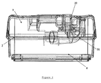
- a tank according to the invention comprises a lid 1, a sealing element 2, an air inlet nozzle 31 and an air outlet nozzle 32, and a tank 4 for containing a fluid.
- the block diagram of the figure 1 allows to explain the different interactions between the parts constituting the tank.
- FC1 The cover 1 is directly in contact with a flexible connector of an appliance to seal between the lid 1 and a gas exhaust mouth of the appliance.
- the connector is in compression when the tank is assembled and placed on the device.
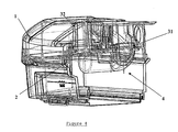
- FC2 and FC2 ' The cover 1 is connected to the end pieces (31, 32) by at least one hook adapted to cooperate with a complementary element carried by the cover 1.
- the end pieces (31, 32) are connected by a connecting flange 33 to form a single piece 3.
- the connecting flange 33 has a locking hook 34, as well as different stops (35, 36) to ensure its positioning and its stability with respect to all of the tank.
- the lid 1 is connected to the inlet end of the gas stream 31 via an internal spacer of the sealing element 2.
- the inlet end of the gas stream 31 passes through the internal spacer of the sealing element 2 through an orifice 212, and the outlet end of the gas stream 32 passes through the internal spacer of the sealing element 2 through an orifice 214 and is directly in contact with the cover 1 at the An outlet orifice 12.
- the outlet end of the gas stream 32 is advantageously extended by a vertical rectilinear section 321, which passes through the orifice 214 of the inner spacer and the outlet orifice 12 of the lid.
- the seal between the orifice 12 and the rectilinear section 321 of the tip 32 can be provided by the presence of an O-ring, for example.
- FC3 The cover 1 is connected to the sealing element 2 mainly through a groove 221 carried by a peripheral seal 22 of the sealing element 2.
- This groove 221 thus provides both sealing and positioning of the sealing element 2 on the cover 1.
- the reservoir has a curved shape which ensures that the peripheral seal 22 can be positioned in one way.
- the cooperation between the cover 1 and the sealing element 2 also makes it possible to form a sealed circuit delimited by a partition 14 of the cover 1 which is inserted into a groove 211 formed on the internal spacer 21. It is made of even with a partition 15 which is sinking into a groove 213 to reinforce the seal around the outlet end 32.
- the keying is again ensured by the fact that the grooves 211 and 213 do not have the same shape, but have a shape complementary to that of the walls 14 and 15.
- FC4 Each of the end pieces (31, 32) is preferably connected to the sealing element 2 by fitting.
- the inlet end of the gas stream 31 passes through the orifice 212 while the outlet end of the gas stream 32 passes through an orifice 214.
- the coding is notably ensured by the fact that the end pieces (31, 32) form only a single piece 3 that it is possible to fit into the orifices (212, 214) in one way.
- the end pieces (31, 32) assembled to the sealing element 2 it is possible to fix them to the cover 1 only in one way because of the position of the elements (34, 35, 36).
- the use of a flexible material, polymer type is therefore advantageous to ensure sealing and maintenance of the tips.
- the connecting flange 33 is positioned under the internal spacer 21 when the cover 1, the element 2 and the piece of nozzle 3 are assembled so that the tip piece 3 does not weigh on the inner spacer 21 and can also serve as a support.
- FC5 The tank 4 is mainly composed of a bottom 42, preferably metal, and a side wall 41, which connects the tank to the sealing element 2 through a groove 222.
- the peripheral seal 22 of the sealing element 2 is in compression between the lid 1 and the tank 4 when the tank is assembled.
- FC6 The tip piece 3 is advantageously in contact with the tray 4.
- the stop 36 of the connecting flange 33 of the single piece of bits 3 is able to bear against a protruding element 411 of the side wall 41 of the tray 4.
- the stop 36 is inserted between two wedges 412.
- the tip piece 3 is then completely immobilized when the reservoir is assembled.
- the inlet end of the gas stream 31 is preferably formed of an elbow section 311 extended by a rectilinear section 312 so that the gas flow arrives towards the center of the reservoir to optimize the flow of gas and that it is sufficiently charged with fluid before reaching the outlet end 32.
- FC7 The lid and the tray can also be directly in contact, for example by hinges 414 and a clip (13, 431) formed by a tongue 13 carried by the lid and a loop 413 carried by the tray 4. This secures the l assembly of the tank and prevents it from decomposing when transported assembled, for example to be placed in position on a device able to receive it.
- FC8 Finally, the patient circuit is connected to the outlet end 32 thanks to its rectilinear section 321 through the outlet orifice 12.
- the positioning of the patient circuit and the seal may for example be provided by a tight fitting, or a screwing of the patient circuit to the orifice 12 or the rectilinear section 321.
Priority Applications (4)
| Application Number | Priority Date | Filing Date | Title |
|---|---|---|---|
| DE2010105292 DE11005292T1 (de) | 2011-06-29 | 2011-06-29 | Behälter für Gerät zur Atmungsunterstützung |
| EP11005292A EP2540335A1 (de) | 2011-06-29 | 2011-06-29 | Behälter für Gerät zur Atmungsunterstützung |
| EP12738514.4A EP2726134A1 (de) | 2011-06-29 | 2012-06-22 | Reservoir für eine atemhilfevorrichtung |
| PCT/FR2012/051434 WO2013001216A1 (fr) | 2011-06-29 | 2012-06-22 | Reservoir pour appareil d'assistance respiratoire |
Applications Claiming Priority (1)
| Application Number | Priority Date | Filing Date | Title |
|---|---|---|---|
| EP11005292A EP2540335A1 (de) | 2011-06-29 | 2011-06-29 | Behälter für Gerät zur Atmungsunterstützung |
Publications (1)
| Publication Number | Publication Date |
|---|---|
| EP2540335A1 true EP2540335A1 (de) | 2013-01-02 |
Family
ID=46579175
Family Applications (2)
| Application Number | Title | Priority Date | Filing Date |
|---|---|---|---|
| EP11005292A Withdrawn EP2540335A1 (de) | 2011-06-29 | 2011-06-29 | Behälter für Gerät zur Atmungsunterstützung |
| EP12738514.4A Withdrawn EP2726134A1 (de) | 2011-06-29 | 2012-06-22 | Reservoir für eine atemhilfevorrichtung |
Family Applications After (1)
| Application Number | Title | Priority Date | Filing Date |
|---|---|---|---|
| EP12738514.4A Withdrawn EP2726134A1 (de) | 2011-06-29 | 2012-06-22 | Reservoir für eine atemhilfevorrichtung |
Country Status (3)
| Country | Link |
|---|---|
| EP (2) | EP2540335A1 (de) |
| DE (1) | DE11005292T1 (de) |
| WO (1) | WO2013001216A1 (de) |
Cited By (7)
| Publication number | Priority date | Publication date | Assignee | Title |
|---|---|---|---|---|
| EP3153203A1 (de) * | 2012-09-07 | 2017-04-12 | Fisher&Paykel Healthcare Limited | Befeuchtungskammer für eine atemhilfsvorrichtung |
| EP3406289A1 (de) * | 2017-05-24 | 2018-11-28 | Air Liquide Medical Systems | Verbesserter wasserbehälter für einen beheizten gasbefeuchter, der durch ein medizinisches beatmungsgerät gespeist wird |
| US10342950B2 (en) | 2013-03-15 | 2019-07-09 | ResMed Pty Ltd | Humidifier reservoir |
| CN111068157A (zh) * | 2014-01-30 | 2020-04-28 | 费雪派克医疗保健有限公司 | 具有液体约束的呼吸辅助设备 |
| US11013881B2 (en) | 2013-03-15 | 2021-05-25 | ResMed Pty Ltd | Humidifier reservoir |
| WO2021116235A1 (fr) | 2019-12-13 | 2021-06-17 | Sleepinnov Technology | Dispositif d'humidification pour appareil respiratoire à pression positive |
| US11135393B2 (en) | 2016-05-02 | 2021-10-05 | Fisher & Paykel Healthcare Limited | Humidification chamber and chamber seal for a respiratory assistance apparatus |
Families Citing this family (2)
| Publication number | Priority date | Publication date | Assignee | Title |
|---|---|---|---|---|
| FR3056111A1 (fr) * | 2016-09-16 | 2018-03-23 | Sefam | Dispositif de decontamination et de desinfection pour appareil de ventilation a pression positive |
| GB2617147A (en) | 2022-03-30 | 2023-10-04 | Univ Hospital Southampton Nhs Foundation Trust | Gas conservation apparatus |
Citations (4)
| Publication number | Priority date | Publication date | Assignee | Title |
|---|---|---|---|---|
| US5564415A (en) * | 1995-06-07 | 1996-10-15 | Lifecare International, Inc. | Humidifier for a ventilator |
| WO2002013898A2 (en) * | 2000-08-14 | 2002-02-21 | Taga Medical Technologies, Inc. | Cpap humidifier |
| WO2002066107A1 (en) * | 2001-02-16 | 2002-08-29 | Resmed Limited | Air pressure signal monitoring in apparatus for treating sleep disordered breathing |
| WO2010031126A1 (en) * | 2008-09-17 | 2010-03-25 | Resmed Ltd | Humidification of respiratory gases |
Family Cites Families (1)
| Publication number | Priority date | Publication date | Assignee | Title |
|---|---|---|---|---|
| US7677246B2 (en) * | 2005-09-23 | 2010-03-16 | Ric Investments, Llc | Modular pressure support system |
-
2011
- 2011-06-29 EP EP11005292A patent/EP2540335A1/de not_active Withdrawn
- 2011-06-29 DE DE2010105292 patent/DE11005292T1/de active Pending
-
2012
- 2012-06-22 EP EP12738514.4A patent/EP2726134A1/de not_active Withdrawn
- 2012-06-22 WO PCT/FR2012/051434 patent/WO2013001216A1/fr active Application Filing
Patent Citations (4)
| Publication number | Priority date | Publication date | Assignee | Title |
|---|---|---|---|---|
| US5564415A (en) * | 1995-06-07 | 1996-10-15 | Lifecare International, Inc. | Humidifier for a ventilator |
| WO2002013898A2 (en) * | 2000-08-14 | 2002-02-21 | Taga Medical Technologies, Inc. | Cpap humidifier |
| WO2002066107A1 (en) * | 2001-02-16 | 2002-08-29 | Resmed Limited | Air pressure signal monitoring in apparatus for treating sleep disordered breathing |
| WO2010031126A1 (en) * | 2008-09-17 | 2010-03-25 | Resmed Ltd | Humidification of respiratory gases |
Cited By (31)
| Publication number | Priority date | Publication date | Assignee | Title |
|---|---|---|---|---|
| EP3831433A1 (de) * | 2012-09-07 | 2021-06-09 | Fisher & Paykel Healthcare Limited | Befeuchtungskammer zum befeuchten von gasen |
| US10004871B2 (en) | 2012-09-07 | 2018-06-26 | Fisher & Paykel Healthcare Limited | Humidification chamber for a respiratory assistance apparatus |
| US10058673B1 (en) | 2012-09-07 | 2018-08-28 | Fisher & Paykel Healthcare Limited | Humidification chamber for a respiratory assistance apparatus |
| US10112028B2 (en) | 2012-09-07 | 2018-10-30 | Fisher & Paykel Healthcare Limited | Humidification chamber for a respiratory assistance apparatus |
| US11904099B2 (en) | 2012-09-07 | 2024-02-20 | Fisher & Paykel Healthcare Limited | Humidification chamber for a respiratory assistance apparatus |
| EP3153203A1 (de) * | 2012-09-07 | 2017-04-12 | Fisher&Paykel Healthcare Limited | Befeuchtungskammer für eine atemhilfsvorrichtung |
| US10238829B2 (en) | 2012-09-07 | 2019-03-26 | Fisher & Paykel Healthcare Limited | Humidification chamber for a respiratory assistance apparatus |
| US11058846B2 (en) | 2012-09-07 | 2021-07-13 | Fisher & Paykel Healthcare Limited | Humidification chamber for a respiratory assistance apparatus |
| US20220273905A1 (en) * | 2013-03-15 | 2022-09-01 | ResMed Pty Ltd | Humidifier reservoir |
| US11504496B2 (en) | 2013-03-15 | 2022-11-22 | ResMed Pty Ltd | Humidifier reservoir |
| EP2968829B1 (de) * | 2013-03-15 | 2021-04-21 | ResMed Pty Ltd | Wasserreservoirs und verfahren zur überfüllungsvermeidung in einem befeuchterreservoir |
| US11013881B2 (en) | 2013-03-15 | 2021-05-25 | ResMed Pty Ltd | Humidifier reservoir |
| US11883605B2 (en) | 2013-03-15 | 2024-01-30 | ResMed Pty Ltd | Humidifier reservoir |
| US11672940B2 (en) | 2013-03-15 | 2023-06-13 | ResMed Pty Ltd | Humidifier reservoir |
| US11666727B2 (en) | 2013-03-15 | 2023-06-06 | ResMed Pty Ltd | Medical treatment apparatus and water reservoir for same |
| US10342950B2 (en) | 2013-03-15 | 2019-07-09 | ResMed Pty Ltd | Humidifier reservoir |
| US11565075B2 (en) | 2013-03-15 | 2023-01-31 | ResMed Pty Ltd | Humidifier reservoir |
| US11298499B2 (en) | 2013-03-15 | 2022-04-12 | ResMed Pty Ltd | Humidifier reservoir |
| US11311696B2 (en) | 2013-03-15 | 2022-04-26 | ResMed Pty Ltd | Humidifier reservoir |
| US11357948B2 (en) | 2013-03-15 | 2022-06-14 | ResMed Pty Ltd | Humidifier reservoir |
| US11357947B2 (en) | 2013-03-15 | 2022-06-14 | ResMed Pty Ltd | Humidifier reservoir |
| US11565076B2 (en) | 2013-03-15 | 2023-01-31 | ResMed Pty Ltd | Medical treatment apparatus and water reservoir for same |
| US11464935B2 (en) | 2013-03-15 | 2022-10-11 | ResMed Pty Ltd | Respiratory pressure therapy device having dock configured to alternatively receive a water reservoir or an end cap |
| US11497879B2 (en) | 2013-03-15 | 2022-11-15 | ResMed Pty Ltd | Humidifier reservoir |
| US10688271B2 (en) | 2013-03-15 | 2020-06-23 | ResMed Pty Ltd | Humidifier reservoir |
| CN111068157A (zh) * | 2014-01-30 | 2020-04-28 | 费雪派克医疗保健有限公司 | 具有液体约束的呼吸辅助设备 |
| US11135393B2 (en) | 2016-05-02 | 2021-10-05 | Fisher & Paykel Healthcare Limited | Humidification chamber and chamber seal for a respiratory assistance apparatus |
| FR3066698A1 (fr) * | 2017-05-24 | 2018-11-30 | Air Liquide Medical Systems | Reservoir d’eau ameliore pour un humidificateur de gaz chauffant alimente par un ventilateur medical |
| EP3406289A1 (de) * | 2017-05-24 | 2018-11-28 | Air Liquide Medical Systems | Verbesserter wasserbehälter für einen beheizten gasbefeuchter, der durch ein medizinisches beatmungsgerät gespeist wird |
| FR3104443A1 (fr) | 2019-12-13 | 2021-06-18 | SleepInnov Technology | Dispositif d'humidification pour appareil respiratoire à pression positive |
| WO2021116235A1 (fr) | 2019-12-13 | 2021-06-17 | Sleepinnov Technology | Dispositif d'humidification pour appareil respiratoire à pression positive |
Also Published As
| Publication number | Publication date |
|---|---|
| DE11005292T1 (de) | 2013-07-25 |
| EP2726134A1 (de) | 2014-05-07 |
| WO2013001216A1 (fr) | 2013-01-03 |
Similar Documents
| Publication | Publication Date | Title |
|---|---|---|
| EP2540335A1 (de) | Behälter für Gerät zur Atmungsunterstützung | |
| FR2725373A1 (fr) | Chambre d'humidificateur | |
| EP3406289B1 (de) | Verbesserter wasserbehälter für einen beheizten gasbefeuchter, der durch ein medizinisches beatmungsgerät gespeist wird | |
| FR3019989B1 (fr) | Diffuseur de fumee et atomiseur | |
| FR2976050A1 (fr) | Installation de chauffage comprenant un appareil de chauffage a bois, une sortie de batiment et un conduit de liaison | |
| CA2649765A1 (fr) | Chauffe-eau plat | |
| FR2895492A3 (fr) | Dispositif pour la collecte d'eau de condensation ou d'eau de pluie a l'interieur d'une chaudiere a gaz. | |
| FR2565326A1 (fr) | Dispositif d'evacuation du condensat pour un appareil a combustion | |
| EP2417995B1 (de) | System zur Atmungsunterstützung | |
| EP4072637A1 (de) | Befeuchtungsvorrichtung für ein atemgerät mit positivem atemwegsdruck | |
| EP3127504A1 (de) | Vorrichtung zum reinigen und trocknen von artikeln | |
| JP3102413B2 (ja) | 電気貯湯容器 | |
| EP3406288B1 (de) | Einheit aus gasbefeuchter und medizinischem beatmungsgerät mit wasserbehälter mit verbesserter abdichtung | |
| CN218106990U (zh) | 一种自动供水的软化水水箱 | |
| FR2923148A1 (fr) | Systeme de sechage corporel a air chaud | |
| BE1018968A3 (fr) | Ensemble d'un couvercle et d'un organe de liaison destine a faire partie d'un pistolet a fluide. | |
| EP2916965A1 (de) | Kartusche mit eingeplanter obsoleszenz zur erzeugung und ausgabe eines aerosols und sprühvorrichtung damit | |
| FR3000787A1 (fr) | Chauffe-eau thermodynamique | |
| JP2003307342A (ja) | 給湯装置 | |
| FR2977470A1 (fr) | Systeme de mesure de pression pour ventilateur medical | |
| JP2013007213A (ja) | 加熱器取付座付き蓋体 | |
| WO2024084175A1 (fr) | Base de diffusion de vapeur pour un appareil électroménager | |
| WO2024084174A1 (fr) | Accessoire de diffusion de vapeur | |
| WO2024084172A1 (fr) | Ensemble pour un accessoire de diffusion de vapeur | |
| WO2024084173A1 (fr) | Organe de connexion pour relier un accessoire de diffusion de vapeur à une base de diffusion de vapeur |
Legal Events
| Date | Code | Title | Description |
|---|---|---|---|
| PUAI | Public reference made under article 153(3) epc to a published international application that has entered the european phase |
Free format text: ORIGINAL CODE: 0009012 |
|
| AK | Designated contracting states |
Kind code of ref document: A1 Designated state(s): AL AT BE BG CH CY CZ DE DK EE ES FI FR GB GR HR HU IE IS IT LI LT LU LV MC MK MT NL NO PL PT RO RS SE SI SK SM TR |
|
| AX | Request for extension of the european patent |
Extension state: BA ME |
|
| REG | Reference to a national code |
Ref country code: DE Ref legal event code: R082 Representative=s name: RAU, SCHNECK & HUEBNER PATENTANWAELTE RECHTSAN, DE Ref country code: DE Ref legal event code: R082 Representative=s name: RAU, SCHNECK & HUEBNER PATENT- UND RECHTSANWAE, DE Ref country code: DE Ref legal event code: R082 |
|
| REG | Reference to a national code |
Ref country code: DE Ref legal event code: R210 Effective date: 20130725 |
|
| 17P | Request for examination filed |
Effective date: 20130628 |
|
| STAA | Information on the status of an ep patent application or granted ep patent |
Free format text: STATUS: THE APPLICATION IS DEEMED TO BE WITHDRAWN |
|
| 18D | Application deemed to be withdrawn |
Effective date: 20150106 |