EP4175847B1 - Ladesystem für materialhandhabungsfahrzeug mit einer bodenmontierten ladeplatte - Google Patents
Ladesystem für materialhandhabungsfahrzeug mit einer bodenmontierten ladeplatte Download PDFInfo
- Publication number
- EP4175847B1 EP4175847B1 EP21746284.5A EP21746284A EP4175847B1 EP 4175847 B1 EP4175847 B1 EP 4175847B1 EP 21746284 A EP21746284 A EP 21746284A EP 4175847 B1 EP4175847 B1 EP 4175847B1
- Authority
- EP
- European Patent Office
- Prior art keywords
- charging
- floor
- vehicle
- materials handling
- handling vehicle
- Prior art date
- Legal status (The legal status is an assumption and is not a legal conclusion. Google has not performed a legal analysis and makes no representation as to the accuracy of the status listed.)
- Active
Links
Images




Classifications
-
- B—PERFORMING OPERATIONS; TRANSPORTING
- B66—HOISTING; LIFTING; HAULING
- B66F—HOISTING, LIFTING, HAULING OR PUSHING, NOT OTHERWISE PROVIDED FOR, e.g. DEVICES WHICH APPLY A LIFTING OR PUSHING FORCE DIRECTLY TO THE SURFACE OF A LOAD
- B66F9/00—Devices for lifting or lowering bulky or heavy goods for loading or unloading purposes
- B66F9/06—Devices for lifting or lowering bulky or heavy goods for loading or unloading purposes movable, with their loads, on wheels or the like, e.g. fork-lift trucks
- B66F9/075—Constructional features or details
- B66F9/07504—Accessories, e.g. for towing, charging, locking
-
- B—PERFORMING OPERATIONS; TRANSPORTING
- B60—VEHICLES IN GENERAL
- B60L—PROPULSION OF ELECTRICALLY-PROPELLED VEHICLES; SUPPLYING ELECTRIC POWER FOR AUXILIARY EQUIPMENT OF ELECTRICALLY-PROPELLED VEHICLES; ELECTRODYNAMIC BRAKE SYSTEMS FOR VEHICLES IN GENERAL; MAGNETIC SUSPENSION OR LEVITATION FOR VEHICLES; MONITORING OPERATING VARIABLES OF ELECTRICALLY-PROPELLED VEHICLES; ELECTRIC SAFETY DEVICES FOR ELECTRICALLY-PROPELLED VEHICLES
- B60L53/00—Methods of charging batteries, specially adapted for electric vehicles; Charging stations or on-board charging equipment therefor; Exchange of energy storage elements in electric vehicles
- B60L53/10—Methods of charging batteries, specially adapted for electric vehicles; Charging stations or on-board charging equipment therefor; Exchange of energy storage elements in electric vehicles characterised by the energy transfer between the charging station and the vehicle
- B60L53/14—Conductive energy transfer
- B60L53/16—Connectors, e.g. plugs or sockets, specially adapted for charging electric vehicles
-
- B—PERFORMING OPERATIONS; TRANSPORTING
- B60—VEHICLES IN GENERAL
- B60L—PROPULSION OF ELECTRICALLY-PROPELLED VEHICLES; SUPPLYING ELECTRIC POWER FOR AUXILIARY EQUIPMENT OF ELECTRICALLY-PROPELLED VEHICLES; ELECTRODYNAMIC BRAKE SYSTEMS FOR VEHICLES IN GENERAL; MAGNETIC SUSPENSION OR LEVITATION FOR VEHICLES; MONITORING OPERATING VARIABLES OF ELECTRICALLY-PROPELLED VEHICLES; ELECTRIC SAFETY DEVICES FOR ELECTRICALLY-PROPELLED VEHICLES
- B60L53/00—Methods of charging batteries, specially adapted for electric vehicles; Charging stations or on-board charging equipment therefor; Exchange of energy storage elements in electric vehicles
- B60L53/30—Constructional details of charging stations
-
- B—PERFORMING OPERATIONS; TRANSPORTING
- B60—VEHICLES IN GENERAL
- B60L—PROPULSION OF ELECTRICALLY-PROPELLED VEHICLES; SUPPLYING ELECTRIC POWER FOR AUXILIARY EQUIPMENT OF ELECTRICALLY-PROPELLED VEHICLES; ELECTRODYNAMIC BRAKE SYSTEMS FOR VEHICLES IN GENERAL; MAGNETIC SUSPENSION OR LEVITATION FOR VEHICLES; MONITORING OPERATING VARIABLES OF ELECTRICALLY-PROPELLED VEHICLES; ELECTRIC SAFETY DEVICES FOR ELECTRICALLY-PROPELLED VEHICLES
- B60L53/00—Methods of charging batteries, specially adapted for electric vehicles; Charging stations or on-board charging equipment therefor; Exchange of energy storage elements in electric vehicles
- B60L53/30—Constructional details of charging stations
- B60L53/35—Means for automatic or assisted adjustment of the relative position of charging devices and vehicles
- B60L53/36—Means for automatic or assisted adjustment of the relative position of charging devices and vehicles by positioning the vehicle
-
- B—PERFORMING OPERATIONS; TRANSPORTING
- B66—HOISTING; LIFTING; HAULING
- B66F—HOISTING, LIFTING, HAULING OR PUSHING, NOT OTHERWISE PROVIDED FOR, e.g. DEVICES WHICH APPLY A LIFTING OR PUSHING FORCE DIRECTLY TO THE SURFACE OF A LOAD
- B66F9/00—Devices for lifting or lowering bulky or heavy goods for loading or unloading purposes
- B66F9/06—Devices for lifting or lowering bulky or heavy goods for loading or unloading purposes movable, with their loads, on wheels or the like, e.g. fork-lift trucks
- B66F9/075—Constructional features or details
- B66F9/07586—Suspension or mounting of wheels on chassis
-
- H—ELECTRICITY
- H02—GENERATION; CONVERSION OR DISTRIBUTION OF ELECTRIC POWER
- H02J—ELECTRIC POWER NETWORKS; CIRCUIT ARRANGEMENTS OR SYSTEMS FOR SUPPLYING OR DISTRIBUTING ELECTRIC POWER; SYSTEMS FOR STORING ELECTRIC ENERGY
- H02J50/00—Circuit arrangements or systems for wireless supply or distribution of electric power
- H02J50/005—Mechanical details of housing or structure aiming to accommodate the power transfer means, e.g. mechanical integration of coils, antennas or transducers into emitting or receiving devices
-
- H—ELECTRICITY
- H02—GENERATION; CONVERSION OR DISTRIBUTION OF ELECTRIC POWER
- H02J—ELECTRIC POWER NETWORKS; CIRCUIT ARRANGEMENTS OR SYSTEMS FOR SUPPLYING OR DISTRIBUTING ELECTRIC POWER; SYSTEMS FOR STORING ELECTRIC ENERGY
- H02J50/00—Circuit arrangements or systems for wireless supply or distribution of electric power
- H02J50/10—Circuit arrangements or systems for wireless supply or distribution of electric power using inductive coupling
-
- B—PERFORMING OPERATIONS; TRANSPORTING
- B60—VEHICLES IN GENERAL
- B60L—PROPULSION OF ELECTRICALLY-PROPELLED VEHICLES; SUPPLYING ELECTRIC POWER FOR AUXILIARY EQUIPMENT OF ELECTRICALLY-PROPELLED VEHICLES; ELECTRODYNAMIC BRAKE SYSTEMS FOR VEHICLES IN GENERAL; MAGNETIC SUSPENSION OR LEVITATION FOR VEHICLES; MONITORING OPERATING VARIABLES OF ELECTRICALLY-PROPELLED VEHICLES; ELECTRIC SAFETY DEVICES FOR ELECTRICALLY-PROPELLED VEHICLES
- B60L2200/00—Type of vehicles
- B60L2200/36—Vehicles designed to transport cargo, e.g. trucks
-
- B—PERFORMING OPERATIONS; TRANSPORTING
- B60—VEHICLES IN GENERAL
- B60L—PROPULSION OF ELECTRICALLY-PROPELLED VEHICLES; SUPPLYING ELECTRIC POWER FOR AUXILIARY EQUIPMENT OF ELECTRICALLY-PROPELLED VEHICLES; ELECTRODYNAMIC BRAKE SYSTEMS FOR VEHICLES IN GENERAL; MAGNETIC SUSPENSION OR LEVITATION FOR VEHICLES; MONITORING OPERATING VARIABLES OF ELECTRICALLY-PROPELLED VEHICLES; ELECTRIC SAFETY DEVICES FOR ELECTRICALLY-PROPELLED VEHICLES
- B60L2200/00—Type of vehicles
- B60L2200/40—Working vehicles
- B60L2200/42—Fork lift trucks
-
- B—PERFORMING OPERATIONS; TRANSPORTING
- B60—VEHICLES IN GENERAL
- B60L—PROPULSION OF ELECTRICALLY-PROPELLED VEHICLES; SUPPLYING ELECTRIC POWER FOR AUXILIARY EQUIPMENT OF ELECTRICALLY-PROPELLED VEHICLES; ELECTRODYNAMIC BRAKE SYSTEMS FOR VEHICLES IN GENERAL; MAGNETIC SUSPENSION OR LEVITATION FOR VEHICLES; MONITORING OPERATING VARIABLES OF ELECTRICALLY-PROPELLED VEHICLES; ELECTRIC SAFETY DEVICES FOR ELECTRICALLY-PROPELLED VEHICLES
- B60L2200/00—Type of vehicles
- B60L2200/40—Working vehicles
- B60L2200/44—Industrial trucks or floor conveyors
-
- Y—GENERAL TAGGING OF NEW TECHNOLOGICAL DEVELOPMENTS; GENERAL TAGGING OF CROSS-SECTIONAL TECHNOLOGIES SPANNING OVER SEVERAL SECTIONS OF THE IPC; TECHNICAL SUBJECTS COVERED BY FORMER USPC CROSS-REFERENCE ART COLLECTIONS [XRACs] AND DIGESTS
- Y02—TECHNOLOGIES OR APPLICATIONS FOR MITIGATION OR ADAPTATION AGAINST CLIMATE CHANGE
- Y02P—CLIMATE CHANGE MITIGATION TECHNOLOGIES IN THE PRODUCTION OR PROCESSING OF GOODS
- Y02P90/00—Enabling technologies with a potential contribution to greenhouse gas [GHG] emissions mitigation
- Y02P90/60—Electric or hybrid propulsion means for production processes
-
- Y—GENERAL TAGGING OF NEW TECHNOLOGICAL DEVELOPMENTS; GENERAL TAGGING OF CROSS-SECTIONAL TECHNOLOGIES SPANNING OVER SEVERAL SECTIONS OF THE IPC; TECHNICAL SUBJECTS COVERED BY FORMER USPC CROSS-REFERENCE ART COLLECTIONS [XRACs] AND DIGESTS
- Y02—TECHNOLOGIES OR APPLICATIONS FOR MITIGATION OR ADAPTATION AGAINST CLIMATE CHANGE
- Y02T—CLIMATE CHANGE MITIGATION TECHNOLOGIES RELATED TO TRANSPORTATION
- Y02T10/00—Road transport of goods or passengers
- Y02T10/60—Other road transportation technologies with climate change mitigation effect
- Y02T10/70—Energy storage systems for electromobility, e.g. batteries
-
- Y—GENERAL TAGGING OF NEW TECHNOLOGICAL DEVELOPMENTS; GENERAL TAGGING OF CROSS-SECTIONAL TECHNOLOGIES SPANNING OVER SEVERAL SECTIONS OF THE IPC; TECHNICAL SUBJECTS COVERED BY FORMER USPC CROSS-REFERENCE ART COLLECTIONS [XRACs] AND DIGESTS
- Y02—TECHNOLOGIES OR APPLICATIONS FOR MITIGATION OR ADAPTATION AGAINST CLIMATE CHANGE
- Y02T—CLIMATE CHANGE MITIGATION TECHNOLOGIES RELATED TO TRANSPORTATION
- Y02T10/00—Road transport of goods or passengers
- Y02T10/60—Other road transportation technologies with climate change mitigation effect
- Y02T10/7072—Electromobility specific charging systems or methods for batteries, ultracapacitors, supercapacitors or double-layer capacitors
-
- Y—GENERAL TAGGING OF NEW TECHNOLOGICAL DEVELOPMENTS; GENERAL TAGGING OF CROSS-SECTIONAL TECHNOLOGIES SPANNING OVER SEVERAL SECTIONS OF THE IPC; TECHNICAL SUBJECTS COVERED BY FORMER USPC CROSS-REFERENCE ART COLLECTIONS [XRACs] AND DIGESTS
- Y02—TECHNOLOGIES OR APPLICATIONS FOR MITIGATION OR ADAPTATION AGAINST CLIMATE CHANGE
- Y02T—CLIMATE CHANGE MITIGATION TECHNOLOGIES RELATED TO TRANSPORTATION
- Y02T90/00—Enabling technologies or technologies with a potential or indirect contribution to GHG emissions mitigation
- Y02T90/10—Technologies relating to charging of electric vehicles
- Y02T90/12—Electric charging stations
-
- Y—GENERAL TAGGING OF NEW TECHNOLOGICAL DEVELOPMENTS; GENERAL TAGGING OF CROSS-SECTIONAL TECHNOLOGIES SPANNING OVER SEVERAL SECTIONS OF THE IPC; TECHNICAL SUBJECTS COVERED BY FORMER USPC CROSS-REFERENCE ART COLLECTIONS [XRACs] AND DIGESTS
- Y02—TECHNOLOGIES OR APPLICATIONS FOR MITIGATION OR ADAPTATION AGAINST CLIMATE CHANGE
- Y02T—CLIMATE CHANGE MITIGATION TECHNOLOGIES RELATED TO TRANSPORTATION
- Y02T90/00—Enabling technologies or technologies with a potential or indirect contribution to GHG emissions mitigation
- Y02T90/10—Technologies relating to charging of electric vehicles
- Y02T90/14—Plug-in electric vehicles
Definitions
- Materials handling vehicles are utilized to move materials into, out of, and throughout a warehouse environment.
- materials handling vehicles include tuggers, forklift trucks, hand and motor driven pallet trucks, and other types of materials handling vehicles.
- Materials handling vehicles can be configured as automated guided vehicles or as vehicles that manually navigate through a warehouse environment.
- the vehicle may be adapted for localization within the environment. That is, the materials handling vehicle can be adapted with sensors and processors for localization, i.e., for determining the location and, optionally, the pose of the vehicle within the environment.
- the sensors can be configured to detect objects in the environment and the localization can be dependent upon features extracted from such detected objects. Systems of this nature are described in, for example, US PG Pub.
- JP 2009038858 A discloses a materials handling vehicle charging system according to the preamble of claim 1, which provides a running controller in a running vehicle having inner and outer wheels driven independently.
- An outer wheel torque command value is determined by PI control within the range of an outer wheel allowable torque which is set based on the outer wheel speed when the running vehicle turns.
- the outer wheel torque command value is set as an inner wheel allowable torque.
- An inner wheel torque command value is determined by PI control within the range of the inner wheel allowable torque.
- CN 109572460 A discloses a wheeled robot automatic recharging method and devices.
- the wheeled robot is provided with a wireless locating module, first communication module and wheel.
- the wheeled robot can be charged by an automatic charge device.
- the automatic charge device is provided with wheel fixed module, second communication module and charging part.
- US 2019/263278 A1 discloses a vehicle connection device for electrically connecting a vehicle contact unit to a ground contact unit of an electric charging infrastructure, having a pneumatically operated contacting actuator adapted to move the vehicle contact unit, and at least one air outlet for blowing the ground contact unit free.
- US 2012/282065 A1 discloses a system for periodically charging an electrically powered automated guided vehicle.
- the charging station includes a charging arm which is selectively movable between a stowed position and a charge position in which the charging arm engages with the automated guided vehicle to perform a charging operation.
- the charging station is dimensioned and positioned so as to be positioned underneath a bottom surface of a platform connected to the automated guided vehicle and between a side edge of the platform and the automated guided vehicle.
- a materials handling vehicle charging system including a materials handling vehicle and a charging station.
- the materials handling vehicle includes a materials handling mechanism, a battery, a drive mechanism powered by the battery, a central drive line extending between a leading end and a trailing end of the materials handling vehicle, a steerable drive wheel motively coupled to the drive mechanism, and a pair of load wheels positioned on opposite sides of the central drive line.
- the steerable drive wheel is aligned with the central drive line and defines a drive wheel track width W.
- the pair of load wheels are positioned on opposite sides of the central drive line and define a load wheel gap G between the pair of load wheels that is larger than the drive wheel track width W.
- the materials handling vehicle is characterised by comprising a vehicle-side charging contact assembly defining a vehicle-side contact profile, vehicle-side charging circuitry coupling the vehicle-side charging contact assembly to the battery.
- the charging station includes a floor-mounted charging plate assembly, a battery charger, and floor-side charging circuitry coupling the floor-mounted charging plate assembly to the battery charger.
- the floor-mounted charging plate assembly includes a pair of floor-side charging contacts defining a floor-side contact profile that complements the vehicle-side contact profile of the vehicle-side charging contact assembly to enable direct contact transfer of charging current from the floor-side charging contacts to the vehicle-side charging contact assembly.
- the pair of floor-side charging contacts define an inner contact spacing S1 that is larger than the drive wheel track width W, and an outer contact spacing S2 that is larger than the inner contact spacing S 1 and smaller than the load wheel gap G to permit passage of the steerable drive wheel between the pair of floor-side charging contacts, followed by passage of the pair of load wheels outside of the pair of floor-side charging contacts, with vehicle movement along the central drive line.
- a materials handling vehicle charging system including a materials handling vehicle and a charging station.
- the materials handling vehicle includes a materials handling mechanism, a battery, a drive mechanism powered by the battery, a vehicle-side charging contact assembly defining a vehicle-side contact profile, and vehicle-side charging circuitry coupling the vehicle-side charging contacts to the battery.
- the charging station comprises a floor-mounted charging plate assembly, a battery charger, and floor-side charging circuitry coupling the floor-mounted charging plate assembly to the battery charger.
- the floor-mounted charging plate assembly includes a mounting platform, a multi-directional charging plate mounted to the mounting platform, and a pair of floor-side charging contacts carried by the multi-directional charging plate.
- the floor-side charging contacts define a floor-side contact profile that complements the vehicle-side contact profile of the vehicle-side charging contact assembly to enable direct contact transfer of charging current from the floor-side charging contacts to the vehicle-side charging contact assembly.
- the multi-directional charging plate includes a charging plate footprint that is rotationally symmetric at a plurality of mounting positions about a rotational mounting axis orthogonal to a mounting plane defined by the mounting platform.
- the floor-mounted charging plate assembly includes a pair of floor-side charging contacts defining a floor-side contact profile that is configured to complement a vehicle-side contact profile of a target materials handling vehicle, to enable direct contact transfer of charging current from the floor-side charging contacts to the vehicle-side charging contact assembly.
- the pair of floor-side charging contacts define an inner contact spacing S 1 that is larger than a drive wheel track width W of the target materials handling vehicle, and an outer contact spacing S2 that is larger than the inner contact spacing S 1 and smaller than a load wheel gap G of the target materials handling vehicle, to permit passage of a steerable drive wheel of the target materials handling vehicle between the pair of floor-side charging contacts, followed by passage of a pair of load wheels of the target materials handling vehicle outside of the pair of floor-side charging contacts.
- a materials handling vehicle charging station including a floor-mounted charging plate assembly, a battery charger, and vehicle-side charging circuitry coupling the floor-mounted charging plate assembly to the battery charger.
- the floor-mounted charging plate assembly includes a pair of floor-side charging contacts defining a floor-side contact profile that is configured to complement a vehicle-side contact profile of a target materials handling vehicle, to enable direct contact transfer of charging current from the floor-side charging contacts to the vehicle-side charging contact assembly.
- the floor-mounted charging plate assembly includes a mounting platform and a multi-directional charging plate mounted to the mounting platform.
- the multi-directional charging plate carries the floor-side charging contacts and includes a charging plate footprint that is rotationally symmetric at a plurality of mounting positions about a rotational mounting axis orthogonal to a mounting plane defined by the mounting platform.
- a materials handling vehicle charging system comprising a materials handling vehicle 100 and a charging station 200.
- the materials handling vehicle 100 may include a materials handling mechanism 110, a battery 120, a drive mechanism 130 powered by the battery 120, a vehicle-side charging contact assembly 140 defining a vehicle-side contact profile 150, vehicle-side charging circuitry 160 coupling the vehicle-side charging contact assembly 140 to the battery 120, a central drive line 170 extending between a leading end 172 and a trailing end 174 of the materials handling vehicle 100, a steerable drive wheel 180 motively coupled to the drive mechanism 130, a pair of load wheels 190 positioned on opposite sides of the central drive line 170, and a charging control unit 184.
- the materials handling mechanism 110 is merely illustrated schematically in Fig. 1 , but may be provided in a variety of forms, depending primarily on the vehicle type.
- the materials handling mechanism 110 may be provided as a hitch, hook, latch, etc.
- the materials handling vehicle 100 is a forklift truck or a hand or motor-driven pallet truck
- the materials handling mechanism 110 may be provided as a pair of materials handling forks.
- the materials handling vehicle 100 may be a tugger, with a materials handling mechanism 110 in the form of a hitch or other towing assembly configured to pull a load from the trailing end 174 of the materials handling vehicle 100.
- the materials handling vehicle 100 may be any vehicle including a materials handling mechanism capable of handling materials, such as, for example, a forklift truck, a hand and motor driven pallet truck, and other types of materials handling vehicles.
- the steerable drive wheel 180 may be aligned with the central drive line 170, such that the steerable drive wheel 180 is positioned on the central drive line 170.
- the steerable drive wheel 180 may define a drive wheel track width W.
- the drive wheel track width W is at least about 40 mm. In one embodiment, the drive wheel track width W is about 75 mm but may vary depending on vehicle type. In many cases, it is contemplated that the drive wheel track width W is from about 40 mm to about 160 mm.
- the steerable drive wheel 180 may be positioned at the leading end 172 of the materials handling vehicle 100. In embodiments, the steerable drive wheel 180 may be positioned at the trailing end 174 of the materials handling vehicle 100.
- the drive mechanism 130 which is illustrated schematically in FIG. 1 , is motively coupled to the steerable drive wheel 180 to rotate the drive wheel 180.
- the drive mechanism 130 may be any known mechanism for effecting movement of a vehicle, such as, for example, a motor.
- the drive mechanism 130 is coupled to the battery 120 such that electrical current may be provided from the battery 120 to the drive mechanism 130, thereby powering the drive mechanism 130.
- the pair of load wheels 190 may be positioned on opposite sides of the central drive line 170.
- the materials handling vehicle 100 may include any number of load wheels 190, such as, for example, four load wheels.
- the load wheels 190 may be positioned on opposite sides of the central drive line 170 such that the load wheels 190 on one side of the central drive line 170 may be positioned adjacent one another, and the load wheels 190 on the other side of the central drive line 170 may be positioned adjacent one another.
- the load wheels 190 may be arranged such that each wheel rotates about a common axis.
- the pair of load wheels 190 may define a load wheel gap G between the pair of load wheels 190.
- the load wheel gap G may be the spacing or distance between the pair of load wheels 190.
- the load wheel gap G refers to the distance between the pair of load wheels 190 closest to the central drive line 170.
- the load wheel gap G may be larger than the drive wheel track width W.
- the load wheel gap G is from about, for example, 300 cm to about 1600 cm, and may particularly be about 500 cm.
- the pair of load wheels 190 may be positioned at the trailing end 174 of the materials handling vehicle 100, and the steerable drive wheel 180 may be positioned opposite the pair of load wheels 190 at the leading end 172. In embodiments, the pair of load wheels 190 may be positioned at the leading end 172 of the materials handling vehicle 100 with the drive wheel 180 being positioned at the trailing end 174.
- the vehicle-side charging contact assembly 140 may include a pair of vehicle-side charging contacts 144 that define the vehicle-side contact profile 150, vehicle-side data transfer contacts 188, and a vehicle-side actuator 142 coupled to the vehicle-side charging contacts 144.
- the vehicle-side charging contacts 144 may be coupled to the battery 120 via the vehicle-side charging circuitry 160, where the vehicle-side charging contacts 144 are configured to receive an electrical current and transmit the electrical current to the battery 120 via the vehicle-side charging circuitry 160.
- the vehicle-side actuator 142 may be configured to raise and lower the vehicle-side charging contacts 144 in and out of contact with the charging station 200 to selectively control transfer of electrical current to the battery 120.
- the vehicle-side charging contact assembly 140 may be positioned at the trailing end 174 of the materials handling vehicle 100. However, in embodiments, the vehicle-side charging contact assembly 140 may be positioned at the leading end 172 of the materials handling vehicle 100.
- the vehicle-side actuator 142 may lower the vehicle-side charging contacts 144 into contact with a pair of floor-side charging contacts 212 of the floor-mounted charging plate assembly 210, as will be described in more detail herein.
- the vehicle-side charging contact assembly 140 may further include vehicle-side data transfer circuitry 192, which is illustrated schematically in FIG. 1 , communicatively coupling the vehicle-side data transfer contacts 188 to the charging control unit 184.
- the vehicle-side data transfer contacts 188 may be positioned between the vehicle-side charging contacts 144.
- the data transfer contacts 188 are configured to transfer data to and from the charging station 200.
- the data transferred by the transfer contacts 188 may include battery data, vehicle data, charging station data, or any combination thereof.
- the data transfer contacts 188 may be coupled to the vehicle-side actuator 142 similarly to the vehicle-side charging contacts 144, so that the data transfer contacts 188 are raised and lowered with the vehicle-side charging contacts 144 in and out of contact with the charging station 200.
- the vehicle-side charging circuitry 160 coupling the vehicle-side charging contact assembly 140 to the battery 120 may be a plurality of wires configured to transfer electrical current to and from the vehicle-side charging contact assembly 140 and the battery 120. Specifically, the vehicle-side charging circuitry 160 may be coupled to the vehicle-side charging contacts 144 to transfer electrical current to the battery 120. Additionally, the vehicle-side charging circuitry 160 may be coupled to the vehicle-side actuator 142 to transfer electrical current from the battery 120 to the vehicle-side actuator 142 to actuate the vehicle-side actuator 142, raising and lowering the vehicle-side charging contacts 144.
- the materials handling vehicle 100 may further comprise sensors 186, which are merely illustrated schematically in Fig. 1 , that are communicatively coupled to the charging control unit 184.
- the sensors 186 may send signals to the charging control unit 184 indicative of the materials handling vehicle 100, and the vehicle-side charging contacts 144, being properly aligned over the multi-directional charging plate of the charging station 200.
- the charging control unit 184 may then detect whether the materials handling vehicle 100 and the vehicle-side charging contacts 144 are properly aligned over the multi-directional charging plate of the charging station 200, and, in response, may activate the vehicle-side actuator 142 to initiate charging.
- the sensors 186 may be proximity sensors, GPS sensors, or the like to determine the positioning of the materials handling vehicle 100. Proximity sensors may include, for example, inductive proximity sensors, capacitive proximity sensors, ultrasonic proximity sensors, or the like.
- a vehicle control system 112 may be communicatively coupled to the charging control unit 184 and the drive mechanism 130.
- the vehicle control system 112 may guide the materials handling vehicle 100 by providing signals to the drive mechanism 130, thereby moving and steering the drive wheel 180.
- the vehicle control system 112 may be communicatively coupled to a master vehicle controller 114 that provides signals to the vehicle control system 112 indicative of locations in which the vehicle control system 112 should guide the vehicle 100.
- the master vehicle controller 114 may be communicatively coupled to a plurality of materials handling vehicles 100 to coordinate movement of the plurality of materials handling vehicles 100 throughout a warehouse.
- the vehicle control system 112 may guide the materials handling vehicle 100 for performing tasks, such as moving materials throughout an environment.
- the charging control unit 184 may provide signals to the vehicle control system 112 indicative of a level of charge in the battery 120 of the materials handling vehicle 100.
- the vehicle control system 112 may send signals to the master vehicle controller 114 indicative of the level of charge in the battery 120, and the master vehicle controller 114, in response, may send signals to the vehicle control system 112 indicative of a location of a charging station 200.
- the location of the charging station 200 may be the nearest unoccupied charging station 200.
- the vehicle control system 112 may then alter the guidance of the materials handling vehicle 100 based on the signals received from the master vehicle controller 114.
- the vehicle control system 112 may provide signals to the drive mechanism 130 to guide the materials handling vehicle 100 toward the nearest charging station 200.
- the charging station 200 may include a floor-mounted charging plate assembly 210, a battery charger 220, and floor-side charging circuitry 230 coupling the floor-mounted charging plate assembly 210 to the battery charger 220.
- the charging station 200 includes a breaker box 224 coupled between the battery charger 220 and the floor-mounted charging plate assembly 210 such that the breaker box 224 may selectively disconnect electrical current from the battery charger 220 to the floor-mounted charging plate assembly 210.
- the floor-mounted charging plate assembly 210 may include a pair of floor-side charging contacts 212 defining a floor-side contact profile 214, and a pair of floor-side data transfer contacts 226.
- the floor-side contact profile 214 may complement the vehicle-side contact profile 150 of the vehicle-side charging contact assembly 140 to enable direct contact transfer of charging current from the floor-side charging contacts 212 to the vehicle-side charging contact assembly 140.
- the pair of floor-side charging contacts 212 define an inner contact spacing S1 and an outer contact spacing S2.
- the inner contact spacing S 1 is the spacing between an inner edge 213 of each of the pair of floor-side charging contacts 212.
- the inner contact spacing S1 is at least about 15 mm larger than the drive wheel track width W.
- the inner contact spacing S1 is from about 50 mm to about 400 mm, and may particularly be about 100 mm.
- the outer contact spacing S2 is the spacing between an outer edge 215 of each of the pair of floor-side charging contacts 212.
- the outer contact spacing S2 is at least about 70 mm larger than the inner contact spacing S1.
- the outer contact spacing S2 is from about 120 mm to about 500 mm, and may particularly be about 200 mm. Accordingly, the outer contact spacing S2 is larger than the inner contact spacing S 1.
- the load wheel gap G is at least about 20 mm larger than the outer contact spacing.
- the floor-side charging contacts 212 are carried by the multi-directional charging plate 260.
- the floor-side charging contacts 212 include a positive floor-side contact 217 and a negative floor-side contact 218 spaced apart to be positioned on opposite sides of a floor-side contact gap to define the inner contact spacing S 1.
- the vehicle-side charging contacts 144 include a positive vehicle-side contact 145 and a negative vehicle-side contact 146.
- the vehicle-side charging contacts 144 are spaced apart a distance such that the vehicle-side contact profile 150 overlaps the floor-side contact profile 214 such that the vehicle-side charging contacts 144 contact the floor-side charging contacts 212 when the vehicle-side charging contacts 144 are lowered by the vehicle-side actuator 142.
- the multi-directional charging plate 260 may include a directional indicator 270 oriented in a primary cardinal direction.
- the positive floor-side contact 217 and the negative floor-side contact 218 lie on opposite sides of a line of travel defined by the central drive line 170 extending in the primary cardinal direction between the positive floor-side contact 217 and the negative floor-side contact 218.
- the electrical polarity of the vehicle-side charging contacts 144 of the vehicle-side charging contact assembly 140 must match the electrical polarity of the floor-side charging contacts 212 for proper charging.
- the positive floor-side contact 217 must contact the positive vehicle-side contact 145, while the negative floor-side contact 218 contacts the negative vehicle-side contact 146 to provide charging current to the battery 120.
- the directional indicator 270 may indicate the direction the materials handling vehicle 100 must travel to align the positive vehicle-side contact 145 with the positive floor-side contact 217, and the negative vehicle-side contact 146 with the negative floor-side contact 218.
- charging systems according to the present disclosure can be configured to ensure that vehicles to be charged will approach the charging station 200 from the proper direction, ensuring that the electrical polarity of the contacts of the vehicle-side charging contact assembly 140 will match the electrical polarity of the floor-side charging contacts 212 for proper charging.
- the multi-directional charging plate 260 may include any number of directional indicators 270, such as, for example, a pair of directional indicators 270.
- the directional indicators 270 may be positioned on an entry-side 221 of the space between the floor-side charging contacts 212, and the other on the exit side 223 of the space between the floor-side charging contacts 212. Specifically, in embodiments including a pair of directional indicators 270, one may be positioned on the entry-side 221, and the other may be positioned on the exit side 223.
- the charging plate 260 may include additional indicators in the form of depressions within the charging plate 260.
- the charging plate 260 further include polarity indicators 271, and installation indicators 272.
- the polarity indicators 271 are configured to indicate the polarity of each of the pair of floor-side charging contacts 212. Specifically, one of the polarity indicators 271 may provide a "+" sign to indicate a positive charge of the floor-side charging contact 212 adjacent to that polarity indicator 271, and the other of the polarity indicators 271 may provide a "-" sign to indicate a negative charge of the floor-side charging contact 212 adjacent to that polarity indicator 271.
- the installation indicators 272 may be in the shape of a crane hook, and are configured to indicate that a threaded hole for a crane lifting eye is provided adjacent the installation indicators 272. The threaded hole may be provided below the pair of floor-side charging contacts 212.
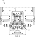
- the pair of floor-side charging contacts 212 may be sized and positioned such that the inner contact spacing S1 is larger than the drive wheel track width W. Similarly, the pair of floor-side charging contacts 212 may be sized and positioned such that the outer contact spacing S2 is smaller than the load wheel gap G. The sizing of the outer contact spacing S2 being smaller than the load wheel gap G permits passage of the steerable drive wheel 180 between the pair of floor-side charging contacts 212, along with passage of the pair of load wheels 190 outside of the pair of floor-side charging contacts 212, with vehicle movement along the central drive line 170.
- the pair of floor-side data transfer contacts 226 are carried by the multi-directional charging plate 260, and may be positioned between the floor-side charging contacts 212.
- the pair of floor-side data transfer contacts 226 are configured to transfer data to and from the materials handling vehicle 100.
- the floor-side data transfer contacts 226 are configured to contact the vehicle-side data transfer contacts 188.
- the vehicle-side data transfer contacts 188 and the floor-side data transfer contacts 226 define complementary contact profiles to facilitate data transfer between the charging station 200 and the materials handling vehicle 100 when the vehicle-side data transfer contacts 188 are in contact with the floor-side data transfer contacts 226.
- the vehicle-side data transfer contacts 188 transfer data from the materials handling vehicle 100 to the pair of floor-side data transfer contacts 226.
- the data transferred by the transfer contacts 226 may include battery data, vehicle data, charging station data, or any combination thereof. While the data transfer contacts 226 may be used to transfer data between the charging station 200 and the materials handling vehicle 100, data may be transferred alternatively or in addition to the data transfer contacts through the vehicle control system 112.
- the floor-mounted charging plate assembly 210 may include a multi-directional charging plate 260, and a mounting platform 240 configured to receive the charging plate 260.
- the mounting platform 240 may be configured as a can such that the charging plate 260 is received in the mounting platform 240 to form a lid portion of the mounting platform can.
- the charging plate 260 may be mounted to the mounting platform 240.
- the multi-directional charging plate 260 carries the floor-side charging contacts 212 and includes a charging plate footprint 262 that is rotationally symmetric at a plurality of mounting positions about a rotational mounting axis 244 orthogonal to a mounting plane defined by a rim 247 of the mounting platform 240.
- the charging plate footprint 262 may be rotationally symmetric through at least four rotational mounting positions.
- the multi-directional charging plate 260 may be rectangular or circular with appropriately positioned mounting holes 242 to allow the charging plate 260 to be oriented at different positions.
- the multi-directional charging plate 260 may have any shape, such as triangular, pentagonal, hexagonal, heptagonal, or the like.
- the charging plate 260 may have a number of positions equal to the number of sides of the charging plate 260.
- the floor-mounted charging plate assembly 210 may include mounting hardware 216.
- the mounting hardware 216 is configured to couple the charging plate 260 to the mounting platform 240.
- the mounting hardware 216 may be a fastener, such as bolt and nut, rivet, screw, or the like.
- the mounting platform 240 may be coupled to the charging plate 260 via welding, epoxy, adhesive, or the like.
- the mounting platform 240 may include a plurality of mounting holes 248 complementary to the mounting holes 242 in the charging plate 260.
- the plurality of mounting holes 248 and mounting holes 242 may be arranged such that the mounting hardware 216 may be inserted through mounting holes 248 and mounting holes 242.
- the mounting hardware 216 may be used to secure the multi-directional charging plate 260 to the mounting platform 240 through the complementary mounting holes 248 and mounting holes 242 at a plurality of mounting positions about the rotational mounting axis 244. In this manner, the multi-directional charging plate 260 may be mounted to the mounting platform 240 at a plurality of different rotational positions.
- the number of rotational positions may be equivalent to the number of mounting holes 242.
- the charging plate 260 can be rotationally oriented to ensure proper alignment of the vehicle-side charging contacts 144 of the vehicle-side charging contact assembly 140 with the floor-side charging contacts 212 of the charging station 200.
- This is particularly desirable in applications where the electrical polarity of the vehicle-side charging contacts 144 of the vehicle-side charging contact assembly 140 must match the electrical polarity of the floor-side charging contacts 212 for proper charging.
- the aforementioned mounting arrangement also allows the installer to orient the inner contact spacing S1 so that the drive wheel 180 of an approaching materials handling vehicle 100 may conveniently pass between the floor-side charging contacts 212.
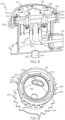
- the mounting platform 240 may include an upstanding receiving portion 280, a drain pipe 282 opposite the upstanding receiving portion 280, a plurality of peripherally-extending stabilizers 284 extending from a periphery of the mounting platform 240, and a bore 286 extending through the mounting platform 240 in a direction radially outward from the rotational mounting axis 244.
- the mounting platform 240 is configured to receive the charging plate 260 with the charging plate 260 coplanar with a terminal edge 281 of the upstanding receiving portion 280 of the mounting platform 240.
- the mounting platform 240 is configured to receive the charging plate 260 such that the charging plate 260 may be mounted to the mounting platform 240 so as to be coplanar with a travel surface of a warehouse floor 300, shown in FIGS. 9-11 .
- the mounting platform 240 is configured to be coupled to the warehouse floor 300, with the terminal edge 281 of the upstanding receiving portion 280 being coplanar with the warehouse floor 300.
- the bore 286 is configured to receive the floor-side charging circuitry 230 therethrough to connect from the battery charger 220 to the floor-side charging contacts 212, shown schematically in FIG. 1 .
- the drain pipe 282 may extend from the mounting platform 240 parallel to the rotational mounting axis 244.
- the drain pipe 282 may be in fluid communication with an interior of the mounting platform 240 such that fluid that enters into the mounting platform 240 through either the bore 286 or the upstanding receiving portion 280 may exit the mounting platform 240 through the drain pipe 282.
- the plurality of stabilizers 284 may be presented in a variety of forms.
- the stabilizers 284 may be presented in the form of flanged scallops, as is illustrated in FIGS. 5 and 6 , or in the form of angled rods, as is illustrated in FIGS. 7 and 8 .
- the plurality of stabilizers 284 extend radially outward from the rotational mounting axis 244 and may be circular, including rounded surfaces.
- the plurality of stabilizers 284 include a rod extending obliquely from the mounting platform 240, and a head coupled to the rod opposite the mounting platform 240.
- the head may be circular in shape. However, in embodiments, the head may include any shape.
- the stabilizers should be designed to enhance the degree to which the mounting platform 240, and the rest of the floor-mounted charging plate assembly 210, can be embedded in a warehouse floor with the use of concrete, or other similar materials.
- the plurality of stabilizers 284 may increase the surface area which the mounting platform 240 contacts the material in which it is embedded. The increased surface area increases the stability of the mounting platform 240 within the embedded material. In other words, the plurality of stabilizers 284 grip the material in which it is embedded to stabilize the mounting platform 240 when exposed to external forces, such as a force from a vehicle positioned on the charging plate 260.
- the plurality of stabilizers 284 may include an indicating stabilizer 285 that is visually distinct from a remaining plurality of stabilizers 284, as shown in FIG. 6 .
- the visually distinct stabilizer 285 may be triangular, including a front edge 287.
- the front edge 287 is configured to indicate a direction in which the mounting platform 240 is oriented during installation.
- a pair of visually distinct stabilizers 285 are provided on opposite sides of the mounting platform 240. These visually distinct stabilizers 285 can be used to orient the plurality of mounting holes 242 in the mounting platform 240 properly, to help ensure that the charging plate 260 can be oriented properly when it is secured to the mounting platform 240.
- the charging station 200 may include a conduit 241 extending from the mounting platform 240, and charging conductors 236 extending from the floor-side charging contacts 212, through the mounting platform 240 and the conduit 241, to the floor-side charging circuitry 230 of the charging station 200.
- the charging conductors 236 may be coupled to the floor-side charging contacts 212 to provide electrical current to the floor-side charging contacts 212.
- the charging conductors 236 may be coupled to the floor-side charging contacts 212 such that one of the floor-side charging contacts 212 may be a positive charging contact and the other of the floor-side charging contacts 212 may be a negative charging contact.
- the charging conductors 236 may be coupled to the battery charger 220 at an end opposite the floor-side charging contacts 212 such that electrical current may pass from the battery charger 220 through the charging conductors 236, and the charging conductors 236 may transfer electrical current from the battery charger 220 to the floor-side charging contacts 212.
- the charging conductors 236 may additionally transfer data from the data transfer contacts 226 to the battery charger 220.
- the battery charger 220 may be communicatively coupled to the master vehicle controller 114 such that the battery charger 220 may transfer the data from the data transfer contacts 226 to the master vehicle controller 114.
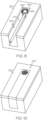
- a trench 302 may be formed in a warehouse floor 300 by removing part of the warehouse floor 300.
- the warehouse floor 300 may be made of, for example, concrete.
- the mounting platform 240 and conduit 241 may then positioned within the trench 302.
- the mounting platform 240 may be positioned at an end 304 of the trench 302 with the drain pipe 282 extending downward from the mounting platform 240 away from the warehouse floor 300.
- the mounting platform 240 may be oriented using the visually distinct stabilizer 285 to position the mounting platform 240 relative to, for example, a path of travel of the materials handling vehicle 100.
- the conduit 241 may be positioned such that the conduit 241 extends along the trench 302 from the mounting platform 240.
- the charging conductors 236 of the floor-side charging circuitry 230 may be routed through the conduit 241 to extend into the mounting platform 240.
- the trench 302 may be filled with filler material, such as, for example, gravel to extend around the mounting platform 240 and the conduit 241.
- the filler material allows for drainage of fluids that may flow around or through the mounting platform 240.
- the drain pipe 282 may extend into the filler material to direct fluid out of the mounting platform 240 and away from the conduit 241.
- the warehouse floor 300 may then be replaced on top of the filler material.
- the charging conductors 236 extending into the mounting platform 240 may be coupled to the floor-side charging contacts 212.
- the charging plate 260 may then be coupled to the mounting platform 240.
- the charging plate 260 may be oriented relative to the mounting platform 240 in one of the plurality of rotational positions by aligning the mounting holes 242 on the charging plate 260 with the mounting holes 248 on the mounting platform 240.
- the charging plate 260 may then be fixed to the mounting platform 240 via the mounting hardware 216.
- a "warehouse” encompasses any indoor or outdoor industrial facility in which materials handling vehicles transport goods including, but not limited to, indoor or outdoor industrial facilities that are intended primarily for the storage of goods, such as those where multilevel racks are arranged in aisles, and manufacturing facilities where goods are transported about the facility by materials handling vehicles for use in one or more manufacturing processes.
- references herein of a component of the present disclosure being "configured” in a particular way, to embody a particular property, or to function in a particular manner, are structural recitations, as opposed to recitations of intended use. More specifically, the references herein to the manner in which a component is “configured” denotes an existing physical condition of the component and, as such, is to be taken as a definite recitation of the structural characteristics of the component.
Landscapes
- Engineering & Computer Science (AREA)
- Transportation (AREA)
- Mechanical Engineering (AREA)
- Power Engineering (AREA)
- Structural Engineering (AREA)
- Civil Engineering (AREA)
- Life Sciences & Earth Sciences (AREA)
- Geology (AREA)
- Computer Networks & Wireless Communication (AREA)
- Charge And Discharge Circuits For Batteries Or The Like (AREA)
- Electric Propulsion And Braking For Vehicles (AREA)
- Secondary Cells (AREA)
Claims (15)
- Ladesystem für ein Materialhandhabungsfahrzeug, das ein Materialhandhabungsfahrzeug (100) und eine Ladestation (200) umfasst, wobei:das Materialhandhabungsfahrzeug (100) Folgendes umfasst: einen Materialhandhabungsmechanismus (110), eine Batterie (120), einen von der Batterie (120) gespeisten Antriebsmechanismus (130), eine zentrale Antriebslinie (170), die sich zwischen einem vorderen Ende (172) und einem hinteren Ende (174) des Materialhandhabungsfahrzeugs (100) erstreckt, ein lenkbares Antriebsrad (180), das mit dem Antriebsmechanismus (130) motorisch gekoppelt ist, und ein Paar Lasträder (190), die auf gegenüberliegenden Seiten der zentralen Antriebslinie (170) angeordnet sind;das lenkbare Antriebsrad (180) mit der zentralen Antriebslinie (170) ausgerichtet ist und eine Antriebsradspurbreite W definiert;das Paar Lasträder (190) auf gegenüberliegenden Seiten der zentralen Antriebslinie (170) positioniert ist und einen Lastradspalt G zwischen dem Paar Lasträdern (190) definiert, der größer ist als die Antriebsradspurbreite W;dadurch gekennzeichnet, dass das Materialhandhabungsfahrzeug ferner eine fahrzeugseitige Ladekontaktanordnung (140) umfasst, die ein fahrzeugseitiges Kontaktprofil (150) definiert, wobei eine fahrzeugseitige Ladeschaltung (160) die fahrzeugseitige Ladekontaktanordnung (140) mit der Batterie (120) koppelt; und wobeidie Ladestation (200) eine bodenmontierte Ladeplattenanordnung (210), ein Batterieladegerät (220) und eine bodenseitige Ladeschaltung (230) umfasst, die die bodenmontierte Ladeplattenanordnung (210) mit dem Batterieladegerät (220) koppelt;die bodenmontierte Ladeplattenanordnung (210) ein Paar bodenseitige Ladekontakte (212) umfasst, die ein bodenseitiges Kontaktprofil (214) definieren, das das fahrzeugseitige Kontaktprofil (150) der fahrzeugseitigen Ladekontaktanordnung (140) ergänzt, um eine direkte Kontaktübertragung von Ladestrom von den bodenseitigen Ladekontakten (212) zur fahrzeugseitigen Ladekontaktanordnung (140) zu ermöglichen; unddas Paar bodenseitige Ladekontakte (212) einen inneren Kontaktabstand S1, der größer als die Antriebsradspurbreite W ist, und einen äußeren Kontaktabstand S2, der größer als der innere Kontaktabstand S1 und kleiner als der Lastradspalt G ist, definiert, um den Durchgang des lenkbaren Antriebsrades (180) zwischen dem Paar bodenseitigen Ladekontakten (212) zu ermöglichen, gefolgt vom Durchgang des Paares von Lasträdern (190) außerhalb des Paares von bodenseitigen Ladekontakten (212), mit einer Fahrzeugbewegung entlang der zentralen Antriebslinie (170).
- Ladesystem für Materialhandhabungsfahrzeuge nach Anspruch 1, wobei:die bodenmontierte Ladeplattenanordnung (210) eine Montageplattform (240) und eine an der Montageplattform (240) montierte multidirektionale Ladeplatte (260) umfasst; unddie multidirektionale Ladeplatte (260) die bodenseitigen Ladekontakte (212) trägt und eine Ladeplattengrundfläche (262) aufweist, die durch mindestens vier Drehmontagepositionen um eine Drehmontageachse (244) orthogonal zu einer durch die Montageplattform (240) definierten Montageebene drehsymmetrisch ist.
- Ladesystem für Materialhandhabungsfahrzeuge nach Anspruch 1, wobei:die bodenmontierte Ladeplattenanordnung (210) eine Montageplattform (240) und eine an der Montageplattform (240) montierte multidirektionale Ladeplatte (260) umfasst;die bodenseitigen Ladekontakte (212) von der multidirektionalen Ladeplatte (260) getragen werden und einen positiven bodenseitigen Kontakt (217) und einen davon beabstandeten negativen bodenseitigen Kontakt (218) aufweisen, um den inneren Kontaktabstand S1 zu definieren; unddie multidirektionale Ladeplatte (260) einen in einer primären Kardinalrichtung orientierten Richtungsanzeiger (270) aufweist und der positive bodenseitige Kontakt (217) und der negative bodenseitige Kontakt (218) auf gegenüberliegenden Seiten einer Bewegungslinie liegen, die sich in der primären Kardinalrichtung zwischen dem positiven bodenseitigen Kontakt (217) und dem negativen bodenseitigen Kontakt (218) erstreckt.
- Ladesystem für Materialhandhabungsfahrzeuge nach Anspruch 3, wobei die multidirektionale Ladeplatte (260) ein Paar Richtungsanzeiger (270) umfasst, von denen sich einer auf einer Eingangsseite (221) eines Raums zwischen den bodenseitigen Ladekontakten (212) und der andere auf einer Ausgangsseite (223) des Raums zwischen den bodenseitigen Ladekontakten (212) befindet.
- Ladesystem für Materialhandhabungsfahrzeuge nach Anspruch 1, wobei:der innere Kontaktabstand S1 etwa 50 mm bis etwa 400 mm beträgt;der äußere Kontaktabstand S2 etwa 120 mm bis etwa 500 mm beträgt;die Antriebsradspurbreite W etwa 40 mm bis etwa 160 mm beträgt; undder Lastradabstand G etwa 300 cm bis etwa 1600 cm beträgt.
- Ladesystem für Materialhandhabungsfahrzeuge nach Anspruch 1, wobei:die Antriebsradspurbreite W mindestens etwa 40 mm beträgt;der innere Kontaktabstand S1 mindestens etwa 15 mm größer als die Antriebsradspurbreite W ist;der äußere Kontaktabstand S2 mindestens etwa 70 mm größer als der innere Kontaktabstand S1 ist; undder Lastradspalt G mindestens etwa 20 mm größer als der äußere Kontaktabstand S2 ist.
- Ladesystem für Materialhandhabungsfahrzeuge nach Anspruch 1, wobei die bodenmontierte Ladeplattenanordnung (210) eine Montageplattform (240) umfasst, die zum Aufnehmen einer Ladeplatte (260) konfiguriert ist,die Montageplattform (240) als Dose konfiguriert ist und die Ladeplatte (260) einen Deckelabschnitt der Dose der Montageplattform (240) bildet; unddie Ladestation (200) eine sich von der Dose der Montageplattform (240) erstreckende Leitung (241) und sich von den bodenseitigen Ladekontakten (212) durch die Dose der Montageplattform (240) und die Leitung (241) zu bodenseitigen Ladeschaltungen (230) der Ladestation (200) erstreckende Ladeleiter (236) umfasst.
- Ladesystem für Materialhandhabungsfahrzeuge nach Anspruch 1, wobei:die bodenmontierte Ladeplattenanordnung (210) eine Montageplattform (240) umfasst, die zur Aufnahme einer Ladeplatte (260) konfiguriert ist;die Montageplattform (240) einen aufrechten Aufnahmeabschnitt (280) umfasst; unddie Montageplattform (240) zum Aufnehmen der Ladeplatte (260) konfiguriert ist, wobei die Ladeplatte (260) koplanar mit einer Abschlusskante (281) des aufrechten Aufnahmeabschnitts (280) der Montageplattform (240) ist.
- Ladesystem für Materialhandhabungsfahrzeuge nach Anspruch 1, wobei:die bodenmontierte Ladeplattenanordnung (210) eine Montageplattform (240) umfasst, die zur Aufnahme einer Ladeplatte (260) konfiguriert ist; unddie Montageplattform (240) zum Aufnehmen der Ladeplatte (260) konfiguriert ist, so dass die Ladeplatte (260) an der Montageplattform (240) so montiert werden kann, dass sie koplanar mit einer Fahrfläche eines Lagerhausbodens (300) ist.
- Ladesystem für Materialhandhabungsfahrzeuge nach Anspruch 1, wobei:die bodenmontierte Ladeplattenanordnung (210) eine Montageplattform (240) umfasst, die zur Aufnahme einer Ladeplatte (260) konfiguriert ist; unddie Montageplattform mehrere sich in Umfangsrichtung erstreckende Stabilisatoren umfasst.
- Ladesystem für Materialhandhabungsfahrzeuge nach Anspruch 10, wobei:die bodenmontierte Ladeplattenanordnung (210) Montage-Hardware (216) umfasst;die Montageplattform (240) und die Ladeplatte (260) mehrere komplementäre Montagelöcher (248) aufweisen, die so angeordnet sind, dass die Montage-Hardware (216) zum Befestigen der Ladeplatte (260) durch die komplementären Montagelöcher (248) an der Montageplattform (240) verwendet werden kann; unddie sich in Umfangsrichtung erstreckenden Stabilisatoren (284) einen Stabilisator (285) umfassen, der sich visuell von einer verbleibenden Mehrzahl der Stabilisatoren (284) unterscheidet.
- Ladesystem für Materialhandhabungsfahrzeuge nach Anspruch 1, wobei:das lenkbare Antriebsrad (180) am vorderen Ende (172) des Materialhandhabungsfahrzeugs (100) angeordnet ist;das Paar Lasträder (190) am hinteren Ende (174) des Materialhandhabungsfahrzeugs (100) angeordnet ist;die fahrzeugseitige Ladekontaktanordnung (140) am hinteren Ende (174) des Materialhandhabungsfahrzeugs (100) angeordnet ist; unddas Materialhandhabungsfahrzeug (100) ein Schlepper ist, der zum Ziehen einer Last vom hinteren Ende (174) des Materialhandhabungsfahrzeugs (100) konfiguriert ist.
- Ladesystem für Materialhandhabungsfahrzeuge nach Anspruch 1, wobei die fahrzeugseitige Ladekontaktanordnung (140) am hinteren Ende (174) des Materialhandhabungsfahrzeugs (100) positioniert ist und einen fahrzeugseitigen Aktuator (142) umfasst, der zum Absenken der fahrzeugseitigen Ladekontakte (144) in Kontakt mit dem Paar bodenseitigen Ladekontakten (212) der bodenmontierten Ladeplattenanordnung (210) konfiguriert ist.
- Ladesystem für Materialhandhabungsfahrzeuge nach Anspruch 1, wobei:das Materialhandhabungsfahrzeug (100) ferner fahrzeugseitige Datenübertragungskontakte (188) und fahrzeugseitige Datenübertragungsschaltungen (192) umfasst;die bodenmontierte Ladeplattenanordnung (210) ferner bodenseitige Datenübertragungskontakte (226) umfasst, die zwischen den bodenseitigen Ladekontakten (212) angeordnet sind; unddie fahrzeugseitigen Datenübertragungskontakte (188) und die bodenseitige Datenübertragungskontakte (226) komplementäre Kontaktprofile definieren, um Datenübertragung zwischen der Ladestation (200) und dem Materialhandhabungsfahrzeug (100) zu erleichtern.
- Ladesystem für Materialhandhabungsfahrzeuge nach Anspruch 1, wobei:die bodenmontierte Ladeplattenbaugruppe (210) ein Paar bodenseitige Ladekontakte (212) umfasst, die ein bodenseitiges Kontaktprofil (214) definieren, das zum Ergänzen eines fahrzeugseitigen Kontaktprofils (150) eines Ziel-Materialhandhabungsfahrzeugs (100) konfiguriert ist, um eine direkte Kontaktübertragung von Ladestrom von den bodenseitigen Ladekontakten (212) zu einer fahrzeugseitigen Ladekontaktbaugruppe (140) zu ermöglichen; unddas Paar bodenseitige Ladekontakte (212) einen inneren Kontaktabstand S1, der größer ist als eine Antriebsradspurbreite W des Ziel-Materialhandhabungsfahrzeugs (100), und einen äußeren Kontaktabstand S2 definiert, der größer als der innere Kontaktabstand S1 und kleiner als ein Lastradspalt G des Ziel-Materialhandhabungsfahrzeugs (100) ist, um den Durchgang eines lenkbaren Antriebsrades (180) des Ziel-Materialhandhabungsfahrzeugs (100) zwischen dem Paar bodenseitigen Ladekontakten (212) zu ermöglichen, gefolgt vom Durchgang eines Paares von Lasträdern (190) des Ziel-Materialhandhabungsfahrzeugs (100) außerhalb des Paares bodenseitiger Ladekontakte (212).
Priority Applications (1)
| Application Number | Priority Date | Filing Date | Title |
|---|---|---|---|
| EP23218332.7A EP4316901A3 (de) | 2020-07-02 | 2021-07-01 | Ladesystem für materialhandhabungsfahrzeug mit einer bodenmontierten ladeplatte |
Applications Claiming Priority (2)
| Application Number | Priority Date | Filing Date | Title |
|---|---|---|---|
| US202063047445P | 2020-07-02 | 2020-07-02 | |
| PCT/US2021/040092 WO2022006398A1 (en) | 2020-07-02 | 2021-07-01 | Materials handling vehicle charging system comprising a floor-mounted charging plate |
Related Child Applications (2)
| Application Number | Title | Priority Date | Filing Date |
|---|---|---|---|
| EP23218332.7A Division-Into EP4316901A3 (de) | 2020-07-02 | 2021-07-01 | Ladesystem für materialhandhabungsfahrzeug mit einer bodenmontierten ladeplatte |
| EP23218332.7A Division EP4316901A3 (de) | 2020-07-02 | 2021-07-01 | Ladesystem für materialhandhabungsfahrzeug mit einer bodenmontierten ladeplatte |
Publications (2)
| Publication Number | Publication Date |
|---|---|
| EP4175847A1 EP4175847A1 (de) | 2023-05-10 |
| EP4175847B1 true EP4175847B1 (de) | 2024-04-24 |
Family
ID=77051203
Family Applications (2)
| Application Number | Title | Priority Date | Filing Date |
|---|---|---|---|
| EP21746284.5A Active EP4175847B1 (de) | 2020-07-02 | 2021-07-01 | Ladesystem für materialhandhabungsfahrzeug mit einer bodenmontierten ladeplatte |
| EP23218332.7A Pending EP4316901A3 (de) | 2020-07-02 | 2021-07-01 | Ladesystem für materialhandhabungsfahrzeug mit einer bodenmontierten ladeplatte |
Family Applications After (1)
| Application Number | Title | Priority Date | Filing Date |
|---|---|---|---|
| EP23218332.7A Pending EP4316901A3 (de) | 2020-07-02 | 2021-07-01 | Ladesystem für materialhandhabungsfahrzeug mit einer bodenmontierten ladeplatte |
Country Status (8)
| Country | Link |
|---|---|
| US (2) | US11897350B2 (de) |
| EP (2) | EP4175847B1 (de) |
| KR (1) | KR102913504B1 (de) |
| CN (1) | CN115835976B (de) |
| AU (2) | AU2021299554B2 (de) |
| CA (1) | CA3188514A1 (de) |
| MX (1) | MX2022016563A (de) |
| WO (1) | WO2022006398A1 (de) |
Families Citing this family (1)
| Publication number | Priority date | Publication date | Assignee | Title |
|---|---|---|---|---|
| DE102023128127A1 (de) | 2023-10-13 | 2025-04-17 | Fronius International Gmbh | System und Verfahren zum Laden einer mobilen Einheit |
Family Cites Families (56)
| Publication number | Priority date | Publication date | Assignee | Title |
|---|---|---|---|---|
| CN1261319C (zh) * | 2004-11-11 | 2006-06-28 | 北京电巴科技有限公司 | 一种电动公交系统 |
| JP4305780B2 (ja) | 2007-07-31 | 2009-07-29 | 日本輸送機株式会社 | 走行制御装置及び該装置を備えた走行車両及びフォークリフト、並びに走行制御方法 |
| US7825335B2 (en) | 2008-02-29 | 2010-11-02 | Hubbell Incorporated | Metallic floor box with non-metalic riser and flange |
| RU2506181C2 (ru) | 2009-07-15 | 2014-02-10 | Кондуктикс-Вампфлер Гмбх | Система для индуктивной зарядки транспортных средств, снабженных электронной системой позиционирования |
| US8447448B2 (en) * | 2009-11-05 | 2013-05-21 | GM Global Technology Operations LLC | Automated guided vehicle |
| US8853999B2 (en) | 2010-04-19 | 2014-10-07 | Interim Designs Inc. | Automated electric vehicle charging system and method |
| US9496732B2 (en) * | 2011-01-18 | 2016-11-15 | Mojo Mobility, Inc. | Systems and methods for wireless power transfer |
| US9178369B2 (en) | 2011-01-18 | 2015-11-03 | Mojo Mobility, Inc. | Systems and methods for providing positioning freedom, and support of different voltages, protocols, and power levels in a wireless power system |
| DE102012007713B4 (de) * | 2011-04-20 | 2015-03-19 | SALT AND PEPPER Holding GmbH & Co. KG | Vorrichtung zum elektrischen Laden von elektrisch angetriebenen Straßenfahrzeugen |
| US8471522B2 (en) | 2011-05-06 | 2013-06-25 | Toyota Motor Engineering & Manufacturing North America, Inc. | System for charging electrically powered automated guided vehicles |
| US9722447B2 (en) * | 2012-03-21 | 2017-08-01 | Mojo Mobility, Inc. | System and method for charging or powering devices, such as robots, electric vehicles, or other mobile devices or equipment |
| US9718367B2 (en) | 2012-08-30 | 2017-08-01 | Proterra Inc. | Side-facing vehicle charging system |
| CN203438872U (zh) | 2013-06-26 | 2014-02-19 | 广州市远能物流自动化设备科技有限公司 | 无人搬运车在线充电结构 |
| US9170581B2 (en) | 2013-09-30 | 2015-10-27 | Crown Equipment Limited | Industrial vehicles with overhead light based localization |
| US20150091507A1 (en) * | 2013-09-30 | 2015-04-02 | Elwha Llc | Dwelling related information center associated with communication and control system and method for wireless electric vehicle electrical energy transfer |
| DE102015207992A1 (de) * | 2014-05-02 | 2015-11-05 | Ford Global Technologies, Llc | Fahrzeugbatterieladesystem und -verfahren |
| KR101583054B1 (ko) | 2014-07-03 | 2016-01-21 | 주식회사코어벨 | 무인운반차 자동충전시스템 |
| US20160013510A1 (en) * | 2014-07-09 | 2016-01-14 | Denso International America, Inc. | Bubble battery system |
| US9174830B1 (en) | 2014-09-29 | 2015-11-03 | Crown Equipment Limited | Industrial vehicles with point fix based localization |
| US9869105B2 (en) * | 2015-07-07 | 2018-01-16 | Ford Global Technologies Llc | Alignment structure for a wireless charging station |
| US9884751B2 (en) | 2015-09-17 | 2018-02-06 | Gray Manufacturing Company, Inc. | Battery operated vehicle lifts with wireless charging |
| US20170140349A1 (en) * | 2015-11-13 | 2017-05-18 | NextEv USA, Inc. | Vehicle Group Charging System and Method of Use |
| US10093195B2 (en) * | 2015-11-13 | 2018-10-09 | Nio Usa, Inc. | Integrated vehicle charging panel system and method of use |
| CN105621255B8 (zh) | 2016-03-04 | 2017-06-06 | 无锡市百宏传动电器有限公司 | 自动搬运车充电装置 |
| US11230309B2 (en) * | 2016-05-12 | 2022-01-25 | Transtech of South Carolina, INC | Charging system for electric vehicles |
| JP6657533B2 (ja) | 2016-05-12 | 2020-03-04 | 株式会社ダイヘン | 無人搬送車システム |
| US10303171B1 (en) | 2016-09-29 | 2019-05-28 | Amazon Technologies, Inc. | Autonomous ground vehicles providing ordered items in pickup areas |
| DE102016120693A1 (de) * | 2016-10-28 | 2018-05-03 | Still Gmbh | Flurförderzeug mit einem eine Traktionsbatterie aufweisenden batterie-elektrischen Antriebssystem |
| DE102016121229A1 (de) | 2016-11-07 | 2018-05-09 | Paul Vahle Gmbh & Co. Kg | Kontaktlose Detektion von Batterie-Ladekontakten |
| DE102016121355B4 (de) | 2016-11-08 | 2024-02-22 | Easelink Gmbh | Fahrzeugverbindungsvorrichtung sowie Fahrzeugverbindungssystem |
| CN106602660B (zh) | 2016-12-30 | 2019-12-06 | 西安航天精密机电研究所 | 一种agv的自动充电装置 |
| CN108363389A (zh) | 2017-01-16 | 2018-08-03 | 浙江国自机器人技术有限公司 | 一种应用于移动机器人的超声波避障系统 |
| CN206481085U (zh) | 2017-02-24 | 2017-09-08 | 智久(厦门)机器人科技有限公司 | Agv自动充电系统 |
| CN206589714U (zh) | 2017-02-24 | 2017-10-27 | 智久(厦门)机器人科技有限公司 | 一种agv自动充电装置 |
| DE102017218226A1 (de) * | 2017-03-20 | 2018-09-20 | Fraunhofer-Gesellschaft zur Förderung der angewandten Forschung e.V. | Unterflur-Kontaktsystem |
| US10383499B2 (en) * | 2017-08-31 | 2019-08-20 | Irobot Corporation | Wet robot docking station |
| CN107738592A (zh) | 2017-11-07 | 2018-02-27 | 河南森源电气股份有限公司 | Agv用充电装置及agv |
| CN108081980A (zh) | 2017-11-21 | 2018-05-29 | 武汉中元华电科技股份有限公司 | 一种机器人的自主充电安全控制系统及控制方法 |
| CN108116266A (zh) | 2017-12-31 | 2018-06-05 | 芜湖哈特机器人产业技术研究院有限公司 | 一种agv自动充电装置及其使用方法 |
| JP7075776B2 (ja) | 2018-02-21 | 2022-05-26 | 国立大学法人豊橋技術科学大学 | 無人搬送装置 |
| CN111971872A (zh) * | 2018-03-28 | 2020-11-20 | 松下知识产权经营株式会社 | 电极组件、送电装置、受电装置以及无线电力传输系统 |
| EP3552860A1 (de) * | 2018-04-10 | 2019-10-16 | Hager-Electro Sas | Ladestecker und ladeempfänger |
| CN108556674A (zh) | 2018-05-29 | 2018-09-21 | 河南森源电气股份有限公司 | 一种agv车充电装置 |
| TWI660557B (zh) | 2018-06-01 | 2019-05-21 | 和碩聯合科技股份有限公司 | 充電座 |
| CN108909512A (zh) * | 2018-07-26 | 2018-11-30 | 张勤 | 一种环形升降智能化自动对接新能源汽车充电系统 |
| US10566734B1 (en) | 2018-08-02 | 2020-02-18 | Roboteq, Inc | System for facilitating electrical connection of a first electrical unit comprised in a first object with a second electrical unit comprised in a second object |
| CN208664983U (zh) | 2018-08-10 | 2019-03-29 | 机械工业第六设计研究院有限公司 | 用于agv小车的地面充电装置 |
| US10921819B2 (en) * | 2018-08-28 | 2021-02-16 | Asi Technologies, Inc. | Automated guided vehicle system and automated guided vehicle for use therein |
| CA3117719C (en) * | 2018-10-25 | 2022-01-18 | Gestion Inogec Inc. | Omniwheel track system and platform using the same |
| CN109572460B (zh) | 2019-01-11 | 2024-04-05 | 龙合智能装备制造有限公司 | 轮式机器人自动充电方法及装置 |
| CN110253476A (zh) | 2019-07-08 | 2019-09-20 | 大庆科瑞电子技术开发有限公司 | 一种基于油田计量站的无人值守阀组控制装置 |
| US11691529B2 (en) * | 2019-09-23 | 2023-07-04 | Abb Schweiz Ag | Systems and methods for automated electrical connector positioning for electric vehicle charging |
| US20210114471A1 (en) * | 2019-10-22 | 2021-04-22 | Byton North America Corporation | Battery charging using vehicle underbody shield |
| US10940873B1 (en) * | 2020-06-22 | 2021-03-09 | Monique Irena Summers | Modified passenger, suitable or newly manufactured railroad cars provide electrical charging for battery-powered electric automobiles while in transit |
| US12024036B2 (en) * | 2021-02-15 | 2024-07-02 | Scott Paterson | Electric vehicle automatic charging station |
| US12024039B2 (en) * | 2021-12-07 | 2024-07-02 | Arnold Chase | Vehicle self-centered charging system |
-
2021
- 2021-06-30 US US17/363,953 patent/US11897350B2/en active Active
- 2021-07-01 CA CA3188514A patent/CA3188514A1/en active Pending
- 2021-07-01 KR KR1020237003768A patent/KR102913504B1/ko active Active
- 2021-07-01 WO PCT/US2021/040092 patent/WO2022006398A1/en not_active Ceased
- 2021-07-01 EP EP21746284.5A patent/EP4175847B1/de active Active
- 2021-07-01 CN CN202180047028.9A patent/CN115835976B/zh active Active
- 2021-07-01 MX MX2022016563A patent/MX2022016563A/es unknown
- 2021-07-01 EP EP23218332.7A patent/EP4316901A3/de active Pending
- 2021-07-01 AU AU2021299554A patent/AU2021299554B2/en active Active
-
2023
- 2023-11-14 US US18/508,740 patent/US12083909B2/en active Active
-
2025
- 2025-08-05 AU AU2025213571A patent/AU2025213571A1/en active Pending
Also Published As
| Publication number | Publication date |
|---|---|
| KR102913504B1 (ko) | 2026-01-19 |
| EP4175847A1 (de) | 2023-05-10 |
| CA3188514A1 (en) | 2022-01-06 |
| CN115835976B (zh) | 2026-01-06 |
| AU2021299554A1 (en) | 2023-02-23 |
| EP4316901A3 (de) | 2024-04-24 |
| AU2021299554A2 (en) | 2023-03-23 |
| US11897350B2 (en) | 2024-02-13 |
| KR20230035075A (ko) | 2023-03-10 |
| AU2021299554B2 (en) | 2025-09-11 |
| EP4316901A2 (de) | 2024-02-07 |
| US20220001758A1 (en) | 2022-01-06 |
| US20240083272A1 (en) | 2024-03-14 |
| WO2022006398A1 (en) | 2022-01-06 |
| CN115835976A (zh) | 2023-03-21 |
| AU2025213571A1 (en) | 2025-08-21 |
| US12083909B2 (en) | 2024-09-10 |
| MX2022016563A (es) | 2023-06-07 |
Similar Documents
| Publication | Publication Date | Title |
|---|---|---|
| CN105888338B (zh) | 一种基于uwb定位的智能汽车搬运机器人及其控制方法 | |
| CN206128772U (zh) | 一种基于uwb定位的智能汽车搬运机器人 | |
| EP4177097A1 (de) | Ladesysteme und -verfahren für materialhandhabungsfahrzeug mit positionskompensation | |
| BR102021016854A2 (pt) | Veículo guiado automaticamente | |
| EP2974992A1 (de) | Reifen-reifen-portalkran und portalhubwagen zur aufnahme von energieeinspeisung in kontaktlosem modus | |
| CN205468997U (zh) | 一种防倾倒的旋转式agv物流车 | |
| KR101981989B1 (ko) | 무인운반차량 | |
| CN104149875A (zh) | 激光导航叉车型agv小车 | |
| US12083909B2 (en) | Materials handling vehicle charging system comprising a floor-mounted charging plate | |
| CN113493173A (zh) | 搬运装置 | |
| CN115196264B (zh) | 一种具有车载夹持器的协同搬运机器人及其控制方法 | |
| KR20180012434A (ko) | 작업자 위치추종식 자동운행 기반 전동형 물류지원차량 및 위치추종식 자동운행 기반 전동형 물류지원차량 시스템 | |
| CN109677819A (zh) | 自动引导运输车和货物搬运系统 | |
| CN217201921U (zh) | 自动叉车 | |
| CN218578824U (zh) | 自动引导运输车搬运装置 | |
| CN219174134U (zh) | 激光导航agv叉车 | |
| CN118458387A (zh) | 一种智能运输机器人及运输方法 | |
| CN117208490A (zh) | 一种平库机器人及其操作系统 | |
| CN107902605A (zh) | 一种高安全性的自动引导搬运车 | |
| CN222791130U (zh) | 螺栓装配装置 | |
| JP2007204203A (ja) | 走行制御装置及びこれを用いた移動体 | |
| EP3865355B1 (de) | Transportanordnung zum transport eines objekts auf einer oberfläche | |
| CN120504272A (zh) | 用于将自动导引车对接到物料搬运车的系统和方法 | |
| JP2024134449A (ja) | 搬送装置 | |
| HK40088021A (zh) | 具有位置补偿的物料搬运车辆充电系统和方法 |
Legal Events
| Date | Code | Title | Description |
|---|---|---|---|
| STAA | Information on the status of an ep patent application or granted ep patent |
Free format text: STATUS: UNKNOWN |
|
| STAA | Information on the status of an ep patent application or granted ep patent |
Free format text: STATUS: THE INTERNATIONAL PUBLICATION HAS BEEN MADE |
|
| PUAI | Public reference made under article 153(3) epc to a published international application that has entered the european phase |
Free format text: ORIGINAL CODE: 0009012 |
|
| STAA | Information on the status of an ep patent application or granted ep patent |
Free format text: STATUS: REQUEST FOR EXAMINATION WAS MADE |
|
| 17P | Request for examination filed |
Effective date: 20230124 |
|
| AK | Designated contracting states |
Kind code of ref document: A1 Designated state(s): AL AT BE BG CH CY CZ DE DK EE ES FI FR GB GR HR HU IE IS IT LI LT LU LV MC MK MT NL NO PL PT RO RS SE SI SK SM TR |
|
| P01 | Opt-out of the competence of the unified patent court (upc) registered |
Effective date: 20230529 |
|
| DAV | Request for validation of the european patent (deleted) | ||
| DAX | Request for extension of the european patent (deleted) | ||
| GRAP | Despatch of communication of intention to grant a patent |
Free format text: ORIGINAL CODE: EPIDOSNIGR1 |
|
| STAA | Information on the status of an ep patent application or granted ep patent |
Free format text: STATUS: GRANT OF PATENT IS INTENDED |
|
| RIC1 | Information provided on ipc code assigned before grant |
Ipc: B60L 53/16 20190101ALI20231206BHEP Ipc: H02J 7/00 20060101ALI20231206BHEP Ipc: B66F 9/075 20060101ALI20231206BHEP Ipc: B60L 53/30 20190101ALI20231206BHEP Ipc: B60L 50/00 20190101AFI20231206BHEP |
|
| INTG | Intention to grant announced |
Effective date: 20240109 |
|
| GRAS | Grant fee paid |
Free format text: ORIGINAL CODE: EPIDOSNIGR3 |
|
| GRAA | (expected) grant |
Free format text: ORIGINAL CODE: 0009210 |
|
| STAA | Information on the status of an ep patent application or granted ep patent |
Free format text: STATUS: THE PATENT HAS BEEN GRANTED |
|
| AK | Designated contracting states |
Kind code of ref document: B1 Designated state(s): AL AT BE BG CH CY CZ DE DK EE ES FI FR GB GR HR HU IE IS IT LI LT LU LV MC MK MT NL NO PL PT RO RS SE SI SK SM TR |
|
| REG | Reference to a national code |
Ref country code: GB Ref legal event code: FG4D |
|
| REG | Reference to a national code |
Ref country code: CH Ref legal event code: EP |
|
| REG | Reference to a national code |
Ref country code: DE Ref legal event code: R096 Ref document number: 602021012364 Country of ref document: DE |
|
| REG | Reference to a national code |
Ref country code: IE Ref legal event code: FG4D |
|
| REG | Reference to a national code |
Ref country code: LT Ref legal event code: MG9D |
|
| REG | Reference to a national code |
Ref country code: NL Ref legal event code: MP Effective date: 20240424 |
|
| REG | Reference to a national code |
Ref country code: AT Ref legal event code: MK05 Ref document number: 1679241 Country of ref document: AT Kind code of ref document: T Effective date: 20240424 |
|
| PG25 | Lapsed in a contracting state [announced via postgrant information from national office to epo] |
Ref country code: NL Free format text: LAPSE BECAUSE OF FAILURE TO SUBMIT A TRANSLATION OF THE DESCRIPTION OR TO PAY THE FEE WITHIN THE PRESCRIBED TIME-LIMIT Effective date: 20240424 |
|
| PG25 | Lapsed in a contracting state [announced via postgrant information from national office to epo] |
Ref country code: NL Free format text: LAPSE BECAUSE OF FAILURE TO SUBMIT A TRANSLATION OF THE DESCRIPTION OR TO PAY THE FEE WITHIN THE PRESCRIBED TIME-LIMIT Effective date: 20240424 |
|
| PG25 | Lapsed in a contracting state [announced via postgrant information from national office to epo] |
Ref country code: IS Free format text: LAPSE BECAUSE OF FAILURE TO SUBMIT A TRANSLATION OF THE DESCRIPTION OR TO PAY THE FEE WITHIN THE PRESCRIBED TIME-LIMIT Effective date: 20240824 |
|
| PG25 | Lapsed in a contracting state [announced via postgrant information from national office to epo] |
Ref country code: BG Free format text: LAPSE BECAUSE OF FAILURE TO SUBMIT A TRANSLATION OF THE DESCRIPTION OR TO PAY THE FEE WITHIN THE PRESCRIBED TIME-LIMIT Effective date: 20240424 |
|
| PG25 | Lapsed in a contracting state [announced via postgrant information from national office to epo] |
Ref country code: HR Free format text: LAPSE BECAUSE OF FAILURE TO SUBMIT A TRANSLATION OF THE DESCRIPTION OR TO PAY THE FEE WITHIN THE PRESCRIBED TIME-LIMIT Effective date: 20240424 Ref country code: FI Free format text: LAPSE BECAUSE OF FAILURE TO SUBMIT A TRANSLATION OF THE DESCRIPTION OR TO PAY THE FEE WITHIN THE PRESCRIBED TIME-LIMIT Effective date: 20240424 |
|
| PG25 | Lapsed in a contracting state [announced via postgrant information from national office to epo] |
Ref country code: GR Free format text: LAPSE BECAUSE OF FAILURE TO SUBMIT A TRANSLATION OF THE DESCRIPTION OR TO PAY THE FEE WITHIN THE PRESCRIBED TIME-LIMIT Effective date: 20240725 |
|
| PG25 | Lapsed in a contracting state [announced via postgrant information from national office to epo] |
Ref country code: PT Free format text: LAPSE BECAUSE OF FAILURE TO SUBMIT A TRANSLATION OF THE DESCRIPTION OR TO PAY THE FEE WITHIN THE PRESCRIBED TIME-LIMIT Effective date: 20240826 |
|
| PG25 | Lapsed in a contracting state [announced via postgrant information from national office to epo] |
Ref country code: ES Free format text: LAPSE BECAUSE OF FAILURE TO SUBMIT A TRANSLATION OF THE DESCRIPTION OR TO PAY THE FEE WITHIN THE PRESCRIBED TIME-LIMIT Effective date: 20240424 |
|
| PG25 | Lapsed in a contracting state [announced via postgrant information from national office to epo] |
Ref country code: AT Free format text: LAPSE BECAUSE OF FAILURE TO SUBMIT A TRANSLATION OF THE DESCRIPTION OR TO PAY THE FEE WITHIN THE PRESCRIBED TIME-LIMIT Effective date: 20240424 |
|
| PG25 | Lapsed in a contracting state [announced via postgrant information from national office to epo] |
Ref country code: PL Free format text: LAPSE BECAUSE OF FAILURE TO SUBMIT A TRANSLATION OF THE DESCRIPTION OR TO PAY THE FEE WITHIN THE PRESCRIBED TIME-LIMIT Effective date: 20240424 |
|
| PG25 | Lapsed in a contracting state [announced via postgrant information from national office to epo] |
Ref country code: LV Free format text: LAPSE BECAUSE OF FAILURE TO SUBMIT A TRANSLATION OF THE DESCRIPTION OR TO PAY THE FEE WITHIN THE PRESCRIBED TIME-LIMIT Effective date: 20240424 |
|
| PG25 | Lapsed in a contracting state [announced via postgrant information from national office to epo] |
Ref country code: PT Free format text: LAPSE BECAUSE OF FAILURE TO SUBMIT A TRANSLATION OF THE DESCRIPTION OR TO PAY THE FEE WITHIN THE PRESCRIBED TIME-LIMIT Effective date: 20240826 Ref country code: PL Free format text: LAPSE BECAUSE OF FAILURE TO SUBMIT A TRANSLATION OF THE DESCRIPTION OR TO PAY THE FEE WITHIN THE PRESCRIBED TIME-LIMIT Effective date: 20240424 Ref country code: NO Free format text: LAPSE BECAUSE OF FAILURE TO SUBMIT A TRANSLATION OF THE DESCRIPTION OR TO PAY THE FEE WITHIN THE PRESCRIBED TIME-LIMIT Effective date: 20240724 Ref country code: LV Free format text: LAPSE BECAUSE OF FAILURE TO SUBMIT A TRANSLATION OF THE DESCRIPTION OR TO PAY THE FEE WITHIN THE PRESCRIBED TIME-LIMIT Effective date: 20240424 Ref country code: IS Free format text: LAPSE BECAUSE OF FAILURE TO SUBMIT A TRANSLATION OF THE DESCRIPTION OR TO PAY THE FEE WITHIN THE PRESCRIBED TIME-LIMIT Effective date: 20240824 Ref country code: HR Free format text: LAPSE BECAUSE OF FAILURE TO SUBMIT A TRANSLATION OF THE DESCRIPTION OR TO PAY THE FEE WITHIN THE PRESCRIBED TIME-LIMIT Effective date: 20240424 Ref country code: GR Free format text: LAPSE BECAUSE OF FAILURE TO SUBMIT A TRANSLATION OF THE DESCRIPTION OR TO PAY THE FEE WITHIN THE PRESCRIBED TIME-LIMIT Effective date: 20240725 Ref country code: FI Free format text: LAPSE BECAUSE OF FAILURE TO SUBMIT A TRANSLATION OF THE DESCRIPTION OR TO PAY THE FEE WITHIN THE PRESCRIBED TIME-LIMIT Effective date: 20240424 Ref country code: ES Free format text: LAPSE BECAUSE OF FAILURE TO SUBMIT A TRANSLATION OF THE DESCRIPTION OR TO PAY THE FEE WITHIN THE PRESCRIBED TIME-LIMIT Effective date: 20240424 Ref country code: BG Free format text: LAPSE BECAUSE OF FAILURE TO SUBMIT A TRANSLATION OF THE DESCRIPTION OR TO PAY THE FEE WITHIN THE PRESCRIBED TIME-LIMIT Effective date: 20240424 Ref country code: AT Free format text: LAPSE BECAUSE OF FAILURE TO SUBMIT A TRANSLATION OF THE DESCRIPTION OR TO PAY THE FEE WITHIN THE PRESCRIBED TIME-LIMIT Effective date: 20240424 Ref country code: RS Free format text: LAPSE BECAUSE OF FAILURE TO SUBMIT A TRANSLATION OF THE DESCRIPTION OR TO PAY THE FEE WITHIN THE PRESCRIBED TIME-LIMIT Effective date: 20240724 |
|
| PG25 | Lapsed in a contracting state [announced via postgrant information from national office to epo] |
Ref country code: DK Free format text: LAPSE BECAUSE OF FAILURE TO SUBMIT A TRANSLATION OF THE DESCRIPTION OR TO PAY THE FEE WITHIN THE PRESCRIBED TIME-LIMIT Effective date: 20240424 |
|
| PG25 | Lapsed in a contracting state [announced via postgrant information from national office to epo] |
Ref country code: EE Free format text: LAPSE BECAUSE OF FAILURE TO SUBMIT A TRANSLATION OF THE DESCRIPTION OR TO PAY THE FEE WITHIN THE PRESCRIBED TIME-LIMIT Effective date: 20240424 |
|
| PG25 | Lapsed in a contracting state [announced via postgrant information from national office to epo] |
Ref country code: CZ Free format text: LAPSE BECAUSE OF FAILURE TO SUBMIT A TRANSLATION OF THE DESCRIPTION OR TO PAY THE FEE WITHIN THE PRESCRIBED TIME-LIMIT Effective date: 20240424 |
|
| PG25 | Lapsed in a contracting state [announced via postgrant information from national office to epo] |
Ref country code: SK Free format text: LAPSE BECAUSE OF FAILURE TO SUBMIT A TRANSLATION OF THE DESCRIPTION OR TO PAY THE FEE WITHIN THE PRESCRIBED TIME-LIMIT Effective date: 20240424 Ref country code: RO Free format text: LAPSE BECAUSE OF FAILURE TO SUBMIT A TRANSLATION OF THE DESCRIPTION OR TO PAY THE FEE WITHIN THE PRESCRIBED TIME-LIMIT Effective date: 20240424 |
|
| REG | Reference to a national code |
Ref country code: DE Ref legal event code: R097 Ref document number: 602021012364 Country of ref document: DE |
|
| PG25 | Lapsed in a contracting state [announced via postgrant information from national office to epo] |
Ref country code: SM Free format text: LAPSE BECAUSE OF FAILURE TO SUBMIT A TRANSLATION OF THE DESCRIPTION OR TO PAY THE FEE WITHIN THE PRESCRIBED TIME-LIMIT Effective date: 20240424 |
|
| PG25 | Lapsed in a contracting state [announced via postgrant information from national office to epo] |
Ref country code: SM Free format text: LAPSE BECAUSE OF FAILURE TO SUBMIT A TRANSLATION OF THE DESCRIPTION OR TO PAY THE FEE WITHIN THE PRESCRIBED TIME-LIMIT Effective date: 20240424 Ref country code: SK Free format text: LAPSE BECAUSE OF FAILURE TO SUBMIT A TRANSLATION OF THE DESCRIPTION OR TO PAY THE FEE WITHIN THE PRESCRIBED TIME-LIMIT Effective date: 20240424 Ref country code: RO Free format text: LAPSE BECAUSE OF FAILURE TO SUBMIT A TRANSLATION OF THE DESCRIPTION OR TO PAY THE FEE WITHIN THE PRESCRIBED TIME-LIMIT Effective date: 20240424 Ref country code: EE Free format text: LAPSE BECAUSE OF FAILURE TO SUBMIT A TRANSLATION OF THE DESCRIPTION OR TO PAY THE FEE WITHIN THE PRESCRIBED TIME-LIMIT Effective date: 20240424 Ref country code: DK Free format text: LAPSE BECAUSE OF FAILURE TO SUBMIT A TRANSLATION OF THE DESCRIPTION OR TO PAY THE FEE WITHIN THE PRESCRIBED TIME-LIMIT Effective date: 20240424 Ref country code: CZ Free format text: LAPSE BECAUSE OF FAILURE TO SUBMIT A TRANSLATION OF THE DESCRIPTION OR TO PAY THE FEE WITHIN THE PRESCRIBED TIME-LIMIT Effective date: 20240424 |
|
| PG25 | Lapsed in a contracting state [announced via postgrant information from national office to epo] |
Ref country code: MC Free format text: LAPSE BECAUSE OF FAILURE TO SUBMIT A TRANSLATION OF THE DESCRIPTION OR TO PAY THE FEE WITHIN THE PRESCRIBED TIME-LIMIT Effective date: 20240424 |
|
| PLBE | No opposition filed within time limit |
Free format text: ORIGINAL CODE: 0009261 |
|
| REG | Reference to a national code |
Ref country code: CH Ref legal event code: PL |
|
| STAA | Information on the status of an ep patent application or granted ep patent |
Free format text: STATUS: NO OPPOSITION FILED WITHIN TIME LIMIT |
|
| PG25 | Lapsed in a contracting state [announced via postgrant information from national office to epo] |
Ref country code: LU Free format text: LAPSE BECAUSE OF NON-PAYMENT OF DUE FEES Effective date: 20240701 |
|
| PG25 | Lapsed in a contracting state [announced via postgrant information from national office to epo] |
Ref country code: LU Free format text: LAPSE BECAUSE OF NON-PAYMENT OF DUE FEES Effective date: 20240701 |
|
| 26N | No opposition filed |
Effective date: 20250127 |
|
| PG25 | Lapsed in a contracting state [announced via postgrant information from national office to epo] |
Ref country code: CH Free format text: LAPSE BECAUSE OF NON-PAYMENT OF DUE FEES Effective date: 20240731 Ref country code: SI Free format text: LAPSE BECAUSE OF FAILURE TO SUBMIT A TRANSLATION OF THE DESCRIPTION OR TO PAY THE FEE WITHIN THE PRESCRIBED TIME-LIMIT Effective date: 20240424 Ref country code: BE Free format text: LAPSE BECAUSE OF NON-PAYMENT OF DUE FEES Effective date: 20240731 |
|
| REG | Reference to a national code |
Ref country code: BE Ref legal event code: MM Effective date: 20240731 |
|
| PGFP | Annual fee paid to national office [announced via postgrant information from national office to epo] |
Ref country code: GB Payment date: 20250619 Year of fee payment: 5 |
|
| PGFP | Annual fee paid to national office [announced via postgrant information from national office to epo] |
Ref country code: FR Payment date: 20250620 Year of fee payment: 5 |
|
| PG25 | Lapsed in a contracting state [announced via postgrant information from national office to epo] |
Ref country code: IE Free format text: LAPSE BECAUSE OF NON-PAYMENT OF DUE FEES Effective date: 20240701 |
|
| PG25 | Lapsed in a contracting state [announced via postgrant information from national office to epo] |
Ref country code: SE Free format text: LAPSE BECAUSE OF FAILURE TO SUBMIT A TRANSLATION OF THE DESCRIPTION OR TO PAY THE FEE WITHIN THE PRESCRIBED TIME-LIMIT Effective date: 20240424 |
|
| PGFP | Annual fee paid to national office [announced via postgrant information from national office to epo] |
Ref country code: DE Payment date: 20250620 Year of fee payment: 5 |
|
| PG25 | Lapsed in a contracting state [announced via postgrant information from national office to epo] |
Ref country code: CY Free format text: LAPSE BECAUSE OF FAILURE TO SUBMIT A TRANSLATION OF THE DESCRIPTION OR TO PAY THE FEE WITHIN THE PRESCRIBED TIME-LIMIT; INVALID AB INITIO Effective date: 20210701 |
|
| PG25 | Lapsed in a contracting state [announced via postgrant information from national office to epo] |
Ref country code: IT Free format text: LAPSE BECAUSE OF FAILURE TO SUBMIT A TRANSLATION OF THE DESCRIPTION OR TO PAY THE FEE WITHIN THE PRESCRIBED TIME-LIMIT Effective date: 20240424 |
|
| PG25 | Lapsed in a contracting state [announced via postgrant information from national office to epo] |
Ref country code: HU Free format text: LAPSE BECAUSE OF FAILURE TO SUBMIT A TRANSLATION OF THE DESCRIPTION OR TO PAY THE FEE WITHIN THE PRESCRIBED TIME-LIMIT; INVALID AB INITIO Effective date: 20210701 |