EP4166303B1 - Verfahren zur herstellung eines hohlen formkörpers und spritzstreckblasmaschine - Google Patents
Verfahren zur herstellung eines hohlen formkörpers und spritzstreckblasmaschine Download PDFInfo
- Publication number
- EP4166303B1 EP4166303B1 EP22201367.4A EP22201367A EP4166303B1 EP 4166303 B1 EP4166303 B1 EP 4166303B1 EP 22201367 A EP22201367 A EP 22201367A EP 4166303 B1 EP4166303 B1 EP 4166303B1
- Authority
- EP
- European Patent Office
- Prior art keywords
- preform
- mold
- blow molding
- injection
- blow
- Prior art date
- Legal status (The legal status is an assumption and is not a legal conclusion. Google has not performed a legal analysis and makes no representation as to the accuracy of the status listed.)
- Active
Links
Images

Classifications
-
- B—PERFORMING OPERATIONS; TRANSPORTING
- B29—WORKING OF PLASTICS; WORKING OF SUBSTANCES IN A PLASTIC STATE IN GENERAL
- B29B—PREPARATION OR PRETREATMENT OF THE MATERIAL TO BE SHAPED; MAKING GRANULES OR PREFORMS; RECOVERY OF PLASTICS OR OTHER CONSTITUENTS OF WASTE MATERIAL CONTAINING PLASTICS
- B29B11/00—Making preforms
- B29B11/06—Making preforms by moulding the material
- B29B11/08—Injection moulding
-
- B—PERFORMING OPERATIONS; TRANSPORTING
- B29—WORKING OF PLASTICS; WORKING OF SUBSTANCES IN A PLASTIC STATE IN GENERAL
- B29B—PREPARATION OR PRETREATMENT OF THE MATERIAL TO BE SHAPED; MAKING GRANULES OR PREFORMS; RECOVERY OF PLASTICS OR OTHER CONSTITUENTS OF WASTE MATERIAL CONTAINING PLASTICS
- B29B13/00—Conditioning or physical treatment of the material to be shaped
- B29B13/04—Conditioning or physical treatment of the material to be shaped by cooling
-
- B—PERFORMING OPERATIONS; TRANSPORTING
- B29—WORKING OF PLASTICS; WORKING OF SUBSTANCES IN A PLASTIC STATE IN GENERAL
- B29C—SHAPING OR JOINING OF PLASTICS; SHAPING OF MATERIAL IN A PLASTIC STATE, NOT OTHERWISE PROVIDED FOR; AFTER-TREATMENT OF THE SHAPED PRODUCTS, e.g. REPAIRING
- B29C45/00—Injection moulding, i.e. forcing the required volume of moulding material through a nozzle into a closed mould; Apparatus therefor
- B29C45/17—Component parts, details or accessories; Auxiliary operations
- B29C45/26—Moulds
-
- B—PERFORMING OPERATIONS; TRANSPORTING
- B29—WORKING OF PLASTICS; WORKING OF SUBSTANCES IN A PLASTIC STATE IN GENERAL
- B29C—SHAPING OR JOINING OF PLASTICS; SHAPING OF MATERIAL IN A PLASTIC STATE, NOT OTHERWISE PROVIDED FOR; AFTER-TREATMENT OF THE SHAPED PRODUCTS, e.g. REPAIRING
- B29C49/00—Blow-moulding, i.e. blowing a preform or parison to a desired shape within a mould; Apparatus therefor
- B29C49/02—Combined blow-moulding and manufacture of the preform or the parison
- B29C49/06—Injection blow-moulding
-
- B—PERFORMING OPERATIONS; TRANSPORTING
- B29—WORKING OF PLASTICS; WORKING OF SUBSTANCES IN A PLASTIC STATE IN GENERAL
- B29C—SHAPING OR JOINING OF PLASTICS; SHAPING OF MATERIAL IN A PLASTIC STATE, NOT OTHERWISE PROVIDED FOR; AFTER-TREATMENT OF THE SHAPED PRODUCTS, e.g. REPAIRING
- B29C49/00—Blow-moulding, i.e. blowing a preform or parison to a desired shape within a mould; Apparatus therefor
- B29C49/08—Biaxial stretching during blow-moulding
- B29C49/10—Biaxial stretching during blow-moulding using mechanical means for prestretching
- B29C49/12—Stretching rods
-
- B—PERFORMING OPERATIONS; TRANSPORTING
- B29—WORKING OF PLASTICS; WORKING OF SUBSTANCES IN A PLASTIC STATE IN GENERAL
- B29C—SHAPING OR JOINING OF PLASTICS; SHAPING OF MATERIAL IN A PLASTIC STATE, NOT OTHERWISE PROVIDED FOR; AFTER-TREATMENT OF THE SHAPED PRODUCTS, e.g. REPAIRING
- B29C49/00—Blow-moulding, i.e. blowing a preform or parison to a desired shape within a mould; Apparatus therefor
- B29C49/22—Blow-moulding, i.e. blowing a preform or parison to a desired shape within a mould; Apparatus therefor using multilayered preforms or parisons
-
- B—PERFORMING OPERATIONS; TRANSPORTING
- B29—WORKING OF PLASTICS; WORKING OF SUBSTANCES IN A PLASTIC STATE IN GENERAL
- B29C—SHAPING OR JOINING OF PLASTICS; SHAPING OF MATERIAL IN A PLASTIC STATE, NOT OTHERWISE PROVIDED FOR; AFTER-TREATMENT OF THE SHAPED PRODUCTS, e.g. REPAIRING
- B29C49/00—Blow-moulding, i.e. blowing a preform or parison to a desired shape within a mould; Apparatus therefor
- B29C49/42—Component parts, details or accessories; Auxiliary operations
- B29C49/4205—Handling means, e.g. transfer, loading or discharging means
-
- B—PERFORMING OPERATIONS; TRANSPORTING
- B29—WORKING OF PLASTICS; WORKING OF SUBSTANCES IN A PLASTIC STATE IN GENERAL
- B29C—SHAPING OR JOINING OF PLASTICS; SHAPING OF MATERIAL IN A PLASTIC STATE, NOT OTHERWISE PROVIDED FOR; AFTER-TREATMENT OF THE SHAPED PRODUCTS, e.g. REPAIRING
- B29C49/00—Blow-moulding, i.e. blowing a preform or parison to a desired shape within a mould; Apparatus therefor
- B29C49/42—Component parts, details or accessories; Auxiliary operations
- B29C49/42394—Providing specific wall thickness
- B29C49/42396—Avoiding excessive thickness differences, e.g. thinning of corners
-
- B—PERFORMING OPERATIONS; TRANSPORTING
- B29—WORKING OF PLASTICS; WORKING OF SUBSTANCES IN A PLASTIC STATE IN GENERAL
- B29C—SHAPING OR JOINING OF PLASTICS; SHAPING OF MATERIAL IN A PLASTIC STATE, NOT OTHERWISE PROVIDED FOR; AFTER-TREATMENT OF THE SHAPED PRODUCTS, e.g. REPAIRING
- B29C49/00—Blow-moulding, i.e. blowing a preform or parison to a desired shape within a mould; Apparatus therefor
- B29C49/42—Component parts, details or accessories; Auxiliary operations
- B29C49/48—Moulds
-
- B—PERFORMING OPERATIONS; TRANSPORTING
- B29—WORKING OF PLASTICS; WORKING OF SUBSTANCES IN A PLASTIC STATE IN GENERAL
- B29C—SHAPING OR JOINING OF PLASTICS; SHAPING OF MATERIAL IN A PLASTIC STATE, NOT OTHERWISE PROVIDED FOR; AFTER-TREATMENT OF THE SHAPED PRODUCTS, e.g. REPAIRING
- B29C49/00—Blow-moulding, i.e. blowing a preform or parison to a desired shape within a mould; Apparatus therefor
- B29C49/42—Component parts, details or accessories; Auxiliary operations
- B29C49/64—Heating or cooling preforms, parisons or blown articles
- B29C49/6409—Thermal conditioning of preforms
- B29C49/6427—Cooling of preforms
-
- B—PERFORMING OPERATIONS; TRANSPORTING
- B29—WORKING OF PLASTICS; WORKING OF SUBSTANCES IN A PLASTIC STATE IN GENERAL
- B29C—SHAPING OR JOINING OF PLASTICS; SHAPING OF MATERIAL IN A PLASTIC STATE, NOT OTHERWISE PROVIDED FOR; AFTER-TREATMENT OF THE SHAPED PRODUCTS, e.g. REPAIRING
- B29C49/00—Blow-moulding, i.e. blowing a preform or parison to a desired shape within a mould; Apparatus therefor
- B29C49/42—Component parts, details or accessories; Auxiliary operations
- B29C49/64—Heating or cooling preforms, parisons or blown articles
- B29C49/6604—Thermal conditioning of the blown article
-
- B—PERFORMING OPERATIONS; TRANSPORTING
- B29—WORKING OF PLASTICS; WORKING OF SUBSTANCES IN A PLASTIC STATE IN GENERAL
- B29C—SHAPING OR JOINING OF PLASTICS; SHAPING OF MATERIAL IN A PLASTIC STATE, NOT OTHERWISE PROVIDED FOR; AFTER-TREATMENT OF THE SHAPED PRODUCTS, e.g. REPAIRING
- B29C49/00—Blow-moulding, i.e. blowing a preform or parison to a desired shape within a mould; Apparatus therefor
- B29C49/42—Component parts, details or accessories; Auxiliary operations
- B29C49/78—Measuring, controlling or regulating
- B29C49/786—Temperature
-
- B—PERFORMING OPERATIONS; TRANSPORTING
- B29—WORKING OF PLASTICS; WORKING OF SUBSTANCES IN A PLASTIC STATE IN GENERAL
- B29C—SHAPING OR JOINING OF PLASTICS; SHAPING OF MATERIAL IN A PLASTIC STATE, NOT OTHERWISE PROVIDED FOR; AFTER-TREATMENT OF THE SHAPED PRODUCTS, e.g. REPAIRING
- B29C49/00—Blow-moulding, i.e. blowing a preform or parison to a desired shape within a mould; Apparatus therefor
- B29C49/02—Combined blow-moulding and manufacture of the preform or the parison
- B29C2049/023—Combined blow-moulding and manufacture of the preform or the parison using inherent heat of the preform, i.e. 1 step blow moulding
-
- B—PERFORMING OPERATIONS; TRANSPORTING
- B29—WORKING OF PLASTICS; WORKING OF SUBSTANCES IN A PLASTIC STATE IN GENERAL
- B29C—SHAPING OR JOINING OF PLASTICS; SHAPING OF MATERIAL IN A PLASTIC STATE, NOT OTHERWISE PROVIDED FOR; AFTER-TREATMENT OF THE SHAPED PRODUCTS, e.g. REPAIRING
- B29C49/00—Blow-moulding, i.e. blowing a preform or parison to a desired shape within a mould; Apparatus therefor
- B29C49/42—Component parts, details or accessories; Auxiliary operations
- B29C49/64—Heating or cooling preforms, parisons or blown articles
- B29C49/6604—Thermal conditioning of the blown article
- B29C2049/6606—Cooling the article
-
- B—PERFORMING OPERATIONS; TRANSPORTING
- B29—WORKING OF PLASTICS; WORKING OF SUBSTANCES IN A PLASTIC STATE IN GENERAL
- B29C—SHAPING OR JOINING OF PLASTICS; SHAPING OF MATERIAL IN A PLASTIC STATE, NOT OTHERWISE PROVIDED FOR; AFTER-TREATMENT OF THE SHAPED PRODUCTS, e.g. REPAIRING
- B29C49/00—Blow-moulding, i.e. blowing a preform or parison to a desired shape within a mould; Apparatus therefor
- B29C49/42—Component parts, details or accessories; Auxiliary operations
- B29C49/78—Measuring, controlling or regulating
- B29C49/786—Temperature
- B29C2049/7865—Temperature of the stretching means, e.g. stretch rod
-
- B—PERFORMING OPERATIONS; TRANSPORTING
- B29—WORKING OF PLASTICS; WORKING OF SUBSTANCES IN A PLASTIC STATE IN GENERAL
- B29C—SHAPING OR JOINING OF PLASTICS; SHAPING OF MATERIAL IN A PLASTIC STATE, NOT OTHERWISE PROVIDED FOR; AFTER-TREATMENT OF THE SHAPED PRODUCTS, e.g. REPAIRING
- B29C49/00—Blow-moulding, i.e. blowing a preform or parison to a desired shape within a mould; Apparatus therefor
- B29C49/42—Component parts, details or accessories; Auxiliary operations
- B29C49/78—Measuring, controlling or regulating
- B29C2049/787—Thickness
- B29C2049/78715—Thickness of the blown article thickness
-
- B—PERFORMING OPERATIONS; TRANSPORTING
- B29—WORKING OF PLASTICS; WORKING OF SUBSTANCES IN A PLASTIC STATE IN GENERAL
- B29C—SHAPING OR JOINING OF PLASTICS; SHAPING OF MATERIAL IN A PLASTIC STATE, NOT OTHERWISE PROVIDED FOR; AFTER-TREATMENT OF THE SHAPED PRODUCTS, e.g. REPAIRING
- B29C2949/00—Indexing scheme relating to blow-moulding
- B29C2949/07—Preforms or parisons characterised by their configuration
- B29C2949/0715—Preforms or parisons characterised by their configuration the preform having one end closed
-
- B—PERFORMING OPERATIONS; TRANSPORTING
- B29—WORKING OF PLASTICS; WORKING OF SUBSTANCES IN A PLASTIC STATE IN GENERAL
- B29C—SHAPING OR JOINING OF PLASTICS; SHAPING OF MATERIAL IN A PLASTIC STATE, NOT OTHERWISE PROVIDED FOR; AFTER-TREATMENT OF THE SHAPED PRODUCTS, e.g. REPAIRING
- B29C2949/00—Indexing scheme relating to blow-moulding
- B29C2949/30—Preforms or parisons made of several components
- B29C2949/3032—Preforms or parisons made of several components having components being injected
- B29C2949/3034—Preforms or parisons made of several components having components being injected having two or more components being injected
-
- B—PERFORMING OPERATIONS; TRANSPORTING
- B29—WORKING OF PLASTICS; WORKING OF SUBSTANCES IN A PLASTIC STATE IN GENERAL
- B29C—SHAPING OR JOINING OF PLASTICS; SHAPING OF MATERIAL IN A PLASTIC STATE, NOT OTHERWISE PROVIDED FOR; AFTER-TREATMENT OF THE SHAPED PRODUCTS, e.g. REPAIRING
- B29C49/00—Blow-moulding, i.e. blowing a preform or parison to a desired shape within a mould; Apparatus therefor
- B29C49/08—Biaxial stretching during blow-moulding
- B29C49/10—Biaxial stretching during blow-moulding using mechanical means for prestretching
- B29C49/12—Stretching rods
- B29C49/121—Stretching rod configuration, e.g. geometry; Stretching rod material
- B29C49/1215—Geometry of the stretching rod, e.g. specific stretching rod end shape
-
- B—PERFORMING OPERATIONS; TRANSPORTING
- B29—WORKING OF PLASTICS; WORKING OF SUBSTANCES IN A PLASTIC STATE IN GENERAL
- B29C—SHAPING OR JOINING OF PLASTICS; SHAPING OF MATERIAL IN A PLASTIC STATE, NOT OTHERWISE PROVIDED FOR; AFTER-TREATMENT OF THE SHAPED PRODUCTS, e.g. REPAIRING
- B29C49/00—Blow-moulding, i.e. blowing a preform or parison to a desired shape within a mould; Apparatus therefor
- B29C49/28—Blow-moulding apparatus
-
- B—PERFORMING OPERATIONS; TRANSPORTING
- B29—WORKING OF PLASTICS; WORKING OF SUBSTANCES IN A PLASTIC STATE IN GENERAL
- B29C—SHAPING OR JOINING OF PLASTICS; SHAPING OF MATERIAL IN A PLASTIC STATE, NOT OTHERWISE PROVIDED FOR; AFTER-TREATMENT OF THE SHAPED PRODUCTS, e.g. REPAIRING
- B29C49/00—Blow-moulding, i.e. blowing a preform or parison to a desired shape within a mould; Apparatus therefor
- B29C49/42—Component parts, details or accessories; Auxiliary operations
- B29C49/64—Heating or cooling preforms, parisons or blown articles
- B29C49/6409—Thermal conditioning of preforms
- B29C49/6463—Thermal conditioning of preforms by contact heating or cooling, e.g. mandrels or cores specially adapted for heating or cooling preforms
- B29C49/6465—Cooling
-
- B—PERFORMING OPERATIONS; TRANSPORTING
- B29—WORKING OF PLASTICS; WORKING OF SUBSTANCES IN A PLASTIC STATE IN GENERAL
- B29C—SHAPING OR JOINING OF PLASTICS; SHAPING OF MATERIAL IN A PLASTIC STATE, NOT OTHERWISE PROVIDED FOR; AFTER-TREATMENT OF THE SHAPED PRODUCTS, e.g. REPAIRING
- B29C49/00—Blow-moulding, i.e. blowing a preform or parison to a desired shape within a mould; Apparatus therefor
- B29C49/42—Component parts, details or accessories; Auxiliary operations
- B29C49/64—Heating or cooling preforms, parisons or blown articles
- B29C49/6409—Thermal conditioning of preforms
- B29C49/6463—Thermal conditioning of preforms by contact heating or cooling, e.g. mandrels or cores specially adapted for heating or cooling preforms
- B29C49/6466—Thermal conditioning of preforms by contact heating or cooling, e.g. mandrels or cores specially adapted for heating or cooling preforms on the inside
-
- B—PERFORMING OPERATIONS; TRANSPORTING
- B29—WORKING OF PLASTICS; WORKING OF SUBSTANCES IN A PLASTIC STATE IN GENERAL
- B29C—SHAPING OR JOINING OF PLASTICS; SHAPING OF MATERIAL IN A PLASTIC STATE, NOT OTHERWISE PROVIDED FOR; AFTER-TREATMENT OF THE SHAPED PRODUCTS, e.g. REPAIRING
- B29C49/00—Blow-moulding, i.e. blowing a preform or parison to a desired shape within a mould; Apparatus therefor
- B29C49/42—Component parts, details or accessories; Auxiliary operations
- B29C49/70—Removing or ejecting blown articles from the mould
-
- B—PERFORMING OPERATIONS; TRANSPORTING
- B29—WORKING OF PLASTICS; WORKING OF SUBSTANCES IN A PLASTIC STATE IN GENERAL
- B29L—INDEXING SCHEME ASSOCIATED WITH SUBCLASS B29C, RELATING TO PARTICULAR ARTICLES
- B29L2031/00—Other particular articles
- B29L2031/712—Containers; Packaging elements or accessories, Packages
- B29L2031/7158—Bottles
Definitions
- the present invention relates to a method for producing a hollow molded article and an injection stretch blow molding machine.
- Such an injection stretch blow molding machine includes an injection molding section, a blow molding section, and an ejection section.
- the injection molding section is configured to injection mold a preform with a molten resin injected from an injection apparatus.
- the blow molding section is configured to blow mold the preform, which has been injection molded by the injection molding section, into a hollow molded article such as a bottle or a cup.
- the ejection section is configured to eject the hollow molded article, which has been blow molded by the blow molding section, to the outside of the molding machine.
- the injection molding section of the injection stretch blow molding machine has an injection molding mold which is constituted of an upper mold (injection core mold), a lower mold (injection cavity mold), and a lip mold.
- the lip mold is configured to support the injection molded preform so that the preform is conveyed from the injection molding section to the blow molding section.
- the blow molding section has a blow molding mold which is constituted of blow molds, which are composed of split molds, and a lip mold corresponding to the blow molding section.
- the blow molding section further includes a stretching rod configured to stretch the preform which has been disposed in the blow molding mold.
- the stretching rod depresses (presses down) the side (barrel) and the bottom of the preform to stretch the preform.
- the blow molding section includes a blowing unit configured to blow blow air into the preform during the stretching of the preform using the stretching rod.
- the blowing unit inflates and presses the preform at the side and bottom thereof against the inner surface of the blow mold to shape the hollow molded article.
- the hollow molded article molded by the blow molding section is still supported by the lip mold that constitutes a part of the blow molding mold, and is released from the blow molding mold to be transferred to the above-mentioned ejection section.
- the lip mold then releases the hollow molded article.
- the hollow molded article located at the ejection section is ejected to the outside of the injection stretch blow molding machine.
- the lip mold having released the hollow molded article then moves to the injection molding section again.
- a preform which has been injection molded by the injection molding section is released, while being supported by the lip mold, and transferred to the blow molding section, and the preform then located in the blow molding section is stretched by the stretching rod and blow air is blown at the same time to produce a hollow molded article.
- the wall thickness of the bottom of the preform is molded to be thinner than the wall thickness of the side of the preform in order to prevent the stretching rod from bursting through the bottom of the preform.
- the thickness of the bottom of the preform is set to 1/2 of the thickness of the side of the preform as a standard thickness.
- a preform has a reduced thickness
- a preform has a side with a thickness of less than 2.0 mm
- the bottom is designed with a thickness of less than 1.0 mm
- flow orientation tends to occur during injection molding of the preform, and the bottom becomes whitened.
- a whitened portion remains at the bottom of a hollow molded article after blow molding.
- the thickness of the bottom can be set to 1/2 or more of the thickness of the side of the preform which is 2.0 mm or less.
- the bottom of the preform becomes softer than the side thereof by the greater thickness of the bottom of the preform.
- a phenomenon occurs in which the bottom is over stretched during stretching and is ruptured by the stretching rod.
- the bottom of the preform is stretched first, continuously, and is ruptured by the stretching rod.
- a refrigerant e.g., water kept at predetermined temperatures is circulated through a cooling circuit, which is provided so as to pass through the tip of the stretching rod.
- the cooled tip of the stretching rod comes into contact with the bottom of the preform during stretching, and cools the bottom. As a result, rupture of the preform can be suppressed.
- Patent Literature 1 also describes that a cooling circuit is allowed to pass through the tip of a stretching rod and the bottom of a preform is cooled at the tip of the stretching rod, and that a refrigerant at temperatures between 15°C and 27°C is allowed to pass through the cooling circuit. Furthermore, Patent Literature 1 describes that the bottom of the preform is cooled at the tip of the stretching rod to become a semi-solidified state for stretch blow molding.
- Patent Literature 1 Japanese Patent Application Laid-Open No. 2004-090425
- Patent Literature 1 mentions, as a measure to prevent rupture of the bottom of a preform, that the bottom thereof should be molded thicker at the time of blow molding of the product.
- a specific method thereof described is a method in which the tip of the stretching rod whose temperature is adjusted from 30°C to 80°C is brought into contact with the bottom of the preform.
- cooling of the bottom is performed by bringing the tip member of the stretching rod into contact with the bottom of the preform and the subsequent inner wall of the side (barrel) of the preform to control the temperature of the bottom to a low temperature.
- portions up to the inner wall of the side connected to the bottom of the preform are positively cooled, a portion which is not directly subjected to the pressing force of the tip member is also unnecessarily cooled, which hinders stretching around the bottom and causes the thickness of the bottom of a resulting container to be uneven.
- the tip of the stretching rod is brought into contact with the bottom of the preform without cooling conducted by the stretching rod as discussed above, and the side is stretched while the bottom is pressed down by the lowering of the stretching rod.
- the stretching rod stretches the preform which has been conveyed next.
- the temperature of the tip of the stretching rod gradually increases by this action.
- the tip of the stretching rod whose temperature is still increased presses down the bottom of the preform. This may cause the bottom to over stretch prior to stretching of the side of the preform and may cause tearing.
- the present invention has been made in consideration of the aforementioned problems, and provides a method for producing a hollow molded article according to independent claim 1 and an injection strect blow molding machine according to independent claim 3 in order to solve these problems.
- the dependent claims relate to advantageous embodiments.
- the preform just injection molded in the injection molding section of the injection stretch blow molding machine has a soft bottom. According to the present invention, however, the rupture phenomenon of the preform, which has occurred when stretching and blowing are performed in the blow molding section, can be suppressed by the provision of the cooling unit including a cooling circuit for circulating a refrigerant of 50°C to 90°C at the tip of the stretching rod.
- the injection cooling time can be set shorter to adjust the balance of stretching between the side and the bottom of the preform, so that the wall thickness of the hollow molded articles are not varied.
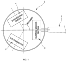
- FIG. 1 illustrates an injection stretch blow molding machine 1 that implements the present invention.
- the injection stretch blow molding machine 1 includes: an injection molding section 3 configured to inject mold a preform by supplying a molten resin from an injection apparatus 2; a blow molding section 4 configured to stretch the preform, which has been injection molded by the injection molding section 3, and to blow mold a hollow molded article by blowing blow air into the preform; and an ejection section 5 configured to eject the hollow molded article, which has been blow molded by the blow molding section 4, to the outside of the injection stretch blow molding machine 1.
- the injection molding section 3, the blow molding section 4, and the ejection section 5 are located at respective positions at constant angular intervals in the rotation direction of a not-illustrated rotary plate with lip molds.
- An arrow in FIG. 1 shows the rotation direction of the rotary plate and the transferring direction of the lip molds.
- the rotation of the rotary plate is able to position the lip molds directly above the respective, injection molding section 3, blow molding section 4, and ejection section 5. Then, the lip molds repeat rotation at a constant rotation angle and ascending/descending actions. By doing so, the preform is transferred from the injection molding section 3 to the blow molding section 4 by the lip mold, and the hollow molded article is transferred from the blow molding section 4 to the ejection section 5.
- the lip mold at the ejection section 5 releases the hollow molded article, and the rotation of the rotary plate can return the lip mold, which has released the hollow molded article, to the injection molding section 3.
- the injection molding section 3 has an injection molding mold which is constituted by combining the lip mold with an upper mold (injection core mold) and a lower mold (injection cavity mold).
- the lower mold, or both the lower and upper molds are provided with a cooling circuit for circulating a refrigerant adjusted to a predetermined temperature.
- a molten resin is injection molded with the injection molding mold, in which the upper mold and the lower mold are closed and clamped under high pressure, and is brought into contact with the injection molding mold for cooling.
- the upper mold and the lower mold are opened, and the rotary plate ascends while the preform is supported by the lip mold. Furthermore, the rotary plate rotates so that the transfer of the lip molds allows the preform to be transferred to the blow molding section 4.
- the blow molding section 4 has a blow molding mold which is constituted by combining the lip mold with blow molds which are composed of paired split molds.
- the blow molding section 4 includes a stretching rod configured to enter the inside of the preform supported by the lip mold between the blow molds, and a blowing apparatus configured to supply blow air into the preform with pressure. Then, the preform is stretched by the stretching rod and blown with blow air to blow mold the hollow molded article.
- the hollow molded article is released by the ascending action of the rotary plate while the blow molds are opened after blow molding, and the rotary plate rotates so that the hollow molded article, which is still supported by the lip mold, is transferred to the ejection section 5.
- the hollow molded article which is being held by the lip mold is released. Then, the hollow molded article detached from the lip mold is ejected to the outside of the injection stretch blow molding machine 1. Furthermore, the lip mold which has released the hollow molded article is transferred to the injection molding section 3 by the rotation of the rotary plate, so that it is incorporated into the injection molding mold as described above.
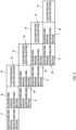
- the method for producing a hollow molded article according to the present embodiment utilizes the above-mentioned injection stretch blow molding machine 1, and corresponds to a hollow molded article producing process 6 in which the lip molds are sequentially transferred to positions of the injection molding section 3, the blow molding section 4, and the ejection section 5 to produce the hollow molded article.
- the hollow molded article producing process 6 includes, as illustrated in FIG. 2 , an injection molding process 7 for injection molding a preform in the injection molding section 3; a blow molding process 8 for blow molding a hollow molded article by stretching the preform, which has been molded in the injection molding process 7, and by blowing blow air thereinto in the blow molding section 4; and an ejection process 9 for ejecting the hollow molded article, which has been molded in the blow molding process 8, to the outside of the molding machine by releasing it from the lip mold in the ejection section 5.
- the injection stretch blow molding machine 1 mentioned as the present embodiment is a molding machine configured to produce a cup-shaped wide-mouth hollow molded article. Furthermore, a preform for obtaining a cup-shaped hollow molded article is injection molded in a bowl shape with a lip portion having a wide opening.
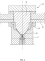
- FIG. 3 shows an injection molding mold 10 for use in injection molding a bowl-shaped preform 15.
- the illustrated injection molding mold 10 includes a lower mold 11; a lip mold 13 which is assembled to a rotary plate 12 and is superimposed on the lower mold 11; and an upper mold 14 which is lowered so as to enter the lower mold 11 through the lip mold 13.
- the injection molding process 7 repeated in the injection molding section 3 includes the following multiple steps (processes) (see FIG. 4 ):
- the lower mold 11 or both the lower mold 11 and the upper mold 14 are provided with a cooling unit (not illustrated) which has a cooling circuit for circulating the refrigerant into the mold, so that the lower mold 11 and the upper mold 14 are constantly cooled.
- the injection molding process 7 includes an injection cooling process 16 consisting of the injection step e and the cooling step f.
- the molten resin which is supplied into a filling space portion of the injection molding mold 10, spreads over the entire filling space portion while being in contact with the inner surface of the injection molding mold 10, so that the set amount of the molten resin is filled in a pressurized state.
- the cooling step f after the supply of the molten resin is completed, the preform 15 is subsequently cooled from the inner surface side of the injection molding mold 10.
- the preform 15 in the molten state comes into contact with the injection molding mold 10 which is constantly cooled. As a result, a portion of the surface layer of the preform 15 is solidified.
- the molten resin (in a softened state) in a high temperature is still present in the inner layer of the preform 15, and heat from the inner layer is transferred toward the surface layer.
- the timing of releasing the preform 15 from the injection molding mold 10 is made earlier.
- the time for the injection cooling process 16 is ensured until the hardness of the preform, where the shape of the preform does not collapse in the middle of being conveyed to the blow molding section 4, is ensured.
- the injection molding process 7 includes a preform conveyance process 17 of conveying the preform 15 which has been released from the injection molding mold 10 to the blow molding section 4.
- the surface layer of the preform 15 is solidified, and the shape of the preform 15 is maintained.
- the preform 15 is not yet cooled from the injection molding mold 10, but heat from the inner layer is transferred to the surface layer to raise the temperature of the surface layer and soften the surface layer while being conveyed to the blow molding section 4.
- the injection molding process 7 is repeated in the injection molding section 3.
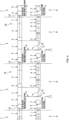
- FIG. 5 shows a blow molding mold 18.
- the lip mold 13 which has been transferred to the blow molding section 4, overlaps above the paired blow molds 19 which are closed. Furthermore, the blow core mold 21 which supports the stretching rod 20 is superimposed on the lip mold 13, and the stretching rod 20 is lowered toward the bottom of the blow molds 19 through the lip mold 13.
- the blow core mold 21 is provided with a supplying unit 22 configured to supply blow air so as to pass around the stretching rod 20.
- the lip mold 13 attached to the rotary plate 12 transfers the preform 15 in the preform conveyance process 17, and the blow molding mold 18 is then clamped. At this time, the stretching rod 20 supported by the blow core mold 21 enters the inside of the preform 15.
- the blow molding process 8 in the blow molding section 4 includes, first, the above-mentioned step a of conveying the hollow molded article, which has been blow molded in a preceding process, toward the ejection section 5, the mold closure starting step b for the blow molds 19, and the clamping step c for the blow molds 19.
- the preform 15, which has been injection molded in the injection molding process 7, is positioned above the blow molds 19 while being supported by the lip mold, and the preform 15 is disposed between the blow molds 19 by descending action of the rotary plate 12 (step d).
- the blow core mold 21 is lowered, so that the stretching rod 20 is located directly above the preform 15. Then, the stretching rod 20, which is lowered, stretches the preform 15 while pressing down the bottom of the preform 15.
- the blowing apparatus blows air into the preform 15 to blow mold the hollow molded article (step f).
- the blow air is discharged to bring the interior of the hollow molded article to atmospheric pressure, and the clamping force applied to the blow molding mold 18 is reduced to open the blow molding mold 18 (steps g, h, and i).
- a cooling unit 24 is provided at a tip (lower end portion) 23, formed of a metal material, of the stretching rod 20 in the blow molding section 4.
- the cooling unit 24 cools the tip 23 so that the bottom of the preform 15 which is in contact therewith is cooled. This prevents the bottom from rupturing during stretching while suppressing softening of the bottom, and also stretches the side of the preform 15 by pressing down the bottom which does not rupture.
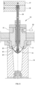
- the cooling unit 24 includes a cooling circuit 25 which passes through the interior of the tip 23 of the stretching rod 20 as illustrated in FIG. 6 .
- a refrigerant at 50°C to 90°C is allowed to flow through the cooling circuit 25 to cool the bottom of the preform 15 each time the tip 23 comes into contact with the bottom.
- a return pipe line connected to a refrigerant source is provided within a rod support plate 26 with the stretching rod 20 attached, and a supply pipe line from the refrigerant source is provided within a mounting plate 27 overlapping the upper surface of the rod support plate 26.
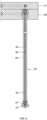
- a rod body 28 of the stretching rod 20, which is supported by the rod support plate 26, is formed in a pipe shape.
- the cooling circuit 25 is formed by inserting a conduit 30, which communicates with the supply pipe line of the mounting plate 27, into an inner passage 29, which extends from the upper portion of the rod body 28 (from the rod support plate 26 side) to the lower portion (to the tip 23 side).
- a refrigerant is fed into the conduit 30 from the mounting plate 27 side, is passed through the tip 23, raised between the outer surface of the conduit 30 and the inner surface of the inner passage 29 to reach the return pipe line of the rod support plate 26, and returns from the return pipe line to the refrigerant source.
- the temperature of the refrigerant passing through the cooling circuit 25 to a temperature ranging from 50°C to 90°C.
- the refrigerant adjusted to the foregoing temperature range can suppress softening of the bottom of the preform 15 which is in contact with the tip 23 of the stretching rod 20.
- the bottom of the preform 15 is not over stretched. That is, the stretching of the bottom of the preform 15 is suppressed, and the side of the preform 15, which is not in contact with the stretching rod 20, is appropriately stretched, so that the rupture of the bottom can be prevented.
- the injection cooling time of the preform 15 is shorter. Since the preform 15 in this state is transferred to the blow molding section 4, heat is transferred from the inner layer of the preform 15, which is still in the softened state at the time when the preform 15 is located inside the blow molding mold 18, to the surface layer, so that the side of the preform 15 is in a state which is ready to be stretched.
- the tip 23 of the stretching rod 20 presses down the bottom of the preform 15, the entire side of the preform 15 is properly stretched. Therefore, the resulting hollow molded article has no large variation in wall thickness in the bottom circumferential direction because the bottom is also appropriately stretched in the plane direction.
- the process proceeds to the ejection process 9.
- the hollow molded article is pulled up from the blow molding mold 18 which is opened while being supported by the lip mold 13, and is transferred to the ejection section 5 by the rotation of the rotary plate 12. Then, after the rotary plate 12 stops, the lip mold 13 is opened to release the hollow molded article, which is then ejected to the outside of the molding machine.
- the lip mold 13 is closed and the rotary plate 12 rotates to move toward the injection molding section 3, thereby completing the ejection process 9.
- test conditions were as follows.
- a preform 15 was blow molded using a blow molding section 4 provided with these stretching rods 20 to obtain a hollow molded article with a weight of 25.2 g.
- the sample using the refrigerant at 30°C is referred to as Comparative Example 1, the sample using the refrigerant at 40°C as Comparative Example 2, the sample using the refrigerant at 50°C as Example 1, the sample using the refrigerant at 60°C as Example 2, the sample using the refrigerant at 70°C as Example 3, the sample using the refrigerant at 80°C as Example 4, and the sample using the refrigerant at 90°C as Example 5.
- FIG. 7 shows the wall thickness measurement positions of each sample.
- FIG. 7 is a bottom view of a cup-shaped hollow molded article.
- the lines extending from the outside to the center of the bottom surface (bottom) of the hollow molded article are numbered 1 to 8.
- Line numbers 1 to 8 are numbered in clockwise order along the circumferential direction of the bottom surface (bottom) of the hollow molded article.
- reference signs A to F in FIG. 7 are arranged along each line of numbers 1 to 8 (along the radial direction of the bottom surface of the hollow molded article). That is, by measuring the wall thickness of the A portions of the line numbers 1 to 8, the difference in wall thickness (variation in wall thickness) of the circumferential region connecting the A portions of all the line numbers can be known.
- Comparative Example 1 Unit mm Line Number 1 2 3 4 5 6 7 8 Difference in Wall Thickness in Circumferential Direction A portion 0.38 0.39 0.43 0.39 0.33 0.37 0.37 0.36 0.10 B portion 1.13 1.07 1.14 1.04 0.94 1.00 1.00 1.01 0.20 C portion 0.94 0.78 0.96 0.78 0.69 0.75 0.78 0.81 0.27 D portion 0.77 0.86 1.09 1.05 0.99 1.00 0.97 0.75 0.34 E portion 1.16 1.21 1.21 1.17 1.13 1.21 1.24 1.17 0.11 F portion 0.88 0.87 0.94 0.91 0.98 0.97 0.89 0.88 0.11 Average of Differences in Wall Thickness 0.19 [Table 2] Comparative Example 2 Unit: mm Line Number 1 2 3 4 5 6 7 8 Difference in Wall Thickness in Circumferential Direction A portion 0.34 0.36 0.41 0.40 0.31 0.36 0.32 0.31 0.10 B portion 0.90 0.88 0.97 0.87 0.82 0.89 0.85 0.89 0.15 C portion 0.80 0.58 0.74 0.57 0.53 0.60 0.53
- the “difference in wall thickness in the circumferential direction” indicates the difference in wall thickness of the A portions of the line numbers 1 to 8 (the value obtained by subtracting the minimum wall thickness from the maximum wall thickness of the A portions), the difference in wall thickness of the B portions of the line numbers 1 to 8, the difference in wall thickness of the C portions of the line numbers 1 to 8, the difference in wall thickness of the D portions of the line numbers 1 to 8, the difference in wall thickness of the E portions of the line numbers 1 to 8, and the difference in wall thickness of the F portions of the line numbers 1 to 8.
- the "average difference in wall thickness" shown at the bottom of each table corresponds to the average value of the difference in wall thickness in the circumferential direction corresponding to the A to F portions (the differences in wall thickness of the A to F portions are summed and divided by the number of measurement areas, i.e., 6 (the number of the A to F portions) to obtain the values).
- the average difference in wall thickness in the circumferential direction in Comparative Examples 1 and 2 was about 0.2 mm.
- the average difference in wall thickness in the circumferential direction in Examples 1 to 5 was about 0.1 mm. That is, it was shown that the variation (uneven wall thickness) in the sample in the bottom circumferential direction using the refrigerant at 50°C to 90°C was smaller than that of the sample when using the refrigerant at 30°C to 40°C.
- the average difference in wall thickness in the circumferential direction in Examples 3 to 5 was 0.1 mm or less, indicating that the variation in wall thickness (uneven wall thickness) in the bottom circumferential direction was even smaller.
Landscapes
- Engineering & Computer Science (AREA)
- Mechanical Engineering (AREA)
- Manufacturing & Machinery (AREA)
- Physics & Mathematics (AREA)
- Thermal Sciences (AREA)
- Blow-Moulding Or Thermoforming Of Plastics Or The Like (AREA)
Claims (4)
- Verfahren zur Herstellung eines hohlen Formkörpers, umfassend:ein Spritzgießprozess (7) zum Spritzgießen eines Vorformlings (15) in einer Spritzgießform (10); undein Blasformprozess (8) zum Blasformen des Vorformlings (15) in einer Blasform-Form (18), um einen hohlen Formkörper zu erhalten, wobeider Spritzgießprozess (7) einen Spritzkühlprozess (16) enthält, bei dem der Vorformling (15) mit einer Spritzgießform (10) in Kontakt gebracht wird, um eine Oberflächenschicht des Vorformlings (15) zu verfestigen; undferner einen Prozess zum Befördern des Vorformlings (15) enthält, bei dem der Vorformling (15) aus der Spritzgießform (10) gelöst und der Vorformling (15) zu einer Blasform-Form (18) befördert wird, wobei sich der Vorformling (15) in einem Zustand befindet, in dem die Oberflächenschicht des Vorformlings (15) durch Aufnahme von Wärme aus einer inneren Schicht des Vorformlings (15) erweicht wird;wobei es der Blasformprozess (8) ermöglicht, dass eine Spitze (23) eines auf eine Temperatur im Bereich von 50 °C bis 90 °C gekühlten Streckstabs (20) in Kontakt mit einem Boden des Vorformlings (15) gebracht wird, der zu der Blasform-Form (18) in einem Zustand befördert wird, in dem die Temperatur der Oberflächenschicht des Vorformlings (15) erhöht und durch Aufnahme von Wärme von der inneren Schicht des Vorformlings (15) in dem Beförderungsprozess des Vorformlings (15) erweicht wird, und zwar in einem erweichten Zustand, der in dem Spritzgießprozess (7) erhalten wird, und um den Boden des Vorformlings (15) nach unten zu drücken, während der Boden abgekühlt wird,dadurch gekennzeichnet, dassdas Verfahren eine Spritzstreckblasmaschine verwendet, die Folgendes umfasst- einen Spritzgießabschnitt (3), in dem die Spritzgießform (10), die eine obere Form (14), eine untere Form (11) und eine Lippenform (13) kombiniert, zum Spritzgießen des Vorformlings (15) angeordnet und konfiguriert ist; und- einen Blasformabschnitt (4), in dem die Blasform-Form (18), die eine Blasform (19) und die Lippenform (13) kombiniert, so angeordnet ist, dass sie den Streckstab (20) enthält, der so konfiguriert ist, dass er den Vorformling (15) streckt, der durch den Spritzgießabschnitt (3) spritzgegossen wurde, der so konfiguriert ist, dass er den hohlen Formkörper blasformt,- einen Ausstoßabschnitt (5), der so konfiguriert ist, dass er den hohlen Formkörper, der in dem Blasformabschnitt (4) geformt wurde, aus der Lippenform (13) ausstößt und ihn außerhalb der Maschine entlädt,wobei der Spritzgießabschnitt (3), der Blasformabschnitt (4) und der Ausstoßabschnitt (5) auf einem Drehteller (12) angeordnet sind.
- Verfahren zur Herstellung eines hohlen Formkörpers nach Anspruch 1, wobei die Spitze (23) des Streckstabs (20) auf eine Temperatur im Bereich von 70 °C bis 90 °C abgekühlt wird.
- Spritzstreckblasmaschine (1), umfassend:einen Spritzgießabschnitt (3), in dem eine Spritzgießform (10) angeordnet ist, die zum Spritzgießen eines Vorformlings (15) konfiguriert ist; undeinen Blasformabschnitt (4), in dem eine Blasform-Form (18) angeordnet ist, die einen Streckstab (20) enthält, der so konfiguriert ist, dass er den Vorformling (15) streckt, der durch den Spritzgießabschnitt (3) spritzgegossen wurde, der so konfiguriert ist, dass er den hohlen Formkörper blasformt,wobeider Spritzgießabschnitt (3), der einen Bereich enthält, in dem ein Spritzkühlprozess (16), bei dem der Vorformling (15) mit einer Spritzgießform (10) in Kontakt gebracht werden kann, um eine Oberflächenschicht des Vorformlings (15) zu verfestigen; und,ferner einen Bereich enthält, in dem ein Prozess zum Befördern des Vorformlings (15) den Vorformling (15) aus der Spritzgießform (10) löst und den Vorformling (15) zu einer Blasform-Form (18) befördert, wobei sich der Vorformling (15) in einem Zustand befindet, in dem die Oberflächenschicht des Vorformlings (15) durch Aufnahme von Wärme aus einer inneren Schicht des Vorformlings (15) erweicht wird;der Blasformabschnitt (4), der einen Bereich enthält, in dem der aus der Spritzgießform (10) freigegebene Vorformling (15) in der Blasform-Form (18) in einem Zustand platziert wird, in dem die Oberflächenschicht des Vorformlings (15) durch Aufnahme von Wärme von der inneren Schicht des Vorformlings (15) erweicht wird,wobeider Streckstab (20) mit einer Kühleinheit (24) zum Kühlen der Spitze (23) bereitgestellt ist, die den Boden des Vorformlings (15) berührt, der von der Spritzgießform (10) zur Blasform-Form (18) in einem Zustand befördert wird, in dem die Temperatur der Oberflächenschicht des Vorformlings (15) durch Aufnahme von Wärme von der inneren Schicht des Vorformlings (15) auf eine Temperatur im Bereich von 50 °C bis 90 °C erhöht und erweicht wird,dadurch gekennzeichnet, dassdie Spritzgießform (10) eine obere Form (14), eine untere Form (11) und eine Lippenform (13) kombiniert;die Blasform-Form (18) eine Blasform (19) und die Lippenform (13) kombiniert;in der Spritzstreckblasmaschine ein Ausstoßabschnitt (5) bereitgestellt ist, der so konfiguriert ist, dass er den in dem Blasformabschnitt geformten hohlen Formkörper aus der Lippenform (13) ausstößt und ihn außerhalb der Maschine entlädt, wobei der Spritzgießabschnitt, der Blasformabschnitt und der Ausstoßabschnitt auf einem Drehteller (12) angeordnet sind.
- Spritzstreckblasmaschine (1) nach Anspruch 3, wobei die Spitze (23) des Streckstabs (20) auf eine Temperatur im Bereich von 70 °C bis 90 °C abgekühlt wird.
Applications Claiming Priority (1)
| Application Number | Priority Date | Filing Date | Title |
|---|---|---|---|
| JP2021170110A JP7039089B1 (ja) | 2021-10-18 | 2021-10-18 | 中空成形体の製造方法及び射出延伸ブロー成形機 |
Publications (3)
| Publication Number | Publication Date |
|---|---|
| EP4166303A1 EP4166303A1 (de) | 2023-04-19 |
| EP4166303C0 EP4166303C0 (de) | 2025-04-23 |
| EP4166303B1 true EP4166303B1 (de) | 2025-04-23 |
Family
ID=81214280
Family Applications (1)
| Application Number | Title | Priority Date | Filing Date |
|---|---|---|---|
| EP22201367.4A Active EP4166303B1 (de) | 2021-10-18 | 2022-10-13 | Verfahren zur herstellung eines hohlen formkörpers und spritzstreckblasmaschine |
Country Status (8)
| Country | Link |
|---|---|
| US (1) | US12103218B2 (de) |
| EP (1) | EP4166303B1 (de) |
| JP (1) | JP7039089B1 (de) |
| KR (1) | KR102581224B1 (de) |
| CN (1) | CN115990989A (de) |
| CA (1) | CA3177583A1 (de) |
| ES (1) | ES3028814T3 (de) |
| TW (1) | TW202330237A (de) |
Families Citing this family (2)
| Publication number | Priority date | Publication date | Assignee | Title |
|---|---|---|---|---|
| CN117841338B (zh) * | 2024-01-11 | 2025-03-14 | 鸿利达精密组件(中山)有限公司 | 用于中空双层瓶的注吹模具、注吹设备以及成型方法 |
| JP7672757B1 (ja) * | 2024-09-05 | 2025-05-08 | 株式会社青木固研究所 | 中空成形体の成形方法、これに用いる延伸ロッドおよび射出延伸ブロー成形機 |
Citations (2)
| Publication number | Priority date | Publication date | Assignee | Title |
|---|---|---|---|---|
| US5578262A (en) * | 1994-04-07 | 1996-11-26 | Marcus; Paul | Injection blow molding having reduced molding cycle times |
| WO2020209287A1 (ja) * | 2019-04-09 | 2020-10-15 | 日精エー・エス・ビー機械株式会社 | 樹脂製容器の製造装置 |
Family Cites Families (13)
| Publication number | Priority date | Publication date | Assignee | Title |
|---|---|---|---|---|
| US3979491A (en) * | 1971-11-24 | 1976-09-07 | Continental Can Company, Inc. | Process for the manufacture of an oriented container |
| JPS5131528A (ja) * | 1974-09-09 | 1976-03-17 | Sanyo Electric Co | Gakushusochi |
| JPS6061228A (ja) | 1983-09-14 | 1985-04-09 | Mitsubishi Plastics Ind Ltd | プラスチックボトルの成形方法 |
| JPH0671762B2 (ja) * | 1991-04-30 | 1994-09-14 | 日精エー・エス・ビー機械株式会社 | 厚肉の底壁を有する中空体の射出延伸吹込成形方法 |
| US5290506A (en) * | 1991-04-30 | 1994-03-01 | Nissei Asb Machine Co., Ltd. | Process of injection stretch blow molding hollow article having thick-walled bottom |
| US6682690B2 (en) * | 2001-02-01 | 2004-01-27 | Schmalbach-Lubreca Ag | Core rod positioning method |
| JP2004090425A (ja) | 2002-08-30 | 2004-03-25 | Aoki Technical Laboratory Inc | 薄肉プリフォーム及びその射出延伸ブロー成形方法 |
| JP4655602B2 (ja) | 2004-11-30 | 2011-03-23 | 凸版印刷株式会社 | 黒色マット調延伸容器の製造方法 |
| DE102008047891A1 (de) | 2008-09-18 | 2010-03-25 | Krones Ag | Temperierte Reckstange |
| CN111465481B (zh) * | 2017-09-29 | 2022-12-23 | 日精Asb机械株式会社 | 吹塑成型方法和吹塑成型装置 |
| JP6505344B1 (ja) * | 2017-10-19 | 2019-04-24 | 日精エー・エス・ビー機械株式会社 | 樹脂製の容器の製造方法、金型ユニットおよび成形機 |
| JP6840393B2 (ja) | 2018-04-19 | 2021-03-10 | 株式会社青木固研究所 | 射出延伸ブロー成形機と中空成形体の製造方法 |
| CN113825617A (zh) * | 2019-04-09 | 2021-12-21 | 日精Asb机械株式会社 | 树脂容器制造方法 |
-
2021
- 2021-10-18 JP JP2021170110A patent/JP7039089B1/ja active Active
-
2022
- 2022-09-01 CN CN202211066002.1A patent/CN115990989A/zh active Pending
- 2022-09-29 CA CA3177583A patent/CA3177583A1/en active Pending
- 2022-09-29 TW TW111136947A patent/TW202330237A/zh unknown
- 2022-10-06 KR KR1020220127631A patent/KR102581224B1/ko active Active
- 2022-10-07 US US17/961,990 patent/US12103218B2/en active Active
- 2022-10-13 ES ES22201367T patent/ES3028814T3/es active Active
- 2022-10-13 EP EP22201367.4A patent/EP4166303B1/de active Active
Patent Citations (2)
| Publication number | Priority date | Publication date | Assignee | Title |
|---|---|---|---|---|
| US5578262A (en) * | 1994-04-07 | 1996-11-26 | Marcus; Paul | Injection blow molding having reduced molding cycle times |
| WO2020209287A1 (ja) * | 2019-04-09 | 2020-10-15 | 日精エー・エス・ビー機械株式会社 | 樹脂製容器の製造装置 |
Also Published As
| Publication number | Publication date |
|---|---|
| CA3177583A1 (en) | 2023-04-25 |
| US20230118659A1 (en) | 2023-04-20 |
| KR20230055360A (ko) | 2023-04-25 |
| JP7039089B1 (ja) | 2022-03-22 |
| CN115990989A (zh) | 2023-04-21 |
| JP2023060478A (ja) | 2023-04-28 |
| EP4166303A1 (de) | 2023-04-19 |
| EP4166303C0 (de) | 2025-04-23 |
| KR102581224B1 (ko) | 2023-09-21 |
| TW202330237A (zh) | 2023-08-01 |
| ES3028814T3 (en) | 2025-06-20 |
| US12103218B2 (en) | 2024-10-01 |
Similar Documents
| Publication | Publication Date | Title |
|---|---|---|
| US12233588B2 (en) | Resin container manufacturing apparatus, temperature adjusting device, resin container manufacturing method, and temperature adjusting method | |
| EP4166303B1 (de) | Verfahren zur herstellung eines hohlen formkörpers und spritzstreckblasmaschine | |
| US7384587B2 (en) | Method for post mold cooling of plastic pieces | |
| US6332770B1 (en) | Apparatus for localized preform cooling outside the mold | |
| US20240217158A1 (en) | Resin container manufacturing method | |
| CN102802917A (zh) | 用于加工具有特殊形状的预型件的方法和装置 | |
| US11260576B2 (en) | Injection stretch blow molding machine and method for molding polythylene container | |
| EP3616883B1 (de) | Verfahren zur herstellung eines hohlen formkörpers | |
| JPH0890642A (ja) | 大型容器の延伸吹込成形方法及び装置 | |
| US11958230B2 (en) | Method for producing resin container and device for producing resin container | |
| HK40084213A (en) | Method for producing hollow molded article and injection stretch blow molding machine | |
| JP2569241B2 (ja) | ブロー成形方法 | |
| PL158199B1 (en) | Thermoplastic moulded pieces production method and a device for their production | |
| HK40055456A (en) | Injection stretch blow molding machine and method for molding polythylene container | |
| HK40055456B (en) | Injection stretch blow molding machine and method for molding polythylene container | |
| CN119095711A (zh) | 保压装置、注射装置以及树脂材料的注射方法 | |
| JPH06126821A (ja) | 耐熱性容器の成形装置 |
Legal Events
| Date | Code | Title | Description |
|---|---|---|---|
| PUAI | Public reference made under article 153(3) epc to a published international application that has entered the european phase |
Free format text: ORIGINAL CODE: 0009012 |
|
| STAA | Information on the status of an ep patent application or granted ep patent |
Free format text: STATUS: REQUEST FOR EXAMINATION WAS MADE |
|
| 17P | Request for examination filed |
Effective date: 20221013 |
|
| AK | Designated contracting states |
Kind code of ref document: A1 Designated state(s): AL AT BE BG CH CY CZ DE DK EE ES FI FR GB GR HR HU IE IS IT LI LT LU LV MC ME MK MT NL NO PL PT RO RS SE SI SK SM TR |
|
| STAA | Information on the status of an ep patent application or granted ep patent |
Free format text: STATUS: EXAMINATION IS IN PROGRESS |
|
| 17Q | First examination report despatched |
Effective date: 20240226 |
|
| GRAP | Despatch of communication of intention to grant a patent |
Free format text: ORIGINAL CODE: EPIDOSNIGR1 |
|
| STAA | Information on the status of an ep patent application or granted ep patent |
Free format text: STATUS: GRANT OF PATENT IS INTENDED |
|
| RIC1 | Information provided on ipc code assigned before grant |
Ipc: B29L 31/00 20060101ALN20241104BHEP Ipc: B29C 49/70 20060101ALN20241104BHEP Ipc: B29C 49/64 20060101ALN20241104BHEP Ipc: B29C 49/02 20060101ALN20241104BHEP Ipc: B29C 49/28 20060101ALN20241104BHEP Ipc: B29C 49/06 20060101ALN20241104BHEP Ipc: B29C 49/78 20060101ALI20241104BHEP Ipc: B29C 49/42 20060101ALI20241104BHEP Ipc: B29C 49/12 20060101AFI20241104BHEP |
|
| INTG | Intention to grant announced |
Effective date: 20241122 |
|
| GRAS | Grant fee paid |
Free format text: ORIGINAL CODE: EPIDOSNIGR3 |
|
| GRAA | (expected) grant |
Free format text: ORIGINAL CODE: 0009210 |
|
| STAA | Information on the status of an ep patent application or granted ep patent |
Free format text: STATUS: THE PATENT HAS BEEN GRANTED |
|
| AK | Designated contracting states |
Kind code of ref document: B1 Designated state(s): AL AT BE BG CH CY CZ DE DK EE ES FI FR GB GR HR HU IE IS IT LI LT LU LV MC ME MK MT NL NO PL PT RO RS SE SI SK SM TR |
|
| REG | Reference to a national code |
Ref country code: GB Ref legal event code: FG4D |
|
| REG | Reference to a national code |
Ref country code: CH Ref legal event code: EP |
|
| REG | Reference to a national code |
Ref country code: DE Ref legal event code: R096 Ref document number: 602022013477 Country of ref document: DE |
|
| REG | Reference to a national code |
Ref country code: IE Ref legal event code: FG4D |
|
| U01 | Request for unitary effect filed |
Effective date: 20250514 |
|
| U07 | Unitary effect registered |
Designated state(s): AT BE BG DE DK EE FI FR IT LT LU LV MT NL PT RO SE SI Effective date: 20250519 |
|
| REG | Reference to a national code |
Ref country code: ES Ref legal event code: FG2A Ref document number: 3028814 Country of ref document: ES Kind code of ref document: T3 Effective date: 20250620 |
|
| PG25 | Lapsed in a contracting state [announced via postgrant information from national office to epo] |
Ref country code: NO Free format text: LAPSE BECAUSE OF FAILURE TO SUBMIT A TRANSLATION OF THE DESCRIPTION OR TO PAY THE FEE WITHIN THE PRESCRIBED TIME-LIMIT Effective date: 20250723 Ref country code: GR Free format text: LAPSE BECAUSE OF FAILURE TO SUBMIT A TRANSLATION OF THE DESCRIPTION OR TO PAY THE FEE WITHIN THE PRESCRIBED TIME-LIMIT Effective date: 20250724 |
|
| PG25 | Lapsed in a contracting state [announced via postgrant information from national office to epo] |
Ref country code: PL Free format text: LAPSE BECAUSE OF FAILURE TO SUBMIT A TRANSLATION OF THE DESCRIPTION OR TO PAY THE FEE WITHIN THE PRESCRIBED TIME-LIMIT Effective date: 20250423 |
|
| PG25 | Lapsed in a contracting state [announced via postgrant information from national office to epo] |
Ref country code: HR Free format text: LAPSE BECAUSE OF FAILURE TO SUBMIT A TRANSLATION OF THE DESCRIPTION OR TO PAY THE FEE WITHIN THE PRESCRIBED TIME-LIMIT Effective date: 20250423 |
|
| PG25 | Lapsed in a contracting state [announced via postgrant information from national office to epo] |
Ref country code: RS Free format text: LAPSE BECAUSE OF FAILURE TO SUBMIT A TRANSLATION OF THE DESCRIPTION OR TO PAY THE FEE WITHIN THE PRESCRIBED TIME-LIMIT Effective date: 20250723 |
|
| PG25 | Lapsed in a contracting state [announced via postgrant information from national office to epo] |
Ref country code: IS Free format text: LAPSE BECAUSE OF FAILURE TO SUBMIT A TRANSLATION OF THE DESCRIPTION OR TO PAY THE FEE WITHIN THE PRESCRIBED TIME-LIMIT Effective date: 20250823 |
|
| U20 | Renewal fee for the european patent with unitary effect paid |
Year of fee payment: 4 Effective date: 20250929 |