EP4160066B1 - Soupape motorisée - Google Patents
Soupape motorisée Download PDFInfo
- Publication number
- EP4160066B1 EP4160066B1 EP22210461.4A EP22210461A EP4160066B1 EP 4160066 B1 EP4160066 B1 EP 4160066B1 EP 22210461 A EP22210461 A EP 22210461A EP 4160066 B1 EP4160066 B1 EP 4160066B1
- Authority
- EP
- European Patent Office
- Prior art keywords
- gear
- valve
- sun gear
- output shaft
- planetary gear
- Prior art date
- Legal status (The legal status is an assumption and is not a legal conclusion. Google has not performed a legal analysis and makes no representation as to the accuracy of the status listed.)
- Active
Links
- 230000007246 mechanism Effects 0.000 claims description 36
- 239000000463 material Substances 0.000 claims description 26
- 229920005989 resin Polymers 0.000 claims description 7
- 239000011347 resin Substances 0.000 claims description 7
- 229910052751 metal Inorganic materials 0.000 claims description 5
- 239000002184 metal Substances 0.000 claims description 5
- 239000000919 ceramic Substances 0.000 claims description 4
- 239000011521 glass Substances 0.000 claims description 4
- 230000002093 peripheral effect Effects 0.000 description 7
- 239000003507 refrigerant Substances 0.000 description 6
- 239000010935 stainless steel Substances 0.000 description 5
- 229910001220 stainless steel Inorganic materials 0.000 description 5
- 239000004734 Polyphenylene sulfide Substances 0.000 description 4
- 238000006073 displacement reaction Methods 0.000 description 4
- 229920000069 polyphenylene sulfide Polymers 0.000 description 4
- 230000009471 action Effects 0.000 description 3
- 238000000465 moulding Methods 0.000 description 3
- 239000004033 plastic Substances 0.000 description 3
- 230000002028 premature Effects 0.000 description 3
- 230000000694 effects Effects 0.000 description 2
- 230000012447 hatching Effects 0.000 description 2
- 150000002739 metals Chemical class 0.000 description 2
- 238000000034 method Methods 0.000 description 2
- 230000009467 reduction Effects 0.000 description 2
- 230000004044 response Effects 0.000 description 2
- 238000003466 welding Methods 0.000 description 2
- 229910001297 Zn alloy Inorganic materials 0.000 description 1
- 230000000052 comparative effect Effects 0.000 description 1
- 230000008878 coupling Effects 0.000 description 1
- 238000010168 coupling process Methods 0.000 description 1
- 238000005859 coupling reaction Methods 0.000 description 1
- 230000005284 excitation Effects 0.000 description 1
- 239000012530 fluid Substances 0.000 description 1
- 239000000696 magnetic material Substances 0.000 description 1
- 230000008569 process Effects 0.000 description 1
- 238000005057 refrigeration Methods 0.000 description 1
Images


Classifications
-
- F—MECHANICAL ENGINEERING; LIGHTING; HEATING; WEAPONS; BLASTING
- F16—ENGINEERING ELEMENTS AND UNITS; GENERAL MEASURES FOR PRODUCING AND MAINTAINING EFFECTIVE FUNCTIONING OF MACHINES OR INSTALLATIONS; THERMAL INSULATION IN GENERAL
- F16K—VALVES; TAPS; COCKS; ACTUATING-FLOATS; DEVICES FOR VENTING OR AERATING
- F16K31/00—Actuating devices; Operating means; Releasing devices
- F16K31/02—Actuating devices; Operating means; Releasing devices electric; magnetic
- F16K31/04—Actuating devices; Operating means; Releasing devices electric; magnetic using a motor
-
- F—MECHANICAL ENGINEERING; LIGHTING; HEATING; WEAPONS; BLASTING
- F16—ENGINEERING ELEMENTS AND UNITS; GENERAL MEASURES FOR PRODUCING AND MAINTAINING EFFECTIVE FUNCTIONING OF MACHINES OR INSTALLATIONS; THERMAL INSULATION IN GENERAL
- F16C—SHAFTS; FLEXIBLE SHAFTS; ELEMENTS OR CRANKSHAFT MECHANISMS; ROTARY BODIES OTHER THAN GEARING ELEMENTS; BEARINGS
- F16C17/00—Sliding-contact bearings for exclusively rotary movement
- F16C17/04—Sliding-contact bearings for exclusively rotary movement for axial load only
- F16C17/08—Sliding-contact bearings for exclusively rotary movement for axial load only for supporting the end face of a shaft or other member, e.g. footstep bearings
-
- F—MECHANICAL ENGINEERING; LIGHTING; HEATING; WEAPONS; BLASTING
- F16—ENGINEERING ELEMENTS AND UNITS; GENERAL MEASURES FOR PRODUCING AND MAINTAINING EFFECTIVE FUNCTIONING OF MACHINES OR INSTALLATIONS; THERMAL INSULATION IN GENERAL
- F16K—VALVES; TAPS; COCKS; ACTUATING-FLOATS; DEVICES FOR VENTING OR AERATING
- F16K31/00—Actuating devices; Operating means; Releasing devices
- F16K31/44—Mechanical actuating means
- F16K31/53—Mechanical actuating means with toothed gearing
-
- F—MECHANICAL ENGINEERING; LIGHTING; HEATING; WEAPONS; BLASTING
- F16—ENGINEERING ELEMENTS AND UNITS; GENERAL MEASURES FOR PRODUCING AND MAINTAINING EFFECTIVE FUNCTIONING OF MACHINES OR INSTALLATIONS; THERMAL INSULATION IN GENERAL
- F16K—VALVES; TAPS; COCKS; ACTUATING-FLOATS; DEVICES FOR VENTING OR AERATING
- F16K1/00—Lift valves or globe valves, i.e. cut-off apparatus with closure members having at least a component of their opening and closing motion perpendicular to the closing faces
- F16K1/02—Lift valves or globe valves, i.e. cut-off apparatus with closure members having at least a component of their opening and closing motion perpendicular to the closing faces with screw-spindle
-
- F—MECHANICAL ENGINEERING; LIGHTING; HEATING; WEAPONS; BLASTING
- F16—ENGINEERING ELEMENTS AND UNITS; GENERAL MEASURES FOR PRODUCING AND MAINTAINING EFFECTIVE FUNCTIONING OF MACHINES OR INSTALLATIONS; THERMAL INSULATION IN GENERAL
- F16K—VALVES; TAPS; COCKS; ACTUATING-FLOATS; DEVICES FOR VENTING OR AERATING
- F16K1/00—Lift valves or globe valves, i.e. cut-off apparatus with closure members having at least a component of their opening and closing motion perpendicular to the closing faces
- F16K1/32—Details
-
- F—MECHANICAL ENGINEERING; LIGHTING; HEATING; WEAPONS; BLASTING
- F16—ENGINEERING ELEMENTS AND UNITS; GENERAL MEASURES FOR PRODUCING AND MAINTAINING EFFECTIVE FUNCTIONING OF MACHINES OR INSTALLATIONS; THERMAL INSULATION IN GENERAL
- F16K—VALVES; TAPS; COCKS; ACTUATING-FLOATS; DEVICES FOR VENTING OR AERATING
- F16K31/00—Actuating devices; Operating means; Releasing devices
- F16K31/02—Actuating devices; Operating means; Releasing devices electric; magnetic
- F16K31/04—Actuating devices; Operating means; Releasing devices electric; magnetic using a motor
- F16K31/047—Actuating devices; Operating means; Releasing devices electric; magnetic using a motor characterised by mechanical means between the motor and the valve, e.g. lost motion means reducing backlash, clutches, brakes or return means
-
- F—MECHANICAL ENGINEERING; LIGHTING; HEATING; WEAPONS; BLASTING
- F16—ENGINEERING ELEMENTS AND UNITS; GENERAL MEASURES FOR PRODUCING AND MAINTAINING EFFECTIVE FUNCTIONING OF MACHINES OR INSTALLATIONS; THERMAL INSULATION IN GENERAL
- F16K—VALVES; TAPS; COCKS; ACTUATING-FLOATS; DEVICES FOR VENTING OR AERATING
- F16K31/00—Actuating devices; Operating means; Releasing devices
- F16K31/44—Mechanical actuating means
- F16K31/50—Mechanical actuating means with screw-spindle or internally threaded actuating means
- F16K31/508—Mechanical actuating means with screw-spindle or internally threaded actuating means the actuating element being rotatable, non-rising, and driving a non-rotatable axially-sliding element
-
- F—MECHANICAL ENGINEERING; LIGHTING; HEATING; WEAPONS; BLASTING
- F25—REFRIGERATION OR COOLING; COMBINED HEATING AND REFRIGERATION SYSTEMS; HEAT PUMP SYSTEMS; MANUFACTURE OR STORAGE OF ICE; LIQUEFACTION SOLIDIFICATION OF GASES
- F25B—REFRIGERATION MACHINES, PLANTS OR SYSTEMS; COMBINED HEATING AND REFRIGERATION SYSTEMS; HEAT PUMP SYSTEMS
- F25B41/00—Fluid-circulation arrangements
- F25B41/30—Expansion means; Dispositions thereof
- F25B41/31—Expansion valves
- F25B41/34—Expansion valves with the valve member being actuated by electric means, e.g. by piezoelectric actuators
- F25B41/35—Expansion valves with the valve member being actuated by electric means, e.g. by piezoelectric actuators by rotary motors, e.g. by stepping motors
-
- H—ELECTRICITY
- H02—GENERATION; CONVERSION OR DISTRIBUTION OF ELECTRIC POWER
- H02K—DYNAMO-ELECTRIC MACHINES
- H02K7/00—Arrangements for handling mechanical energy structurally associated with dynamo-electric machines, e.g. structural association with mechanical driving motors or auxiliary dynamo-electric machines
- H02K7/06—Means for converting reciprocating motion into rotary motion or vice versa
-
- H—ELECTRICITY
- H02—GENERATION; CONVERSION OR DISTRIBUTION OF ELECTRIC POWER
- H02K—DYNAMO-ELECTRIC MACHINES
- H02K7/00—Arrangements for handling mechanical energy structurally associated with dynamo-electric machines, e.g. structural association with mechanical driving motors or auxiliary dynamo-electric machines
- H02K7/10—Structural association with clutches, brakes, gears, pulleys or mechanical starters
- H02K7/116—Structural association with clutches, brakes, gears, pulleys or mechanical starters with gears
-
- F—MECHANICAL ENGINEERING; LIGHTING; HEATING; WEAPONS; BLASTING
- F16—ENGINEERING ELEMENTS AND UNITS; GENERAL MEASURES FOR PRODUCING AND MAINTAINING EFFECTIVE FUNCTIONING OF MACHINES OR INSTALLATIONS; THERMAL INSULATION IN GENERAL
- F16C—SHAFTS; FLEXIBLE SHAFTS; ELEMENTS OR CRANKSHAFT MECHANISMS; ROTARY BODIES OTHER THAN GEARING ELEMENTS; BEARINGS
- F16C2361/00—Apparatus or articles in engineering in general
- F16C2361/91—Valves
-
- F—MECHANICAL ENGINEERING; LIGHTING; HEATING; WEAPONS; BLASTING
- F16—ENGINEERING ELEMENTS AND UNITS; GENERAL MEASURES FOR PRODUCING AND MAINTAINING EFFECTIVE FUNCTIONING OF MACHINES OR INSTALLATIONS; THERMAL INSULATION IN GENERAL
- F16H—GEARING
- F16H1/00—Toothed gearings for conveying rotary motion
- F16H1/28—Toothed gearings for conveying rotary motion with gears having orbital motion
- F16H2001/2872—Toothed gearings for conveying rotary motion with gears having orbital motion comprising three central gears, i.e. ring or sun gear, engaged by at least one common orbital gear mounted on an idling carrier
-
- F—MECHANICAL ENGINEERING; LIGHTING; HEATING; WEAPONS; BLASTING
- F16—ENGINEERING ELEMENTS AND UNITS; GENERAL MEASURES FOR PRODUCING AND MAINTAINING EFFECTIVE FUNCTIONING OF MACHINES OR INSTALLATIONS; THERMAL INSULATION IN GENERAL
- F16H—GEARING
- F16H25/00—Gearings comprising primarily only cams, cam-followers and screw-and-nut mechanisms
- F16H25/18—Gearings comprising primarily only cams, cam-followers and screw-and-nut mechanisms for conveying or interconverting oscillating or reciprocating motions
- F16H25/20—Screw mechanisms
- F16H2025/2062—Arrangements for driving the actuator
- F16H2025/2075—Coaxial drive motors
-
- F—MECHANICAL ENGINEERING; LIGHTING; HEATING; WEAPONS; BLASTING
- F16—ENGINEERING ELEMENTS AND UNITS; GENERAL MEASURES FOR PRODUCING AND MAINTAINING EFFECTIVE FUNCTIONING OF MACHINES OR INSTALLATIONS; THERMAL INSULATION IN GENERAL
- F16H—GEARING
- F16H25/00—Gearings comprising primarily only cams, cam-followers and screw-and-nut mechanisms
- F16H25/18—Gearings comprising primarily only cams, cam-followers and screw-and-nut mechanisms for conveying or interconverting oscillating or reciprocating motions
- F16H25/20—Screw mechanisms
- F16H2025/2062—Arrangements for driving the actuator
- F16H2025/2087—Arrangements for driving the actuator using planetary gears
-
- Y—GENERAL TAGGING OF NEW TECHNOLOGICAL DEVELOPMENTS; GENERAL TAGGING OF CROSS-SECTIONAL TECHNOLOGIES SPANNING OVER SEVERAL SECTIONS OF THE IPC; TECHNICAL SUBJECTS COVERED BY FORMER USPC CROSS-REFERENCE ART COLLECTIONS [XRACs] AND DIGESTS
- Y02—TECHNOLOGIES OR APPLICATIONS FOR MITIGATION OR ADAPTATION AGAINST CLIMATE CHANGE
- Y02B—CLIMATE CHANGE MITIGATION TECHNOLOGIES RELATED TO BUILDINGS, e.g. HOUSING, HOUSE APPLIANCES OR RELATED END-USER APPLICATIONS
- Y02B30/00—Energy efficient heating, ventilation or air conditioning [HVAC]
- Y02B30/70—Efficient control or regulation technologies, e.g. for control of refrigerant flow, motor or heating
Definitions
- the present invention relates to an electrically operated valve, and, for example, to an electrically operated valve incorporated in a refrigeration cycle and used for controlling the flow rate of a fluid such as a refrigerant.
- Patent Document 1 the present applicant has proposed an electrically operated valve in which the rotation of the rotor is decelerated by a planetary gear type deceleration mechanism and transmitted to a screw mechanism. Since the torque per unit rotation of the rotor becomes large in such an electrically operated valve, it can be used even under high load conditions, and the angular resolution of the valve opening degree per single drive pulse can be increased. Further documents disclosing the technological background to the invention are Patent Documents 2 to 6. In particular, Patent Document discloses an electrically operated valve according to the preamble of claim 1.
- the electrically operated valve includes a valve main body having a valve seat, a motor including a stator fixed to the valve main body and a rotor driven to rotate with respect to the stator, a planetary gear type deceleration mechanism configured to decelerate rotation of the rotor to transmit to an output gear, a valve member configured to be movable toward and away from the valve seat in an axial direction, and a feed screw mechanism configured to convert rotational movement of the output gear into movement of the valve member in the axial direction
- the planetary gear type deceleration mechanism includes a sun gear coupled to the rotor, a planetary gear engaged with the sun gear, a carrier for rotatably supporting the planetary gear, an annular ring gear engaged with the planetary gear, and a sliding member abutting against an axial end of the sun gear
- the output gear has a different number of teeth than the ring gear, and engages with the planetary gear
- the sliding member is made of
- the sliding member is preferably an annular body disposed between the sun gear and the carrier and is configured to slide with respect to at least one of them.
- the sliding member is an output shaft configured to slide with respect to the axial end of the sun gear, and is connected to the output gear to transmit a rotational force to the feed screw mechanism.
- the sun gear is made of a resin material
- the sliding member is made of a metal, ceramic, or glass material.
- the material on which those members are formed is referred to as the same type of material.
- a “different material” refers to materials which are not the same material; that is, when “adhesion wear” does not occur when two members are slid together, the material of one member corresponds to a different material with respect to the material of the other member.
- Examples of different types of materials include materials of different categories when arbitrary materials are classified into categories such as, for example, metals, resins, ceramics, glass, and the like.
- the "axial direction” herein refers to the axial direction of the valve main body.
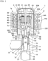
- FIG. 1 is an overall longitudinal cross-sectional view illustrating an electrically operated valve according to an example not being part of the claimed invention.
- FIG. 2 is an exploded perspective view of a planetary gear type deceleration mechanism used in the electrically operated valve illustrated in FIG. 1 , but a part thereof is cut away to facilitate better understanding.
- FIG. 3 is an exploded perspective view of the planetary gear and the carrier of the planetary gear type deceleration mechanism illustrated in FIG. 2 .
- the electrically operated valve 1 includes a drive unit 1a that is operated by an exciting action and which includes a motor composed of a stator 2 and a rotor assembly (hereinafter also called a motor) 8, a gear deceleration unit 1b which receives a rotational driving force from the drive unit 1a and performs gear deceleration to output a decelerated rotational force, and a feed screw mechanism 1c which converts the rotation decelerated by the gear deceleration unit 1b into a displacement in the axial direction using a screw action and outputs the displacement in the axial direction.
- a drive unit 1a that is operated by an exciting action and which includes a motor composed of a stator 2 and a rotor assembly (hereinafter also called a motor) 8, a gear deceleration unit 1b which receives a rotational driving force from the drive unit 1a and performs gear deceleration to output a decelerated rotational force, and a feed screw mechanism 1c which converts the rotation dec
- the can 30 is an air-tight container fixed to the valve main body 10 via a bearing member 68, and has a thin-walled cylindrical shape with a top.
- the drive unit 1a includes a stator 2 and a permanent-magnet type rotor assembly 8 which is rotationally driven by the stator 2.
- the stator 2 is an exciting device for an electric motor, and is fixedly disposed on the outer peripheral portion of the can 30 and is formed by molding a coil 140 wound around a bobbin integrally with resin.
- the rotor assembly 8 is rotatably supported inside the can 30.
- the stator 2 and the rotor assembly 8 constitute a stepping motor as one example of an electric motor.
- the stator 2 is detachably fitted to the can 30 by a mounting bracket 180 formed of a leaf spring.
- the dome portion 102 formed in the can 30 is elastically fitted into a hole 182 formed in the mounting bracket 180, thereby positioning the stator 2 relative to the can 30.
- Coils 140 are supplied by an external power source via a lead 142 for excitation of the stator 2.
- the valve main body 10 includes a valve chamber 14 formed therein, and also a bottom portion 15 formed with an orifice 16 that opens to the bottom surface of the valve main body 10.
- a pipe 22 that communicates with the side surface of the valve chamber 14 and a pipe 20 that communicates with the lower end of the orifice 16 are fixed to the valve main body 10.
- the gear deceleration unit 1b is composed of a planetary gear type deceleration mechanism (hereinafter abbreviated as a "deceleration mechanism") 40 for decelerating the rotational speed of the rotor assembly 8.
- a deceleration mechanism for decelerating the rotational speed of the rotor assembly 8.
- the deceleration mechanism 40 includes a sun gear 41 integrated with the rotor assembly 8, a plurality (three in this example) of planetary gears 43 engaged with the sun gear 41 that are elongated in the axial direction and rotatably supported by a carrier 42 formed by molding plastic, for example; a ring gear 44 that is arranged concentrically with the sun gear, fixedly supported with respect to the valve main body 10, and engaged with a part (the upper portion) of each planetary gear 43; and an output gear 45 formed in a cylindrical shape with a bottom that has a number of inner teeth slightly different from the number of teeth of the ring gear 44 (that is, in a profile-shifted relationship with the ring gear 44).
- the sun gear 41, the carrier 42, the ring gear 44, and the output gear 45 are formed of polyphenylene sulfide resin (PPS).
- the carrier 42 includes a lower disk 42b formed by implanting three column portions 42a in parallel on the outer periphery of the upper surface, and an annular plate 42c.
- a cylindrical protrusion 42d is formed on the upper end of each of the column portion 42a, and three corresponding through holes 42e are formed in the plate 42c.
- the planetary gear 43 formed of a zinc alloy has cylindrical convex portions 43a (only the upper end side is shown) at both ends in the axial direction.
- an axial hole 42f is formed in the lower disk 42b, and an axial hole 42g is formed in the plate 42c.
- the carrier 42 and the planetary gear 43 are assembled in the following manner. First, the planetary gear 43 is assembled to the lower disk 42b while the convex portion 43a is fitted to the axial hole 42f, and then the plate 42c is assembled such that the convex portion 43a is further fitted to the axial hole 42g, and the through hole 42e is engaged to the protrusion 42d of the column portion 42a. Thereafter, the plate 42c can be fixed to the column portion 42a by welding the protrusion 42d using, for example, an ultrasonic welding means. Since the axial holes 42f and 42g and the convex portion 43a are rotatable relative to each other, the planetary gear 43 is freely rotatable with respect to the carrier 42. It should be noted that the method of assembling the carrier 42 is not limited to the above.
- each planetary gear 43 engages with the ring gear 44, and at the same time engages with the inner teeth of the output gear 45 at one part (the lower portion).
- the rotational force of the rotor assembly 8 decelerated by the deceleration mechanism 40 is transmitted to the output shaft 46 (the driver) of the feed screw mechanism 1c through the output gear 45.
- An upper end of the output shaft 46 which is made of stainless steel, is coaxially fixed to the output gear 45.
- a cylindrical body 202 serving as a peripheral wall and a sun gear member 204 disposed at the center are integrally molded into a cylindrical shape with a top by a plastic material (here, PPS) that contains a magnetic material, and the rotor assembly 8 is rotatably disposed inside the can 30 by a shaft 201 that passes through the sun gear member 204 in the axial direction.
- PPS plastic material
- the sun gear 41 is formed on the outer periphery of a cylinder implanted in the center of the sun gear member 204.
- the ring gear 44 is, for example, a ring-shaped gear formed by molding plastic, and is fixed to an upper portion of a gear case 220, which is a cylindrical member whose lower portion is fitted to an upper portion of the valve main body 10, as illustrated in FIG. 1 .
- a sliding member which abuts against the axial direction end of the sun gear 41, and this sliding member is formed of a different material than the sun gear 41. Therefore, since wear (primarily adhesion wear) does not occur from sliding with the sun gear 41, it is possible to suppress the wear of the sun gear 41 without urging the sun gear 41 away from the carrier 42 using a spring member or the like.
- the sliding member will be specifically described.
- FIG. 4 is an enlarged view illustrating the inside of the can 30 in the configuration of FIG. 1 .
- the lower disk 42b of the carrier 42 has a circular opening 42h at the center thereof which passes through the shaft 201.
- the sun gear 41 through which the shaft 201 penetrates in the axial direction has an annular boss 41a at the tip (lower end), as partially illustrated in FIG. 2 .
- annular body 48 (illustrated by the hatching in FIG. 4 ) made of stainless steel is disposed between the annular boss 41a and the lower disk 42b.
- the annular body 48 that serves as the sliding member may be a washer that has the same diameter as the boss 41a.
- the feed screw mechanism 1c includes a cylindrical bearing 50, a screw shaft 52, and a ball 65.
- the lower end of the cylindrical bearing 50 is fitted into the valve main body 10, and is attached to the stepped portion 64 of the valve main body 10 in a state of being supported via the upper flange portion 75 so as not to be able to be pulled out from the valve main body 10 by means of press working or the like.
- the cylindrical bearing 50 supports the output gear 45 of the deceleration mechanism 40 from the lower side at its upper end surface, and the output shaft 46 of the deceleration mechanism 40 is inserted into the hollow upper portion of the cylindrical bearing 50.
- a male screw portion 53 formed on the outer periphery of the screw shaft 52 is screwed to the female screw portion 51 formed in the hollow lower portion of the cylindrical bearing 50.
- a convex portion 54 which is a flat driver portion, is provided on the screw shaft 52 and is inserted into a slit-shaped concave portion 55 formed in the lower end portion of the output shaft 46 of the deceleration mechanism 40, and transmits the rotation of the output shaft 46 to the screw shaft 52.
- a concave portion is formed in the lower end of the screw shaft 52, and the ball 65 is fixed to the screw shaft 52 in a state in which it is fitted into the concave portion.
- the rotation of the screw shaft 52 is converted into movement in the axial direction by the screw action with the cylindrical bearing 50, and transmitted to the valve shaft 60 side via the ball 65 and the ball bearing member 66.
- the screw shaft 52 may be provided with a concave portion
- the output shaft 46 may be provided with a convex portion inserted into the concave portion.
- valve main body 10 When the screw shaft 52 is moved in the valve opening direction in the feed screw mechanism 1c, in order to remove backlash between the female screw portion 51 and the male screw portion 53, the valve main body 10 is provided with a coil spring 70 for urging the valve shaft 60 in the valve opening direction.
- a bottomed cylindrical spring support 73 made of metal is disposed in the valve chamber 14.
- the spring support 73 includes a cylindrical peripheral wall 74 which opens and covers a circular space between the upper outer periphery of the valve shaft 60 and itself, an upper flange portion 75 extending radially outward from the upper end, a lower flange portion 76 extending radially from the lower end of the peripheral wall 74 to the outer periphery of the valve shaft 60, and a cylindrical guide portion 78 extending coaxially with the valve shaft 60 from the lower flange portion 76.
- the inner circumference of the guide portion 78 slides with respect to the outer circumferential surface of the valve shaft 60, and forms a hole 77 for guiding the valve shaft 60.
- the coil spring 70 disposed in the space between the valve shaft 60 and the peripheral wall 74 is supported in a compressed state as a result of its upper end abutting against the large diameter portion 67 of the valve shaft 60 and its lower end abutting against the lower flange portion 76 of the spring support 73.
- the upper flange portion 75 of the peripheral wall 74 is fixed by being interposed between the stepped portion 64 formed at the lower end of the valve hole 63 of the valve main body 10 and the lower end of the cylindrical bearing 50 mounted in the valve hole 63.
- the valve shaft 60 is constantly urged in the valve opening direction (the direction of the feed screw mechanism 1c) by the spring force of the coil spring 70 held in the compressed state in the spring support 73, and when the valve shaft 60 is pushed down in the valve closing direction by the force from the feed screw mechanism 1c, the valve shaft 60 is lowered against the spring force of the coil spring 70, and the valve member 61 formed at the distal end of the valve shaft 60 is seated on the valve seat 62 to close the orifice 16.
- the screw shaft 52 can be rotated a small number of revolutions with respect to the rotation of the rotor assembly 8, and the axial displacement of the screw shaft 52 corresponding to this rotation can be controlled down to a small amount of displacement, so that the position of the valve shaft 60 with respect to the valve seat 62 is positioned with a high resolution by the gear deceleration unit 1b, the flow path area between the valve member 61 and the orifice 16 is controlled with a high accuracy, and the flow rate of the refrigerant passing therethrough can be adjusted with a high accuracy.
- valve opening control with high angular resolution is achieved.
- refrigerant is introduced into the can 30 through a minute gap between the inside of the guide portion 78 of the spring support 73 (the hole 77) and the valve shaft 60, and a gap appropriately provided in the valve main body 10, the cylindrical bearing 50, and the like.
- the minute gap between the guide portion 78 of the spring support 73 and the valve shaft 60 has an effect of preventing foreign matter which may be contained in the refrigerant from entering the can 30.
- the output gear 45 and the output shaft 46 move as one unit in the rotational and axial directions. Since such a structure is provided, it is unnecessary to provide a complicated coupling structure between the output gear and the output shaft, and a simple electrically operated valve 1 can be provided.
- the stator 2 When electric power is supplied from an external power source through the leads 14 in response to a valve opening signal, the stator 2 generates a magnetic force.
- the rotor assembly 8 is rotationally driven based on this magnetic force, and generates a rotational force in a predetermined direction. This rotational force is transmitted to the sun gear 41, decelerated via the deceleration mechanism 40, and transmitted to the output gear 45.
- valve shaft 60 urged by the spring force of the coil spring 70 follows the upward movement of the screw shaft 52, and the valve member 61 separates from the valve seat 62 to allow the passage of the refrigerant.
- electric power of the inverse characteristic is supplied from an external power source via the lead 142 in response to a valve closing signal, the valve shaft 60 descends against the spring force of the coil spring 70 by a operation opposite to that described above, and the valve member 61 is seated on the valve seat 62 to prevent passage of the refrigerant.
- the carrier 42 is mounted on the bottom surface of the output gear 45, the carrier 42 and the planetary gear 43 are also raised and lowered in accordance with the raising and lowering of the output gear 45.
- relative sliding occurs results between the boss 41a and the annular body 48, or between the annular body 48 and the lower disc 42b, but since the boss 41a, the lower disc 42b, and the annular body 48 are different materials from each other, wear does not occur even under severe conditions, and it is possible to avoid premature wear of the boss 41a.
- FIG. 5 is a cross-sectional view of the inside of a can of an electrically operated valve according to the claimed invention.
- the output shaft 46 illustrated by the hatching in FIG. 5
- the output shaft 46 also serves as the sliding member that slides to the boss 41a of the sun gear 41. That is, the upper end portion of the output shaft 46 functions as the sliding member.
- the circular opening 42h provided at the center of the lower disk 42b of the carrier 42 is made larger in diameter, and the upper end of the output shaft 46 is extended upward to be fitted into the circular opening 42h.
- the upper end surface of the output shaft 46 that is exposed from the lower disk 42b comes into contact with the lower surface of the boss 41a of the sun gear 41, and these two surfaces slide with each other during the operation of the electrically operated valve 1. Since the boss 41a is made of PPS while the output shaft 46 is made of stainless steel, the two are made of different materials, such that wear does not occur during sliding, and premature wear of the boss 41a can be avoided.
- the wear of the boss 41a can be suppressed without adding parts, and as a result, the assembly process can be simplified.
- the rest of the configuration is the same as that of the above-described embodiments.
- annular body is made of stainless steel in the above-described embodiments, it may be made of other metals, or may be made of ceramic or glass.
Landscapes
- Engineering & Computer Science (AREA)
- General Engineering & Computer Science (AREA)
- Mechanical Engineering (AREA)
- Power Engineering (AREA)
- Physics & Mathematics (AREA)
- Thermal Sciences (AREA)
- Mechanically-Actuated Valves (AREA)
- Electrically Driven Valve-Operating Means (AREA)
- Retarders (AREA)
Claims (2)
- Soupape actionnée électriquement comportant :un corps de soupape principal (10) ayant un siège de soupape (62) ;un moteur (1a) incluant :un stator (2) fixé au corps de soupape principal (10), etun rotor (8) entraîné pour tourner par rapport au stator (2),un mécanisme de décélération de type satellite (40) configuré pour décélérer la rotation du rotor (8) à transmettre à un engrenage de sortie (45) ;un élément de soupape (61) configuré pour pouvoir se rapprocher et s'éloigner du siège de soupape (62) dans une direction axiale ;un arbre de sortie (46) relié à l'engrenage de sortie (45) pour transmettre une force de rotation à un mécanisme à vis d'avance (1c) configuré pour convertir un mouvement rotatif de l'arbre de sortie (46) en un mouvement de l'élément de soupape (61) dans la direction axiale ;dans laquelle le mécanisme de décélération de type satellite (40) inclut :une roue solaire (41) couplée au rotor (8), un arbre (201) passant à travers la roue solaire (41) dans la direction axiale,un satellite (43) en engrènement avec la roue solaire (41),un porte-satellite (42) pour supporter le satellite (43) en rotation, comportant un disque inférieur (42b) ayant une ouverture circulaire (42h) au centre de celui-ci ;une couronne (44) en engrènement avec le satellite (43),dans laquelle l'engrenage de sortie (45) est formé sous une forme cylindrique avec un fond,dans laquelle ledit engrenage de sortie a un nombre de dents intérieures qui diffère du nombre de dents de la couronne (44), et s'engrène avec le satellite (43), etcaractérisée en ce quel'arbre de sortie (46) est configuré pour coulisser par rapport à une extrémité axiale de la roue solaire (41) ;l'ouverture circulaire (42h) du porte-satellite (42) passe à travers une extrémité supérieure de l'arbre de sortie (46) ;la roue solaire (41) a un bossage annulaire (41a) à son extrémité axiale, et l'extrémité supérieure de l'arbre de sortie (46) passant à travers l'ouverture circulaire (42h) vient en butée contre le bossage annulaire (41a) de la roue solaire (41), etl'arbre de sortie (46) est constitué d'un matériau différent du matériau de la roue solaire (41).
- Soupape actionnée électriquement selon la revendication 1, dans laquelle :
la roue solaire (41) est constituée d'un matériau en résine et l'arbre de sortie (46) est constitué d'un métal, d'une céramique ou de verre.
Priority Applications (1)
| Application Number | Priority Date | Filing Date | Title |
|---|---|---|---|
| EP24157528.1A EP4345401A3 (fr) | 2017-09-28 | 2018-09-25 | Soupape motorisée |
Applications Claiming Priority (3)
| Application Number | Priority Date | Filing Date | Title |
|---|---|---|---|
| JP2017187679A JP6877749B2 (ja) | 2017-09-28 | 2017-09-28 | 電動弁 |
| PCT/JP2018/035358 WO2019065593A1 (fr) | 2017-09-28 | 2018-09-25 | Soupape motorisée |
| EP18862473.8A EP3690295B1 (fr) | 2017-09-28 | 2018-09-25 | Soupape motorisée |
Related Parent Applications (2)
| Application Number | Title | Priority Date | Filing Date |
|---|---|---|---|
| EP18862473.8A Division EP3690295B1 (fr) | 2017-09-28 | 2018-09-25 | Soupape motorisée |
| EP18862473.8A Division-Into EP3690295B1 (fr) | 2017-09-28 | 2018-09-25 | Soupape motorisée |
Related Child Applications (2)
| Application Number | Title | Priority Date | Filing Date |
|---|---|---|---|
| EP24157528.1A Division-Into EP4345401A3 (fr) | 2017-09-28 | 2018-09-25 | Soupape motorisée |
| EP24157528.1A Division EP4345401A3 (fr) | 2017-09-28 | 2018-09-25 | Soupape motorisée |
Publications (2)
| Publication Number | Publication Date |
|---|---|
| EP4160066A1 EP4160066A1 (fr) | 2023-04-05 |
| EP4160066B1 true EP4160066B1 (fr) | 2024-04-17 |
Family
ID=65901937
Family Applications (3)
| Application Number | Title | Priority Date | Filing Date |
|---|---|---|---|
| EP24157528.1A Pending EP4345401A3 (fr) | 2017-09-28 | 2018-09-25 | Soupape motorisée |
| EP18862473.8A Active EP3690295B1 (fr) | 2017-09-28 | 2018-09-25 | Soupape motorisée |
| EP22210461.4A Active EP4160066B1 (fr) | 2017-09-28 | 2018-09-25 | Soupape motorisée |
Family Applications Before (2)
| Application Number | Title | Priority Date | Filing Date |
|---|---|---|---|
| EP24157528.1A Pending EP4345401A3 (fr) | 2017-09-28 | 2018-09-25 | Soupape motorisée |
| EP18862473.8A Active EP3690295B1 (fr) | 2017-09-28 | 2018-09-25 | Soupape motorisée |
Country Status (6)
| Country | Link |
|---|---|
| US (2) | US11378199B2 (fr) |
| EP (3) | EP4345401A3 (fr) |
| JP (2) | JP6877749B2 (fr) |
| KR (2) | KR102308959B1 (fr) |
| CN (2) | CN111148928B (fr) |
| WO (1) | WO2019065593A1 (fr) |
Families Citing this family (7)
| Publication number | Priority date | Publication date | Assignee | Title |
|---|---|---|---|---|
| CN110805699B (zh) * | 2019-11-22 | 2021-07-27 | 东台市高科技术创业园有限公司 | 一种用于制冷系统的电子膨胀阀 |
| DE102020124870A1 (de) * | 2019-12-04 | 2021-06-10 | ECO Holding 1 GmbH | Expansionsventil |
| DE102020215272A1 (de) * | 2020-12-03 | 2022-06-09 | Mahle International Gmbh | Elektrisches Ventil |
| CN114688342A (zh) * | 2020-12-29 | 2022-07-01 | 浙江三花制冷集团有限公司 | 一种电动阀 |
| CN114688303B (zh) * | 2020-12-31 | 2023-12-05 | 浙江三花智能控制股份有限公司 | 电动阀 |
| KR102379152B1 (ko) * | 2021-05-26 | 2022-03-28 | 주식회사 아이토크콘트롤즈 | S형 스파이럴 스프링을 사용한 컴팩트 스프링 리턴 액추에이터 |
| JP7486837B2 (ja) | 2022-07-08 | 2024-05-20 | 株式会社不二工機 | 電動弁 |
Family Cites Families (23)
| Publication number | Priority date | Publication date | Assignee | Title |
|---|---|---|---|---|
| JPS4817671B1 (fr) | 1970-05-26 | 1973-05-31 | ||
| US3737000A (en) * | 1971-04-09 | 1973-06-05 | J Knobloch | Planetary reduction drive |
| JPH05302650A (ja) * | 1992-04-27 | 1993-11-16 | Hitachi Constr Mach Co Ltd | 遊星歯車減速装置 |
| DE4224850A1 (de) * | 1992-07-28 | 1994-02-03 | Bernhard Orlowski | Wolfrom-Planetengetriebe |
| JP2980581B2 (ja) * | 1997-10-09 | 1999-11-22 | 三星電子株式会社 | 洗濯機用シャフトアセンブリ |
| KR19990046818A (ko) * | 1999-04-26 | 1999-07-05 | 김서산 | 감속기 |
| JP2005048779A (ja) * | 2001-09-11 | 2005-02-24 | Chiyoda Kucho Kiki Kk | コントロールバルブ |
| JP2005214393A (ja) * | 2004-02-02 | 2005-08-11 | Nsk Ltd | 遊星歯車機構 |
| JP4817671B2 (ja) * | 2005-02-16 | 2011-11-16 | 株式会社不二工機 | 減速装置付電動弁 |
| JP4749784B2 (ja) * | 2005-07-19 | 2011-08-17 | 株式会社不二工機 | 電動弁 |
| US10174810B2 (en) * | 2006-06-21 | 2019-01-08 | Northeastern University | Curved bearing contact system |
| JP2008101765A (ja) * | 2006-09-20 | 2008-05-01 | Fuji Koki Corp | 電動弁 |
| JP4908288B2 (ja) * | 2007-03-29 | 2012-04-04 | 株式会社小松製作所 | リダクション型アクスル装置 |
| JP5022960B2 (ja) * | 2008-03-25 | 2012-09-12 | 株式会社不二工機 | 減速歯車装置付き電動弁 |
| JP5255977B2 (ja) * | 2008-10-10 | 2013-08-07 | 株式会社不二工機 | 遊星歯車式減速装置及びそれを備えたキャンド遊星歯車式電動弁 |
| JP5647844B2 (ja) * | 2010-09-22 | 2015-01-07 | 株式会社不二工機 | 電動弁 |
| JP5875777B2 (ja) * | 2011-03-31 | 2016-03-02 | 株式会社不二工機 | 電動弁 |
| DE102011120797A1 (de) | 2011-12-10 | 2013-06-13 | Daimler Ag | Getriebe, insbesondere für eine Stelleinrichtung zum Einstellen eines variablen Verdichtungsverhältnisses einer Verbrennungskraftmaschine |
| CN103245138B (zh) * | 2012-02-10 | 2015-07-01 | 株式会社鹭宫制作所 | 膨胀阀 |
| JP6119466B2 (ja) * | 2013-07-03 | 2017-04-26 | 株式会社デンソー | 電気式膨張弁 |
| JP6567336B2 (ja) * | 2015-06-22 | 2019-08-28 | 株式会社不二工機 | 電動弁 |
| DE112016003913B4 (de) | 2015-08-31 | 2022-05-25 | Nitto Kohki Co., Ltd. | Angetriebenes Werkzeug |
| JP6375412B2 (ja) * | 2017-04-19 | 2018-08-15 | 株式会社不二工機 | 電動弁 |
-
2017
- 2017-09-28 JP JP2017187679A patent/JP6877749B2/ja active Active
-
2018
- 2018-09-25 EP EP24157528.1A patent/EP4345401A3/fr active Pending
- 2018-09-25 KR KR1020217011999A patent/KR102308959B1/ko active IP Right Grant
- 2018-09-25 CN CN201880063044.5A patent/CN111148928B/zh active Active
- 2018-09-25 CN CN202210480316.XA patent/CN114857341A/zh active Pending
- 2018-09-25 EP EP18862473.8A patent/EP3690295B1/fr active Active
- 2018-09-25 WO PCT/JP2018/035358 patent/WO2019065593A1/fr unknown
- 2018-09-25 KR KR1020207006495A patent/KR102245625B1/ko active IP Right Grant
- 2018-09-25 US US16/649,270 patent/US11378199B2/en active Active
- 2018-09-25 EP EP22210461.4A patent/EP4160066B1/fr active Active
-
2021
- 2021-04-21 JP JP2021071765A patent/JP7209384B2/ja active Active
-
2022
- 2022-06-07 US US17/805,786 patent/US11906068B2/en active Active
Also Published As
| Publication number | Publication date |
|---|---|
| KR20210046870A (ko) | 2021-04-28 |
| KR102308959B1 (ko) | 2021-10-06 |
| KR102245625B1 (ko) | 2021-04-28 |
| US11378199B2 (en) | 2022-07-05 |
| JP2019060466A (ja) | 2019-04-18 |
| EP4160066A1 (fr) | 2023-04-05 |
| US11906068B2 (en) | 2024-02-20 |
| EP4345401A3 (fr) | 2024-05-29 |
| JP7209384B2 (ja) | 2023-01-20 |
| JP6877749B2 (ja) | 2021-05-26 |
| US20220299125A1 (en) | 2022-09-22 |
| WO2019065593A1 (fr) | 2019-04-04 |
| US20200292094A1 (en) | 2020-09-17 |
| EP3690295A1 (fr) | 2020-08-05 |
| EP3690295A4 (fr) | 2021-06-16 |
| CN114857341A (zh) | 2022-08-05 |
| EP3690295B1 (fr) | 2023-06-07 |
| CN111148928A (zh) | 2020-05-12 |
| KR20200032221A (ko) | 2020-03-25 |
| JP2021131160A (ja) | 2021-09-09 |
| CN111148928B (zh) | 2022-05-24 |
| EP4345401A2 (fr) | 2024-04-03 |
Similar Documents
| Publication | Publication Date | Title |
|---|---|---|
| EP4160066B1 (fr) | Soupape motorisée | |
| EP2505887B1 (fr) | Vanne motorisée | |
| JP5647844B2 (ja) | 電動弁 | |
| JP5055013B2 (ja) | 電動弁 | |
| KR20060122697A (ko) | 전동 밸브 | |
| KR20200125993A (ko) | 전자식 팽창밸브 | |
| JP2022187038A (ja) | 電動弁 | |
| JP5380562B2 (ja) | 電動弁 | |
| JP5255977B2 (ja) | 遊星歯車式減速装置及びそれを備えたキャンド遊星歯車式電動弁 | |
| JP6375412B2 (ja) | 電動弁 | |
| JP6133459B2 (ja) | 電動弁 | |
| CN220204834U (zh) | 电动阀 | |
| JP7390745B2 (ja) | 電動弁 | |
| CN116753326A (zh) | 一种电动阀 | |
| JP7438565B2 (ja) | 電動弁 | |
| US20220074513A1 (en) | Electromechanical device with an actuator drive and an actuator |
Legal Events
| Date | Code | Title | Description |
|---|---|---|---|
| PUAI | Public reference made under article 153(3) epc to a published international application that has entered the european phase |
Free format text: ORIGINAL CODE: 0009012 |
|
| STAA | Information on the status of an ep patent application or granted ep patent |
Free format text: STATUS: THE APPLICATION HAS BEEN PUBLISHED |
|
| AC | Divisional application: reference to earlier application |
Ref document number: 3690295 Country of ref document: EP Kind code of ref document: P |
|
| AK | Designated contracting states |
Kind code of ref document: A1 Designated state(s): AL AT BE BG CH CY CZ DE DK EE ES FI FR GB GR HR HU IE IS IT LI LT LU LV MC MK MT NL NO PL PT RO RS SE SI SK SM TR |
|
| STAA | Information on the status of an ep patent application or granted ep patent |
Free format text: STATUS: REQUEST FOR EXAMINATION WAS MADE |
|
| 17P | Request for examination filed |
Effective date: 20230928 |
|
| RBV | Designated contracting states (corrected) |
Designated state(s): AL AT BE BG CH CY CZ DE DK EE ES FI FR GB GR HR HU IE IS IT LI LT LU LV MC MK MT NL NO PL PT RO RS SE SI SK SM TR |
|
| GRAP | Despatch of communication of intention to grant a patent |
Free format text: ORIGINAL CODE: EPIDOSNIGR1 |
|
| STAA | Information on the status of an ep patent application or granted ep patent |
Free format text: STATUS: GRANT OF PATENT IS INTENDED |
|
| INTG | Intention to grant announced |
Effective date: 20231204 |
|
| GRAS | Grant fee paid |
Free format text: ORIGINAL CODE: EPIDOSNIGR3 |
|
| GRAA | (expected) grant |
Free format text: ORIGINAL CODE: 0009210 |
|
| STAA | Information on the status of an ep patent application or granted ep patent |
Free format text: STATUS: THE PATENT HAS BEEN GRANTED |
|
| AC | Divisional application: reference to earlier application |
Ref document number: 3690295 Country of ref document: EP Kind code of ref document: P |
|
| AK | Designated contracting states |
Kind code of ref document: B1 Designated state(s): AL AT BE BG CH CY CZ DE DK EE ES FI FR GB GR HR HU IE IS IT LI LT LU LV MC MK MT NL NO PL PT RO RS SE SI SK SM TR |
|
| REG | Reference to a national code |
Ref country code: GB Ref legal event code: FG4D |
|
| REG | Reference to a national code |
Ref country code: CH Ref legal event code: EP |
|
| REG | Reference to a national code |
Ref country code: DE Ref legal event code: R096 Ref document number: 602018068435 Country of ref document: DE |
|
| REG | Reference to a national code |
Ref country code: IE Ref legal event code: FG4D |