EP4159628B1 - Siegelvorrichtung und längssiegelvorrichtung mit einer solchen siegelvorrichtung - Google Patents
Siegelvorrichtung und längssiegelvorrichtung mit einer solchen siegelvorrichtung Download PDFInfo
- Publication number
- EP4159628B1 EP4159628B1 EP22198078.2A EP22198078A EP4159628B1 EP 4159628 B1 EP4159628 B1 EP 4159628B1 EP 22198078 A EP22198078 A EP 22198078A EP 4159628 B1 EP4159628 B1 EP 4159628B1
- Authority
- EP
- European Patent Office
- Prior art keywords
- sealing
- sealing device
- guide element
- unit
- holder
- Prior art date
- Legal status (The legal status is an assumption and is not a legal conclusion. Google has not performed a legal analysis and makes no representation as to the accuracy of the status listed.)
- Active
Links
Images

Classifications
-
- B—PERFORMING OPERATIONS; TRANSPORTING
- B65—CONVEYING; PACKING; STORING; HANDLING THIN OR FILAMENTARY MATERIAL
- B65B—MACHINES, APPARATUS OR DEVICES FOR, OR METHODS OF, PACKAGING ARTICLES OR MATERIALS; UNPACKING
- B65B9/00—Enclosing successive articles, or quantities of material, e.g. liquids or semiliquids, in flat, folded, or tubular webs of flexible sheet material; Subdividing filled flexible tubes to form packages
- B65B9/10—Enclosing successive articles, or quantities of material, in preformed tubular webs, or in webs formed into tubes around filling nozzles, e.g. extruded tubular webs
- B65B9/20—Enclosing successive articles, or quantities of material, in preformed tubular webs, or in webs formed into tubes around filling nozzles, e.g. extruded tubular webs the webs being formed into tubes in situ around the filling nozzles
- B65B9/2014—Tube advancing means
- B65B9/2028—Rollers or belts
-
- B—PERFORMING OPERATIONS; TRANSPORTING
- B65—CONVEYING; PACKING; STORING; HANDLING THIN OR FILAMENTARY MATERIAL
- B65B—MACHINES, APPARATUS OR DEVICES FOR, OR METHODS OF, PACKAGING ARTICLES OR MATERIALS; UNPACKING
- B65B51/00—Devices for, or methods of, sealing or securing package folds or closures; Devices for gathering or twisting wrappers, or necks of bags
- B65B51/10—Applying or generating heat or pressure or combinations thereof
- B65B51/26—Devices specially adapted for producing transverse or longitudinal seams in webs or tubes
-
- B—PERFORMING OPERATIONS; TRANSPORTING
- B65—CONVEYING; PACKING; STORING; HANDLING THIN OR FILAMENTARY MATERIAL
- B65B—MACHINES, APPARATUS OR DEVICES FOR, OR METHODS OF, PACKAGING ARTICLES OR MATERIALS; UNPACKING
- B65B9/00—Enclosing successive articles, or quantities of material, e.g. liquids or semiliquids, in flat, folded, or tubular webs of flexible sheet material; Subdividing filled flexible tubes to form packages
- B65B9/10—Enclosing successive articles, or quantities of material, in preformed tubular webs, or in webs formed into tubes around filling nozzles, e.g. extruded tubular webs
- B65B9/20—Enclosing successive articles, or quantities of material, in preformed tubular webs, or in webs formed into tubes around filling nozzles, e.g. extruded tubular webs the webs being formed into tubes in situ around the filling nozzles
- B65B9/207—Enclosing successive articles, or quantities of material, in preformed tubular webs, or in webs formed into tubes around filling nozzles, e.g. extruded tubular webs the webs being formed into tubes in situ around the filling nozzles the web advancing continuously
-
- B—PERFORMING OPERATIONS; TRANSPORTING
- B65—CONVEYING; PACKING; STORING; HANDLING THIN OR FILAMENTARY MATERIAL
- B65B—MACHINES, APPARATUS OR DEVICES FOR, OR METHODS OF, PACKAGING ARTICLES OR MATERIALS; UNPACKING
- B65B9/00—Enclosing successive articles, or quantities of material, e.g. liquids or semiliquids, in flat, folded, or tubular webs of flexible sheet material; Subdividing filled flexible tubes to form packages
- B65B9/10—Enclosing successive articles, or quantities of material, in preformed tubular webs, or in webs formed into tubes around filling nozzles, e.g. extruded tubular webs
- B65B9/20—Enclosing successive articles, or quantities of material, in preformed tubular webs, or in webs formed into tubes around filling nozzles, e.g. extruded tubular webs the webs being formed into tubes in situ around the filling nozzles
- B65B9/213—Enclosing successive articles, or quantities of material, in preformed tubular webs, or in webs formed into tubes around filling nozzles, e.g. extruded tubular webs the webs being formed into tubes in situ around the filling nozzles the web having intermittent motion
Definitions
- Sealing devices for a longitudinal sealing device of a packaging machine are already known, wherein the already known sealing devices comprise at least one sealing jaw and at least one further sealing jaw for sealing a packaging material, at least one seal holder for fixing the sealing jaw and a further seal holder for fixing the further sealing jaw, wherein the seal holder and the further seal holder are mounted so as to be movable relative to one another, and at least one packaging transport unit for conveying a packaging material along a transport direction between the sealing jaws, wherein the packaging transport unit comprises at least one contact conveying element for a frictional and/or force-locking connection with the packaging material, wherein the contact conveying element is arranged at least partially between the seal holders.
- the invention is based on a sealing device for a longitudinal sealing device of a packaging machine, with at least one sealing jaw and at least one further sealing jaw for sealing a packaging material, with at least one sealing holder for fixing the sealing jaw and a further sealing holder for fixing the further sealing jaw, wherein the sealing holder and the further sealing holder are mounted so as to be movable relative to one another, and with at least one packaging transport unit for Conveying a packaging material along a transport direction between the sealing jaws, wherein the packaging transport unit comprises at least one contact conveying element for a frictional and/or force-locking connection with the packaging material, wherein the contact conveying element is at least partially arranged between the seal holders.
- the sealing device comprises a mounting rod on which the seal holder and/or the further seal holder are arranged
- the packaging transport unit comprises a guide element, in particular the one already mentioned, and a further guide element, in particular the one already mentioned, for guiding the contact conveying element along the transport direction, wherein a longitudinal axis of the mounting rod and a, in particular the one already mentioned, physical axis of rotation of the guide element or the further guide element are arranged at least substantially coaxially.
- the contact conveying element is in particular designed as a closed belt.
- the packaging transport unit in particular comprises at least the guide element, in particular several guide elements, on which the contact conveying element is arranged.
- the contact conveying element spans the at least one guide element, in particular the guide elements, in a transport unit plane parallel to the transport direction.
- the guide element(s) can be rigidly connected to a machine frame of the sealing device or can be mounted on the machine frame so as to be rotatable relative to the machine frame.
- the contact conveying element is designed on an inner side as a smooth belt or as a toothed belt.
- the inner side is arranged in particular facing the at least one guide element.
- an outer side of the contact conveying element is structured. The outer side is in particular intended to be in direct contact with the packaging material during operation of the longitudinal sealing device.
- the outer side comprises, for example, recesses for the packaging material to adhere to the outer side due to a negative pressure that arises in the recess.
- the at least one guide element is designed as a guide roller, in particular a deflection roller, as a pin, as a bolt or the like.
- the contact conveying element encompasses in particular an inner surface in the transport unit plane parallel to the transport direction.
- the at least one guide element is arranged within the inner surface.
- the packaging transport unit comprises at least one structural element, in particular a transport unit mounting plate, which together with the at least one guide element fills the inner surface at least substantially, in particular at least 25%, preferably more than 50%, based on a total surface area of the inner surface.
- the packaging material is sealed in particular by pressing at least one of the sealing jaws onto the packaging material with the sealing force.
- the sealing jaw is in particular rigidly connected to the seal holder, in particular fixed thereto, at least during sealing.
- the further sealing jaw is rigidly connected to the further seal holder, in particular fixed thereto, at least during sealing.
- the sealing jaws are pressed against the packaging material with a sealing force during sealing via the seal holders.
- the sealing jaw is provided for producing a longitudinal seam on the packaging material.
- the further sealing jaw is provided for producing a further longitudinal seam on the packaging material.
- the longitudinal seam and the further longitudinal seam can be designed as an edge seam, which in particular forms an edge of a packaging from two adjacent areas of the packaging material, or as a closure seam, which in particular connects two opposite ends of the packaging material or two webs of the packaging material to one another.
- the longitudinal seam and the further longitudinal seam are preferably produced at a distance from one another.
- the sealing jaw and the further sealing jaw are arranged at a distance from one another during sealing.
- the sealing jaw and the further sealing jaw are preferably designed to be electrically heatable in order to produce the longitudinal seams.
- the sealing jaw and the further sealing jaw are designed to produce the longitudinal seams by means of ultrasonic welding.
- the sealing jaws are preferably screwed to the sealing holders or fixed in some other way. In particular, the sealing jaws are interchangeable, for example depending on the longitudinal seam to be produced and/or the type of packaging material.
- the sealing jaws are used for sealing, either individually or in a coupled movement, in particular along a displacement direction
- the displacement direction of the sealing jaws preferably runs at least substantially perpendicular to the transport direction of the packaging material and in particular perpendicular to the transport unit plane.
- the seal holder, the further seal holder and the packaging transport unit, in particular the contact conveying element lie in a sealing plane which runs parallel to the transport direction and the displacement direction, and in particular in several cross-sectional planes which run perpendicular to the transport direction and in particular perpendicular to the transport unit plane and that of the sealing plane.
- the seal holders are mounted in such a way that they can move towards the contact conveying element for sealing and in particular can move away from the contact conveying element after sealing.
- the contact conveying element is arranged so as to protrude between the seal holders.
- the expression "essentially perpendicular” is intended here to define in particular an alignment of a direction relative to a reference direction, wherein the direction and the reference direction, in particular viewed in a projection plane, enclose an angle of 90° and the angle has a maximum deviation of in particular less than 8°, advantageously less than 5° and particularly advantageously less than 2°.
- “Essentially parallel” is intended here to mean in particular an alignment of a direction relative to a reference direction, in particular in a plane, wherein the direction has a deviation from the reference direction in particular less than 8°, advantageously less than 5° and particularly advantageously less than 2°.
- the packaging material is preferably designed in the form of a film and can in particular be constructed in one layer or in multiple layers.
- the packaging material and/or at least one layer of the packaging material can be made of paper, a plastic, in particular polypropylene, polyester and/or polyethylene, a textile and/or a metal.
- the packaging material is a composite material.
- the packaging machine is in particular intended to form a container, in particular a tubular bag and/or a stand-up pouch, from the packaging material, to fill it with a packaged product and to close it.
- the packaging machine preferably comprises at least one filling tube or a filling shaft for filling the containers formed from the packaging material.
- the filling tube or the filling shaft preferably has a longitudinal filling axis which is intended to be aligned vertically during operation of the packaging machine and along which a packaged item is transported into the formed container during operation of the packaging machine.
- the packaging machine comprises in particular a packaging material guide which is intended to form the packaging material, preferably a single web of the packaging material, in a tubular shape around the filling tube or the filling shaft.
- the longitudinal sealing device is in particular intended to fix a shape of the packaging material which encompasses the filling shaft by sealing.
- the longitudinal sealing device is intended to create the longitudinal seams at least substantially parallel to the longitudinal filling axis.
- the transport direction is intended to be arranged coaxially with the longitudinal filling axis during operation of the longitudinal seam device.
- the design according to the invention makes it possible to provide an advantageously compact sealing device.
- sealing by means of the sealing jaws and transport of the packaging material can be carried out in a common installation space.
- a maximum longitudinal extension of the sealing device along the transport direction can be advantageously kept small, in particular while maintaining or reducing the height at which the container falls after leaving the longitudinal sealing device.
- the sealing device comprises at least one counter-seal holder unit, which forms a pressing surface for pressing one of the sealing jaws, and a bearing unit on which the counter-seal unit and a guide element, in particular the one already mentioned, of the packaging transport unit are arranged for guiding the contact conveyor element.
- the counter-seal holder unit preferably comprises a counter-seal holder for fixing the counter-seal holder unit relative to the machine frame and a counter-seal element, which forms the pressing surface.
- the counter-seal element is preferably arranged on the counter-seal holder, in particular rigidly connected to the counter-seal holder, or formed in one piece with it.
- the pressing surface is arranged opposite the seal holder along the displacement direction.
- the seal holder presses the sealing jaw during sealing against the pressing surface, wherein the packaging material is arranged between the sealing jaw and the pressing surface.
- the counter seal holder unit is immobile relative to the machine frame at least during sealing, at least up to a provided maximum adjustable sealing force of the sealing device.
- the sealing device comprises an analogously designed further counter seal holder unit, which forms a further pressing surface, which is arranged opposite the further seal holder along the displacement direction.
- the bearing unit comprises at least one transport bearing element, by means of which the at least one guide element is mounted, in particular rotatably.
- the transport bearing element is in particular designed as a physical axis of rotation, wherein the guide element is in particular rotatable relative to the transport bearing element and the transport bearing element is in particular immobile relative to the machine frame.
- the counter seal holder unit and/or the further counter seal holder unit is fixed, in particular clamped, to the bearing unit, in particular the transport bearing element, in a non-destructively detachable manner.
- the counter-seal holder unit and/or the further counter-seal unit can be moved along the storage unit in a rest state of the longitudinal sealing device in order to carry out a format change of the container to be produced.
- the guide element is arranged in the sealing plane between the counter-seal holder unit and the further counter-seal holder unit.
- the counter-seal holder units are arranged together with the guide element along the displacement direction between the seal holders.
- An imaginary axis of rotation of the at least one guide element is preferably in the sealing plane and runs in particular perpendicular to the transport unit plane.
- the counter-seal element of the counter-seal holder unit and a counter-seal element of the further counter-seal holder unit can be designed separately from one another or can be designed in one piece.
- the counter-seal element of the counter-seal holder unit and the counter-seal element of the further counter-seal holder unit can be moved independently of one another in a direction perpendicular to the transport direction, in particular to adapt the format of a container to be produced, or can only be moved together.
- the packaging transport unit can advantageously hold the sealing device for fixing the counter-seal holder unit to the Machine frame.
- a separate holder for the counter seal holder unit can be dispensed with.
- a sealing device with few components can be provided.
- the packaging transport unit preferably comprises at least one further guide element, which is in particular structurally identical to the guide element.
- An imaginary axis of rotation of the further guide element preferably lies in the sealing plane.
- a section of the outside of the contact conveying element, which extends from the guide element to the further guide element, is in particular arranged at least substantially parallel to the sealing plane.
- the maximum longitudinal extension of the contact conveying element parallel to the transport direction is given by a distance between the imaginary axes of rotation of the guide element and the further guide element plus a guide radius of the guide elements plus a material thickness of the contact conveying element.
- the material thickness of the contact conveying element runs in particular perpendicular to the outside and/or the inside of the contact conveying element.
- a maximum longitudinal extension of the seal holders parallel to the transport direction is in particular at least substantially the same length as a maximum longitudinal extension of the sealing jaws parallel to the transport direction.
- the sealing jaws are fixed, in particular screwed, to at least two fixing points of the respective seal holder, which are arranged in particular at opposite ends of the sealing jaws.
- the term "substantially the same length” is to be understood in particular as the same length up to a deviation of less than 50%, preferably less than 33%, particularly preferably less than 25% from each other.
- the seal holders, the sealing jaws and the contact conveying element are arranged completely between an input plane perpendicular to the transport direction and an output plane perpendicular to the transport direction, wherein the input plane and the output plane have less than 200%, in particular less than 150%, of the maximum longitudinal extension of the seal holders or the contact conveying element.
- the contact conveying element is relative to the seal holders are arranged slightly offset against the transport direction or along the transport direction.
- “Slightly” is to be understood in particular as less than 25%, preferably less than 10%, of the maximum longitudinal extension of the seal holders and/or the contact conveying element parallel to the transport direction.
- the design according to the invention makes it possible to achieve an advantageously reliable contact between the packaging transport unit and the packaging material, in particular with an advantageously small maximum longitudinal extension of the sealing device parallel to the transport direction.
- the packaging transport unit comprises at least one, in particular the already mentioned, guide element and another, in particular the already mentioned further, guide element for guiding the contact conveying element along the transport direction and a gear element arranged at a distance from the guide element and the further guide element in a direction perpendicular to the transport direction for transmitting force and/or torque to the contact conveying element.
- the gear element is at least substantially identical in construction to the guide element, wherein the gear element is connected to a drive shaft of a motor of the packaging transport unit, in particular rigidly connected to the drive shaft of the motor.
- An imaginary axis of rotation of the gear element runs in particular at least substantially parallel to the transport unit plane.
- the contact conveying element in the transport unit plane encompasses the guide element, the further guide element and the gear element.
- the gear element, in particular the motor is provided for circulating the contact conveying element in the transport unit plane.
- the gear element, in particular the motor is provided for driving a section of the contact conveyor element facing the packaging material along the transport direction.
- the inner surface spanned by the contact conveyor element in the transport unit plane is in particular at least substantially triangular or polygonal, with one of the guide elements or the gear element being arranged in each, in particular rounded, corner of the inner surface.
- the guide elements arranged in the sealing plane are preferably designed without a drive.
- the Guide elements in particular only, by a force and/or torque transmission through the contact conveyor element driven by means of the gear element. Due to the design according to the invention, the motor of the packaging transport unit can advantageously be arranged far away from the seal holders.
- the mounting rod has its greatest extent in particular along the longitudinal axis.
- the longitudinal axis preferably runs at least substantially parallel to the direction of displacement.
- the mounting rod can be designed as a force transmission element in order to cause a displacement of at least one of the seal holders or as a bearing rod along which at least one of the seal holders is movably mounted.
- the physical axis of rotation of the guide element is particularly preferably designed as a hollow axis. In particular, an outer wall of the physical axis of rotation is designed in particular to support the guide element.
- the mounting rod is arranged in particular in an interior of the physical axis of rotation.
- the physical axis of rotation can be fixed to the mounting rod or support the mounting rod, in particular for a linear movement of the mounting rod through the physical axis of rotation.
- the sealing device preferably comprises a further mounting rod which is arranged in an analogous manner coaxially with a physical axis of rotation of the further guide element.
- the mounting rods are arranged on the seal holders at ends of the seal holders facing away from one another. Due to the design according to the invention, the packaging transport unit can advantageously form a holder for the sealing device for storing the seal holders on the machine frame. In particular, a separate holder for the seal holders can be dispensed with. In particular, a sealing device with advantageously few components can be provided.
- the packaging transport unit comprises a guide element, in particular the one already mentioned, and a further guide element, in particular the one already mentioned, for guiding the contact conveying element along the transport direction, wherein a rotation axis, in particular the one already mentioned, of the guide element or of the further guide element is at least substantially parallel to a, in particular the already mentioned direction of displacement of the seal holder and/or the further seal holder.
- a rotation axis in particular the one already mentioned, of the guide element or of the further guide element is at least substantially parallel to a, in particular the already mentioned direction of displacement of the seal holder and/or the further seal holder.
- the axis of rotation of the guide element and the axis of rotation of the further guide element lie in the sealing plane. Due to the design according to the invention, components of the packaging transport unit and components for holding and/or storing the sealing jaws can advantageously be used together, in particular for mutual stabilization and/or to save on components.
- the sealing jaw, the further sealing jaw and the contact conveying element are arranged at least substantially flush with respect to a plane perpendicular to the transport direction, hereinafter referred to as the contact plane.
- the contact plane runs in particular at least substantially parallel to the sealing plane.
- the sealing jaw comprises in particular a sealing surface which is provided for producing the longitudinal seam and is arranged in particular facing a sealing surface of the further sealing jaw.
- the sealing surface is delimited in particular by a sealing edge and a further sealing edge, which each run at least substantially parallel to the sealing plane and the contact plane.
- the sealing edge is further away from the sealing plane than the further sealing edge.
- the sealing edge of the sealing jaw, the outside of the contact conveying element and an analogous sealing edge of the further sealing jaw are arranged at least substantially flush with respect to the contact plane.
- the sealing edge of the sealing jaw is arranged in the contact plane.
- the sealing edge of the further sealing jaw is arranged in the contact plane except for a manufacturing tolerance.
- the outside of the contact conveying element optionally protrudes beyond the contact plane, in particular in a direction away from the sealing plane, in particular to ensure sufficient contact with the packaging material.
- the outside of the contact conveying element preferably protrudes by less than 1 cm, preferably by less than 5 mm, in particular by less than 1 mm beyond the contact plane. Due to the design according to the invention, transport by means of the transport unit and sealing by means of the sealing jaws can advantageously be carried out reliably within the same installation space.
- the sealing device comprises at least one adjustment element, by means of which a starting position of the seal holder and/or the further seal holder can be adjusted relative to the contact conveying element without tools.
- the adjustment element is preferably arranged on the mounting rod in a non-destructively detachable manner.
- the sealing device comprises a structural unit to which at least one of the seal holders is connected, in particular rigidly.
- the packaging transport unit is preferably immobile in the direction of displacement relative to the mounting rod.
- the structural unit comprises two opposing projections which together encompass the mounting rod.
- the adjustment element is in particular designed as a coilover suspension which is provided for clamping or releasing the mounting rod by means of the projections.
- the mounting rod comprises a hole grid through which an adjustment element designed as a pin or as a screw can be fixed to the structural unit.
- the structural unit preferably comprises two further projections which encompass the further mounting rod in an analogous manner and which can be fixed or released by a further adjustment element of the sealing device. Due to the design of the sealing device according to the invention, the sealing device can advantageously be easily adapted to containers to be produced in different formats.
- a longitudinal sealing device with at least one sealing device according to the invention and with at least one further sealing device according to the invention is proposed.
- the further sealing device is preferably at least substantially identical in construction to the sealing device.
- the further sealing device comprises a seal holder, a further seal holder and/or a packaging transport unit in a manner analogous to that described for the sealing device.
- the longitudinal sealing device preferably has the machine frame as the only machine frame on which the sealing device and the further sealing device are mounted, for example floating.
- the sealing device and the further sealing device each comprise their own machine frame.
- the components of the sealing device and the further sealing device are preferably arranged mirror-symmetrically, in particular to a mirror plane parallel to the direction of displacement and the transport direction.
- the sealing device and the Further sealing devices are arranged in particular at a distance from one another or are only connected to one another via the common machine frame and/or via common hydraulic, electrical or pneumatic supply lines.
- the design according to the invention makes it possible to provide an advantageously compact longitudinal sickle device.
- sealing device according to the invention and/or the longitudinal sealing device according to the invention should not be limited to the application and embodiment described above.
- the sealing device according to the invention and/or the longitudinal sealing device according to the invention can have a number of individual elements, components and units that differs from the number stated herein in order to fulfill a function described herein.
- values within the stated limits should also be considered disclosed and can be used as desired.
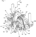
- Figure 1 shows a perspective view of a longitudinal sealing device 12 for a packaging machine.
- the longitudinal sealing device 12 comprises at least one sealing device 10.
- the longitudinal sealing device 12 comprises at least one further sealing device 60.
- the sealing device 10 and the further sealing device 60 are preferably constructed in a mirror-symmetrical manner.
- the sealing device 10 and the further sealing device 60 in particular comprise the same components.
- the components of the further sealing device 60 are only occasionally provided with reference symbols, the reference symbols of the further sealing device 60 having the same numbers as the reference symbols of the sealing device 10, the reference symbols being marked with an apostrophe to distinguish them.
- the sealing device 10 is intended for sealing a packaging material 50.
- the sealing device 10 comprises at least one packaging transport unit 48.
- the packaging transport unit 48 is provided for conveying the packaging material 50 along a transport direction 70 between sealing jaws 16, 20, in particular between the sealing device 10 and the further sealing device 60.
- the transport direction 70 is preferably aligned vertically during operation of the longitudinal sealing device 12 and points in particular from top to bottom.
- the packaging transport unit 48 is designed in particular mirror-symmetrically to a packaging transport unit 48' of the further sealing device 60, which, due to perspective, is in Figure 1 can be seen.
- the packaging transport unit 48 comprises at least one contact conveying element 62 for frictional and/or force-locking with the packaging material 50 (cf. contact conveying element 62' of the further sealing device 60).
- the packaging transport unit 48 comprises at least one guide element 64 (cf. guide element 64' of the further sealing device 60).
- the packaging transport unit 48 comprises at least one further guide element 66 (cf. further guide element 66' of the further sealing device 60).
- the guide elements 64, 66 are provided for guiding the contact conveying element 62 along the transport direction 70.
- the packaging transport unit 48 comprises a gear element 68 for transmitting force and/or torque to the contact conveying element 62 (cf. gear element 68' of the further sealing device 60).
- the gear element 68 is arranged at a distance from the guide element 64 and the further guide element 66 in a direction perpendicular to the transport direction 70.
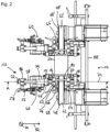
- Figure 2 shows a view of the longitudinal sealing device 12 opposite to the transport direction 70, in particular an underside of the longitudinal sealing device 12.
- the sealing device 10 comprises the sealing jaw 16.
- the sealing device 10 comprises the further sealing jaw 20.
- the sealing device 10 comprises at least one seal holder 14 for fixing the sealing jaw 16.
- the sealing device 10 comprises at least one further seal holder 18 for fixing the further sealing jaw 20.
- the seal holder 14 and the further seal holder 18 are mounted so as to be movable relative to one another.
- the sealing device 10 comprises a mechanical coupling unit 22.
- the seal holder 14 and the further seal holder 18 are arranged on the coupling unit 22.
- the coupling unit 22 comprises at least one force transmission element 24 (cf. Fig.3 ).
- the coupling unit 22 comprises at least one further force transmission element 26, 28, in particular two further force transmission elements 26, 28, one of which is referred to below as an additional force transmission element 28 if a distinction is necessary (cf. Fig.1 and 3 ).
- the force transmission element 24 is provided for transmitting a sealing force provided to the seal holder 14 in the form of a pressure force during sealing.
- the further force transmission elements 26, 28 are provided for transmitting the sealing force provided to the further seal holder 18 in the form of a tensile force during sealing.
- the sealing device 10 comprises at least one, in particular immovable, counter seal holder unit 52.
- the sealing device 10 comprises at least one, in particular immovable, further counter seal holder unit 54.
- the counter seal holder unit 52 forms a pressing surface for pressing on the sealing jaws 16.
- the further counter seal holder unit 54 forms a pressing surface for pressing on the further sealing jaws 20.
- the counter seal holder units 52, 54 comprise in particular a common Counter seal holder element 84, which forms the pressing surfaces of both counter seal holder units 52, 54.
- the counter seal holder unit 52 comprises in particular a counter seal holder and the further counter seal holder unit 54 preferably a further counter seal holder to which the common counter seal holder element 84 is fastened, in particular screwed.
- the contact conveying element 62 is at least partially arranged between the seal holders 14, 18.
- the contact conveying element 62 is arranged between the counter seal holder units 52, 54.
- the counter seal holder units 52, 54 are arranged together with the contact conveying element 62 between the seal holders 14, 18.
- the sealing jaw 16, the further sealing jaw 20 and the contact conveying element 62 are arranged at least substantially flush with respect to a plane perpendicular to the transport direction 70.
- the seal holders 14, 18 are in particular mounted in such a way that they can be displaced relative to one another along a displacement direction 82.
- the seal holder 14, the counter seal holder unit 52, the packaging transport unit 48, the further counter seal holder unit 54 and/or the further seal holder 18, in particular in this order, are arranged on the further force transmission elements 26, 28.
- An axis of rotation of the guide element 64 or of the further guide element 66 runs at least substantially parallel to the displacement direction 82 of the seal holder 14 and/or the further seal holder 18.
- Figure 3 shows a sectional view of the longitudinal sealing device 12 in a sealing plane 72.
- the sealing plane 72 runs in particular perpendicular to the transport direction 70.
- the coupling unit 22 comprises at least one, in particular pneumatic, piston unit 30 with at least one piston chamber 32 and with a piston 34 mounted in the piston chamber 32.
- the piston 34 is operatively connected to the force transmission element 24.
- the piston chamber 32 is operatively connected to the further force transmission elements 26, 28.
- the coupling unit 22 comprises at least one further piston unit 36 with a further piston 38.
- the further piston 38 is arranged along a mechanical chain of action in rows with the piston 34.
- the coupling unit 22 comprises at least one additional piston unit 40 with an additional piston 42.
- the additional piston 42 is arranged parallel to the further piston 38.
- the additional piston unit 40, the piston unit 30 and/or the further piston unit 36 are arranged on a common mounting plate 44 of the piston units 30, 36, 40.
- the sealing device 10 comprises in particular a structural unit as a deflection unit 86.
- the deflection unit 86 is in particular operatively connected to further pistons 38 and/or the additional piston 38.
- the deflection unit 86 is in particular fixed, in particular clamped, to the further force transmission elements 26, 28.
- the coupling unit 22 comprises at least one adjustment element 56, 58, with which a starting position of the seal holder 14 and/or the further seal holder 18 relative to the force transmission element 24 and/or the further force transmission elements 26, 28 and/or relative to the contact conveying element 62 can be adjusted without tools.
- the sealing device 10 comprises a bearing unit 46 for floatingly supporting the coupling unit 22.
- the bearing unit 46 is intended to absorb at least substantially the entire weight of the coupling unit 22 and the seal holder 14, 18.
- the further force transmission element 26, 28 is arranged so as to protrude through a material recess of the seal holder 14.
- the bearing unit 46 comprises a seal holder bearing element 74.
- the seal holder bearing element 74 is designed, for example, as a sliding bearing.
- the seal holder bearing element 74 is arranged in particular in the material recess of the seal holder 14.
- the further force transmission element 26 is mounted in particular in the seal holder bearing element 74.
- the further force transmission element 26, 28 is arranged so as to protrude through a material recess of the packaging transport unit 48.
- the bearing unit 46 comprises a transport bearing element 76.
- the transport bearing element 76 is designed, for example, as a sliding bearing.
- the transport bearing element 76 is arranged, in particular, in the material recess of the packaging transport unit 48.
- the further force transmission element 26 is arranged, in particular, in the transport bearing element 76.
- the further force transmission element 26, 28 is arranged so as to protrude through a material recess of the counter-seal holder unit 52, 54.
- the bearing unit 46 comprises a counter-seal holder bearing element 78.
- the counter-seal holder bearing element 78 is designed, for example, as a sliding bearing.
- the counter-seal holder bearing element 78 is arranged, in particular, in the material recess of the counter-seal holder unit 52.
- the further Force transmission element 26 is mounted in particular in the counter seal holder bearing element 78.
- the bearing unit 46 comprises a further counter seal holder bearing element 80.
- the further counter seal holder bearing element 80 is designed, for example, as a sliding bearing.
- the counter seal holder bearing element 80 is arranged in particular in the material recess of the further counter seal holder unit 54.
- the further force transmission element 26 is mounted in particular in the further counter seal holder bearing element 80.
- the counter seal holder bearing element 78 and/or the further counter seal holder bearing element 80 are arranged in particular within the transport bearing element 76.
- the counter seal holder unit 52 and/or the further counter seal holder unit 54 of the sealing device 10 is arranged, in particular fixed, on the bearing unit 46, in particular on the transport bearing element 76.
- the guide element 64 and/or the further guide element 66 of the packaging transport unit 48 for guiding the contact conveyor element 62 are arranged on the bearing unit 46.
- the guide element 64 is mounted in particular on the transport bearing element 76.
- the sealing jaw 16 is in particular fastened to the seal holder 14.
- the seal holder 14 is preferably fastened to the force transmission element 24.
- the seal holder 14 is in particular movably mounted on the further force transmission elements 26, 28, in particular for carrying out a linear movement.
- the force transmission element 24 is in particular fastened to the piston 34.
- the piston 34 is preferably mounted in the piston chamber 32.
- the piston chamber 32 is preferably fastened to the common mounting plate 44.
- a further piston chamber of the further piston unit 36 and/or an additional piston chamber of the additional piston unit 40 is in particular fastened to the common mounting plate 44.
- the further piston 38 is in particular mounted in the further piston chamber.
- the additional piston 42 is in particular mounted in the additional piston chamber.
- the further piston 38 and/or the additional piston are in particular fastened to the deflection unit 86.
- the further force transmission elements 26, 28 are preferably fastened to the deflection unit 86.
- the further force transmission elements 26, 28 are mounted in particular within the transport bearing element 76.
- the transport bearing element 76 is arranged, in particular fixed, directly or indirectly on a machine frame 88 of the longitudinal seam device 12.
- the further seal holder 20 is attached to the further force transmission elements 18.
- the further sealing jaw 20 is in particular attached to the further seal holder 20.
- the seal holders 16, 20 move in opposite directions perpendicular to the transport direction 70 via the force transmission elements 24, 26, 28 and in particular via the deflection unit 86.
- a maximum longitudinal extension of the contact conveying element 62 parallel to the transport direction 70 and a maximum longitudinal extension of the seal holder 14 and/or the further seal holder 18 parallel to the transport direction 70 are at least substantially the same length.
- a longitudinal axis of a mounting rod of the sealing device 10, on which the seal holder 14 and/or the further seal holder 18 are arranged, and an axis of rotation of the guide element 64 or the further guide element 66 are arranged at least substantially coaxially.
- the mounting rod is formed in particular by the further force transmission element 26.
Landscapes
- Engineering & Computer Science (AREA)
- Mechanical Engineering (AREA)
- Auxiliary Devices For And Details Of Packaging Control (AREA)
Description
- Aus
EP 1 167 192 A2 ,DE 10 2006 046 123 A1 undWO 2007/142114 A1 sind bereits Siegelvorrichtungen für eine Längssiegeleinrichtung einer Verpackungsmaschine bekannt, wobei die bereits bekannten Siegelvorrichtungen zumindest eine Siegelbacke und zumindest eine weitere Siegelbacke zu einem Versiegeln eines Verpackungsmaterials, zumindest einen Siegelhalter zu einem Fixieren der Siegelbacke und einen weiteren Siegelhalter zu einem Fixieren der weiteren Siegelbacke, wobei der Siegelhalter und der weitere Siegelhalter relativ zueinander beweglich gelagert sind, und zumindest eine Verpackungstransporteinheit zu einem Fördern eines Verpackungsmaterials entlang einer Transportrichtung zwischen den Siegelbacken hindurch umfassen, wobei die Verpackungstransporteinheit zumindest ein Kontaktförderelement zu einem Reib- und/oder Kraftschluss mit dem Verpackungsmaterial umfasst, wobei das Kontaktförderelement zumindest teilweise zwischen den Siegelhaltern angeordnet ist. - Die Erfindung geht aus von einer Siegelvorrichtung für eine Längssiegeleinrichtung einer Verpackungsmaschine, mit zumindest einer Siegelbacke und zumindest einer weiteren Siegelbacke zu einem Versiegeln eines Verpackungsmaterials, mit zumindest einem Siegelhalter zu einem Fixieren der Siegelbacke und einem weiteren Siegelhalter zu einem Fixieren der weiteren Siegelbacke, wobei der Siegelhalter und der weitere Siegelhalter relativ zueinander beweglich gelagert sind, und mit zumindest einer Verpackungstransporteinheit zu einem Fördern eines Verpackungsmaterials entlang einer Transportrichtung zwischen den Siegelbacken hindurch, wobei die Verpackungstransporteinheit zumindest ein Kontaktförderelement zu einem Reib- und/oder Kraftschluss mit dem Verpackungsmaterial umfasst, wobei das Kontaktförderelement zumindest teilweise zwischen den Siegelhaltern angeordnet ist.
- Es wird vorgeschlagen, dass die Siegelvorrichtung eine Montagestange umfasst, an welcher der Siegelhalter und/oder der weitere Siegelhalter angeordnet sind, wobei die Verpackungstransporteinheit ein, insbesondere das bereits genannte, Führungselement und ein weiteres, insbesondere das bereits genannte weitere, Führungselement zu einer Führung des Kontaktförderelements entlang der Transportrichtung umfasst, wobei eine Längsachse der Montagestange und eine, insbesondere die bereits genannte physische, Drehachse des Führungselements oder des weiteren Führungselements zumindest im Wesentlichen koaxial angeordnet sind. Das Kontaktförderelement ist insbesondere als geschlossenes Band ausgebildet. Die Verpackungstransporteinheit umfasst insbesondere zumindest das Führungselement, insbesondere mehrere Führungselemente, an welchem/n das Kontaktförderelement angeordnet ist. Insbesondere umspannt das Kontaktförderelement das zumindest eine Führungselement, insbesondere die Führungselemente, in einer zu der Transportrichtung parallelen Transporteinheitsebene. Das/Die Führungselement/e kann/können mit einem Maschinengestell der Siegelvorrichtung starr verbunden sein oder relativ zu dem Maschinengestell drehbar an dem Maschinengestell gelagert sein. Beispielsweise ist das Kontaktförderelement auf einer Innenseite als glattes Band oder als Zahnriemen ausgebildet. Die Innenseite ist insbesondere dem zumindest einen Führungselement zugewandt angeordnet. Optional ist eine Außenseite des Kontaktförderelements strukturiert ausgebildet. Die Außenseite ist insbesondere dazu vorgesehen, während eines Betriebs der Längssiegeleinrichtung in direktem Kontakt mit dem Verpackungsmaterial zu stehen. Die Außenseite umfasst beispielsweise Vertiefungen zu einem Anhaften des Verpackungsmaterials an der Außenseite, aufgrund eines entstehenden Unterdrucks in der Vertiefung. Beispielsweise ist das zumindest eine Führungselement als Führungsrolle, insbesondere Umlenkrolle, als Stift, als Bolzen oder dergleichen, ausgebildet. Das Kontaktförderelement umspannt in der zur Transportrichtung parallelen Transporteinheitsebene insbesondere eine Innenfläche. Insbesondere ist das zumindest eine Führungselement innerhalb der Innenfläche angeordnet. Optional umfasst die Verpackungstransporteinheit zumindest ein Strukturelement, insbesondere eine Transporteinheitmontageplatte, welches zusammen mit dem zumindest einen Führungselement die Innenfläche zumindest im Wesentlichen, insbesondere zumindest zu 25 %, bevorzugt zu mehr als 50 %, bezogen auf einen Gesamtflächeninhalt der Innenfläche ausfüllt.
- Bei dem Siegeln wird insbesondere das Verpackungsmaterial durch Anpressen zumindest einer der Siegelbacken an das Verpackungsmaterial mit der Siegelkraft gesiegelt. Die Siegelbacke ist zumindest während des Siegelns insbesondere starr mit dem Siegelhalter verbunden, insbesondere daran fixiert. Vorzugsweise ist die weitere Siegelbacke zumindest während des Siegelns starr mit dem weiteren Siegelhalter verbunden, insbesondere daran fixiert. Insbesondere werden die Siegelbacken während des Siegelns vermittelt über die Siegelhalter mit einer Siegelkraft gegen das Verpackungsmaterial gepresst. Bevorzugt ist die Siegelbacke zur Erzeugung einer Längsnaht an dem Verpackungsmaterial vorgesehen. Bevorzugt ist die weitere Siegelbacke zur Erzeugung einer weiteren Längsnaht an dem Verpackungsmaterial vorgesehen. Die Längsnaht und die weitere Längsnaht können als Kantennaht, welche insbesondere aus zwei benachbarten Bereichen des Verpackungsmaterials eine Kante einer Verpackung bildet, oder als Verschlussnaht, welche insbesondere zwei voneinander abgewandte Enden des Verpackungsmaterials oder zwei Bahnen des Verpackungsmaterials miteinander verbindet, ausgebildet sein. Die Längsnaht und die weitere Längsnaht werden vorzugsweise beabstandet voneinander hergestellt. Insbesondere sind die Siegelbacke und die weitere Siegelbacke während des Siegelns beabstandet voneinander angeordnet. Die Siegelbacke und die weitere Siegelbacke sind vorzugsweise elektrisch aufheizbar ausgebildet, um die Längsnähte zu erzeugen. Alternativ sind die Siegelbacke und die weitere Siegelbacke zu einem Erstellen der Längsnähte mittels Ultraschallschweißen ausgebildet. Die Siegelbacken sind vorzugsweise an dem Siegelhaltern verschraubt oder anderweitig fixiert. Insbesondere sind die Siegelbacken, beispielsweise abhängig von der zu erstellenden Längsnaht und/oder der Art des Verpackungsmaterials, austauschbar.
- Die Siegelbacken werden zu einem Siegeln, jeweils einzeln oder in einer gekoppelten Bewegung, insbesondere entlang einer Verschieberichtung aufeinander zubewegt. Die Verschieberichtung der Siegelbacken verläuft vorzugsweise zumindest im Wesentlichen senkrecht zu der Transportrichtung des Verpackungsmaterials und insbesondere senkrecht zu der Transporteinheitsebene. Insbesondere liegen der Siegelhalter, der weitere Siegelhalter und die Verpackungstransporteinheit, insbesondere das Kontaktförderelement, in einer Siegelebene, welche parallel zu der Transportrichtung und der Verschieberichtung verläuft, und insbesondere in mehreren Querschnittsebenen, welche senkrecht zu der Transportrichtung verlaufen und insbesondere senkrecht zu der Transporteinheitsebene und der der Siegelebene verlaufen. Insbesondere sind die Siegelhalter derart gelagert, dass sie sich zu einem Siegeln auf das Kontaktförderelement zu bewegen können und insbesondere nach einem Siegeln von dem Kontaktförderelement weg bewegen können. Insbesondere ist das Kontaktförderelement zwischen den Siegelhaltern hindurch ragend angeordnet. Der Ausdruck "im Wesentlichen senkrecht" soll hier insbesondere eine Ausrichtung einer Richtung relativ zu einer Bezugsrichtung definieren, wobei die Richtung und die Bezugsrichtung, insbesondere in einer Projektionsebene betrachtet, einen Winkel von 90° einschließen und der Winkel eine maximale Abweichung von insbesondere kleiner als 8°, vorteilhaft kleiner als 5° und besonders vorteilhaft kleiner als 2° aufweist. Unter "im Wesentlichen parallel" soll hier insbesondere eine Ausrichtung einer Richtung relativ zu einer Bezugsrichtung, insbesondere in einer Ebene, verstanden werden, wobei die Richtung gegenüber der Bezugsrichtung eine Abweichung insbesondere kleiner als 8°, vorteilhaft kleiner als 5° und besonders vorteilhaft kleiner als 2° aufweist.
- Das Verpackungsmaterial ist vorzugsweise folienförmig ausgebildet und kann insbesondere einschichtig oder mehrschichtig aufgebaut sein. Das Verpackungsmaterial und/oder zumindest eine Schicht des Verpackungsmaterials kann aus Papier, einem Kunststoff, insbesondere Polypropylen, Polyester und/oder Polyethylene, einem Textil und/oder einem Metall gefertigt sein. Insbesondere ist das Verpackungsmaterial ein Verbundstoff. Die Verpackungsmaschine ist insbesondere dazu vorgesehen, aus dem Verpackungsmaterial einen Behälter, insbesondere einen Schlauchbeutel und/oder einen Standbodenbeutel, zu formen, mit einem Packgut zu befüllen und zu verschließen. Vorzugsweise umfasst die Verpackungsmaschine zumindest ein Füllrohr oder einen Füllschacht zu einem Befüllen der aus dem Verpackungsmaterial geformten Behälter. Das Füllrohr oder der Füllschacht weist vorzugsweise eine Befüllungslängsachse auf, welche dazu vorgesehen ist, zu einem Betrieb der Verpackungsmaschine an der Vertikalen ausgerichtet zu werden und entlang derer ein Packgut bei einem Betrieb der Verpackungsmaschine in den geformten Behälter transportiert wird. Die Verpackungsmaschine umfasst insbesondere eine Verpackungsmaterialführung, welche dazu vorgesehen ist, das Verpackungsmaterial, bevorzugt eine einzelne Bahn des Verpackungsmaterials, schlauchförmig um das Füllrohr oder den Füllschacht herum zu formen. Die Längssiegeleinrichtung ist insbesondere dazu vorgesehen, durch das Siegeln eine den Füllschacht umgreifende Form des Verpackungsmaterials zu fixieren. Insbesondere ist die Längssiegeleinrichtung dazu vorgesehen, die Längsnähte zumindest im Wesentlichen parallel zu der Befüllungslängsachse zu erstellen. Insbesondere ist die Transportrichtung dazu vorgesehen, zu einem Betrieb der Längsnahteinrichtung koaxial mit Befüllungslängsachse angeordnet zu werden.
- Durch die erfindungsgemäße Ausgestaltung kann eine vorteilhaft kompakte Siegelvorrichtung zur Verfügung gestellt werden. Insbesondere kann ein Siegeln mittels der Siegelbacken und ein Transport des Verpackungsmaterials in einem gemeinsamen Bauraum durchgeführt werden. Insbesondere kann eine maximale Längserstreckung der Siegelvorrichtung entlang der Transportrichtung vorteilhaft klein gehalten halten werden, insbesondere bei Beibehaltung oder Reduzierung einer Fallhöhe des Behälters nach einem Verlassen der Längssiegeleinrichtung.
- Ferner wird vorgeschlagen, dass die Siegelvorrichtung zumindest eine Gegensiegelhaltereinheit, welche eine Aufpressfläche zu einem Aufpressen eine der Siegelbacken ausbildet, und eine Lagereinheit umfasst, an welcher die Gegensiegeleinheit und ein, insbesondere das bereits genannte, Führungselement der Verpackungstransporteinheit zu einer Führung des Kontaktförderelements angeordnet sind. Die Gegensiegelhaltereinheit umfasst vorzugsweise einen Gegensiegelhalter zu einer Fixierung der Gegensiegelhaltereinheit relativ zu dem Maschinengestell und ein Gegensiegelelement, welches die Aufpressfläche ausbildet. Das Gegensiegelelement ist vorzugsweise an dem Gegensiegelhalter angeordnet, insbesondere starr mit dem Gegensiegelhalter verbunden, oder mit diesem einteilig ausgebildet. Die Aufpressfläche ist entlang der Verschieberichtung dem Siegelhalter gegenüberliegend angeordnet. Insbesondere presst der Siegelhalter die Siegelbacke während des Siegelns gegen die Aufpressfläche, wobei zwischen der Siegelbacke und der Aufpressfläche das Verpackungsmaterial angeordnet ist. Die Gegensiegelhaltereinheit ist zumindest während des Siegelns relativ zu dem Maschinengestell unbeweglich, zumindest bis zu einer vorgesehenen maximal einstellbaren Siegelkraft der Siegelvorrichtung. Vorzugsweise umfasst die Siegelvorrichtung eine analog ausgebildete weitere Gegensiegelhaltereinheit, welche eine weitere Aufpressfläche ausbildet, welche dem weiteren Siegelhalter entlang der Verschieberichtung gegenüberliegend angeordnet ist. Insbesondere umfasst die Lagereinheit zumindest ein Transportlagerelement, mittels dessen das zumindest eine Führungselement, insbesondere drehbar, gelagert ist. Das Transportlagerelement ist insbesondere als physische Drehachse ausgebildet, wobei das Führungselement insbesondere relativ zu dem Transportlagerelement drehbar ist und das Transportlagerelement insbesondere unbeweglich relativ zu dem Maschinengestell angeordnet ist. Vorzugsweise ist die Gegensiegelhaltereinheit und/oder die weitere Gegensiegelhaltereinheit zerstörungsfrei lösbar an der Lagereinheit, insbesondere dem Transportlagerelement, fixiert, insbesondere geklemmt. Insbesondere ist die Gegensiegelhaltereinheit und/oder die weitere Gegensiegeleinheit in einem Ruhezustand der Längssiegeleinrichtung entlang der Lagereinheit verschiebbar, um einen Formatwechsel des herzustellenden Behälters durchzuführen. Insbesondere ist das Führungselement in der Siegelebene zwischen der Gegensiegelhaltereinheit und der weiteren Gegensiegelhaltereinheit angeordnet. Insbesondere sind die Gegensiegelhaltereinheiten zusammen mit dem Führungselement entlang der Verschieberichtung zwischen den Siegelhaltern angeordnet. Eine gedachte Drehachse des zumindest einen Führungselements liegt vorzugswiese in der Siegelebene und verläuft insbesondere senkrecht zu der Transporteinheitsebene. Das Gegensiegelelement der Gegensiegelhaltereinheit und ein Gegensiegelelement der weiteren Gegensiegelhaltereinheit können separat voneinander ausgebildet sein oder einteilig ausgebildet sein. Insbesondere können das Gegensiegelelement der Gegensiegelhaltereinheit und das Gegensiegelelement der weiteren Gegensiegelhaltereinheit in einer Richtung senkrecht zur Transportrichtung, insbesondere zu einer Formatanpassung eines herzustellenden Behälters, unabhängig voneinander verschoben werden oder nur gemeinsam verschoben werden. Durch die erfindungsgemäße Ausgestaltung kann die Verpackungstransporteinheit vorteilhaft eine Halterung der Siegelvorrichtung zu einer Fixierung der Gegensiegelhaltereinheit an dem Maschinengestell ausbilden. Insbesondere kann auf eine eigenständige Halterung für die Gegensiegelhaltereinheit verzichtet werden. Insbesondere kann eine vorteilhaft bauteilarme Siegelvorrichtung zur Verfügung gestellt werden.
- Ferner wird vorgeschlagen, dass eine zu der Transportrichtung parallele maximale Längserstreckung des Kontaktförderelements und eine zu der Transportrichtung parallele maximale Längserstreckung des Siegelhalters und/oder des weiteren Siegelhalters zumindest im Wesentlichen gleich lang ausgebildet sind. Vorzugsweise umfasst die Verpackungstransporteinheit zumindest ein weiteres Führungselement, welches insbesondere baugleich zu dem Führungselement ausgebildet ist. Eine gedachte Drehachse des weiteren Führungselements liegt vorzugsweise in der Siegelebene. Ein Abschnitt der Außenseite des Kontaktförderelements, welches sich von dem Führungselement zu dem weiteren Führungselement erstreckt, ist insbesondere zumindest im Wesentlichen parallel zu der Siegelebene angeordnet. Insbesondere ist die maximale Längserstreckung des Kontaktförderelements parallel zur Transportrichtung gegeben durch einen Abstand der gedachten Drehachsen des Führungselements und des weiteren Führungselements zuzüglich eines Führungsradius der Führungselemente zuzüglich einer Materialstärke des Kontaktförderelements. Die Materialstärke des Kontaktförderelements verläuft insbesondere senkrecht zu der Außenseite und/oder der Innenseite des Kontaktförderelements. Eine maximale Längserstreckung der Siegelhalter parallel zur Transportrichtung ist insbesondere zumindest im Wesentlichen gleich lang wie eine maximale Längserstreckung der Siegelbacken parallel zur Transportrichtung. Insbesondere sind die Siegelbacken an zumindest zwei Fixierpunkten des jeweiligen Siegelhalters fixiert, insbesondere angeschraubt, welche insbesondere an gegenüberliegenden Enden der Siegelbacken angeordnet sind. Unter "im Wesentlich gleich lang" soll insbesondere gleich lang bis auf eine Abweichung von weniger als 50 %, bevorzugt weniger als 33 %, besonderes bevorzugt weniger als 25 %, voneinander verstanden werden. Insbesondere sind die Siegelhalter, die Siegelbacken und das Kontaktförderelement vollständig zwischen einer zu der Transportrichtung senkrechten Eingabeebene und einer zu der Transportrichtung senkrechten Ausgabeebene angeordnet, wobei die Eingabeebene und die Ausgabeebene weniger als 200 %, insbesondere weniger als 150 %, der maximalen Längserstreckung der Siegelhalter oder des Kontaktförderelements aufweist. Optional ist das Kontaktförderelement relativ zu dem Siegelhaltern entgegen der Transportrichtung oder entlang der Transportrichtung geringfügig versetzt angeordnet. Unter "geringfügig" soll insbesondere um weniger als 25 %, bevorzugt um weniger als 10 %, der maximalen Längserstreckung der Siegelhalter und/oder des Kontaktförderelements parallel zu der Transportrichtung verstanden werden. Durch die erfindungsgemäße Ausgestaltung kann ein vorteilhaft zuverlässiger Kontakt zwischen der Verpackungstransporteinheit und dem Verpackungsmaterial erreicht werden, insbesondere bei einer vorteilhaft geringen maximale Längserstreckung der Siegelvorrichtung parallel zu der Transportrichtung
- Darüber hinaus wird vorgeschlagen, dass die Verpackungstransporteinheit zumindest ein, insbesondere das bereits genannte, Führungselement und ein weiteres, insbesondere das bereits genannte weitere, Führungselement zu einer Führung des Kontaktförderelements entlang der Transportrichtung sowie ein von dem Führungselement und dem weiteren Führungselement in einer zur Transportrichtung senkrechten Richtung beabstandet angeordnetes Getriebeelement zu einer Kraft- und/oder Drehmomentübertragung auf das Kontaktförderelement umfasst. Das Getriebeelement ist zumindest im Wesentlichen baugleich mit dem Führungselement ausgebildet, wobei das Getriebeelement an einer Antriebswelle eines Motors der Verpackungstransporteinheit angeschlossen, insbesondere starr mit der Antriebswelle des Motors verbunden, ist. Eine gedachte Drehachse des Getriebeelements verläuft insbesondere zumindest im Wesentlichen parallel zu der Transporteinheitsebene. Vorzugsweise umspannt das Kontaktförderelement in der Transporteinheitsebene das Führungselement, das weitere Führungselement und das Getriebeelement. Vorzugsweise ist das Getriebeelement, insbesondere der Motor, zu einem Umwälzen des Kontaktförderelements in der Transporteinheitsebene vorgesehen. Insbesondere ist das Getriebeelement, insbesondere der Motor, zu einem Antrieb eines dem Verpackungsmaterial zugewandten Abschnitts des Kontaktförderelements entlang der Transportrichtung vorgesehen. Die von dem Kontaktförderelement in der Transporteinheitsebene umspannte Innenfläche ist insbesondere zumindest im Wesentlichen dreieckförmig oder polygonförmig ausgebildet, wobei in jedem, insbesondere abgerundeten, Eck der Innenfläche insbesondere eines der Führungselemente oder das Getriebeelement angeordnet ist. Die in der Siegelebene angeordneten Führungselemente sind vorzugsweise antriebslos ausgebildet. Vorzugsweise rotieren die Führungselemente, insbesondere nur, durch eine Kraft- und/oder Drehmomentübertragung durch das mittels des Getriebeelements angetriebene Kontaktförderelement. Durch die erfindungsgemäße Ausgestaltung kann der Motor der Verpackungstransporteinheit vorteilhaft weit entfernt von den Siegelhaltern angeordnet werden.
- Die Montagestange weist entlang der Längsachse insbesondere ihre größte Erstreckung auf. Die Längsachse verläuft vorzugsweise zumindest im Wesentlichen parallel zu der Verschieberichtung. Die Montagestange kann als Kraftübertragungselement ausgebildet sein, um eine Verschiebung zumindest eines der Siegelhalter zu veranlassen oder als Lagerstange, entlang welcher zumindest einer der Siegelhalter beweglich gelagert ist. Besonders bevorzugt ist die physische Drehachse des Führungselements als Hohlachse ausgebildet. Insbesondere ist eine Außenwand der physischen Drehachse insbesondere zu einer Lagerung des Führungselements ausgebildet. Die Montagestange ist insbesondere in einem Innenraum der physischen Drehachse angeordnet. Die physische Drehachse kann an der Montagestange fixiert sein oder die Montagestange, insbesondere zu einer geradlinigen Bewegung der Montagestange durch die physische Drehachse hindurch, lagern. Vorzugsweise umfasst die Siegelvorrichtung eine weitere Montagestange, welche in analoger Weise koaxial mit einer physischen Drehachse des weiteren Führungselements angeordnet ist. Insbesondere sind die Montagestangen an voneinander abgewandten Enden der Siegehalter an den Siegelhaltern angeordnet. Durch die erfindungsgemäße Ausgestaltung kann die Verpackungstransporteinheit vorteilhaft eine Halterung der Siegelvorrichtung zu einer Lagerung der Siegelhalter an dem Maschinengestell ausbilden. Insbesondere kann auf eine eigenständige Halterung für die Siegelhalter verzichtet werden. Insbesondere kann eine vorteilhaft bauteilarme Siegelvorrichtung zur Verfügung gestellt werden.
- Weiterhin wird vorgeschlagen, dass die Verpackungstransporteinheit ein, insbesondere das bereits genannte, Führungselement und ein weiteres, insbesondere das bereits genannte weitere, Führungselement zu einer Führung des Kontaktförderelements entlang der Transportrichtung umfasst, wobei eine, insbesondere die bereits genannte gedachte, Drehachse des Führungselements oder des weiteren Führungselements zumindest im Wesentlichen parallel zu einer, insbesondere der bereits genannten, Verschieberichtung des Siegelhalters und/oder des weiteren Siegelhalters verläuft. Vorzugsweise liegt die Drehachse des Führungselements und die Drehachse des weiteren Führungselements in der Siegelebene. Durch die erfindungsgemäße Ausgestaltung können Komponenten der Verpackungstransporteinheit und Komponenten zur Halterung und/oder Lagerung der Siegelbacken vorteilhaft gemeinsam genutzt werden, insbesondere zur gegenseitigen Stabilisierung und/oder zur Einsparung von Bauteilen.
- Weiter wird vorgeschlagen, dass die Siegelbacke, die weitere Siegelbacke und das Kontaktförderelement bezüglich einer zur Transportrichtung senkrechten Ebene, im Weiteren Kontaktebene genannt, zumindest im Wesentlichen bündig angeordnet sind. Die Kontaktebene verläuft insbesondere zumindest im Wesentlichen parallel zu der Siegelebene. Die Siegelbacke umfasst insbesondere eine Siegelfläche, die zu einer Erzeugung der Längsnaht vorgesehen ist und insbesondere einer Siegelfläche der weiteren Siegelbacke zugewandt angeordnet ist. Die Siegelfläche wird insbesondere von einer Siegelkante und einer weiteren Siegelkante begrenzt, die jeweils zumindest im Wesentlichen parallel zu der Siegelebene und der Kontaktebene verlaufen. Vorzugsweise ist die Siegelkante weiter von der Siegelebene entfernt als die weitere Siegelkante. Besonders bevorzugt ist die Siegelkante der Siegelbacke, die Außenseite des Kontaktförderelements und eine analoge Siegelkante der weiteren Siegelbacke bezüglich der Kontaktebene zumindest im Wesentlichen bündig angeordnet. Vorzugsweise ist die Siegelkante der Siegelbacke in der Kontaktebene angeordnet. Vorzugsweise ist die Siegelkante der weiteren Siegelbacke bis auf eine Fertigungstoleranz in der Kontaktebene angeordnet. Die Außenseite des Kontaktförderelements ragt optional über die Kontaktebene hinaus, insbesondere in eine von der Siegelebene wegweisende Richtung, insbesondere um einen ausreichenden Kontakt mit dem Verpackungsmaterial sicherzustellen. Vorzugsweise ragt die Außenseite des Kontaktförderelements um weniger als 1 cm, bevorzugt um weniger als 5 mm, insbesondere um weniger als 1 mm über die Kontaktebene hinaus. Durch die erfindungsgemäße Ausgestaltung kann ein Transport mittels der Transporteinheit und ein Siegeln mittels der Siegelbacken innerhalb des gleichen Bauraums vorteilhaft zuverlässig durchgeführt werden.
- Ferner wird vorgeschlagen, dass die Siegelvorrichtung zumindest ein Verstellelement umfasst, mittels dessen eine Ausgangsposition des Siegelhalters und/oder des weiteren Siegelhalters relativ zu dem Kontaktförderelement werkzeuglos verstellbar ist. Das Verstellelement ist vorzugsweise zerstörungsfrei lösbar an der Montagestange angeordnet. Insbesondere umfasst die Siegelvorrichtung eine Struktureinheit, mit welcher zumindest einer der Siegelhalter, insbesondere starr, verbunden ist. Die Verpackungstransporteinheit ist in Verschieberichtung vorzugsweise unbeweglich relativ zu der Montagestange. Die Struktureinheit umfasst zwei gegenüberliegende Vorsprünge, welche gemeinsam die Montagestange umgreifen. Das Verstellelement ist insbesondere als Gewindefahrwerk ausgebildet, welches zu einem Einklemmen oder Lösen der Montagestange mittels der Vorsprünge vorgesehen ist. Alternativ umfasst die Montagestange ein Lochraster, durch welches ein als Stift oder als Schraube ausgebildetes Verstellelement hindurch an der Struktureinheit fixiert werden kann. Die Struktureinheit umfasst vorzugsweise zwei weitere Vorsprünge, welche die weitere Montagestange in analoger Weise umgreifen und welche von einem weiteren Verstellelement der Siegelvorrichtung fixiert oder gelöst werden können. Durch die erfindungsgemäße Ausgestaltung der Siegelvorrichtung kann die Siegelvorrichtung vorteilhaft einfach an unterschiedliche Formate herzustellende Behälter angepasst werden.
- Darüber hinaus wird eine Längssiegeleinrichtung mit zumindest einer erfindungsgemäßen Siegelvorrichtung und mit zumindest einer erfindungsgemäßen weiteren Siegelvorrichtung vorgeschlagen. Die weitere Siegelvorrichtung ist vorzugsweise zumindest im Wesentlichen baugleich zu der Siegelvorrichtung ausgebildet. Insbesondere umfasst die weitere Siegelvorrichtung einen Siegelhalter, einen weiteren Siegelhalter und/oder eine Verpackungstransporteinheit in analoger Weise wie für die Siegelvorrichtung beschrieben. Die Längssiegeleinrichtung weist vorzugsweise das Maschinengestell als einziges Maschinengestell auf, an welchem die Siegelvorrichtung und die weitere Siegelvorrichtung, beispielsweise schwimmend, gelagert sind. Alternativ umfasst die Siegelvorrichtung und die weitere Siegelvorrichtung je ein eigenes Maschinengestell. Die Komponenten der Siegelvorrichtung und der weiteren Siegelvorrichtung sind vorzugsweise spiegelsymmetrisch angeordnet, insbesondere zu einer zu der Verschieberichtung und der Transportrichtung parallelen Spiegelebene. Die Siegelvorrichtung und die weitere Siegelvorrichtung sind insbesondere beabstandet voneinander angeordnet oder nur über das gemeinsame Maschinengestell und/oder über gemeinsame hydraulische, elektrische oder pneumatische Zuleitungen miteinander verbunden. Durch die erfindungsgemäße Ausgestaltung kann eine vorteilhaft kompakte Längssicheleinrichtung bereitgestellt werden.
- Die erfindungsgemäße Siegelvorrichtung und/oder die erfindungsgemäße Längssiegeleinrichtung sollen/soll hierbei nicht auf die oben beschriebene Anwendung und Ausführungsform beschränkt sein. Insbesondere können/kann die erfindungsgemäße Siegelvorrichtung und/oder die erfindungsgemäße Längssiegeleinrichtung zu einer Erfüllung einer hierin beschriebenen Funktionsweise eine von einer hierin genannten Anzahl von einzelnen Elementen, Bauteilen und Einheiten abweichende Anzahl aufweisen. Zudem sollen bei den in dieser Offenbarung angegebenen Wertebereichen auch innerhalb der genannten Grenzen liegende Werte als offenbart und als beliebig einsetzbar gelten.
- Weitere Vorteile ergeben sich aus der folgenden Zeichnungsbeschreibung. In den Zeichnungen ist ein Ausführungsbeispiel der Erfindung dargestellt. Die Zeichnungen, die Beschreibung und die Ansprüche enthalten zahlreiche Merkmale in Kombination. Der Fachmann wird die Merkmale zweckmäßigerweise auch einzeln betrachten und zu sinnvollen weiteren Kombinationen zusammenfassen.
- Es zeigen:
- Fig. 1
- eine schematische Perspektivdarstellung einer erfindungsgemäßen Längssiegeleinrichtung mit einer erfindungsgemäßen Siegelvorrichtung und einer weiteren erfindungsgemäßen Siegelvorrichtung,
- Fig. 2
- eine schematische Darstellung der erfindungsgemäßen Längssiegeleinrichtung bei einem Blick entgegen einer Transportrichtung der erfindungsgemäßen Längssiegeleinrichtung und
- Fig. 3
- eine schematische Schnittdarstellung der erfindungsgemäßen Längssiegeleinrichtung in einer zu der Transportrichtung parallelen Schnittebene.
-
Figur 1 zeigt eine Perspektivdarstellung einer Längssiegeleinrichtung 12 für eine Verpackungsmaschine. Die Längssiegeleinrichtung 12 umfasst zumindest eine Siegelvorrichtung 10. Die Längssiegeleinrichtung 12 umfasst zumindest eine weitere Siegelvorrichtung 60. Die Siegelvorrichtung 10 und die weitere Siegelvorrichtung 60 sind vorzugsweise spiegelsymmetrisch aufgebaut. Die Siegelvorrichtung 10 und die weitere Siegelvorrichtung 60 umfassen insbesondere die gleichen Bauteile. Die Bauteile der weitere Siegelvorrichtung 60 sind der Übersichtlichkeit halber nur vereinzelt mit Bezugszeichen versehen, wobei die Bezugszeichen der weiteren Siegelvorrichtung 60 die gleichen Nummern wie die Bezugszeichen der Siegelvorrichtung 10 tragen, wobei die Bezugszeichen zu einer Unterscheidung mit einem Apostroph gekennzeichnet sind. Die Siegelvorrichtung 10 ist zu einem Versiegeln eines Verpackungsmaterials 50 vorgesehen. Die Siegelvorrichtung 10 umfasst zumindest einer Verpackungstransporteinheit 48. Die Verpackungstransporteinheit 48 ist zu einem Fördern des Verpackungsmaterials 50 entlang einer Transportrichtung 70 zwischen Siegelbacken 16, 20 hindurch vorgesehen, insbesondere zwischen der Siegelvorrichtung 10 und der weiteren Siegelvorrichtung 60 hindurch. Die Transportrichtung 70 ist während eines Betriebs der Längssiegeleinrichtung 12 vorzugsweise an der Vertikalen ausgerichtet und zeigt insbesondere von oben nach unten. - Die Verpackungstransporteinheit 48 ist insbesondere spiegelsymmetrisch zu einer Verpackungstransporteinheit 48' der weiteren Siegelvorrichtung 60 ausgebildet, welche perspektivbedingt in
Figur 1 zu sehen ist. Die Verpackungstransporteinheit 48 umfasst zumindest ein Kontaktförderelement 62 zu einem Reib- und/oder Kraftschluss mit dem Verpackungsmaterial 50 (vgl. Kontaktförderelement 62' der weiteren Siegelvorrichtung 60). Die Verpackungstransporteinheit 48 umfasst zumindest ein Führungselement 64 (vgl. Führungselement 64' der weiteren Siegelvorrichtung 60). Die Verpackungstransporteinheit 48 umfasst zumindest ein weiteres Führungselement 66 (vgl. weiteres Führungselement 66' der weiteren Siegelvorrichtung 60). Die Führungselemente 64, 66 sind zu einer Führung des Kontaktförderelements 62 entlang der Transportrichtung 70 vorgesehen. Die Verpackungstransporteinheit 48 umfasst ein Getriebeelement 68 zu einer Kraft- und/oder Drehmomentübertragung auf das Kontaktförderelement 62 (vgl. Getriebeelement 68' der weiteren Siegelvorrichtung 60). Das Getriebeelement 68 ist von dem Führungselement 64 und dem weiteren Führungselement 66 in einer zur Transportrichtung 70 senkrechten Richtung beabstandet angeordnet. -
Figur 2 zeigt eine Ansicht der Längssiegeleinrichtung 12 entgegen der Transportrichtung 70, insbesondere eine Unterseite der Längssiegeleinrichtung 12. Die Siegelvorrichtung 10 umfasst die Siegelbacke 16. Die Siegelvorrichtung 10 umfasst die weitere Siegelbacke 20. Die Siegelvorrichtung 10 umfasst zumindest einen Siegelhalter 14 zum Fixieren der Siegelbacke 16. Die Siegelvorrichtung 10 umfasst zumindest einen weiteren Siegelhalter 18 zum Fixieren der weiteren Siegelbacke 20. Der Siegelhalter 14 und der weitere Siegelhalter 18 sind relativ zueinander beweglich gelagert. Die Siegelvorrichtung 10 umfasst eine mechanische Kopplungseinheit 22. Der Siegelhalter 14 und der weitere Siegelhalter 18 sind an der Kopplungseinheit 22 angeordnet. Die Kopplungseinheit 22 umfasst zumindest ein Kraftübertragungselement 24 (vgl.Fig. 3 ). Die Kopplungseinheit 22 umfasst zumindest ein weiteres Kraftübertragungselement 26, 28, insbesondere zwei weitere Kraftübertragungselemente 26, 28, wobei eines davon im Weiteren als zusätzliches Kraftübertragungselement 28 bezeichnet wird, sofern eine Unterscheidung notwendig ist (vgl.Fig. 1 und3 ). Das Kraftübertragungselement 24 ist bei einem Siegeln zu einer Übertragung einer bereitgestellten Siegelkraft auf den Siegelhalter 14 in Form einer Druckkraft vorgesehen. Die weiteren Kraftübertragungselemente 26, 28 sind beim Siegeln zu einem Übertragen der bereitgestellten Siegelkraft auf den weiteren Siegelhalter 18 in Form einer Zugkraft vorgesehen. Die Siegelvorrichtung 10 umfasst zumindest eine, insbesondere unbewegliche, Gegensiegelhaltereinheit 52. Die Siegelvorrichtung 10 umfasst zumindest eine, insbesondere unbewegliche, weitere Gegensiegelhaltereinheit 54. Die Gegensiegelhaltereinheit 52 bildet eine Aufpressfläche zu einem Aufpressen der Siegelbacken 16 aus. Die weitere Gegensiegelhaltereinheit 54 bildet eine Aufpressfläche zu einem Aufpressen der weiteren Siegelbacken 20 aus. Die Gegensiegelhaltereinheiten 52, 54 umfassen insbesondere ein gemeinsames Gegensiegelhalterelement 84, welches die Aufpressflächen beider Gegensiegelhaltereinheiten 52, 54 ausbildet. Die Gegensiegelhaltereinheit 52 umfasst insbesondere einen Gegensiegelhalter und die weitere Gegensiegelhaltereinheit 54 vorzugsweise einen weiteren Gegensiegelhalter, an den das gemeinsame Gegensiegelhalterelement 84 befestigt, insbesondere verschraubt, ist. - Das Kontaktförderelement 62 ist zumindest teilweise zwischen den Siegelhaltern 14, 18 angeordnet. Insbesondere ist das Kontaktförderelement 62 zwischen den Gegensiegelhaltereinheiten 52, 54 angeordnet. Insbesondere sind die Gegensiegelhaltereinheiten 52, 54 zusammen mit dem Kontaktförderelement 62 zwischen den Siegelhaltern 14, 18 angeordnet. Die Siegelbacke 16, die weitere Siegelbacke 20 und das Kontaktförderelement 62 sind bezüglich einer zur Transportrichtung 70 senkrechten Ebene zumindest im Wesentlichen bündig angeordnet. Die Siegelhalter 14, 18 sind insbesondere derart gelagert, dass sie entlang einer Verschieberichtung 82 gegeneinander verschiebbar sind. Vorzugsweise ist der Siegelhalter 14, die Gegensiegelhaltereinheit 52, die Verpackungstransporteinheit 48, die weitere Gegensiegelhaltereinheit 54 und/oder der weitere Siegelhalter 18, insbesondere in dieser Reihenfolge, an den weiteren Kraftübertragungselementen 26, 28 angeordnet. Eine Drehachse des Führungselements 64 oder des weiteren Führungselements 66 verläuft zumindest im Wesentlichen parallel zu der Verschieberichtung 82 des Siegelhalters 14 und/oder des weiteren Siegelhalters 18.
-
Figur 3 zeigt eine Schnittdarstellung der Längssiegeleinrichtung 12 in einer Siegelebene 72. Die Siegelebene 72 verläuft insbesondere senkrecht zu der Transportrichtung 70. Die Kopplungseinheit 22 umfasst zumindest eine, insbesondere pneumatische, Kolbeneinheit 30 mit zumindest einer Kolbenkammer 32 und mit einem in der Kolbenkammer 32 gelagerten Kolben 34. Der Kolben 34 ist mit dem Kraftübertragungselement 24 wirkverbunden. Die Kolbenkammer 32 ist mit den weiteren Kraftübertragungselementen 26, 28 wirkverbunden. Die Kopplungseinheit 22 umfasst zumindest eine weitere Kolbeneinheit 36 mit einem weiteren Kolben 38. Der weitere Kolben 38 ist entlang einer mechanischen Wirkkette in Reihen mit dem Kolben 34 angeordnet. Die Kopplungseinheit 22 umfasst zumindest eine zusätzliche Kolbeneinheit 40 mit einem zusätzlichen Kolben 42. Der zusätzliche Kolben 42 ist parallel zu dem weiteren Kolben 38 angeordnet. Die zusätzliche Kolbeneinheit 40, die Kolbeneinheit 30 und/oder die weitere Kolbeneinheit 36 sind auf einer gemeinsamen Montageplatte 44 der Kolbeneinheiten 30, 36, 40 angeordnet. Die Siegelvorrichtung 10 umfasst insbesondere eine Struktureinheit als Umlenkeinheit 86. Die Umlenkeinheit 86 ist insbesondere mit weiteren Kolben 38 und/oder dem zusätzlichen Kolben 38 wirkverbunden. Die Umlenkeinheit 86 ist insbesondere an den weiteren Kraftübertragungselementen 26, 28 fixiert, insbesondere angeklemmt. Die Kopplungseinheit 22 umfasst zumindest ein Verstellelement 56, 58, mit welchem eine Ausgangsposition des Siegelhalters 14 und/oder des weiteren Siegelhalters 18 relativ zu dem Kraftübertragungselement 24 und/oder den weiteren Kraftübertragungselementen 26, 28 und/oder relativ zu dem Kontaktförderelement 62 werkzeuglos verstellbar ist. - Die Siegelvorrichtung 10 umfasst eine Lagereinheit 46 zu einer schwimmenden Lagerung der Kopplungseinheit 22. Während eines Betriebs der Kopplungseinheit 22 ist die Lagereinheit 46 dazu vorgesehen, zumindest im Wesentlichen die gesamte Gewichtskraft der Kopplungseinheit 22 und des Siegelhalters 14, 18 aufzunehmen. Das weitere Kraftübertragungselement 26, 28 ist durch eine Materialaussparung des Siegelhalters 14 hindurch ragend angeordnet. Insbesondere umfasst die Lagereinheit 46 ein Siegelhalterlagerelement 74. Das Siegelhalterlagerelement 74 ist beispielsweise als Gleitlager ausgebildet. Das Siegelhalterlagerelement 74 ist insbesondere in der Materialaussparung des Siegelhalters 14 angeordnet. Das weitere Kraftübertragungselement 26 ist insbesondere in dem Siegelhalterlagerelement 74 gelagert. Das weitere Kraftübertragungselement 26, 28 ist durch eine Materialaussparung der Verpackungstransporteinheit 48 hindurch ragend angeordnet. Insbesondere umfasst die Lagereinheit 46 ein Transportlagerelement 76. Das Transportlagerelement 76 ist beispielsweise als Gleitlager ausgebildet. Das Transportlagerelement 76 ist insbesondere in der Materialaussparung der Verpackungstransporteinheit 48 angeordnet. Das weitere Kraftübertragungselement 26 ist insbesondere in dem Transportlagerelement 76 angeordnet. Das weitere Kraftübertragungselement 26, 28 ist durch eine Materialaussparung der Gegensiegelhaltereinheit 52, 54 hindurch ragend angeordnet. Insbesondere umfasst die Lagereinheit 46 ein Gegensiegelhalterlagerelement 78. Das Gegensiegelhalterlagerelement 78 ist beispielsweise als Gleitlager ausgebildet. Das Gegensiegelhalterlagerelement 78 ist insbesondere in der Materialaussparung der Gegensiegelhaltereinheit 52 angeordnet. Das weitere Kraftübertragungselement 26 ist insbesondere in dem Gegensiegelhalterlagerelement 78 gelagert. Insbesondere umfasst die Lagereinheit 46 ein weiteres Gegensiegelhalterlagerelement 80. Das weitere Gegensiegelhalterlagerelement 80 ist beispielsweise als Gleitlager ausgebildet. Das Gegensiegelhalterlagerelement 80 ist insbesondere in der Materialaussparung der weiteren Gegensiegelhaltereinheit 54 angeordnet. Das weitere Kraftübertragungselement 26 ist insbesondere in dem weiteren Gegensiegelhalterlagerelement 80 gelagert. Das Gegensiegelhalterlagerelement 78 und/oder das weitere Gegensiegelhalterlagerelement 80 sind insbesondere innerhalb des Transportlagerelements 76 angeordnet. Die Gegensiegelhaltereinheit 52 und/oder die weitere Gegensiegelhaltereinheit 54 der Siegelvorrichtung 10 ist an der Lagereinheit 46, insbesondere an dem Transportlagerelement 76 angeordnet, insbesondere fixiert. Das Führungselement 64 und/oder das weitere Führungselement 66 der Verpackungstransporteinheit 48 zu einer Führung des Kontaktförderelement 62 sind an der Lagereinheit 46 angeordnet. Das Führungselement 64 ist insbesondere an dem Transportlagerelement 76 gelagert.
- Die Siegelbacke 16 ist insbesondere an dem Siegelhalter 14 befestigt. Der Siegehalter 14 ist vorzugsweise an dem Kraftübertragungselement 24 befestigt. Der Siegelhalter 14 ist insbesondere an den weiteren Kraftübertragungselementen 26, 28 beweglich gelagert, insbesondere zu einer Ausführung einer geradlinigen Bewegung. Das Kraftübertragungselement 24 ist insbesondere an dem Kolben 34 befestigt. Der Kolben 34 ist vorzugsweise in der Kolbenkammer 32 gelagert. Die Kolbenkammer 32 ist vorzugsweise an der gemeinsamen Montageplatte 44 befestigt. Eine weitere Kolbenkammer der weiteren Kolbeneinheit 36 und/oder eine zusätzliche Kolbenkammer der zusätzlichen Kolbeneinheit 40 ist insbesondere an der gemeinsamen Montageplatte 44 befestigt. Der weitere Kolben 38 ist insbesondere in der weiteren Kolbenkammer gelagert. Der zusätzliche Kolben 42 ist insbesondere in der zusätzlichen Kolbenkammer gelagert. Der weitere Kolben 38 und/oder der zusätzliche Kolben sind insbesondere an der Umlenkeinheit 86 befestigt. Die weiteren Kraftübertragungselemente 26, 28 sind vorzugsweise an der Umlenkeinheit 86 befestigt. Die weiteren Kraftübertragungselemente 26, 28 sind insbesondere innerhalb des Transportlagerelements 76 gelagert. Insbesondere ist das Transportlagerelement 76 direkt oder mittelbar an einem Maschinengestell 88 der Längsnahteinrichtung 12 angeordnet, insbesondere fixiert.
- Vorzugsweise ist der weitere Siegelhalter 20 an den weiteren Kraftübertragungselementen 18 befestigt. Die weitere Siegelbacke 20 ist insbesondere an dem weitern Siegelhalter 20 befestigt. Bei einer Druckveränderung in zumindest einer der Kolbeneinheiten 30, 36, 40, bewegen sich die Siegelhalter 16, 20 vermittelt über die Kraftübertragungselemente 24, 26, 28 und insbesondere über die Umlenkeinheit 86 in entgegengesetzte Richtungen senkrecht zu der Transportrichtung 70.
- Eine zu der Transportrichtung 70 parallele maximale Längserstreckung des Kontaktförderelements 62 und eine zu der Transportrichtung 70 parallele maximale Längserstreckung des Siegelhalters 14 und/oder des weiteren Siegelhalters 18 sind zumindest im Wesentlichen gleich lang ausgebildet. Eine Längsachse einer Montagestange der Siegelvorrichtung 10, an welcher der Siegelhalter 14 und/oder der weitere Siegelhalter 18 angeordnet sind, und eine Drehachse des Führungselements 64 oder des weiteren Führungselements 66 sind zumindest im Wesentlichen koaxial angeordnet. Die Montagestange wird insbesondere durch das weitere Kraftübertragungselement 26 ausgebildet.
Claims (8)
- Siegelvorrichtung für eine Längssiegeleinrichtung einer Verpackungsmaschine, mit zumindest einer Siegelbacke (16) und zumindest einer weiteren Siegelbacke (20) zu einem Versiegeln eines Verpackungsmaterials (50), mit zumindest einem Siegelhalter (14) zu einem Fixieren der Siegelbacke (16) und einem weiteren Siegelhalter (18) zu einem Fixieren der weiteren Siegelbacke (20), wobei der Siegelhalter (14) und der weitere Siegelhalter (18) relativ zueinander beweglich gelagert sind, und mit zumindest einer Verpackungstransporteinheit (48) zu einem Fördern eines Verpackungsmaterials (50) entlang einer Transportrichtung (70) zwischen den Siegelbacken (16, 20) hindurch, wobei die Verpackungstransporteinheit (48) zumindest ein Kontaktförderelement (62) zu einem Reib- und/oder Kraftschluss mit dem Verpackungsmaterial (50) umfasst, wobei das Kontaktförderelement (62) zumindest teilweise zwischen den Siegelhaltern (14, 18) angeordnet ist, mit einer Montagestange, an welcher der Siegelhalter (14) und/oder der weitere Siegelhalter (18) angeordnet sind, wobei die Verpackungstransporteinheit (48) ein Führungselement (64) und ein weiteres Führungselement (66) zu einer Führung des Kontaktförderelements (62) entlang der Transportrichtung (70) umfasst, dadurch gekennzeichnet, dass eine Längsachse der Montagestange und eine Drehachse des Führungselements (64) oder des weiteren Führungselements (66) zumindest im Wesentlichen koaxial angeordnet sind.
- Siegelvorrichtung nach Anspruch 1, gekennzeichnet durch zumindest eine Gegensiegelhaltereinheit (52, 54), welche eine Aufpressfläche zu einem Aufpressen eine der Siegelbacken (16, 20) ausbildet, und durch eine Lagereinheit (46), an welcher die zumindest eine Gegensiegelhaltereinheit (52, 54) und ein Führungselement (64, 66) der Verpackungstransporteinheit (48) zu einer Führung des Kontaktförderelements (62) angeordnet sind.
- Siegelvorrichtung nach Anspruch 1 oder 2, dadurch gekennzeichnet, dass eine zu der Transportrichtung (70) parallele maximale Längserstreckung des Kontaktförderelements (62) und eine zu der Transportrichtung (70) parallele maximale Längserstreckung des Siegelhalters (14) und/oder des weiteren Siegelhalters (18) zumindest im Wesentlichen gleich lang ausgebildet sind.
- Siegelvorrichtung nach einem der vorhergehenden Ansprüche, dadurch gekennzeichnet, dass die Verpackungstransporteinheit (48) zumindest das Führungselement (64) und das weitere Führungselement (66) zu einer Führung des Kontaktförderelements (62) entlang der Transportrichtung (70) umfasst sowie ein von dem Führungselement (64) und dem weiteren Führungselement (66) in einer zur Transportrichtung (70) senkrechten Richtung beabstandet angeordnetes Getriebeelement (68) zu einer Kraft- und/oder Drehmomentübertragung auf das Kontaktförderelement (62).
- Siegelvorrichtung nach einem der vorhergehenden Ansprüche, dadurch gekennzeichnet, dass die Verpackungstransporteinheit (48) das Führungselement (64) und das weitere Führungselement (66) zu einer Führung des Kontaktförderelements (62) entlang der Transportrichtung (70) umfasst, wobei die Drehachse des Führungselements (64) oder des weiteren Führungselements (66) zumindest im Wesentlichen parallel zu einer Verschieberichtung des Siegelhalters (14) und/oder des weiteren Siegelhalters (18) verläuft.
- Siegelvorrichtung nach einem der vorhergehenden Ansprüche, dadurch gekennzeichnet, dass die Siegelbacke (16), die weitere Siegelbacke (20) und das Kontaktförderelement (62) bezüglich einer zur Transportrichtung (70) senkrechten Ebene zumindest im Wesentlichen bündig angeordnet sind.
- Siegelvorrichtung nach einem der vorhergehenden Ansprüche, gekennzeichnet durch zumindest ein Verstellelement (56, 58), mittels dessen eine Ausgangsposition des Siegelhalters (14) und/oder des weiteren Siegelhalters (18) relativ zu dem Kontaktförderelement (62) werkzeuglos verstellbar ist.
- Längssiegeleinrichtung mit zumindest einer Siegelvorrichtung nach einem der vorhergehenden Ansprüche und mit zumindest einer weiteren Siegelvorrichtung nach einem der vorhergehenden Ansprüche.
Applications Claiming Priority (1)
| Application Number | Priority Date | Filing Date | Title |
|---|---|---|---|
| DE102021125154.0A DE102021125154A1 (de) | 2021-09-28 | 2021-09-28 | Siegelvorrichtung und Längssiegelvorrichtung mit einer solchen Siegelvorrichtung |
Publications (2)
| Publication Number | Publication Date |
|---|---|
| EP4159628A1 EP4159628A1 (de) | 2023-04-05 |
| EP4159628B1 true EP4159628B1 (de) | 2024-08-28 |
Family
ID=83506702
Family Applications (1)
| Application Number | Title | Priority Date | Filing Date |
|---|---|---|---|
| EP22198078.2A Active EP4159628B1 (de) | 2021-09-28 | 2022-09-27 | Siegelvorrichtung und längssiegelvorrichtung mit einer solchen siegelvorrichtung |
Country Status (2)
| Country | Link |
|---|---|
| EP (1) | EP4159628B1 (de) |
| DE (1) | DE102021125154A1 (de) |
Family Cites Families (4)
| Publication number | Priority date | Publication date | Assignee | Title |
|---|---|---|---|---|
| EP1167192A3 (de) | 2000-06-30 | 2004-02-04 | O-Mega Packaging AG | Vorrichtung für die Kantensiegelung von Standbeuteln in einer Schlauchbeutelmaschine |
| JP4447882B2 (ja) * | 2003-10-17 | 2010-04-07 | 株式会社東京自働機械製作所 | 筋目付け機構を備えた製袋装置 |
| WO2007142114A1 (ja) | 2006-06-02 | 2007-12-13 | Ishida Co., Ltd. | 包装装置 |
| DE102006046123B4 (de) | 2006-09-28 | 2019-04-04 | Rovema Gmbh | Schlauchbeutelmaschine |
-
2021
- 2021-09-28 DE DE102021125154.0A patent/DE102021125154A1/de active Pending
-
2022
- 2022-09-27 EP EP22198078.2A patent/EP4159628B1/de active Active
Also Published As
| Publication number | Publication date |
|---|---|
| DE102021125154A1 (de) | 2023-03-30 |
| EP4159628A1 (de) | 2023-04-05 |
Similar Documents
| Publication | Publication Date | Title |
|---|---|---|
| EP0086364B1 (de) | Vorrichtung zum Verschliessen einer Flüssigkeitspackung | |
| DE3141431C2 (de) | Vorrichtung zum Herstellen, Füllen und Verschließen von Beuteln | |
| DE3417967A1 (de) | Schlauchbeutelmaschine mit verschliesswerkzeugen | |
| EP3678940B1 (de) | Arbeitsstation mit hubmechanismus für eine verpackungsmaschine | |
| CH427622A (de) | Verfahren und Vorrichtung zur Herstellung von mit fliessfähigem Füllgut gefüllten Quaderpackungen | |
| DE102015102860A1 (de) | Vorrichtung und Verfahren zum Verpressen von Packungsmänteln | |
| DE4307142C1 (de) | Vorrichtung zum Greifen von Flächengebilden, insbesondere von erhitzten, biegeschlaffen, fasverstärkten Kunststoffmaterialzuschnitten | |
| DE1552017B2 (de) | Zwei-Walzenrundbiegemaschine | |
| EP0621187A1 (de) | Vertikal taktweise arbeitende Flachbeutelmaschine | |
| DE602005006314T2 (de) | Schweisswerkzeug für eine umreifungsvorrichtung | |
| DE19757577C2 (de) | Verfahren und Vorrichtung zum Formen einer Bahn | |
| EP2156743B1 (de) | Schneckenschwertlagerung | |
| EP4408647B1 (de) | Siegelvorrichtung und längssiegeleinrichtung mit einer solchen siegelvorrichtung | |
| DE69508535T2 (de) | Nockenvorrichtung | |
| EP0044395B1 (de) | Maschine zum kontinuierlichen Erzeugen gefüllter prismenförmigen Behälter | |
| EP0567769B1 (de) | Vorrichtung zum Einfalten des Bodens einer Kartonpackung | |
| EP4159628A1 (de) | Siegelvorrichtung und längssiegelvorrichtung mit einer solchen siegelvorrichtung | |
| AT406252B (de) | Vorrichtung zum füllen und verschliessen von offenen säcken | |
| DE2928847C2 (de) | Vorrichtung zum Bearbeiten eines Schlauches aus Verpackungsmaterial | |
| DE69508042T2 (de) | Einrichtung zur Senkung von Drehmomentschwankungen in Antriebsgeräten | |
| DE2950553C2 (de) | Maschine zum Herstellen und Füllen von Säcken | |
| DE202008013097U1 (de) | Rotierende Füllmaschine | |
| DE69725928T2 (de) | Quersiegelvorrichtung für eine Verpackungsmaschine | |
| WO2010015505A1 (de) | Mitlaufender schieber zum öffnen von enden von schlauchstücken | |
| EP0049829A2 (de) | Maschine zur Herstellung von beutelartigen Zweikammerpackungen |
Legal Events
| Date | Code | Title | Description |
|---|---|---|---|
| PUAI | Public reference made under article 153(3) epc to a published international application that has entered the european phase |
Free format text: ORIGINAL CODE: 0009012 |
|
| STAA | Information on the status of an ep patent application or granted ep patent |
Free format text: STATUS: THE APPLICATION HAS BEEN PUBLISHED |
|
| AK | Designated contracting states |
Kind code of ref document: A1 Designated state(s): AL AT BE BG CH CY CZ DE DK EE ES FI FR GB GR HR HU IE IS IT LI LT LU LV MC MK MT NL NO PL PT RO RS SE SI SK SM TR |
|
| STAA | Information on the status of an ep patent application or granted ep patent |
Free format text: STATUS: REQUEST FOR EXAMINATION WAS MADE |
|
| 17P | Request for examination filed |
Effective date: 20230927 |
|
| RBV | Designated contracting states (corrected) |
Designated state(s): AL AT BE BG CH CY CZ DE DK EE ES FI FR GB GR HR HU IE IS IT LI LT LU LV MC MK MT NL NO PL PT RO RS SE SI SK SM TR |
|
| RIC1 | Information provided on ipc code assigned before grant |
Ipc: B65B 51/26 20060101ALI20240213BHEP Ipc: B65B 9/213 20120101ALI20240213BHEP Ipc: B65B 9/207 20120101ALI20240213BHEP Ipc: B65B 9/20 20120101AFI20240213BHEP |
|
| GRAP | Despatch of communication of intention to grant a patent |
Free format text: ORIGINAL CODE: EPIDOSNIGR1 |
|
| STAA | Information on the status of an ep patent application or granted ep patent |
Free format text: STATUS: GRANT OF PATENT IS INTENDED |
|
| INTG | Intention to grant announced |
Effective date: 20240322 |
|
| GRAS | Grant fee paid |
Free format text: ORIGINAL CODE: EPIDOSNIGR3 |
|
| GRAA | (expected) grant |
Free format text: ORIGINAL CODE: 0009210 |
|
| STAA | Information on the status of an ep patent application or granted ep patent |
Free format text: STATUS: THE PATENT HAS BEEN GRANTED |
|
| AK | Designated contracting states |
Kind code of ref document: B1 Designated state(s): AL AT BE BG CH CY CZ DE DK EE ES FI FR GB GR HR HU IE IS IT LI LT LU LV MC MK MT NL NO PL PT RO RS SE SI SK SM TR |
|
| REG | Reference to a national code |
Ref country code: CH Ref legal event code: EP |
|
| REG | Reference to a national code |
Ref country code: DE Ref legal event code: R096 Ref document number: 502022001563 Country of ref document: DE |
|
| REG | Reference to a national code |
Ref country code: IE Ref legal event code: FG4D Free format text: LANGUAGE OF EP DOCUMENT: GERMAN |
|
| REG | Reference to a national code |
Ref country code: LT Ref legal event code: MG9D |
|
| PG25 | Lapsed in a contracting state [announced via postgrant information from national office to epo] |
Ref country code: NO Free format text: LAPSE BECAUSE OF FAILURE TO SUBMIT A TRANSLATION OF THE DESCRIPTION OR TO PAY THE FEE WITHIN THE PRESCRIBED TIME-LIMIT Effective date: 20241128 |
|
| PG25 | Lapsed in a contracting state [announced via postgrant information from national office to epo] |
Ref country code: NL Free format text: LAPSE BECAUSE OF FAILURE TO SUBMIT A TRANSLATION OF THE DESCRIPTION OR TO PAY THE FEE WITHIN THE PRESCRIBED TIME-LIMIT Effective date: 20240828 Ref country code: PL Free format text: LAPSE BECAUSE OF FAILURE TO SUBMIT A TRANSLATION OF THE DESCRIPTION OR TO PAY THE FEE WITHIN THE PRESCRIBED TIME-LIMIT Effective date: 20240828 Ref country code: GR Free format text: LAPSE BECAUSE OF FAILURE TO SUBMIT A TRANSLATION OF THE DESCRIPTION OR TO PAY THE FEE WITHIN THE PRESCRIBED TIME-LIMIT Effective date: 20241129 Ref country code: PT Free format text: LAPSE BECAUSE OF FAILURE TO SUBMIT A TRANSLATION OF THE DESCRIPTION OR TO PAY THE FEE WITHIN THE PRESCRIBED TIME-LIMIT Effective date: 20241230 Ref country code: FI Free format text: LAPSE BECAUSE OF FAILURE TO SUBMIT A TRANSLATION OF THE DESCRIPTION OR TO PAY THE FEE WITHIN THE PRESCRIBED TIME-LIMIT Effective date: 20240828 |
|
| PG25 | Lapsed in a contracting state [announced via postgrant information from national office to epo] |
Ref country code: BG Free format text: LAPSE BECAUSE OF FAILURE TO SUBMIT A TRANSLATION OF THE DESCRIPTION OR TO PAY THE FEE WITHIN THE PRESCRIBED TIME-LIMIT Effective date: 20240828 |
|
| PG25 | Lapsed in a contracting state [announced via postgrant information from national office to epo] |
Ref country code: LV Free format text: LAPSE BECAUSE OF FAILURE TO SUBMIT A TRANSLATION OF THE DESCRIPTION OR TO PAY THE FEE WITHIN THE PRESCRIBED TIME-LIMIT Effective date: 20240828 |
|
| REG | Reference to a national code |
Ref country code: NL Ref legal event code: MP Effective date: 20240828 |
|
| PG25 | Lapsed in a contracting state [announced via postgrant information from national office to epo] |
Ref country code: IS Free format text: LAPSE BECAUSE OF FAILURE TO SUBMIT A TRANSLATION OF THE DESCRIPTION OR TO PAY THE FEE WITHIN THE PRESCRIBED TIME-LIMIT Effective date: 20241228 |
|
| PG25 | Lapsed in a contracting state [announced via postgrant information from national office to epo] |
Ref country code: HR Free format text: LAPSE BECAUSE OF FAILURE TO SUBMIT A TRANSLATION OF THE DESCRIPTION OR TO PAY THE FEE WITHIN THE PRESCRIBED TIME-LIMIT Effective date: 20240828 |
|
| PG25 | Lapsed in a contracting state [announced via postgrant information from national office to epo] |
Ref country code: RS Free format text: LAPSE BECAUSE OF FAILURE TO SUBMIT A TRANSLATION OF THE DESCRIPTION OR TO PAY THE FEE WITHIN THE PRESCRIBED TIME-LIMIT Effective date: 20241128 Ref country code: ES Free format text: LAPSE BECAUSE OF FAILURE TO SUBMIT A TRANSLATION OF THE DESCRIPTION OR TO PAY THE FEE WITHIN THE PRESCRIBED TIME-LIMIT Effective date: 20240828 |
|
| PG25 | Lapsed in a contracting state [announced via postgrant information from national office to epo] |
Ref country code: RS Free format text: LAPSE BECAUSE OF FAILURE TO SUBMIT A TRANSLATION OF THE DESCRIPTION OR TO PAY THE FEE WITHIN THE PRESCRIBED TIME-LIMIT Effective date: 20241128 Ref country code: PT Free format text: LAPSE BECAUSE OF FAILURE TO SUBMIT A TRANSLATION OF THE DESCRIPTION OR TO PAY THE FEE WITHIN THE PRESCRIBED TIME-LIMIT Effective date: 20241230 Ref country code: PL Free format text: LAPSE BECAUSE OF FAILURE TO SUBMIT A TRANSLATION OF THE DESCRIPTION OR TO PAY THE FEE WITHIN THE PRESCRIBED TIME-LIMIT Effective date: 20240828 Ref country code: NO Free format text: LAPSE BECAUSE OF FAILURE TO SUBMIT A TRANSLATION OF THE DESCRIPTION OR TO PAY THE FEE WITHIN THE PRESCRIBED TIME-LIMIT Effective date: 20241128 Ref country code: NL Free format text: LAPSE BECAUSE OF FAILURE TO SUBMIT A TRANSLATION OF THE DESCRIPTION OR TO PAY THE FEE WITHIN THE PRESCRIBED TIME-LIMIT Effective date: 20240828 Ref country code: LV Free format text: LAPSE BECAUSE OF FAILURE TO SUBMIT A TRANSLATION OF THE DESCRIPTION OR TO PAY THE FEE WITHIN THE PRESCRIBED TIME-LIMIT Effective date: 20240828 Ref country code: IS Free format text: LAPSE BECAUSE OF FAILURE TO SUBMIT A TRANSLATION OF THE DESCRIPTION OR TO PAY THE FEE WITHIN THE PRESCRIBED TIME-LIMIT Effective date: 20241228 Ref country code: HR Free format text: LAPSE BECAUSE OF FAILURE TO SUBMIT A TRANSLATION OF THE DESCRIPTION OR TO PAY THE FEE WITHIN THE PRESCRIBED TIME-LIMIT Effective date: 20240828 Ref country code: GR Free format text: LAPSE BECAUSE OF FAILURE TO SUBMIT A TRANSLATION OF THE DESCRIPTION OR TO PAY THE FEE WITHIN THE PRESCRIBED TIME-LIMIT Effective date: 20241129 Ref country code: FI Free format text: LAPSE BECAUSE OF FAILURE TO SUBMIT A TRANSLATION OF THE DESCRIPTION OR TO PAY THE FEE WITHIN THE PRESCRIBED TIME-LIMIT Effective date: 20240828 Ref country code: ES Free format text: LAPSE BECAUSE OF FAILURE TO SUBMIT A TRANSLATION OF THE DESCRIPTION OR TO PAY THE FEE WITHIN THE PRESCRIBED TIME-LIMIT Effective date: 20240828 Ref country code: BG Free format text: LAPSE BECAUSE OF FAILURE TO SUBMIT A TRANSLATION OF THE DESCRIPTION OR TO PAY THE FEE WITHIN THE PRESCRIBED TIME-LIMIT Effective date: 20240828 |
|
| PG25 | Lapsed in a contracting state [announced via postgrant information from national office to epo] |
Ref country code: RO Free format text: LAPSE BECAUSE OF FAILURE TO SUBMIT A TRANSLATION OF THE DESCRIPTION OR TO PAY THE FEE WITHIN THE PRESCRIBED TIME-LIMIT Effective date: 20240828 Ref country code: DK Free format text: LAPSE BECAUSE OF FAILURE TO SUBMIT A TRANSLATION OF THE DESCRIPTION OR TO PAY THE FEE WITHIN THE PRESCRIBED TIME-LIMIT Effective date: 20240828 Ref country code: SM Free format text: LAPSE BECAUSE OF FAILURE TO SUBMIT A TRANSLATION OF THE DESCRIPTION OR TO PAY THE FEE WITHIN THE PRESCRIBED TIME-LIMIT Effective date: 20240828 |
|
| PG25 | Lapsed in a contracting state [announced via postgrant information from national office to epo] |
Ref country code: EE Free format text: LAPSE BECAUSE OF FAILURE TO SUBMIT A TRANSLATION OF THE DESCRIPTION OR TO PAY THE FEE WITHIN THE PRESCRIBED TIME-LIMIT Effective date: 20240828 |
|
| PG25 | Lapsed in a contracting state [announced via postgrant information from national office to epo] |
Ref country code: CZ Free format text: LAPSE BECAUSE OF FAILURE TO SUBMIT A TRANSLATION OF THE DESCRIPTION OR TO PAY THE FEE WITHIN THE PRESCRIBED TIME-LIMIT Effective date: 20240828 |
|
| PG25 | Lapsed in a contracting state [announced via postgrant information from national office to epo] |
Ref country code: SK Free format text: LAPSE BECAUSE OF FAILURE TO SUBMIT A TRANSLATION OF THE DESCRIPTION OR TO PAY THE FEE WITHIN THE PRESCRIBED TIME-LIMIT Effective date: 20240828 |
|
| PG25 | Lapsed in a contracting state [announced via postgrant information from national office to epo] |
Ref country code: LU Free format text: LAPSE BECAUSE OF NON-PAYMENT OF DUE FEES Effective date: 20240927 |
|
| REG | Reference to a national code |
Ref country code: DE Ref legal event code: R097 Ref document number: 502022001563 Country of ref document: DE |
|
| PLBE | No opposition filed within time limit |
Free format text: ORIGINAL CODE: 0009261 |
|
| STAA | Information on the status of an ep patent application or granted ep patent |
Free format text: STATUS: NO OPPOSITION FILED WITHIN TIME LIMIT |
|
| PG25 | Lapsed in a contracting state [announced via postgrant information from national office to epo] |
Ref country code: MC Free format text: LAPSE BECAUSE OF FAILURE TO SUBMIT A TRANSLATION OF THE DESCRIPTION OR TO PAY THE FEE WITHIN THE PRESCRIBED TIME-LIMIT Effective date: 20240828 |
|
| REG | Reference to a national code |
Ref country code: BE Ref legal event code: MM Effective date: 20240930 |
|
| PG25 | Lapsed in a contracting state [announced via postgrant information from national office to epo] |
Ref country code: BE Free format text: LAPSE BECAUSE OF NON-PAYMENT OF DUE FEES Effective date: 20240930 |
|
| PG25 | Lapsed in a contracting state [announced via postgrant information from national office to epo] |
Ref country code: IE Free format text: LAPSE BECAUSE OF NON-PAYMENT OF DUE FEES Effective date: 20240927 |
|
| 26N | No opposition filed |
Effective date: 20250530 |
|
| PG25 | Lapsed in a contracting state [announced via postgrant information from national office to epo] |
Ref country code: SE Free format text: LAPSE BECAUSE OF FAILURE TO SUBMIT A TRANSLATION OF THE DESCRIPTION OR TO PAY THE FEE WITHIN THE PRESCRIBED TIME-LIMIT Effective date: 20240828 |
|
| REG | Reference to a national code |
Ref country code: CH Ref legal event code: U11 Free format text: ST27 STATUS EVENT CODE: U-0-0-U10-U11 (AS PROVIDED BY THE NATIONAL OFFICE) Effective date: 20251001 |
|
| PGFP | Annual fee paid to national office [announced via postgrant information from national office to epo] |
Ref country code: DE Payment date: 20250919 Year of fee payment: 4 |
|
| PGFP | Annual fee paid to national office [announced via postgrant information from national office to epo] |
Ref country code: AT Payment date: 20251020 Year of fee payment: 4 Ref country code: FR Payment date: 20250926 Year of fee payment: 4 |
|
| PGFP | Annual fee paid to national office [announced via postgrant information from national office to epo] |
Ref country code: IT Payment date: 20250930 Year of fee payment: 4 |
|
| PGFP | Annual fee paid to national office [announced via postgrant information from national office to epo] |
Ref country code: CH Payment date: 20251001 Year of fee payment: 4 |
|
| PG25 | Lapsed in a contracting state [announced via postgrant information from national office to epo] |
Ref country code: CY Free format text: LAPSE BECAUSE OF FAILURE TO SUBMIT A TRANSLATION OF THE DESCRIPTION OR TO PAY THE FEE WITHIN THE PRESCRIBED TIME-LIMIT; INVALID AB INITIO Effective date: 20220927 |
|
| PG25 | Lapsed in a contracting state [announced via postgrant information from national office to epo] |
Ref country code: HU Free format text: LAPSE BECAUSE OF FAILURE TO SUBMIT A TRANSLATION OF THE DESCRIPTION OR TO PAY THE FEE WITHIN THE PRESCRIBED TIME-LIMIT; INVALID AB INITIO Effective date: 20220927 |
|
| REG | Reference to a national code |
Ref country code: DE Ref legal event code: R081 Ref document number: 502022001563 Country of ref document: DE Owner name: HESSER PACKAGING GMBH, DE Free format text: FORMER OWNER: SYNTEGON TECHNOLOGY GMBH, 71332 WAIBLINGEN, DE |