EP4159264A1 - Führungsdrahtvorrichtung mit lötbarem linearem elastischem nickel-titan-distalendteil und herstellungsverfahren dafür - Google Patents
Führungsdrahtvorrichtung mit lötbarem linearem elastischem nickel-titan-distalendteil und herstellungsverfahren dafür Download PDFInfo
- Publication number
- EP4159264A1 EP4159264A1 EP22208791.8A EP22208791A EP4159264A1 EP 4159264 A1 EP4159264 A1 EP 4159264A1 EP 22208791 A EP22208791 A EP 22208791A EP 4159264 A1 EP4159264 A1 EP 4159264A1
- Authority
- EP
- European Patent Office
- Prior art keywords
- end section
- distal end
- shapeable
- section
- distal
- Prior art date
- Legal status (The legal status is an assumption and is not a legal conclusion. Google has not performed a legal analysis and makes no representation as to the accuracy of the status listed.)
- Pending
Links
Images




Classifications
-
- A—HUMAN NECESSITIES
- A61—MEDICAL OR VETERINARY SCIENCE; HYGIENE
- A61M—DEVICES FOR INTRODUCING MEDIA INTO, OR ONTO, THE BODY; DEVICES FOR TRANSDUCING BODY MEDIA OR FOR TAKING MEDIA FROM THE BODY; DEVICES FOR PRODUCING OR ENDING SLEEP OR STUPOR
- A61M25/00—Catheters; Hollow probes
- A61M25/01—Introducing, guiding, advancing, emplacing or holding catheters
- A61M25/09—Guide wires
-
- B—PERFORMING OPERATIONS; TRANSPORTING
- B23—MACHINE TOOLS; METAL-WORKING NOT OTHERWISE PROVIDED FOR
- B23K—SOLDERING OR UNSOLDERING; WELDING; CLADDING OR PLATING BY SOLDERING OR WELDING; CUTTING BY APPLYING HEAT LOCALLY, e.g. FLAME CUTTING; WORKING BY LASER BEAM
- B23K35/00—Rods, electrodes, materials, or media, for use in soldering, welding, or cutting
- B23K35/001—Interlayers, transition pieces for metallurgical bonding of workpieces
- B23K35/007—Interlayers, transition pieces for metallurgical bonding of workpieces at least one of the workpieces being of copper or another noble metal
-
- B—PERFORMING OPERATIONS; TRANSPORTING
- B23—MACHINE TOOLS; METAL-WORKING NOT OTHERWISE PROVIDED FOR
- B23K—SOLDERING OR UNSOLDERING; WELDING; CLADDING OR PLATING BY SOLDERING OR WELDING; CUTTING BY APPLYING HEAT LOCALLY, e.g. FLAME CUTTING; WORKING BY LASER BEAM
- B23K35/00—Rods, electrodes, materials, or media, for use in soldering, welding, or cutting
- B23K35/02—Rods, electrodes, materials, or media, for use in soldering, welding, or cutting characterised by mechanical features, e.g. shape
- B23K35/0222—Rods, electrodes, materials, or media, for use in soldering, welding, or cutting characterised by mechanical features, e.g. shape for use in soldering or brazing
- B23K35/0244—Powders, particles or spheres; Preforms made therefrom
- B23K35/025—Pastes, creams or slurries
-
- B—PERFORMING OPERATIONS; TRANSPORTING
- B23—MACHINE TOOLS; METAL-WORKING NOT OTHERWISE PROVIDED FOR
- B23K—SOLDERING OR UNSOLDERING; WELDING; CLADDING OR PLATING BY SOLDERING OR WELDING; CUTTING BY APPLYING HEAT LOCALLY, e.g. FLAME CUTTING; WORKING BY LASER BEAM
- B23K35/00—Rods, electrodes, materials, or media, for use in soldering, welding, or cutting
- B23K35/22—Rods, electrodes, materials, or media, for use in soldering, welding, or cutting characterised by the composition or nature of the material
- B23K35/24—Selection of soldering or welding materials proper
- B23K35/30—Selection of soldering or welding materials proper with the principal constituent melting at less than 1550°C
- B23K35/3006—Ag as the principal constituent
-
- B—PERFORMING OPERATIONS; TRANSPORTING
- B23—MACHINE TOOLS; METAL-WORKING NOT OTHERWISE PROVIDED FOR
- B23K—SOLDERING OR UNSOLDERING; WELDING; CLADDING OR PLATING BY SOLDERING OR WELDING; CUTTING BY APPLYING HEAT LOCALLY, e.g. FLAME CUTTING; WORKING BY LASER BEAM
- B23K35/00—Rods, electrodes, materials, or media, for use in soldering, welding, or cutting
- B23K35/22—Rods, electrodes, materials, or media, for use in soldering, welding, or cutting characterised by the composition or nature of the material
- B23K35/24—Selection of soldering or welding materials proper
- B23K35/30—Selection of soldering or welding materials proper with the principal constituent melting at less than 1550°C
- B23K35/3013—Au as the principal constituent
-
- C—CHEMISTRY; METALLURGY
- C22—METALLURGY; FERROUS OR NON-FERROUS ALLOYS; TREATMENT OF ALLOYS OR NON-FERROUS METALS
- C22F—CHANGING THE PHYSICAL STRUCTURE OF NON-FERROUS METALS AND NON-FERROUS ALLOYS
- C22F1/00—Changing the physical structure of non-ferrous metals or alloys by heat treatment or by hot or cold working
- C22F1/006—Resulting in heat recoverable alloys with a memory effect
-
- C—CHEMISTRY; METALLURGY
- C22—METALLURGY; FERROUS OR NON-FERROUS ALLOYS; TREATMENT OF ALLOYS OR NON-FERROUS METALS
- C22F—CHANGING THE PHYSICAL STRUCTURE OF NON-FERROUS METALS AND NON-FERROUS ALLOYS
- C22F1/00—Changing the physical structure of non-ferrous metals or alloys by heat treatment or by hot or cold working
- C22F1/10—Changing the physical structure of non-ferrous metals or alloys by heat treatment or by hot or cold working of nickel or cobalt or alloys based thereon
-
- C—CHEMISTRY; METALLURGY
- C22—METALLURGY; FERROUS OR NON-FERROUS ALLOYS; TREATMENT OF ALLOYS OR NON-FERROUS METALS
- C22F—CHANGING THE PHYSICAL STRUCTURE OF NON-FERROUS METALS AND NON-FERROUS ALLOYS
- C22F1/00—Changing the physical structure of non-ferrous metals or alloys by heat treatment or by hot or cold working
- C22F1/16—Changing the physical structure of non-ferrous metals or alloys by heat treatment or by hot or cold working of other metals or alloys based thereon
- C22F1/18—High-melting or refractory metals or alloys based thereon
- C22F1/183—High-melting or refractory metals or alloys based thereon of titanium or alloys based thereon
-
- A—HUMAN NECESSITIES
- A61—MEDICAL OR VETERINARY SCIENCE; HYGIENE
- A61M—DEVICES FOR INTRODUCING MEDIA INTO, OR ONTO, THE BODY; DEVICES FOR TRANSDUCING BODY MEDIA OR FOR TAKING MEDIA FROM THE BODY; DEVICES FOR PRODUCING OR ENDING SLEEP OR STUPOR
- A61M25/00—Catheters; Hollow probes
- A61M25/01—Introducing, guiding, advancing, emplacing or holding catheters
- A61M25/09—Guide wires
- A61M2025/09058—Basic structures of guide wires
- A61M2025/09083—Basic structures of guide wires having a coil around a core
-
- A—HUMAN NECESSITIES
- A61—MEDICAL OR VETERINARY SCIENCE; HYGIENE
- A61M—DEVICES FOR INTRODUCING MEDIA INTO, OR ONTO, THE BODY; DEVICES FOR TRANSDUCING BODY MEDIA OR FOR TAKING MEDIA FROM THE BODY; DEVICES FOR PRODUCING OR ENDING SLEEP OR STUPOR
- A61M25/00—Catheters; Hollow probes
- A61M25/01—Introducing, guiding, advancing, emplacing or holding catheters
- A61M25/09—Guide wires
- A61M2025/09108—Methods for making a guide wire
-
- A—HUMAN NECESSITIES
- A61—MEDICAL OR VETERINARY SCIENCE; HYGIENE
- A61M—DEVICES FOR INTRODUCING MEDIA INTO, OR ONTO, THE BODY; DEVICES FOR TRANSDUCING BODY MEDIA OR FOR TAKING MEDIA FROM THE BODY; DEVICES FOR PRODUCING OR ENDING SLEEP OR STUPOR
- A61M25/00—Catheters; Hollow probes
- A61M25/01—Introducing, guiding, advancing, emplacing or holding catheters
- A61M25/09—Guide wires
- A61M2025/09133—Guide wires having specific material compositions or coatings; Materials with specific mechanical behaviours, e.g. stiffness, strength to transmit torque
-
- B—PERFORMING OPERATIONS; TRANSPORTING
- B23—MACHINE TOOLS; METAL-WORKING NOT OTHERWISE PROVIDED FOR
- B23K—SOLDERING OR UNSOLDERING; WELDING; CLADDING OR PLATING BY SOLDERING OR WELDING; CUTTING BY APPLYING HEAT LOCALLY, e.g. FLAME CUTTING; WORKING BY LASER BEAM
- B23K2103/00—Materials to be soldered, welded or cut
- B23K2103/02—Iron or ferrous alloys
- B23K2103/04—Steel or steel alloys
- B23K2103/05—Stainless steel
-
- B—PERFORMING OPERATIONS; TRANSPORTING
- B23—MACHINE TOOLS; METAL-WORKING NOT OTHERWISE PROVIDED FOR
- B23K—SOLDERING OR UNSOLDERING; WELDING; CLADDING OR PLATING BY SOLDERING OR WELDING; CUTTING BY APPLYING HEAT LOCALLY, e.g. FLAME CUTTING; WORKING BY LASER BEAM
- B23K2103/00—Materials to be soldered, welded or cut
- B23K2103/08—Non-ferrous metals or alloys
- B23K2103/14—Titanium or alloys thereof
-
- B—PERFORMING OPERATIONS; TRANSPORTING
- B23—MACHINE TOOLS; METAL-WORKING NOT OTHERWISE PROVIDED FOR
- B23K—SOLDERING OR UNSOLDERING; WELDING; CLADDING OR PLATING BY SOLDERING OR WELDING; CUTTING BY APPLYING HEAT LOCALLY, e.g. FLAME CUTTING; WORKING BY LASER BEAM
- B23K2103/00—Materials to be soldered, welded or cut
- B23K2103/18—Dissimilar materials
- B23K2103/26—Alloys of Nickel and Cobalt and Chromium
-
- C—CHEMISTRY; METALLURGY
- C21—METALLURGY OF IRON
- C21D—MODIFYING THE PHYSICAL STRUCTURE OF FERROUS METALS; GENERAL DEVICES FOR HEAT TREATMENT OF FERROUS OR NON-FERROUS METALS OR ALLOYS; MAKING METAL MALLEABLE, e.g. BY DECARBURISATION OR TEMPERING
- C21D2201/00—Treatment for obtaining particular effects
- C21D2201/01—Shape memory effect
-
- C—CHEMISTRY; METALLURGY
- C21—METALLURGY OF IRON
- C21D—MODIFYING THE PHYSICAL STRUCTURE OF FERROUS METALS; GENERAL DEVICES FOR HEAT TREATMENT OF FERROUS OR NON-FERROUS METALS OR ALLOYS; MAKING METAL MALLEABLE, e.g. BY DECARBURISATION OR TEMPERING
- C21D2211/00—Microstructure comprising significant phases
- C21D2211/001—Austenite
-
- C—CHEMISTRY; METALLURGY
- C21—METALLURGY OF IRON
- C21D—MODIFYING THE PHYSICAL STRUCTURE OF FERROUS METALS; GENERAL DEVICES FOR HEAT TREATMENT OF FERROUS OR NON-FERROUS METALS OR ALLOYS; MAKING METAL MALLEABLE, e.g. BY DECARBURISATION OR TEMPERING
- C21D2211/00—Microstructure comprising significant phases
- C21D2211/008—Martensite
-
- C—CHEMISTRY; METALLURGY
- C21—METALLURGY OF IRON
- C21D—MODIFYING THE PHYSICAL STRUCTURE OF FERROUS METALS; GENERAL DEVICES FOR HEAT TREATMENT OF FERROUS OR NON-FERROUS METALS OR ALLOYS; MAKING METAL MALLEABLE, e.g. BY DECARBURISATION OR TEMPERING
- C21D7/00—Modifying the physical properties of iron or steel by deformation
- C21D7/02—Modifying the physical properties of iron or steel by deformation by cold working
Definitions
- the present invention relates to guide wires, particularly to guide wires used to guide a catheter in a body lumen such as a blood vessel.
- Guide wires are used to guide a catheter for treatment of intravascular sites, such as percutaneous transluminal coronary angioplasty ("PTCA"), or in examination such as cardio-angiography.
- PTCA percutaneous transluminal coronary angioplasty
- a guide wire used in the PTCA is inserted into the vicinity of a target angiostenosis portion together with a balloon catheter, and is operated to guide the distal end portion of the balloon catheter to the target angiostenosis portion.
- a guide wire needs appropriate flexibility, pushability and torque transmission performance for transmitting an operational force from the proximal end portion to the distal end, and kink resistance (resistance against sharp bending).
- superelastic materials such as a Ni-Ti alloy and high strength materials have been used for forming a core member (i.e., a wire body) of a guide wire.
- Non-linear pseudoelasticity is sometimes used by those in the industry synonymously with “superelasticity.”
- Linear pseudoelasticity typically results from cold working.
- Non-linear pseudoelasticity results from cold working and subsequent heat treatment.
- Non-linear pseudoelasticity in its idealized state, exhibits a relatively flat loading plateau in which a large amount of recoverable strain is possible with very little increase in stress. This flat plateau can be seen in the stress-strain hysteresis curve of the alloy. Linear pseudoelasticity exhibits no such flat plateau.
- Non-linear pseudoelasticity is known to occur due to a reversible phase transformation from austenite to martensite, the latter more precisely called stress-induced martensite ("SIM"). Linear pseudoelastic materials exhibit no such phase transformation.
- SIM stress-induced martensite
- Linear pseudoelastic nickel titanium alloy can be permanently deformed or shaped by overstressing the alloy above a plateau stress that is at least partially dependent on the amount of cold-worked martensite structure present in the linear pseudoelastic structure. This is in marked contrast to non-linear pseudoelastic nickel titanium alloy, which cannot be permanently deformed by overstressing.
- Guide wire devices described herein include an elongate shaft member having a shapeable distal end section that is formed from a linear pseudoelastic nickel-titanium (Ni-Ti) alloy that has linear pseudoelastic behavior without a phase transformation or onset of stress-induced martensite.
- Linear pseudoelastic Ni-Ti alloy which is distinct from non-linear pseudoelastic (i.e., superelastic) Ni-Ti alloy, is highly durable, corrosion resistant, and has high stiffness.
- the shapeable distal end section is shapeable by a user to facilitate guiding the guide wire through tortuous anatomy.
- linear pseudoelastic Ni-Ti alloy is more durable tip material than other shapeable tip materials such as stainless steel. This may, for example, allow practitioners to use one wire to treat multiple lesions, potentially reducing costs and procedure time.
- a shapeable guide wire device in one embodiment, includes an elongate shaft member that includes a proximal end section and a shapeable distal end section having a solder material applied thereto, wherein the shapeable distal end section includes a cold-worked nickel titanium alloy exhibiting linear pseudoelasticity.
- the shapeable guide wire device further includes a helical coil section disposed about at least the shapeable distal end section and an atraumatic cap section attached to the helical coil section and the solder material of the shapeable distal end section via a soldered joint. According to the present disclosure, the soldered joint is formed without substantial loss of the linear pseudoelasticity of the shapeable distal end section.
- a method for fabricating a guide wire device includes (1) fabricating an elongate shaft member that includes a proximal end section and a distal end section.
- the distal end section includes a distal nickel-titanium alloy member that has a first cross-sectional dimension.
- the method further includes (2) applying a solder material to at least a portion of the distal end section, (3) cold working at least a portion of the distal end section having the solder material applied thereto, wherein the cold working yields a distal shapeable end section having a second cross-sectional dimension and linear pseudoelastic deformation behavior, and (4) soldering the distal shapeable section and a helical coil section disposed about the distal shapeable section to an atraumatic cap without substantial loss of the linear pseudoelasticity of the distal shapeable section.
- fabricating an elongate shaft member that includes a proximal end section and a distal end section may include attaching (e.g., by welding) a proximal end section fabricated from a first material such as stainless steel to a distal end section fabricated from a second material such as nickel-titanium alloy.
- the elongate shaft member can be fabricated from a single material such as, but not limited to, a nickel-titanium alloy.
- fabricating an elongate shaft member may further include drawing at least a portion of the elongate shaft member through a drawing die, rolling, calendaring, or grinding to form or reshape the at least a portion of the elongate shaft member and cleaning the elongate shaft member such as by ultrasonically cleaning.
- Ni-Ti alloys such as those described herein, are very difficult to solder due to the formation of a tenacious, naturally occurring oxide coating which prevents the molten solder from wetting the surface of the alloy. It has been found that by first treating the surface of the refractory superelastic alloy with molten alkali metal hydroxide, e.g., sodium, potassium, lithium or mixtures thereof to form a nascent alloy surface and then pretinning (i.e., applying a suitable solder material, such as, a gold-tin solder, a gold-indium solder, a gold-germanium solder, a silver-tin solder, a silver-gold-tin solder, or another suitable solder) without contacting air, that Ni-Ti alloys can be readily soldered in a conventional manner.
- molten alkali metal hydroxide e.g., sodium, potassium, lithium or mixtures thereof
- pretinning i.e., applying a suitable solder material,
- solder can be applied to at least a portion of the distal end section by dipping the at least the distal end section into a bath of a molten solder material, wherein the bath of molten solder material includes an upper layer of a molten metal hydroxide and a lower layer of the molten solder material.
- a helical coil section can be assembled around the a distal portion of the elongate shaft member, including the distal shapeable section, and a rounded plug (i.e., an aturaumatic cap section) can be formed at the distal end of the assembly by soldering the distal shapeable section and a helical coil section disposed about the distal shapeable section to the rounded plug without substantial loss of the linear pseudoelasticity of the distal shapeable section.
- the pretinning followed by cold working and forming the atraumatic cap at the distal end of the elongate shaft member yields a user-shapeable distal end section that exhibits linear pseudoelastic deformation behavior without a phase transformation or onset of stress-induced martensite.
- a method for fabricating a guide wire device that has a shapeable distal end section includes (1) providing an elongate shaft member that includes a proximal end section and a distal end section, wherein the distal end section includes a nickel-titanium alloy member, (2) grinding at least a portion of the distal end section to a first cross-sectional dimension, and (3) ultrasonically cleaning at least the distal end section.
- the method further includes (4) dipping at least a portion of the distal end section into a bath of a molten solder material, wherein the bath of molten solder material includes an upper layer of a molten metal hydroxide and a lower layer of the molten solder material, and (5) cold working at least a portion of the distal end section, wherein the cold working yields a distal shapeable section having a linear pseudoelastic nickel-titanium microstructure.
- the method continues with (6) ultrasonically cleaning at least the distal end section, (7) disposing a helical coil section about the distal shapeable section, and (8) forming an atraumatic cap section coupling the helical coil section and the distal shapeable section via a soldered joint, wherein the soldered joint is formed without loss of the linear elastic nickel-titanium microstructure.
- Guide wire devices disclosed herein include an elongate shaft member having a shapeable distal end section that is formed from a linear pseudoelastic nickel-titanium (Ni-Ti) alloy that has linear pseudoelastic behavior without the onset of stress-induced martensite during deformation.
- Linear pseudoelastic Ni-Ti alloy which is distinct from non-linear pseudoelastic (i.e., superelastic) Ni-Ti alloy, is highly durable, corrosion resistant, and has a relatively high stiffness.
- Linear pseudoelastic Ni-Ti is in the martensite phase at body temperature (e.g., about 37° C); in contrast, superelastic Ni-Ti used for medical devices is typically manufactured in the austenite phase at body temperature and superelastic Ni-Ti experiences an austenite to martensite phase transformation when stressed.
- the shapeable distal end section is shapeable by a user to facilitate guiding the guide wire through tortuous anatomy.
- linear pseudoelastic Ni-Ti alloy is more durable tip material than other shapeable tip materials, such as stainless steel. This may, for example, allow practitioners to use one wire to treat multiple lesions, potentially reducing costs and procedure time.
- Guide wire devices are used in minimal invasive procedures such as, but not limited to, percutaneous transluminal coronary angioplasty (PTCA) to track through vessels, access and cross lesions, and support interventional devices for a variety of procedures. Because they are designed to track through a patient's vasculature, for example, guide wire devices may be quite long (e.g., about 150 cm to about 300 cm in length) and thin. Guide wire devices need to be long enough to travel from an access point outside a patient's body to a treatment site and narrow enough to pass freely through the patient's vasculature.
- PTCA percutaneous transluminal coronary angioplasty
- a typical guide wire device has an overall diameter of about 0.2 mm to about 0.5 mm for coronary use (e.g., about the diameter of the pencil leads typically used in automatic pencils). Larger diameter guide wires may be employed in peripheral arteries and other body lumens. The diameter of the guide wire device affects its flexibility, support, and torque. Thinner wires are more flexible and are able to access narrower vessels while larger diameter wires offer greater support and torque transmission.
- a shapeable guide wire device in one embodiment, includes an elongate shaft member that includes a proximal end section and a shapeable distal end section having a solder material applied thereto.
- the shapeable distal end section includes a cold-worked linear nickel-titanium alloy exhibiting linear pseudoelastic deformation behavior imparted by cold work.
- the shapeable guide wire device further includes a helical coil section disposed about at least the shapeable distal end section, and an atraumatic cap section that is attached to (e.g., soldered to) the helical coil section and the shapeable distal end section.
- the atraumatic cap section may be formed from a bead of solder material that is applied to the helical coil section and the shapeable distal end section. According to the present embodiment, the atraumatic cap section is attached to the helical coil and the distal end section without loss of the linear elastic nickel-titanium microstructure.
- the guide wire device 100 may be adapted to be inserted into a patient's body lumen, such as an artery.
- the guide wire device 100 includes an elongated proximal portion 102 and a distal portion 104.
- the elongated proximal portion 102 may be formed from a first material such as stainless steel (e.g., 316L stainless steel) or a Ni-Ti alloy and the distal portion may be formed from a second material such as a Ni-Ti alloy.
- the elongated proximal portion 102 and the distal portion 104 may be formed from a single material, such as a Ni-Ti alloy. If the elongated proximal portion 102 and the distal portion 104 are formed from different materials, the elongated proximal portion 102 and the distal portion 104 may coupled to one another via a welded joint 116 or another joint such as an adhesive joint, a brazed joint, or another suitable joint that couples the proximal portion 102 and the distal portion 104 into a torque transmitting relationship.
- a welded joint 116 or another joint such as an adhesive joint, a brazed joint, or another suitable joint that couples the proximal portion 102 and the distal portion 104 into a torque transmitting relationship.
- the distal portion 104 has at least one tapered section 106 that becomes smaller in diameter in the distal direction.
- the length and diameter of the tapered distal core section 106 can, for example, affect the trackability of the guide wire device 100.
- gradual or long tapers produce a guide wire device with less support but greater trackability
- abrupt or short tapers produce a guide wire device that provides greater support but also greater tendency to prolapse (i.e., kink) when steering.
- the tapered distal core section 106 further includes a shapeable distal end section 108 that is formed from a Ni-Ti alloy in a linear pseudoelastic state.
- the linear pseudoelastic state can be imparted upon Ni-Ti alloy by cold work. With increasing cold work, the elastic modulus of the linear section of the stress-strain curve increases, imparting different degrees of linear pseudoelasticity. Linear pseudoelastic Ni-Ti can readily be permanently deformed by stressing the material beyond its elastic strain limit.
- the shapeable distal end section 108 can allow a practitioner to shape the distal and of the guide wire device 100 to a desired shape (e.g., a J-bend) for tracking through the patient's vasculature.
- the Ni-Ti alloy portion(s) of the guide wire device 100 discussed herein, e.g., the distal portion 104, are, in some embodiment, made of an alloy material that includes about 30 to about 52% titanium and a balance nickel.
- the alloy may also include up to about 10% of one or more other alloying elements.
- the other alloying elements may be selected from the group consisting of iron, cobalt, vanadium, platinum, palladium and copper.
- the alloy can contain up to about 10% copper and vanadium and up to 3% of the other alloying elements.
- Cold worked Ni-Ti alloy portions e.g., the shapeable distal end section 108) exhibit linear pseudoelastic behavior that is in the martensite phase without the appearance of stress-induced martensite upon deformation.
- the shapeable distal end section 108 is manufactured by, for example, drawing and grinding the distal end of the Ni-Ti distal section 104 to a first cross-sectional dimension, applying a solder material to the distal section 104, and cold-working (e.g., by flattening) the ground portion to a second cross-sectional dimension.
- the shapeable distal end section 108 is manufactured by, for example, drawing and grinding the distal end of the Ni-Ti distal section 104 to a first cross-sectional dimension (e.g., a thickness or a diameter), cold-working a first time, applying a solder material to the distal section 104, and cold-working a second time (e.g., by flattening) the ground portion to a second cross-sectional dimension (e.g., a thickness).
- a solder material with a sufficiently low melting temperature e.g., as low as about 150 °C
- the first dimension can be in a range from about 0.1 mm to about 0.07 mm, or about 0.08 mm.
- the second cross-sectional dimension which is formed by, for example, cold-work flattening at least a part of the ground distal section, is in a range from about 0.065 mm to about 0.008 mm, about 0.055 mm to about 0.03 mm, about 0.05 to about 0.04 mm, or about 0.045 mm.
- the shapeable distal end section 108 is made from a Ni-Ti alloy that exhibits linear pseudoelastic deformation behavior imparted by about 20 % to about 90 % cold work, about 25 % to about 65 % cold work, about 40 % cold work to about 50 % cold work, or about 45 % cold work.
- the length of the shapeable distal end section 108 can, for example, affect the steerability of the guide-wire device 100.
- the shapeable distal end section 108 is about 1 cm to about 10 cm in length, about 2 cm to about 6 cm in length, about 2 cm to about 4 cm in length, or about 2 cm in length.
- the guide wire device 100 includes a helical coil section 110.
- the helical coil section 110 affects support, trackability, and visibility of the guide wire device and provides tactile feedback.
- the most distal section of the helical coil section 110 is made of radiopaque metal, such as platinum or platinum-nickel alloys, to facilitate the observation thereof while it is disposed within a patient's body.
- the helical coil section 110 is disposed about all or only a portion of the distal portion 104 and the shapeable distal end section 108, and has a rounded, atraumatic cap section 120 on the distal end thereof.
- the atraumatic cap section 120 is formed from a bead of solder applied to the helical coil section 110 and the shapeable distal end section 108.
- Typical solder materials that can be used for forming the atraumatic cap section 120 include 80/20 gold-tin or 95/5 silver-tin. However, other suitable types of medical-grade, lead-free solder can be used.
- the helical coil section 110 is secured to the distal portion 104 at proximal location 114 and at intermediate location 112 by a suitable solder material and/or a suitable adhesive.
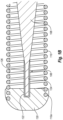
- FIG. 1B a cut-away view of an enlarged portion of the distal end of the guide wire device 100 is illustrated.
- the portion of the guide wire device 100 illustrated in Figure 1B shows the tapered distal section 106, the shapeable distal end section 108, the helical coil section 110, and the atraumatic cap 120.
- the shapeable distal end section 108 includes a distal wire portion 124 composed of a Ni-Ti alloy that extends from the tapered distal section 106.
- the distal wire portion is coated with a layer of solder material 126 (e.g., a gold-tin solder, a gold-indium solder, a gold-germanium solder, a silver-tin solder, a silver-gold-tin solder, or another suitable solder).
- a layer of solder material 126 e.g., a gold-tin solder, a gold-indium solder, a gold-germanium solder, a silver-tin solder, a silver-gold-tin solder, or another suitable solder.
- the helical coil section 110 is attached to the shapeable distal end section 108 by soldering the rounded, atraumatic cap section 120 onto the helical coil section 110 and the shapeable distal end section 108. As illustrated, a portion 110a of the helical coil section 110 is embedded in the atraumatic cap 120, thus attaching the atraumatic cap 120 to the helical coil 120.
- the atraumatic cap 120 forms a soldered joint 122 with the shapeable distal end section 108 by forming a solder bond with the layer of solder material 126 that is in turn bonded to the distal wire portion 124. Because Ni-Ti alloy forms a persistent oxide layer, it can be difficult to solder Ni-Ti. Methods of manufacture will be discussed in detail below.
- the atraumatic cap 120 can readily form a joint 122 with the shapeable distal end section 108.
- the atraumatic cap 120 can be soldered to or formed on the shapeable distal end section 108 without significant loss of the linear pseudoelastic nickel-titanium deformation behavior.
- portions of the guide wire device 100 are coated with a coating 118 of lubricous material such as polytetrafluoroethylene (PTFE) (sold under the trademark Teflon by du Pont, de Nemours & Co.) or other suitable lubricous coatings such as the polysiloxane coatings, polyvinylpyrrolidone (PVP), and the like.
- PTFE polytetrafluoroethylene
- PVP polyvinylpyrrolidone
- the guide wire device 100 that includes a Ni-Ti alloy portion 104 with a shapeable distal end section 108 having linear pseudoelastic characteristics, which facilitates shaping of the distal tip section 108 of the guide wire 100.
- the Ni-Ti alloy portion 104 may also include a superelastic portion proximal to the shapeable distal end section 108 to facilitate the advancing of the guide wire in a body lumen.
- the linear pseudoelastic and superelastic portions exhibit extensive, recoverable strain, which greatly minimizes the risk of damage to arteries during the advancement therein.
- the proximal portion 102 of the guide wire device 100 is typically made from stainless steel.
- Stainless steel is generally significantly stronger, i.e., higher yield strength and ultimate tensile strength, than superelastic or linear pseudo elastic Ni-Ti.
- Suitable high strength materials include 304 or 316L stainless steel, which is a conventional material in guide wire construction.
- Figure 2 contains the elastic component of three idealized stress-strain curves for 316L stainless steel 222, linear pseudoelastic Ni-Ti 218/220, and non-linear pseudoelastic Ni-Ti alloy 200.
- the stress/strain relationship is plotted on x-y axes, with the x axis representing strain and the y axis representing stress.
- curve 200 when stress is applied to a specimen of a Ni-Ti alloy exhibiting non-linear pseudoelastic characteristics at a temperature at or above where the materials is in the austenitic phase, the specimen deforms elastically in region 202 until it reaches a particular stress level where the alloy then undergoes a stress-induced phase transformation from the austenitic phase to the martensitic phase (i.e., the stress-induced martensite phase). As the phase transformation progresses, the alloy undergoes significant increases in strain with little or no corresponding increases in stress. On curve 200, this is represented by the upper, nearly flat stress plateau 204.
- the strain increases while the stress from continued deformation remains essentially constant until the transformation of the austenitic phase to the martensitic phase is complete at approximately region 206. Thereafter, further increase in stress is necessary to cause further deformation to point 208.
- the martensitic metal first yields elastically upon the application of additional stress and then plastically with permanent deformation (not shown).
- the martensitic Ni-Ti alloy elastically recovers and transforms back to the austenitic phase.
- the reduction in stress first causes a decrease in strain along region 210.
- stress reduction reaches the level at which the martensitic phase transforms essentially completely back into the austenitic phase at region 212
- the stress level in the specimen remains essentially constant to continue relieving strain along lower plateau 214 (but less than the constant stress level at which the austenitic crystalline structure transforms to the martensitic crystalline structure until the transformation back to the austenitic phase is complete); i.e., there is significant recovery in strain with only negligible corresponding stress reduction.
- Figure 2 also includes a curve 218/220 representing the idealized behavior of linear pseudoelastic Ni-Ti alloy as utilized in the shapeable distal end section 108 in the present invention.
- the slope of curve 218/220 generally represents the Young's modulus of the linear pseudoelastic Ni-Ti alloy.
- curve 218/220 does not contain any flat plateau stresses found in curve 200. This stands to reason since the Ni-Ti alloy of curve 218-220 remains in the martensitic phase throughout and does not undergo any phase change. To that end, curve 218/220 shows that increasing stress begets a proportional increase in reversible strain, and a release of stress begets a proportional decrease in strain.
- the areas bounded by curves 200 and 218-220 represent the hysteresis in the Ni-Ti alloy.
- Figure 2 also includes curve 220 which is the elastic behavior of a standard 316L stainless steel. Stress is incrementally applied to the steel and, just prior to the metal deforming plastically, decrementally released.
- a method for fabricating a guide wire device includes (1) fabricating an elongate shaft member that includes a proximal end section and a distal end section.
- the distal end section includes a nickel-titanium alloy member that has a first cross-sectional dimension (e.g., a thickness).
- the method further includes (2) dipping at least a portion of the distal end section in a molten solder material to apply (e.g., coat) the molten solder material thereon, (3) cold working at least a portion of the distal end section having the solder material coated thereon, wherein the cold working yields a distal shapeable section having a linear pseudoelastic nickel-titanium microstructure, and (4) soldering the distal shapeable section and a helical coil section disposed about the distal shapeable section to an atraumatic cap without substantial loss of the linear pseudoelasticity of the distal shapeable section.
- fabricating an elongate shaft member that includes a proximal end section and a distal end section may include may include attaching (e.g., by welding) a proximal end section fabricated from a first material such as stainless steel to a distal end section fabricated from a second material such as nickel-titanium alloy.
- the elongate shaft member can be fabricated from a single material such as, but not limited to, a nickel-titanium alloy.
- fabricating an elongate shaft member may further include drawing at least a portion of the elongate shaft member through a drawing die, rolling, calendaring, grinding, or combinations thereof to form or reshape the at least a portion of the elongate shaft member and cleaning the elongate shaft member such as by ultrasonically cleaning.
- Ni-Ti alloys such as those described herein, are very difficult to solder due to the formation of a tenacious, naturally occurring oxide coating which prevents the molten solder from wetting the surface of the alloy. It has been found that by first treating the surface of the Ni-Ti alloy with molten alkali metal hydroxide, e.g., sodium, potassium, lithium or mixtures thereof to form a substantially oxide-free alloy surface and then pretinning (i.e., applying a suitable solder material, such as, a gold-tin solder, a gold-indium solder, a gold-germanium solder, a silver-tin solder, a silver-gold-tin solder, or another suitable solder) without contacting air, that Ni-Ti alloys can be readily soldered in a conventional manner.
- molten alkali metal hydroxide e.g., sodium, potassium, lithium or mixtures thereof
- pretinning i.e., applying a suitable solder material, such as, a
- solder can be applied to at least a portion of the distal end section by dipping the at least the distal end section into a bath, wherein the bath includes an upper layer of a molten metal hydroxide and a lower layer of the molten solder material.
- a layer of solder material can be applied to at least a portion of the distal end section by chemical vapor deposition (CVD), physical vapor deposition (PVD), sputter coating, and the like, and combinations thereof.
- a helical coil section can be assembled around the a distal portion of the elongate shaft member, including the distal shapeable section, and a rounded plug (i.e., an aturaumatic cap section) can be formed at the distal end of the assembly by soldering the distal shapeable section and a helical coil section disposed about the distal shapeable section to the rounded plug without substantial loss of the linear pseudoelasticity of the distal shapeable section.
- the pretinning followed by cold working and forming the atraumatic cap at the distal end of the elongate shaft member yields a user-shapeable distal end section that exhibits linear pseudoelastic deformation behavior without a phase transformation or onset of stress-induced martensite.
- a method for fabricating a guide wire device that has a shapeable distal end section includes (1) providing an elongate shaft member that includes a proximal end section and a distal end section, wherein the distal end section includes a nickel-titanium alloy member, (2) grinding at least a portion of the distal end section to a first cross-sectional dimension, and (3) ultrasonically cleaning at least the distal end section.
- the method further includes (4) dipping at least a portion of the distal end section into a bath of a molten solder material, wherein the bath of molten solder material includes an upper layer of a molten metal hydroxide and a lower layer of the molten solder material, and (5) cold working at least a portion of the distal end section, wherein the cold working yields a distal shapeable section having a linear pseudoelastic nickel-titanium microstructure.
- the method continues with (6) ultrasonically cleaning at least the distal end section, (7) disposing a helical coil section about the distal shapeable section, and (8) forming an atraumatic cap section coupling the helical coil section and the distal shapeable section via a soldered joint, wherein the soldered joint is formed without loss of the linear elastic nickel-titanium microstructure.
- Ni-Ti alloys such as those described herein, are very difficult to solder due to the formation of a tenacious, naturally occurring oxide coating which prevents the molten solder from wetting the surface of the alloy in a manner necessary to develop a sound, essentially oxide free, soldered joint. It has been found that by first treating the surface of the Ni-Ti alloy with molten alkali metal hydroxide, e.g., a hydroxide of sodium, potassium, lithium, or mixtures thereof to form a sufficiently oxide free alloy surface and then pretinning with a suitable solder such as a gold-tin solder or the like without contacting air, that the Ni-Ti piece can be readily soldered in a conventional manner.
- molten alkali metal hydroxide e.g., a hydroxide of sodium, potassium, lithium, or mixtures thereof
- a presently preferred alkali metal hydroxide is a mixture of about 59% KOH and about 41% NaOH.
- the solder may have a melting point temperature in a range of about 150 °C to about 350 °C or about 280 °C to about 300 °C.
- the solder may contain from about 60 to about 85% gold and the balance tin, with the presently preferred solder containing about 80% gold and about 20% tin.
- Other suitable solders may include gold-indium, gold-germanium, silver-tin, and silver-gold-tin.
- a multilayered bath is provided with an upper layer of molten alkali metal hydroxide and a lower layer of molten gold-tin solder.
- the part of the superelastic distal portion, which is to be soldered, is thrust into the multilayered bath through the upper surface of the molten alkali metal hydroxide which removes the oxide coating, leaving a sufficiently oxide free alloy surface, and then into the molten solder which wets the cleaned surface.
- the solder solidifies upon removal from the molten solder into a thin coating on the metal alloy surface, the underlying alloy surface is protected from the oxygen-containing atmosphere.
- any of the alkali metal hydroxide on the surface of the solder can be easily removed with water without detrimentally affecting either the pretinned layer or the underlying alloy surface.
- the pretinned Ni-Ti member is then ready for further processing and/or soldering.
- the pretinning procedure may be employed for soldering other metal alloys having significant titanium levels.
- the distal end section may be drawn and ground to a first dimension (e.g., about 0.08 mm), ultrasonically cleaned, and pretinned according to the method described above.
- the distal end section can be dipped in the molten solder material at least a second time if a thicker coating of solder is desired or if the distal end section was not completely coated in the first dip. After pretinning, the distal end section is cold-worked, ultrasonically cleaned, and soldered using conventional soldering procedures.
- Suitable examples of cold working procedures that can be used to cold work the distal end section include, but are not limited to, high force flattening, stamping, rolling, calendaring, and combinations thereof. High force flattening is the currently preferred cold-working procedure.
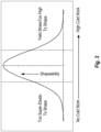
- Figure 3 is a diagram schematically illustrating the relationship between degree of cold work and shapeability of a Ni-Ti alloy. As can be seen in Figure 3 , when superelastic Ni-Ti has little or no cold work, the material has too much superelastic character to be shaped. At the other end of the spectrum, Ni-Ti alloy material that has too much cold work becomes essentially unshapeable by manual means because its yield stress is too high.
- Ni-Ti alloy may be shapeable, but the stress that must be exceeded to exceed the elastic limit of the material (i.e., the yield stress) is too high to be conveniently shaped by hand.
- the degree of cold work is such that the Ni-Ti material is highly shapeable.
- Figure 4 illustrates the yield stress of samples of Ni-Ti alloy having various degrees of cold work.
- the as-ground (0.08 mm) sample is illustrated at curve 402.
- the superelastic, as-ground material cannot be permanently deformed with any degree of reliability.
- Curves 404-410 illustrate the effect associated with increasing amounts of cold work.
- the sample illustrated in curve 404 was flattened from the as-ground diameter of about 0.08 mm to about 0.045 mm, which corresponds to about 45 % cold work.
- the sample illustrated in curve 404 has a yield stress of about 1200 MPa (-175 ksi).
- the samples illustrated in curves 406 and 408 were flattened from the as-ground diameter of about 0.08 mm to about 0.041 mm and 0.036 mm (respectively), which corresponds to about 49-55 % cold work.
- the samples illustrated in curves 406 and 408 have yield stresses of about 1900 MPa (-275 ksi).
- the sample illustrated in curve 410 was flattened from the as-ground diameter of about 0.08 mm to about 0.028 mm, which corresponds to about 65 % cold work.
- the sample illustrated in curve 410 has a yield stress of about 2070 MPa (-300 ksi).
- the distal shapeable section can be cold-worked to have a yield stress in a range of about 690 MPa (-100 ksi) to about 2070 MPa (-300 ksi) or about 1034 MPa (-150 ksi) to about 1380 MPa (-200 ksi). Yield stresses in these ranges are obtained when the distal shapeable section that has a cold-worked microstructure that includes about 25 % to about 65 % cold work, about 40 % to about 50 % cold work, or about 45 % cold work.
- the linear pseudoelastic microstructure can be lost if the Ni-Ti material is heated after cold working.
- Figure 5 shows the progressive loss of linear pseudoelastic character of Ni-Ti alloy as a result of moderate heat exposure for varying amounts of time.
- Figure 5 illustrates the loss of cold work in three samples of cold-worked Ni-Ti alloy having been exposed to 300 °C heat treatment for 2 minutes, 20 minutes, and 180 minutes. Curves in region 500 show more linear pseudoelastic behavior, while curves in region 510 show more superelastic behavior. All curves show potentially significant loss of cold work induced linear pseudoelastic behavior.
- soldering leads to significant loss of cold work in the distal shapeable section. This is believed to be due to the fact that soldering involves only localized application heat as opposed to solder dipping, which involves general application of heat that could lead to potentially significant loss of cold work induced linear pseudoelastic behavior.
Landscapes
- Engineering & Computer Science (AREA)
- Chemical & Material Sciences (AREA)
- Mechanical Engineering (AREA)
- Physics & Mathematics (AREA)
- Health & Medical Sciences (AREA)
- Organic Chemistry (AREA)
- Metallurgy (AREA)
- Materials Engineering (AREA)
- Crystallography & Structural Chemistry (AREA)
- Thermal Sciences (AREA)
- Life Sciences & Earth Sciences (AREA)
- Pulmonology (AREA)
- Public Health (AREA)
- Veterinary Medicine (AREA)
- General Health & Medical Sciences (AREA)
- Animal Behavior & Ethology (AREA)
- Hematology (AREA)
- Heart & Thoracic Surgery (AREA)
- Biomedical Technology (AREA)
- Anesthesiology (AREA)
- Biophysics (AREA)
- Media Introduction/Drainage Providing Device (AREA)
- Materials For Medical Uses (AREA)
Applications Claiming Priority (3)
| Application Number | Priority Date | Filing Date | Title |
|---|---|---|---|
| US13/172,278 US9724494B2 (en) | 2011-06-29 | 2011-06-29 | Guide wire device including a solderable linear elastic nickel-titanium distal end section and methods of preparation therefor |
| EP12733280.7A EP2726138B1 (de) | 2011-06-29 | 2012-06-18 | Führungsdrahtvorrichtung mit einer lötfähigen linearelastischen nickel-titan-distalspitze und verfahren zu ihrer herstellung |
| PCT/US2012/042991 WO2013003098A1 (en) | 2011-06-29 | 2012-06-18 | A guide wire device including a solderable linear elastic nickel-titanium distal end section and methods of preparation therefor |
Related Parent Applications (1)
| Application Number | Title | Priority Date | Filing Date |
|---|---|---|---|
| EP12733280.7A Division EP2726138B1 (de) | 2011-06-29 | 2012-06-18 | Führungsdrahtvorrichtung mit einer lötfähigen linearelastischen nickel-titan-distalspitze und verfahren zu ihrer herstellung |
Publications (1)
| Publication Number | Publication Date |
|---|---|
| EP4159264A1 true EP4159264A1 (de) | 2023-04-05 |
Family
ID=46466855
Family Applications (2)
| Application Number | Title | Priority Date | Filing Date |
|---|---|---|---|
| EP22208791.8A Pending EP4159264A1 (de) | 2011-06-29 | 2012-06-18 | Führungsdrahtvorrichtung mit lötbarem linearem elastischem nickel-titan-distalendteil und herstellungsverfahren dafür |
| EP12733280.7A Active EP2726138B1 (de) | 2011-06-29 | 2012-06-18 | Führungsdrahtvorrichtung mit einer lötfähigen linearelastischen nickel-titan-distalspitze und verfahren zu ihrer herstellung |
Family Applications After (1)
| Application Number | Title | Priority Date | Filing Date |
|---|---|---|---|
| EP12733280.7A Active EP2726138B1 (de) | 2011-06-29 | 2012-06-18 | Führungsdrahtvorrichtung mit einer lötfähigen linearelastischen nickel-titan-distalspitze und verfahren zu ihrer herstellung |
Country Status (4)
| Country | Link |
|---|---|
| US (3) | US9724494B2 (de) |
| EP (2) | EP4159264A1 (de) |
| JP (2) | JP6223969B2 (de) |
| WO (1) | WO2013003098A1 (de) |
Families Citing this family (12)
| Publication number | Priority date | Publication date | Assignee | Title |
|---|---|---|---|---|
| US11298251B2 (en) | 2010-11-17 | 2022-04-12 | Abbott Cardiovascular Systems, Inc. | Radiopaque intraluminal stents comprising cobalt-based alloys with primarily single-phase supersaturated tungsten content |
| JP5382953B2 (ja) * | 2011-01-28 | 2014-01-08 | 朝日インテック株式会社 | ガイドワイヤ |
| US9724494B2 (en) | 2011-06-29 | 2017-08-08 | Abbott Cardiovascular Systems, Inc. | Guide wire device including a solderable linear elastic nickel-titanium distal end section and methods of preparation therefor |
| US20130046286A1 (en) * | 2011-08-17 | 2013-02-21 | Abbott Cardiovascular Systems | Narrow hysteresis ni-ti core wire for enhanced guide wire steering response |
| US9078740B2 (en) | 2013-01-21 | 2015-07-14 | Howmedica Osteonics Corp. | Instrumentation and method for positioning and securing a graft |
| WO2017184778A1 (en) | 2016-04-20 | 2017-10-26 | Arconic Inc. | Fcc materials of aluminum, cobalt and nickel, and products made therefrom |
| CA3016761A1 (en) | 2016-04-20 | 2017-10-26 | Arconic Inc. | Fcc materials of aluminum, cobalt, iron and nickel, and products made therefrom |
| EP4023279A4 (de) * | 2019-08-30 | 2023-06-07 | Asahi Intecc Co., Ltd. | Führungsdraht und verfahren zur herstellung eines führungsdrahtes |
| US12151049B2 (en) | 2019-10-14 | 2024-11-26 | Abbott Cardiovascular Systems, Inc. | Methods for manufacturing radiopaque intraluminal stents comprising cobalt-based alloys with supersaturated tungsten content |
| US11285299B2 (en) | 2019-10-31 | 2022-03-29 | Abbott Cardiovascular Systems Inc. | Mold for forming solder distal tip for guidewire |
| JP7689981B2 (ja) * | 2020-10-30 | 2025-06-09 | テルモ株式会社 | ガイドワイヤおよびガイドワイヤの製造方法 |
| JP7759336B2 (ja) * | 2020-10-30 | 2025-10-23 | テルモ株式会社 | ガイドワイヤおよびガイドワイヤの製造方法 |
Citations (6)
| Publication number | Priority date | Publication date | Assignee | Title |
|---|---|---|---|---|
| US20040167442A1 (en) * | 2003-02-26 | 2004-08-26 | Shireman Brice L. | Elongated intracorporal medical device |
| US20050124917A1 (en) * | 2003-12-05 | 2005-06-09 | Scimed Life Systems, Inc. | Elongated medical device for intracorporal use |
| EP1731241A1 (de) * | 2005-06-06 | 2006-12-13 | Asahi Intecc Co., Ltd. | Formwerkzeug zum Erwarmen sowie Verfahren zur Herstellung eines Führungsdrahtes unter Verwendung dieses Formwerkzeugs |
| WO2008022126A1 (en) * | 2006-08-16 | 2008-02-21 | Boston Scientific Limited | Mechanical honing of metallic tubing for soldering in a medical device construction |
| WO2010107798A1 (en) * | 2009-03-17 | 2010-09-23 | Abbott Cardiovascular Systems Inc. | Guide wire with core having welded wire segments |
| US20120041342A1 (en) * | 2010-08-16 | 2012-02-16 | Abbott Cardiovascular Systems Inc. | High durability coronary guide wire |
Family Cites Families (253)
| Publication number | Priority date | Publication date | Assignee | Title |
|---|---|---|---|---|
| US2938850A (en) | 1957-06-10 | 1960-05-31 | William E Collins | Work holder for electroplating |
| DE1107043B (de) | 1959-11-20 | 1961-05-18 | Siemens Ag | Bad und Verfahren zum anodischen Glaenzen von Metallen und Metallegierungen |
| US3612058A (en) | 1968-04-17 | 1971-10-12 | Electro Catheter Corp | Catheter stylets |
| US3635703A (en) | 1969-03-14 | 1972-01-18 | Gregory J Pissarevsky | Ornamental watch case |
| DE2243374C3 (de) * | 1972-09-02 | 1975-11-13 | Stannol-Loetmittelfabrik Wilhelm Paff, 5600 Wuppertal | Flußmittel für Weichlote |
| JPS5018315A (de) | 1973-05-30 | 1975-02-26 | ||
| US4127459A (en) | 1977-09-01 | 1978-11-28 | Jumer John F | Method and apparatus for incremental electro-polishing |
| US4330381A (en) | 1978-09-18 | 1982-05-18 | Jumer John F | Method for containerless portable electro-polishing |
| US4654092A (en) * | 1983-11-15 | 1987-03-31 | Raychem Corporation | Nickel-titanium-base shape-memory alloy composite structure |
| US4685977A (en) | 1984-12-03 | 1987-08-11 | General Electric Company | Fatigue-resistant nickel-base superalloys and method |
| SE453258B (sv) | 1986-04-21 | 1988-01-25 | Medinvent Sa | Elastisk, sjelvexpanderande protes samt forfarande for dess framstellning |
| US4854330A (en) * | 1986-07-10 | 1989-08-08 | Medrad, Inc. | Formed core catheter guide wire assembly |
| US5171383A (en) * | 1987-01-07 | 1992-12-15 | Terumo Kabushiki Kaisha | Method of manufacturing a differentially heat treated catheter guide wire |
| US5174295A (en) * | 1987-04-10 | 1992-12-29 | Cardiometrics, Inc. | Apparatus, system and method for measuring spatial average velocity and/or volumetric flow of blood in a vessel and screw joint for use therewith |
| US4967753A (en) * | 1987-04-10 | 1990-11-06 | Cardiometrics, Inc. | Apparatus, system and method for measuring spatial average velocity and/or volumetric flow of blood in a vessel |
| US4846186A (en) * | 1988-01-12 | 1989-07-11 | Cordis Corporation | Flexible guidewire |
| US5067489A (en) * | 1988-08-16 | 1991-11-26 | Flexmedics Corporation | Flexible guide with safety tip |
| US5480382A (en) * | 1989-01-09 | 1996-01-02 | Pilot Cardiovascular Systems, Inc. | Steerable medical device |
| EP0395098B1 (de) * | 1989-04-28 | 1994-04-06 | Tokin Corporation | Schnell betriebsbereiter Führungsdraht für Katheter unter Anwendung einer Memory-Legierung mit Pseudoelastizität |
| US5477864A (en) | 1989-12-21 | 1995-12-26 | Smith & Nephew Richards, Inc. | Cardiovascular guidewire of enhanced biocompatibility |
| US5238004A (en) * | 1990-04-10 | 1993-08-24 | Boston Scientific Corporation | High elongation linear elastic guidewire |
| JP3297434B2 (ja) * | 1990-04-10 | 2002-07-02 | ボストン サイエンティフィック コーポレーション | 高伸長型線形弾性ガイドワイヤ |
| US5147317A (en) * | 1990-06-04 | 1992-09-15 | C.R. Bard, Inc. | Low friction varied radiopacity guidewire |
| US5433200A (en) * | 1990-07-09 | 1995-07-18 | Lake Region Manufacturing, Inc. | Low profile, coated, steerable guide wire |
| US5330826A (en) | 1990-08-13 | 1994-07-19 | Mcdonnell Douglas Corporation | Preparation of ceramic-metal coatings |
| US5174302A (en) * | 1990-12-04 | 1992-12-29 | Cordis Corporation | Variable radiopacity guidewire with spaced highly radiopaque regions |
| US5341818A (en) * | 1992-12-22 | 1994-08-30 | Advanced Cardiovascular Systems, Inc. | Guidewire with superelastic distal portion |
| US6682608B2 (en) * | 1990-12-18 | 2004-01-27 | Advanced Cardiovascular Systems, Inc. | Superelastic guiding member |
| US6165292A (en) * | 1990-12-18 | 2000-12-26 | Advanced Cardiovascular Systems, Inc. | Superelastic guiding member |
| US5353798A (en) * | 1991-03-13 | 1994-10-11 | Scimed Life Systems, Incorporated | Intravascular imaging apparatus and methods for use and manufacture |
| US5354623A (en) * | 1991-05-21 | 1994-10-11 | Cook Incorporated | Joint, a laminate, and a method of preparing a nickel-titanium alloy member surface for bonding to another layer of metal |
| US5184621A (en) * | 1991-05-29 | 1993-02-09 | C. R. Bard, Inc. | Steerable guidewire having electrodes for measuring vessel cross-section and blood flow |
| CA2380683C (en) | 1991-10-28 | 2006-08-08 | Advanced Cardiovascular Systems, Inc. | Expandable stents and method for making same |
| US5353808A (en) * | 1992-03-04 | 1994-10-11 | Cordis Corporation | Guidewire having distally located marker segment |
| JPH07505316A (ja) | 1992-03-31 | 1995-06-15 | ボストン サイエンティフィック コーポレーション | 医療用ワイヤ |
| US5776080A (en) * | 1992-08-12 | 1998-07-07 | Scimed Life Systems, Inc. | Shaft movement control apparatus |
| US5287858A (en) * | 1992-09-23 | 1994-02-22 | Pilot Cardiovascular Systems, Inc. | Rotational atherectomy guidewire |
| WO1994012234A1 (en) * | 1992-12-01 | 1994-06-09 | Intelliwire, Inc. | Vibratory element for crossing stenoses |
| US20050059889A1 (en) | 1996-10-16 | 2005-03-17 | Schneider (Usa) Inc., A Minnesota Corporation | Clad composite stent |
| US5630840A (en) | 1993-01-19 | 1997-05-20 | Schneider (Usa) Inc | Clad composite stent |
| CA2152594C (en) | 1993-01-19 | 1998-12-01 | David W. Mayer | Clad composite stent |
| US5441515A (en) | 1993-04-23 | 1995-08-15 | Advanced Cardiovascular Systems, Inc. | Ratcheting stent |
| US7883474B1 (en) * | 1993-05-11 | 2011-02-08 | Target Therapeutics, Inc. | Composite braided guidewire |
| DK0625358T3 (da) * | 1993-05-19 | 1996-08-05 | Schneider Europ Ag | Styretråd |
| JP3176193B2 (ja) | 1993-09-22 | 2001-06-11 | アイシン精機株式会社 | 表面処理用回転治具 |
| US5404887A (en) * | 1993-11-04 | 1995-04-11 | Scimed Life Systems, Inc. | Guide wire having an unsmooth exterior surface |
| JPH0737199U (ja) * | 1993-12-24 | 1995-07-11 | テルモ株式会社 | ガイドワイヤー |
| JP2703510B2 (ja) | 1993-12-28 | 1998-01-26 | アドヴァンスド カーディオヴァスキュラー システムズ インコーポレーテッド | 拡大可能なステント及びその製造方法 |
| JP3725900B2 (ja) | 1994-01-14 | 2005-12-14 | アドヴァンスト・カーディオヴァスキュラー・システムズ・インコーポレイテッド | 超弾性遠位部分を有するガイドワイヤ |
| US6165210A (en) | 1994-04-01 | 2000-12-26 | Gore Enterprise Holdings, Inc. | Self-expandable helical intravascular stent and stent-graft |
| CA2147709C (en) | 1994-04-25 | 1999-08-24 | Sharon S. Lam | Radiopaque stent markers |
| US5666969A (en) * | 1994-05-18 | 1997-09-16 | Scimed Life Systems, Inc. | Guidewire having multiple radioscopic coils |
| US5636641A (en) | 1994-07-25 | 1997-06-10 | Advanced Cardiovascular Systems, Inc. | High strength member for intracorporeal use |
| US5673707A (en) * | 1994-09-23 | 1997-10-07 | Boston Scientific Corporation | Enhanced performance guidewire |
| DE69415531T2 (de) | 1994-10-24 | 1999-07-01 | Ivoclar Ag, Schaan | Verfahren zur Herstellung von Metallgussteilen |
| CA2163824C (en) | 1994-11-28 | 2000-06-20 | Richard J. Saunders | Method and apparatus for direct laser cutting of metal stents |
| US5916178A (en) * | 1995-03-30 | 1999-06-29 | Medtronic, Inc. | Steerable high support guidewire with thin wall nitinol tube |
| BE1009277A3 (fr) | 1995-04-12 | 1997-01-07 | Corvita Europ | Tuteur auto-expansible pour dispositif medical a introduire dans une cavite d'un corps, et son procede de preparation. |
| CA2216943C (en) | 1995-04-19 | 2003-06-17 | Boston Scientific Limited | Drug release coated stent |
| JP3506532B2 (ja) | 1995-05-02 | 2004-03-15 | 日本エレクトロプレイテイング・エンジニヤース株式会社 | 白金及び白金合金の電解研磨液 |
| JPH11504829A (ja) * | 1995-05-05 | 1999-05-11 | アドバンスト・カーディオバスキュラー・システムズ・インコーポレイテッド | 減摩面を有する管内装置 |
| US5716417A (en) | 1995-06-07 | 1998-02-10 | St. Jude Medical, Inc. | Integral supporting structure for bioprosthetic heart valve |
| EP0755693A1 (de) * | 1995-07-18 | 1997-01-29 | Schneider (Europe) Ag | Katheter-Führungsdraht |
| US5746701A (en) * | 1995-09-14 | 1998-05-05 | Medtronic, Inc. | Guidewire with non-tapered tip |
| US6004279A (en) * | 1996-01-16 | 1999-12-21 | Boston Scientific Corporation | Medical guidewire |
| US6334871B1 (en) | 1996-03-13 | 2002-01-01 | Medtronic, Inc. | Radiopaque stent markers |
| US5891191A (en) | 1996-04-30 | 1999-04-06 | Schneider (Usa) Inc | Cobalt-chromium-molybdenum alloy stent and stent-graft |
| US6027528A (en) | 1996-05-28 | 2000-02-22 | Cordis Corporation | Composite material endoprosthesis |
| US5865767A (en) * | 1996-07-10 | 1999-02-02 | Cordis Corporation | Guidewire having compound taper |
| US5980706A (en) | 1996-07-15 | 1999-11-09 | Semitool, Inc. | Electrode semiconductor workpiece holder |
| US5803344A (en) * | 1996-09-09 | 1998-09-08 | Delco Electronics Corp. | Dual-solder process for enhancing reliability of thick-film hybrid circuits |
| US5858556A (en) | 1997-01-21 | 1999-01-12 | Uti Corporation | Multilayer composite tubular structure and method of making |
| US6190332B1 (en) * | 1998-02-19 | 2001-02-20 | Percusurge, Inc. | Core wire with shapeable tip |
| US7455646B2 (en) * | 1997-06-04 | 2008-11-25 | Advanced Cardiovascular Systems, Inc. | Polymer coated guide wire |
| US7494474B2 (en) * | 1997-06-04 | 2009-02-24 | Advanced Cardiovascular Systems, Inc. | Polymer coated guidewire |
| US5746691A (en) | 1997-06-06 | 1998-05-05 | Global Therapeutics, Inc. | Method for polishing surgical stents |
| JP3645399B2 (ja) | 1997-06-09 | 2005-05-11 | 住友金属工業株式会社 | 血管内ステント |
| DE69838256T2 (de) | 1997-09-24 | 2008-05-15 | Med Institute, Inc., West Lafayette | Radial aufweitbarer stent |
| US6159165A (en) * | 1997-12-05 | 2000-12-12 | Micrus Corporation | Three dimensional spherical micro-coils manufactured from radiopaque nickel-titanium microstrand |
| US6245030B1 (en) * | 1998-03-04 | 2001-06-12 | C. R. Bard, Inc. | Flexible kink resistant, low friction guidewire with formable tip, and method for making same |
| EA001993B1 (ru) | 1998-04-06 | 2001-10-22 | Конинклейке Филипс Электроникс Н.В. | Способ электрохимической обработки заготовки и устройство для его осуществления |
| US6139511A (en) * | 1998-06-29 | 2000-10-31 | Advanced Cardiovascular Systems, Inc. | Guidewire with variable coil configuration |
| US7887578B2 (en) | 1998-09-05 | 2011-02-15 | Abbott Laboratories Vascular Enterprises Limited | Stent having an expandable web structure |
| US6508803B1 (en) * | 1998-11-06 | 2003-01-21 | Furukawa Techno Material Co., Ltd. | Niti-type medical guide wire and method of producing the same |
| US6234981B1 (en) * | 1998-12-30 | 2001-05-22 | Advanced Cardiovascular Systems, Inc. | Vapor deposition coated intracorporeal device |
| US7645242B1 (en) * | 1998-12-31 | 2010-01-12 | Advanced Cardiovascular Systems, Inc. | Composite guidewire with drawn and filled tube construction |
| US6620192B1 (en) | 1999-03-16 | 2003-09-16 | Advanced Cardiovascular Systems, Inc. | Multilayer stent |
| CA2336416A1 (en) * | 1999-04-30 | 2000-11-09 | Gono Usami | Catheter and guide wire |
| WO2000065987A1 (en) * | 1999-04-30 | 2000-11-09 | Applied Medical Resources Corporation | Guidewire |
| US6375676B1 (en) | 1999-05-17 | 2002-04-23 | Advanced Cardiovascular Systems, Inc. | Self-expanding stent with enhanced delivery precision and stent delivery system |
| US6540774B1 (en) | 1999-08-31 | 2003-04-01 | Advanced Cardiovascular Systems, Inc. | Stent design with end rings having enhanced strength and radiopacity |
| AU6941800A (en) | 1999-09-03 | 2001-04-10 | Advanced Cardiovascular Systems Inc. | A porous prosthesis and a method of depositing substances into the pores |
| US6355058B1 (en) | 1999-12-30 | 2002-03-12 | Advanced Cardiovascular Systems, Inc. | Stent with radiopaque coating consisting of particles in a binder |
| US6375826B1 (en) | 2000-02-14 | 2002-04-23 | Advanced Cardiovascular Systems, Inc. | Electro-polishing fixture and electrolyte solution for polishing stents and method |
| US7250058B1 (en) | 2000-03-24 | 2007-07-31 | Abbott Cardiovascular Systems Inc. | Radiopaque intraluminal stent |
| US7632303B1 (en) * | 2000-06-07 | 2009-12-15 | Advanced Cardiovascular Systems, Inc. | Variable stiffness medical devices |
| US20030077200A1 (en) | 2000-07-07 | 2003-04-24 | Craig Charles H. | Enhanced radiopaque alloy stent |
| JP3560907B2 (ja) * | 2000-09-05 | 2004-09-02 | 株式会社古河テクノマテリアル | NiTi系合金ワイヤ、その製造方法および前記NiTi系合金ワイヤを用いたカテーテル用ガイドワイヤ |
| US6602272B2 (en) | 2000-11-02 | 2003-08-05 | Advanced Cardiovascular Systems, Inc. | Devices configured from heat shaped, strain hardened nickel-titanium |
| US6500130B2 (en) * | 2000-12-21 | 2002-12-31 | Scimed Life Systems, Inc. | Steerable guidewire |
| US8100837B1 (en) * | 2000-12-21 | 2012-01-24 | Abbott Cardiovascular Systems, Inc. | Superelastic guidewire with locally altered properties |
| US6669652B2 (en) * | 2000-12-21 | 2003-12-30 | Advanced Cardiovascular Systems, Inc. | Guidewire with tapered distal coil |
| US6599415B1 (en) | 2001-04-30 | 2003-07-29 | Advanced Cardiovascular Systems, Inc. | Apparatus and method for electropolishing surfaces |
| US6679980B1 (en) | 2001-06-13 | 2004-01-20 | Advanced Cardiovascular Systems, Inc. | Apparatus for electropolishing a stent |
| EP1432467B1 (de) * | 2001-10-05 | 2005-12-14 | Boston Scientific Limited | Kompositführungsdraht |
| AU2002354033A1 (en) * | 2001-11-05 | 2003-05-19 | Memry Corporation | Work-hardened pseudoelastic guide wires |
| US6832715B2 (en) * | 2001-12-03 | 2004-12-21 | Scimed Life Systems, Inc. | Guidewire distal tip soldering method |
| JP3762290B2 (ja) * | 2001-12-03 | 2006-04-05 | 朝日インテック株式会社 | 医療用ガイドワイヤ |
| CA2365749A1 (en) | 2001-12-20 | 2003-06-20 | The Governors Of The University Of Alberta | An electrodeposition process and a layered composite material produced thereby |
| US6503290B1 (en) | 2002-03-01 | 2003-01-07 | Praxair S.T. Technology, Inc. | Corrosion resistant powder and coating |
| JP3891274B2 (ja) | 2002-03-14 | 2007-03-14 | セイコーエプソン株式会社 | 記録装置 |
| US20070219464A1 (en) * | 2002-03-22 | 2007-09-20 | Stephen Davis | Guidewire with deflectable re-entry tip |
| US7128718B2 (en) * | 2002-03-22 | 2006-10-31 | Cordis Corporation | Guidewire with deflectable tip |
| US7351214B2 (en) * | 2002-03-22 | 2008-04-01 | Cordis Corporation | Steerable balloon catheter |
| US7481778B2 (en) * | 2002-03-22 | 2009-01-27 | Cordis Corporation | Guidewire with deflectable tip having improved flexibility |
| US7022086B2 (en) * | 2002-05-21 | 2006-04-04 | Scimed Life Systems, Inc. | Guidewire with encapsulated marker |
| GB2389370B (en) | 2002-06-06 | 2006-07-12 | Anopol Ltd | Improvements in stent manufacture |
| WO2004011076A2 (en) * | 2002-07-25 | 2004-02-05 | Boston Scientific Limited | Medical device for navigation through anatomy and method of making same |
| US7357854B1 (en) | 2002-08-19 | 2008-04-15 | Advanced Cardiovascular Systems, Inc. | Process for electropolishing a device made from cobalt-chromium |
| JP4138582B2 (ja) * | 2002-08-23 | 2008-08-27 | テルモ株式会社 | ガイドワイヤ |
| WO2004028340A2 (en) | 2002-09-26 | 2004-04-08 | Advanced Bio Prosthetic Surfaces, Ltd. | High strength vacuum deposited nitionol alloy films, medical thin film graft materials and method of making same |
| US7331986B2 (en) | 2002-10-09 | 2008-02-19 | Boston Scientific Scimed, Inc. | Intraluminal medical device having improved visibility |
| US7144422B1 (en) | 2002-11-13 | 2006-12-05 | Advanced Cardiovascular Systems, Inc. | Drug-eluting stent and methods of making the same |
| JP2006514848A (ja) | 2002-11-13 | 2006-05-18 | セタゴン インコーポレーティッド | 多孔質層を有する医療装置およびその作製方法 |
| US7105018B1 (en) | 2002-12-30 | 2006-09-12 | Advanced Cardiovascular Systems, Inc. | Drug-eluting stent cover and method of use |
| US6916409B1 (en) | 2002-12-31 | 2005-07-12 | Advanced Cardiovascular Systems, Inc. | Apparatus and process for electrolytic removal of material from a medical device |
| US7294214B2 (en) | 2003-01-08 | 2007-11-13 | Scimed Life Systems, Inc. | Medical devices |
| US7156869B1 (en) | 2003-01-27 | 2007-01-02 | Advanced Cardiovascular Systems, Inc. | Drug-eluting stent and delivery system with tapered stent in shoulder region |
| ATE343403T1 (de) | 2003-02-10 | 2006-11-15 | Heraeus Gmbh W C | Verbesserte metalllegierung für medizinische geräte und implantate |
| US7169118B2 (en) * | 2003-02-26 | 2007-01-30 | Scimed Life Systems, Inc. | Elongate medical device with distal cap |
| US7625401B2 (en) | 2003-05-06 | 2009-12-01 | Abbott Laboratories | Endoprosthesis having foot extensions |
| US7520947B2 (en) | 2003-05-23 | 2009-04-21 | Ati Properties, Inc. | Cobalt alloys, methods of making cobalt alloys, and implants and articles of manufacture made therefrom |
| WO2005014095A1 (en) * | 2003-08-07 | 2005-02-17 | Brivant Research & Development Limited | A guide wire for use with a catheter |
| JP3797990B2 (ja) * | 2003-08-08 | 2006-07-19 | 株式会社東芝 | 熱硬化性フラックス及びはんだペースト |
| US20050054952A1 (en) * | 2003-09-05 | 2005-03-10 | Scimed Life Systems, Inc. | Elongated medical device for intracorporal use |
| US20050060025A1 (en) | 2003-09-12 | 2005-03-17 | Mackiewicz David A. | Radiopaque markers for medical devices |
| US7488343B2 (en) | 2003-09-16 | 2009-02-10 | Boston Scientific Scimed, Inc. | Medical devices |
| US7744645B2 (en) * | 2003-09-29 | 2010-06-29 | Medtronic Vascular, Inc. | Laminated drug-polymer coated stent with dipped and cured layers |
| JP3726266B2 (ja) * | 2003-10-02 | 2005-12-14 | 朝日インテック株式会社 | 医療用ガイドワイヤの先端部構造 |
| US7329383B2 (en) | 2003-10-22 | 2008-02-12 | Boston Scientific Scimed, Inc. | Alloy compositions and devices including the compositions |
| US7252746B2 (en) | 2003-11-12 | 2007-08-07 | Cook Incorporated | Electropolishing apparatus and method for medical implants |
| CN100558423C (zh) * | 2003-12-18 | 2009-11-11 | 泰尔茂株式会社 | 导向线 |
| US7824345B2 (en) * | 2003-12-22 | 2010-11-02 | Boston Scientific Scimed, Inc. | Medical device with push force limiter |
| US7153411B2 (en) | 2003-12-30 | 2006-12-26 | Boston Scientific Scimed, Inc. | Method for cleaning and polishing metallic alloys and articles cleaned or polished thereby |
| US20050288773A1 (en) | 2004-01-22 | 2005-12-29 | Glocker David A | Radiopaque coating for biomedical devices |
| NL1025446C2 (nl) | 2004-02-09 | 2005-08-10 | Besi Plating B V | Werkwijze en inrichting voor het elektrolytisch doen toenemen van de dikte van een elektrisch geleidend patroon op een dielektrische drager alsmede dielektrische drager. |
| GB2410901B (en) * | 2004-02-11 | 2008-09-24 | Mediplus Ltd | Catheter guide wire |
| JP2007528301A (ja) | 2004-03-11 | 2007-10-11 | メムリー コーポレーション | 金属部品の疲労寿命を改善する仕上処理 |
| EP1727584B1 (de) * | 2004-03-26 | 2011-01-19 | Lake Region Medical R&D Limited | Medizinischer Führungsdraht mit distalen Kante |
| DE102004023642A1 (de) * | 2004-05-10 | 2005-12-08 | Restate Patent Ag | Katheter-Führungsdraht insbesondere für die perkutane transluminale Coronar-Angioplastik |
| US7498062B2 (en) | 2004-05-26 | 2009-03-03 | Wd Media, Inc. | Method and apparatus for applying a voltage to a substrate during plating |
| ITRM20040271A1 (it) | 2004-05-31 | 2004-08-31 | Cnr Consiglio Naz Delle Ricer | Dispositivo scintigrafico con risoluzione variabile. |
| US20050273156A1 (en) | 2004-06-07 | 2005-12-08 | Rober Burgermeister | Biocompatible alloy for implantable medical devices |
| EP1604697A1 (de) | 2004-06-09 | 2005-12-14 | J.A.C.C. GmbH | Implantierbare Vorrichtung |
| EP1632584A1 (de) | 2004-09-06 | 2006-03-08 | Eidgenössische Technische Hochschule Zürich | Amorphe Legierungen auf der Basis von Zr und deren Anwendung |
| US20060079954A1 (en) | 2004-10-08 | 2006-04-13 | Robert Burgermeister | Geometry and material for high strength, high flexibility, controlled recoil stent |
| WO2006054358A1 (ja) | 2004-11-19 | 2006-05-26 | Iwate University | 生体用合金のNi微量不純物によるアレルギー毒性を無害化する方法 |
| US20060129226A1 (en) | 2004-12-10 | 2006-06-15 | Robert Burgermeister | Material for flexible connectors in high strength, high flexibility, controlled recoil stent |
| FR2883576B1 (fr) | 2005-02-09 | 2009-05-29 | Frederic Vacheron | Procede de traitement de surface de pieces creuses, cuve de mise en oeuvre d'un tel procede, procede et installation de traitement de surface en continu utilisant une telle cuve |
| US20060190070A1 (en) | 2005-02-23 | 2006-08-24 | Dieck Martin S | Rail stent and methods of use |
| US7540995B2 (en) | 2005-03-03 | 2009-06-02 | Icon Medical Corp. | Process for forming an improved metal alloy stent |
| US20060259126A1 (en) | 2005-05-05 | 2006-11-16 | Jason Lenz | Medical devices and methods of making the same |
| WO2007005010A1 (en) | 2005-06-29 | 2007-01-11 | Patadia Binpin C | System and method for deploying a proximally-flaring stent |
| US8267872B2 (en) * | 2005-07-07 | 2012-09-18 | St. Jude Medical, Cardiology Division, Inc. | Steerable guide wire with torsionally stable tip |
| US20070185415A1 (en) * | 2005-07-07 | 2007-08-09 | Ressemann Thomas V | Steerable guide wire with torsionally stable tip |
| US7622029B2 (en) | 2005-08-12 | 2009-11-24 | Innovational Holdings, Llc. | Electropolishing apparatus and method for implantable medical devices |
| US7540997B2 (en) | 2005-08-23 | 2009-06-02 | Boston Scientific Scimed, Inc. | Medical devices having alloy compositions |
| US20070156215A1 (en) | 2005-12-29 | 2007-07-05 | Marc Jensen | Dilating lead tip |
| US20070173925A1 (en) | 2006-01-25 | 2007-07-26 | Cornova, Inc. | Flexible expandable stent |
| US7776189B2 (en) | 2006-03-07 | 2010-08-17 | Abbott Laboratories | Method and apparatus for electropolishing metallic stents |
| US7318837B2 (en) | 2006-03-30 | 2008-01-15 | Medtronic Vascular, Inc. | Customized alloys for stents |
| US20070244413A1 (en) * | 2006-04-12 | 2007-10-18 | Medtronic Vascular, Inc. | Medical guidewire tip construction |
| US8303648B2 (en) | 2006-04-25 | 2012-11-06 | Cook Medical Technologies Llc | Artificial venous valve containing therapeutic agent |
| US20070270942A1 (en) | 2006-05-19 | 2007-11-22 | Medtronic Vascular, Inc. | Galvanic Corrosion Methods and Devices for Fixation of Stent Grafts |
| JP3940161B1 (ja) * | 2006-07-03 | 2007-07-04 | 朝日インテック株式会社 | 医療用ガイドワイヤ、医療用ガイドワイヤとマイクロカテーテルとの組立体、および医療用ガイドワイヤとバルーンカテーテルとガイディングカテーテルとの組立体 |
| US20080033522A1 (en) | 2006-08-03 | 2008-02-07 | Med Institute, Inc. | Implantable Medical Device with Particulate Coating |
| US8728010B2 (en) * | 2006-08-24 | 2014-05-20 | Boston Scientific Scimed, Inc. | Elongate medical device including deformable distal end |
| US20080177371A1 (en) | 2006-08-28 | 2008-07-24 | Cornova, Inc. | Implantable devices and methods of forming the same |
| US20080070058A1 (en) | 2006-09-15 | 2008-03-20 | Ivoclar Vivadent, Inc. | Palladium-cobalt based alloys and dental articles including the same |
| US8529710B2 (en) | 2006-10-11 | 2013-09-10 | Japan Science And Technology Agency | High-strength co-based alloy with enhanced workability and process for producing the same |
| US7780798B2 (en) | 2006-10-13 | 2010-08-24 | Boston Scientific Scimed, Inc. | Medical devices including hardened alloys |
| US20080103584A1 (en) | 2006-10-25 | 2008-05-01 | Biosensors International Group | Temporal Intraluminal Stent, Methods of Making and Using |
| WO2008082698A2 (en) | 2006-12-28 | 2008-07-10 | Boston Scientific Limited | Medical devices and methods of making the same |
| JP5020630B2 (ja) * | 2006-12-28 | 2012-09-05 | テルモ株式会社 | ガイドワイヤ |
| JP2008188670A (ja) | 2007-01-12 | 2008-08-21 | Terumo Corp | ろう材、ガイドワイヤおよび接合体 |
| WO2008094894A1 (en) | 2007-01-29 | 2008-08-07 | Cook Incorporated | Artificial venous valve with discrete shaping members |
| US20080208308A1 (en) | 2007-02-27 | 2008-08-28 | Medtronic Vascular, Inc. | High Temperature Oxidation-Reduction Process to Form Porous Structures on a Medical Implant |
| US20080208352A1 (en) | 2007-02-27 | 2008-08-28 | Medtronic Vascular, Inc. | Stent Having Controlled Porosity for Improved Ductility |
| EP1970092B1 (de) * | 2007-03-14 | 2013-01-23 | Terumo Kabushiki Kaisha | Führungsdraht |
| US9028427B2 (en) * | 2007-03-14 | 2015-05-12 | Terumo Kabushiki Kaisha | Guide wire |
| JP5441336B2 (ja) * | 2007-05-11 | 2014-03-12 | テルモ株式会社 | ガイドワイヤ |
| US7812941B2 (en) | 2007-06-15 | 2010-10-12 | Abbott Cardiovascular Systems Inc. | Systems and methods for the inspection of cylinders |
| US20090030500A1 (en) | 2007-07-27 | 2009-01-29 | Jan Weber | Iron Ion Releasing Endoprostheses |
| US20090048659A1 (en) | 2007-08-17 | 2009-02-19 | Boston Scientific Scimed, Inc. | Medical devices having sol-gel derived ceramic regions with molded submicron surface features |
| US8360995B2 (en) * | 2007-09-18 | 2013-01-29 | Cook Medical Technologies Llc | Wire guide |
| US20090093871A1 (en) | 2007-10-08 | 2009-04-09 | Medtronic Vascular, Inc. | Medical Implant With Internal Drug Delivery System |
| US20090112127A1 (en) * | 2007-10-27 | 2009-04-30 | Salviac Limited | Nitinol guidewire |
| US8029554B2 (en) | 2007-11-02 | 2011-10-04 | Boston Scientific Scimed, Inc. | Stent with embedded material |
| US20090118675A1 (en) * | 2007-11-02 | 2009-05-07 | Boston Scientific Scimed, Inc. | Elongate medical device with a shapeable tip |
| WO2009067431A2 (en) | 2007-11-20 | 2009-05-28 | Cook Incorporated | Controlled drug delivery using a zein layer modified with levulinic acid |
| US20090204203A1 (en) | 2008-02-07 | 2009-08-13 | Medtronic Vascular, Inc. | Bioabsorbable Stent Having a Radiopaque Marker |
| US8252048B2 (en) | 2008-03-19 | 2012-08-28 | Boston Scientific Scimed, Inc. | Drug eluting stent and method of making the same |
| US8376961B2 (en) * | 2008-04-07 | 2013-02-19 | Boston Scientific Scimed, Inc. | Micromachined composite guidewire structure with anisotropic bending properties |
| US8323459B2 (en) | 2008-04-10 | 2012-12-04 | Abbott Cardiovascular Systems Inc. | Automated electropolishing process |
| US20090259299A1 (en) | 2008-04-14 | 2009-10-15 | Medtronic Vascular, Inc. | Side Branch Stent Having a Proximal Flexible Material Section |
| US20100004733A1 (en) | 2008-07-02 | 2010-01-07 | Boston Scientific Scimed, Inc. | Implants Including Fractal Structures |
| US8488917B2 (en) | 2008-09-24 | 2013-07-16 | Cornell University | Electro-optic modulator |
| US7783142B2 (en) * | 2008-12-24 | 2010-08-24 | Infinera Corporation | Low stress package |
| ES2827703T3 (es) | 2009-01-08 | 2021-05-24 | Bio Dg Inc | Dispositivos médicos implantables que comprenden aleaciones biodegradables |
| US8647496B2 (en) | 2009-01-16 | 2014-02-11 | Abbott Laboratories Vascular Enterprises Limited | Method, apparatus, and electrolytic solution for electropolishing metallic stents |
| CN102356185B (zh) | 2009-01-16 | 2014-03-26 | 雅培血管企业有限公司 | 用于电抛光金属支架的方法、设备和溶液 |
| WO2010101901A2 (en) | 2009-03-02 | 2010-09-10 | Boston Scientific Scimed, Inc. | Self-buffering medical implants |
| AU2010225987B2 (en) * | 2009-03-19 | 2015-09-03 | Japan Lifeline Co., Ltd. | Medical guide wire |
| JP5597250B2 (ja) | 2009-04-10 | 2014-10-01 | コヴィディエン リミテッド パートナーシップ | 高い疲労抵抗を有する移植片、移植片送達システム、および使用法 |
| CN101554685B (zh) | 2009-05-15 | 2011-07-06 | 西安理工大学 | 用于焊接铜和铝的高熵合金钎料及其制备方法 |
| US8435437B2 (en) | 2009-09-04 | 2013-05-07 | Abbott Cardiovascular Systems Inc. | Setting laser power for laser machining stents from polymer tubing |
| JP5500924B2 (ja) * | 2009-09-17 | 2014-05-21 | 朝日インテック株式会社 | 医療用ガイドワイヤと、その製造方法 |
| JP4913198B2 (ja) * | 2009-10-27 | 2012-04-11 | 株式会社パテントストラ | 医療用ガイドワイヤ、医療用ガイドワイヤの製造方法、医療用ガイドワイヤとマイクロカテーテルとガイディングカテーテルとの組立体、および医療用ガイドワイヤとバルーンカテーテルとガイディングカテーテルとの組立体 |
| US8137293B2 (en) * | 2009-11-17 | 2012-03-20 | Boston Scientific Scimed, Inc. | Guidewires including a porous nickel-titanium alloy |
| JP5555310B2 (ja) * | 2010-03-26 | 2014-07-23 | テルモ株式会社 | ガイドワイヤ |
| US8658006B2 (en) | 2010-04-12 | 2014-02-25 | Abbott Cardiovascular Systems Inc. | System and method for electropolising devices |
| DE102010018303B4 (de) | 2010-04-23 | 2015-02-12 | Heraeus Precious Metals Gmbh & Co. Kg | Schmelzverfahren zur Herstellung einer einschlussfreien Ta-Basislegierung für eine implantierbare medizinische Vorrichtung |
| US8916009B2 (en) * | 2011-05-06 | 2014-12-23 | Dentsply International Inc. | Endodontic instruments and methods of manufacturing thereof |
| US10034740B2 (en) | 2010-06-28 | 2018-07-31 | Cook Medical Technologies Llc | Covered stent |
| US8496698B2 (en) | 2010-07-15 | 2013-07-30 | Abbott Cardiovascular Systems, Inc. | Endoprosthesis having improved strain distribution |
| US8480598B2 (en) * | 2010-09-14 | 2013-07-09 | Abbott Cardiovascular Systems Inc. | Guide wire with soldered multilayer coil member |
| US8500658B2 (en) * | 2010-10-28 | 2013-08-06 | Abbott Cardiovascular Systems Inc. | Nickel-titanium core guide wire |
| US9566147B2 (en) | 2010-11-17 | 2017-02-14 | Abbott Cardiovascular Systems, Inc. | Radiopaque intraluminal stents comprising cobalt-based alloys containing one or more platinum group metals, refractory metals, or combinations thereof |
| US11298251B2 (en) | 2010-11-17 | 2022-04-12 | Abbott Cardiovascular Systems, Inc. | Radiopaque intraluminal stents comprising cobalt-based alloys with primarily single-phase supersaturated tungsten content |
| US20120123525A1 (en) | 2010-11-17 | 2012-05-17 | Kramer-Brown Pamela A | Radiopaque intraluminal stents comprising cobalt-based alloys containing one or more platinum group metals, refractory metals, or combinations thereof |
| US9724494B2 (en) * | 2011-06-29 | 2017-08-08 | Abbott Cardiovascular Systems, Inc. | Guide wire device including a solderable linear elastic nickel-titanium distal end section and methods of preparation therefor |
| US8617380B2 (en) | 2011-10-12 | 2013-12-31 | Abbott Cardiovascular Systems, Inc. | Electropolishing solution containing a water sequestering agent and methods of use thereof |
| US8617379B2 (en) | 2011-10-12 | 2013-12-31 | Abbott Cardiovascular Systems, Inc. | Electropolishing solution containing a sulfate salt and methods of use thereof |
| US8613849B2 (en) | 2011-10-12 | 2013-12-24 | Abbott Cardiovascular Systems, Inc. | Electropolishing solution containing phosphorous pentoxide and methods of use thereof |
| US8790393B2 (en) | 2011-10-12 | 2014-07-29 | Abbott Cardiovascular Systems, Inc. | Heat-treated tantalum-alloy products, implantable medical devices incorporating same, and methods of processing tantalum-alloy products |
| CN202412010U (zh) | 2011-12-08 | 2012-09-05 | 高健生 | 一种多用途抛光机 |
| US9592135B2 (en) | 2012-04-26 | 2017-03-14 | Medtronic Vascular, Inc. | Radiopaque enhanced cobalt alloy for stents |
| EP2676686B1 (de) | 2012-06-18 | 2015-04-08 | Biotronik AG | Stent aus einer Kobaltlegierung |
| EP2676684B1 (de) | 2012-06-18 | 2015-01-07 | Biotronik AG | Kobaltlegierung für medizinische Implantate und Stent aus der Legierung |
| US8992761B2 (en) | 2012-07-13 | 2015-03-31 | Abbott Cardiovascular Systems, Inc. | Methods for passivating metallic implantable medical devices including radiopaque markers |
| US9145619B2 (en) | 2012-09-14 | 2015-09-29 | Abbott Cardiovascular Systems, Inc. | Electropolishing method including multi-finger contacts |
| US8815061B2 (en) | 2012-09-14 | 2014-08-26 | Abbott Cardiovascular Systems, Inc. | Electropolishing fixture with plunger mechanism |
| US9133563B2 (en) | 2012-09-14 | 2015-09-15 | Abbott Cardiovascular Systems, Inc. | Electropolishing device and method |
| US9045843B2 (en) | 2012-09-14 | 2015-06-02 | Abbott Cardiovascular Systems, Inc. | Electropolishing fixture with lever arm |
| US9072619B2 (en) | 2012-12-05 | 2015-07-07 | Medtronic Vascular, Inc. | Preferentially electropolished stent system and method of manufacture |
| WO2014159743A1 (en) | 2013-03-14 | 2014-10-02 | Abbott Cardiovascular Systems, Inc. | Radiopaque intraluminal stents comprising cobalt-based alloys containing one or more platinum group metals, refractory metals, or combinations thereof |
| US20140277392A1 (en) | 2013-03-14 | 2014-09-18 | Abbott Cardiovascular Systems, Inc. | Electropolishing of alloys containing platinum and other precious metals |
| US9346101B2 (en) | 2013-03-15 | 2016-05-24 | Kennametal Inc. | Cladded articles and methods of making the same |
| CN103252496B (zh) | 2013-05-03 | 2015-06-17 | 中国人民解放军装甲兵工程学院 | 一种含非晶纳米晶高熵合金粉末及其制备方法 |
| US9566174B1 (en) | 2013-11-13 | 2017-02-14 | Hrl Laboratories, Llc | System for controlling brain machine interfaces and neural prosthetic systems |
| US9668890B2 (en) | 2013-11-22 | 2017-06-06 | Covidien Lp | Anti-thrombogenic medical devices and methods |
| US10617541B2 (en) | 2016-02-25 | 2020-04-14 | Pentas Inc. | Stent |
| CN110306099A (zh) | 2019-08-06 | 2019-10-08 | 鞍钢股份有限公司 | 一种低成本高熵合金及其制备方法 |
-
2011
- 2011-06-29 US US13/172,278 patent/US9724494B2/en active Active
-
2012
- 2012-06-18 EP EP22208791.8A patent/EP4159264A1/de active Pending
- 2012-06-18 JP JP2014518627A patent/JP6223969B2/ja active Active
- 2012-06-18 WO PCT/US2012/042991 patent/WO2013003098A1/en not_active Ceased
- 2012-06-18 EP EP12733280.7A patent/EP2726138B1/de active Active
-
2017
- 2017-07-21 JP JP2017142150A patent/JP2017205557A/ja active Pending
- 2017-08-07 US US15/670,761 patent/US11806488B2/en active Active
-
2023
- 2023-05-22 US US18/321,265 patent/US20230302261A1/en active Pending
Patent Citations (6)
| Publication number | Priority date | Publication date | Assignee | Title |
|---|---|---|---|---|
| US20040167442A1 (en) * | 2003-02-26 | 2004-08-26 | Shireman Brice L. | Elongated intracorporal medical device |
| US20050124917A1 (en) * | 2003-12-05 | 2005-06-09 | Scimed Life Systems, Inc. | Elongated medical device for intracorporal use |
| EP1731241A1 (de) * | 2005-06-06 | 2006-12-13 | Asahi Intecc Co., Ltd. | Formwerkzeug zum Erwarmen sowie Verfahren zur Herstellung eines Führungsdrahtes unter Verwendung dieses Formwerkzeugs |
| WO2008022126A1 (en) * | 2006-08-16 | 2008-02-21 | Boston Scientific Limited | Mechanical honing of metallic tubing for soldering in a medical device construction |
| WO2010107798A1 (en) * | 2009-03-17 | 2010-09-23 | Abbott Cardiovascular Systems Inc. | Guide wire with core having welded wire segments |
| US20120041342A1 (en) * | 2010-08-16 | 2012-02-16 | Abbott Cardiovascular Systems Inc. | High durability coronary guide wire |
Also Published As
| Publication number | Publication date |
|---|---|
| US11806488B2 (en) | 2023-11-07 |
| EP2726138B1 (de) | 2022-11-23 |
| US9724494B2 (en) | 2017-08-08 |
| JP2014520595A (ja) | 2014-08-25 |
| US20230302261A1 (en) | 2023-09-28 |
| EP2726138A1 (de) | 2014-05-07 |
| US20130006149A1 (en) | 2013-01-03 |
| JP6223969B2 (ja) | 2017-11-01 |
| JP2017205557A (ja) | 2017-11-24 |
| US20170333683A1 (en) | 2017-11-23 |
| WO2013003098A1 (en) | 2013-01-03 |
Similar Documents
| Publication | Publication Date | Title |
|---|---|---|
| US20230302261A1 (en) | Medical device including a solderable linear elastic nickel-titanium distal end section and methods of preparation therefor | |
| EP1791589B1 (de) | Intravasculärer führungsdraht | |
| US6602228B2 (en) | Method of soldering Ti containing alloys | |
| US6352515B1 (en) | NiTi alloyed guidewires | |
| US6379369B1 (en) | Intracorporeal device with NiTi tubular member | |
| CN100558423C (zh) | 导向线 | |
| US5916166A (en) | Medical guidewire with fully hardened core | |
| JP5605949B2 (ja) | 医療用ガイドワイヤ | |
| US6375629B1 (en) | Core wire with shapeable tip | |
| JP2015511833A (ja) | ガイドワイヤー操作応答性を向上させるための実質的にチタンを含まない合金から作られたガイドワイヤー芯線 | |
| US9889278B2 (en) | Methods for manufacturing a guide wire utilizing a cold worked nickel-titanium-niobium ternary alloy | |
| EP0739221A1 (de) | Führungsdraht mit einem superelastischen distalen teilstück | |
| US20130046286A1 (en) | Narrow hysteresis ni-ti core wire for enhanced guide wire steering response | |
| WO1995019800A2 (en) | Guidewire with superelastic distal portion | |
| EP1426071A2 (de) | Führungsdraht mit einem superelastischen distalen Teilstück | |
| CN101537222A (zh) | 导向线 | |
| JP2006055245A (ja) | 医療用ガイドワイヤ | |
| JP2006204710A (ja) | 医療用ガイドワイヤ | |
| JPH10179758A (ja) | カテーテル用ガイドワイヤ、及びその製造方法 |
Legal Events
| Date | Code | Title | Description |
|---|---|---|---|
| PUAI | Public reference made under article 153(3) epc to a published international application that has entered the european phase |
Free format text: ORIGINAL CODE: 0009012 |
|
| STAA | Information on the status of an ep patent application or granted ep patent |
Free format text: STATUS: THE APPLICATION HAS BEEN PUBLISHED |
|
| AC | Divisional application: reference to earlier application |
Ref document number: 2726138 Country of ref document: EP Kind code of ref document: P |
|
| AK | Designated contracting states |
Kind code of ref document: A1 Designated state(s): AL AT BE BG CH CY CZ DE DK EE ES FI FR GB GR HR HU IE IS IT LI LT LU LV MC MK MT NL NO PL PT RO RS SE SI SK SM TR |
|
| P01 | Opt-out of the competence of the unified patent court (upc) registered |
Effective date: 20230530 |
|
| STAA | Information on the status of an ep patent application or granted ep patent |
Free format text: STATUS: REQUEST FOR EXAMINATION WAS MADE |
|
| 17P | Request for examination filed |
Effective date: 20231005 |
|
| RBV | Designated contracting states (corrected) |
Designated state(s): AL AT BE BG CH CY CZ DE DK EE ES FI FR GB GR HR HU IE IS IT LI LT LU LV MC MK MT NL NO PL PT RO RS SE SI SK SM TR |
|
| GRAP | Despatch of communication of intention to grant a patent |
Free format text: ORIGINAL CODE: EPIDOSNIGR1 |
|
| STAA | Information on the status of an ep patent application or granted ep patent |
Free format text: STATUS: GRANT OF PATENT IS INTENDED |
|
| INTG | Intention to grant announced |
Effective date: 20260515 |