EP4157625B1 - Creasing tool and method of creating crease lines - Google Patents
Creasing tool and method of creating crease lines Download PDFInfo
- Publication number
- EP4157625B1 EP4157625B1 EP21728891.9A EP21728891A EP4157625B1 EP 4157625 B1 EP4157625 B1 EP 4157625B1 EP 21728891 A EP21728891 A EP 21728891A EP 4157625 B1 EP4157625 B1 EP 4157625B1
- Authority
- EP
- European Patent Office
- Prior art keywords
- crease
- creasing tool
- creasing
- surface areas
- line forming
- Prior art date
- Legal status (The legal status is an assumption and is not a legal conclusion. Google has not performed a legal analysis and makes no representation as to the accuracy of the status listed.)
- Active
Links
Images


Classifications
-
- B—PERFORMING OPERATIONS; TRANSPORTING
- B31—MAKING ARTICLES OF PAPER, CARDBOARD OR MATERIAL WORKED IN A MANNER ANALOGOUS TO PAPER; WORKING PAPER, CARDBOARD OR MATERIAL WORKED IN A MANNER ANALOGOUS TO PAPER
- B31F—MECHANICAL WORKING OR DEFORMATION OF PAPER, CARDBOARD OR MATERIAL WORKED IN A MANNER ANALOGOUS TO PAPER
- B31F1/00—Mechanical deformation without removing material, e.g. in combination with laminating
- B31F1/08—Creasing
- B31F1/10—Creasing by rotary tools
Definitions
- the present invention relates to a creasing tool which is particularly suitable in the production of cardboard boxes.
- the precision of the folding process is dependent on the quality of the crease lines applied on the cardboard, i.e. on the correct position, the regularity of the shape and the depression depth of the crease.
- sharp creasing ridges can tear the cardboard.
- the creasing ridge When the creasing ridge is applied in the direction transverse to the longitudinal direction of the flutes, the compression force from the creasing tool tends to be distributed over a plurality of points where the top paper liner and the inner fluted corrugated sheet are connected.
- the crease line is to be formed in a direction coinciding with the longitudinal direction of the flutes, there is a large variation of the bending resistance of the cardboard. Consequently, the top linerboard may rupture if pressure is applied where the top paper liner and the inner fluted corrugated sheet are disconnected.
- the fibrous substrate is also referred to as corrugated cardboard substrate in the context of this invention.
- the longitudinal direction is in the direction of rotation of the creasing disc. The longitudinal direction is thus extending around the circumference of the creasing tool.
- the peripheral deformation portion is arranged on both sides of the crease-line forming portion.
- the peripheral deformation portion can extend over a larger distance on the fibrous substrate and reduces the risk for rupture on both sides of the crease-line forming portion.
- the crease-line forming portion can be a continuous line.
- the line can be straight.
- the line can be provided with a zigzag shape.
- the crease-line forming portion is protruding further from the base surface than the peripheral deformation portion.
- the difference in height enables the formation of a well-defined crease line.
- the peripheral deformation portion is preferably downwardly sloped at an angle in a direction from the crease-line forming portion and towards an edge of the creasing tool.
- the angle is defined in relation to the rotation axis of the tool.
- the peripheral deformation portion can be downwardly sloped in at an angle ranging from 0° to 36°, preferably of from 2° to 10°.
- the inclined outer surface of the creasing tool allows for a smoother contact angle between the creasing tool and the inner linerboard, thereby giving the possibility trough the mechanical calibration to manage the total width of the crease mark and thereby increase the folding angle without stress or rupture.
- angles larger than 36° will typically not allow to take the full advantages of the transverse segment design.
- it can concentrate the mechanical pressure on a small surface which could create an increased tearing phenomenon on the inner liner.
- transverse surface areas are in the context of the present invention defined as linear elements, which are curved, and may have a uniform or varying thickness.
- the transverse surface areas can be straight. This has a technical effect that the transverse surface areas can extend over a greater length than if they were curved. In an embodiment, the transverse surface areas can have a consistent cross-sectional area along their length.
- the present creasing tool is provided in a platen press.
- the creasing tool can be a die, configured to be moved up and down and press against the fibrous substrate in the vertical direction.
- the creasing tool can be provided as a creasing disc.
- the discrete segments are extending at an angle in relation to a central axis defined by the central crease-line forming portion.
- the creasing tool can be generally ring-shaped. This allows for easily mounting the creasing tool e.g. on a cylinder or a shaft of a creasing device. In this way, the crease lines can be applied on the cardboard by rotating the creasing tool and thereby bringing the creasing tool into contact with the cardboard.
- the creasing tool can be provided in two half-ring-shaped parts, such that it can be mounted around a shaft without disconnecting the ends of the shaft. The two parts can be attached together by fasteners (such as bolts or screws) and may optionally be provided with attachment brackets, which cooperate with the fasteners and creasing tool parts in order to form a rigid disc assembly.
- the present invention relates to a converting machine such as a folder-gluer machine, comprising a creasing tool configured as a creasing disc as per the first aspect of the present invention, wherein the creasing disc is mounted in the converting machine such that the transverse surface areas are extending in a transverse direction at an angle in relation to the central axis and in the direction of rotation of the disc, said angle being less than 90 degrees such that the distal ends of the transverse surface areas are brought into contact with the fibrous substrate before the proximal portions of the discrete segments.
- the invention relates to a method of creating a crease-line in a fibrous substrate with a creasing tool according to the first aspect of the present invention, the method comprises the steps of:
- the transverse length of the transverse surface areas is equal or larger than the flute distance.
- each discrete transverse surface areas in the peripheral portion applies a compression force on at least two flutes, during formation of the crease, such that the risk of tearing or otherwise damaging the linerboard is reduced.
- the creasing tool can comprise a variable number of transverse surface areas, this number being led by the number of transverse surface areas simultaneously in contact with the cardboard, less than per linear centimeter, preferably less than per linear centimeter.
- a lower number of transverse surface areas might not provide a sufficiently sharp folding line, while a higher number of transverse surface areas would create a too smooth outer surface on the creasing tool and the creasing ring may not create a sufficient difference of pressure compared to the peripheral portion which does not sufficiently define the folding line.
- Figure 1 shows an example of an intermediate blank 1 made from corrugated cardboard and which is used for manufacturing a folding box 1', such as the one shown in figure 2a .
- the intermediate blank 1 comprises a front edge 2 which should be placed forward and perpendicular to a processing/driving direction FD the converting machine 19.
- the front edge 2 is typically entered into folding-gluing modules 26 of the converting machine 19 which will subsequently fold and glue the blank 1.
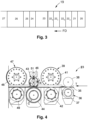
- the converting machine 19 comprises several units aligned along the longitudinal axis and the driving direction FD of the sheets.
- a plurality of crease lines 11, 12 are needed. Different format and models of folding boxes 1' have different number and positions of the crease lines 11, 12.
- the illustrated intermediate blank 1 and the configuration of the cuts and crease lines are just an example of numerous different intermediate blanks 1 which can be used for producing a folding box 1' suitable for forming a three-dimensional folded box.
- Crease lines 11, 12 and their slits 13 enable to fold the blank 1 into a folding box 1' with a rectangular shape, each crease line 11, 12 defining a folding line (see figure 1 ).
- glue is typically deposited onto the flap 14 and the large left central panel 6a is thus joined to the small right central panel 7a'.
- a second slotting section 47 with a fourth pair of shafts positioned one above the other, is mounted downstream of the creasing section 43.
- the upper shaft of the second slotting section 47 is provided with a disc equipped with knives 48 and the lower shaft is provided with a lower counter blade 49.
- the second slotting section 47 cuts the slits 13 positioned at the front of the blank 1.
- the lower and upper pre-creasers 37 and 38 as well as the lower and upper creasers 44 and 46 are creasing devices with creasing tools 53. Accordingly, the creasing tools 53 are mounted in the creasing section 43 on the shafts, which function as a support for the respective creasing tool 53. It is also possible to arrange the precreaser 37 and the creaser 44 either above or below the fibrous substrate 35.
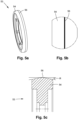
- the crease-line forming portion 56 is a raised line extending around the circumference of the creasing tool 53.
- the crease-line forming portion 56 will create a central portion of the crease line.
- the central portion of the crease line defines the priority folding line, which is the precise location for the fold.
- the peripheral deformation portion 59 distributes the compression force from the creasing tool 53 over the fibrous substrate 35 in a gradual manner in a direction towards the crease-line forming portion 56. Hence, the compression on the fibrous substrate 35 is increased from the peripheral deformation 59 portion and thus concentrated towards the crease-line forming portion 56 of the creasing tool 53.
- the peripheral deformation portion 59 is a discrete protruding pattern extending from the base surface 57.
- the peripheral deformation portion 59 can be designed to protrude between 0,5 and 1,6 mm from the base surface 57.
- the peripheral deformation portion 59 is provided with a plurality of transverse surface areas 58.
- the transverse surface areas 58 have a perpendicular length of d 2 (see figure 8b ) in relation to the longitudinal direction L of the central crease-line forming portion 56.
- the transverse surface areas 58 extend in a transverse direction in relation to a longitudinal direction L of the central crease-line forming portion 56 and in relation to a central axis M of the creasing tool 53. These transverse surface areas 58 can be linearly shaped.
- the transverse surface areas 58 can be shaped as chevrons 58, or as fishbones when seen together with the crease-line forming portion 56.
- the crease lines 11, 12 formed on the fibrous substrate 35 comprise a main crease line portion which is the center part of the crease lines 11, 12 and is provided by the crease-line forming portion 56. If the crease lines 11, 12 are provided by a main creasing tool 53, the main crease-line portion corresponds to the priority folding line. In another example, if the crease lines 11, 12 are provided by a precreaser, the main crease-line portion forms a main portion of a precreasing area.
- the crease lines 11, 12 are also provided with a peripheral crease-line portion, provided by the peripheral deformation portion 58.
- the proximal portions 61 of the transverse surface areas 58 on a first side of the crease-line forming portion 56 are touching the transverse surface areas 58 on a second and opposite side of the crease-line forming portion 56.
- a transverse length d 2 (see figure 8b ) of the transverse surface areas 58 is therefore advantageously selected based on the geometry of the corrugated fibrous cardboard substrate 35 and in particular the distances p1 between the flutes.
- the transverse length d 2 of the transverse surface areas 58 is selected to be equal or larger than the 50% of the peak-to-peak distance p1 between the flutes in the corrugated fibrous substrate 35.
- a distance of 100% of the peak-to-peak distance p1 can be selected. This ensures that the transverse surface areas 58 are in contact with a flute even if the creasing tool 53 is not positioned centrally in-between the flutes.
- the transverse surface areas 58 are thus configured to gradually increase and direct the deformation on the fibrous substrate 35 converge into the central main crease-line portion. Hence, the proximal portions 61 of the transverse surface areas 58 form the crease-line forming portion 56.
- the outer periphery of the curved transverse surface areas 58 is concave in relation to the outer edges 60 of the creasing tool 57. Consequently, the convex side of the transverse surface areas 58 is located closer to the central axis M than the concave side.
- the discrete segments or transverse surface areas 58 are extending in a transverse direction at an angle ⁇ in relation to the central axis M and in the direction of rotation of the disc R.
- the angle ⁇ is less than 90 degrees such that the distal ends 63 of the discrete segments or transverse surface areas 58 are brought into contact with the fibrous substrate 1 before the proximal portions 61 of the discrete transverse surface areas 58.
- the transverse surface areas 58 on the first side of the crease-line forming portion 56 and the transverse surface areas of the second side of the crease-line forming portion 56 cooperate such that even if the transverse surface areas 58 are arranged in a discrete manner, there is a continuous transverse component in the peripheral deformation portion 59 that is applying a pressure on the flutes 10 in the fibrous substrate 35. This ensures a continuous compression force onto the fibrous substrate 35 in the transverse direction and a dense arrangement of the transverse surface areas 58 on the outer surface of the creasing tool 53.
- the transverse surface areas 58 may be placed equidistant on the outer surface of the creasing tool 53, wherein the distal ends 63 the transverse surface areas 58 are spaced apart at a distance d 4 . If the transverse surface areas 58 are all of the same size, the distance d 4 between the proximal portions 61 is the same (i.e. constant) around the outer circumference of the creasing tool 53.
- the creasing tool 53 is arranged in a similar way as in the first embodiment, but additionally comprises a continuous annular ridge 66 in the crease-line forming portion 56.
- the annular ridge 66 has a linear and straight shape extending along the central axis M. The annular ridge 66 thus extends around the outer circumference of the creasing disc 53.
- the annular ridge 66 is arranged parallel to the edge 60 of the creasing tool 53.
- the annular ridge 66 is placed at a distance d 1 , from the edge 60 which is preferably selected to correspond to about 50% of the total width W of the creasing tool 53, such that the midrib 56 is positioned in the center of the creasing tool 53.
- the transverse surface areas 58 whose extension direction E extend from the annular ridge 66 towards the edge 60 of the creasing tool 53 are in contact with the annular creasing ridge 66.
- the annular ridge 66 may preferably protrude further from the base surface 57 than the proximal portions 61 of the transverse surface areas 58.
- the annular creasing ridge 66 provides a sharper protrusion from the outer surface of the creasing tool 53 compared to the creasing tool of the first embodiment, therefore further increasing the sharpness of crease lines 11, 12 formed by the creasing tool 53.
- the transverse surface areas 58 still provide a gradually increasing deformation on the fibrous substrate 35 surface to prevent the fibrous substrate 1 from being teared.
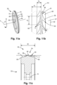
- FIG. 10a to 10c a fourth embodiment of the creasing tool 53 is shown.
- the creasing tool 53 is arranged similarly to the first embodiment, but the crease-line forming portion 56 and the peripheral deformation portion 59 are formed from a single continuous segment.
- the transverse surface areas 58 in the peripheral deformation portion 59 are provided with a proximal portion 61 that is wider than the distal portion 63.
- the proximal portions 61 of preceding and subsequent transverse surface areas 58 merge. Additionally, the proximal portions 61 of the opposite transverse surface areas 58 merge over the central axis M.
- This type of creasing tool 53 can advantageously be used for performing pre-creasing operations as it prepares a fold in the fibrous substrate 35 for a subsequent and sharper ridge of a creasing tool 53.
- the slope angle ⁇ describes the inclination of the peripheral deformation portion 59 from a coalesced midrib 56 to the distal end portions 61. and in relation to the rotation axis Xr.
- the proximal portions 61 of the transverse surface areas 58 are broadened in a direction towards the crease-line forming portion 56.
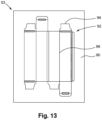
- the die 53 comprises a die board 90 provided with a pattern of cutting edges 94 and creasing edges 96.
- the cutting edges 94 are located in the periphery of the die board 90 and will define the outer contour of the intermediate blank 1.
Landscapes
- Engineering & Computer Science (AREA)
- Mechanical Engineering (AREA)
- Machines For Manufacturing Corrugated Board In Mechanical Paper-Making Processes (AREA)
- Making Paper Articles (AREA)
Applications Claiming Priority (2)
| Application Number | Priority Date | Filing Date | Title |
|---|---|---|---|
| EP20315265 | 2020-05-26 | ||
| PCT/EP2021/063987 WO2021239783A1 (en) | 2020-05-26 | 2021-05-26 | Creasing tool and method of creating crease lines |
Publications (3)
| Publication Number | Publication Date |
|---|---|
| EP4157625A1 EP4157625A1 (en) | 2023-04-05 |
| EP4157625C0 EP4157625C0 (en) | 2025-03-05 |
| EP4157625B1 true EP4157625B1 (en) | 2025-03-05 |
Family
ID=71575313
Family Applications (1)
| Application Number | Title | Priority Date | Filing Date |
|---|---|---|---|
| EP21728891.9A Active EP4157625B1 (en) | 2020-05-26 | 2021-05-26 | Creasing tool and method of creating crease lines |
Country Status (8)
| Country | Link |
|---|---|
| US (1) | US12162241B2 (pl) |
| EP (1) | EP4157625B1 (pl) |
| JP (1) | JP7621386B2 (pl) |
| KR (2) | KR20240161229A (pl) |
| CN (1) | CN115916519B (pl) |
| ES (1) | ES3015012T3 (pl) |
| PL (1) | PL4157625T3 (pl) |
| WO (1) | WO2021239783A1 (pl) |
Families Citing this family (3)
| Publication number | Priority date | Publication date | Assignee | Title |
|---|---|---|---|---|
| EP4524071B1 (en) | 2023-09-14 | 2026-02-18 | Bobst Mex Sa | Feeder module for a converting machine |
| DE102024107249A1 (de) * | 2024-03-14 | 2025-09-18 | Knüppel Verpackung GmbH & Co. KG | Verfahren und Vorrichtung zur Verringerung der Biegesteifigkeit von Wellpappe und flexibilisierte Wellpappe |
| WO2025262219A1 (en) * | 2024-06-20 | 2025-12-26 | Bobst Lyon | Slotter module for a converting machine |
Family Cites Families (15)
| Publication number | Priority date | Publication date | Assignee | Title |
|---|---|---|---|---|
| US2223503A (en) * | 1939-07-07 | 1940-12-03 | Wilber E Bowersock | Scoring method and tool |
| JPS5927263A (ja) * | 1982-08-06 | 1984-02-13 | Mitsubishi Heavy Ind Ltd | 段ボ−ルの走行速度計測装置 |
| JP3089398B2 (ja) | 1996-12-20 | 2000-09-18 | 旭精密株式会社 | 測量機械の傾き自動補正装置に用いる水準器 |
| JP3165659B2 (ja) | 1997-06-24 | 2001-05-14 | 日本ダイスチール株式会社 | 段ボール紙の折曲げ用罫線および罫入れ装置 |
| JP2001205718A (ja) * | 2000-01-31 | 2001-07-31 | Tomoku Co Ltd | 罫線形成ジグ |
| JP3089398U (ja) * | 2002-04-18 | 2002-10-25 | 株式会社坂本製作所 | 段ボールを折曲げる際の折曲用罫線補強部材 |
| JP4060649B2 (ja) * | 2002-05-20 | 2008-03-12 | 日本ダイスチール株式会社 | 罫入れ型および罫入れ装置 |
| JP2004148763A (ja) * | 2002-10-31 | 2004-05-27 | Sakamoto Seisakusho:Kk | 段ボール等を折曲げる際の折曲用罫線補強部材 |
| JP4060692B2 (ja) * | 2002-11-22 | 2008-03-12 | レンゴー株式会社 | 罫入れ装置 |
| ITUD20110047A1 (it) * | 2011-03-30 | 2012-10-01 | Panotec Srl | Dispositivo di cordonatura e relativo metodo |
| WO2016027498A1 (ja) * | 2014-08-18 | 2016-02-25 | ダイペックス株式会社 | 押罫部材、罫入れ用型板および罫入れ装置 |
| CN106457728B (zh) * | 2014-12-17 | 2019-04-16 | 迪佩克斯株式会社 | 折痕按压部件 |
| WO2016176271A1 (en) * | 2015-04-29 | 2016-11-03 | Packsize Llc | Profiling of packaging systems |
| US11541622B2 (en) | 2017-07-06 | 2023-01-03 | Bobst Mex Sa | Creasing machine, creasing cylinder for the creasing machine and method for creasing sheets |
| US11701854B2 (en) * | 2019-03-14 | 2023-07-18 | Packsize Llc | Packaging machine and systems |
-
2021
- 2021-05-26 US US17/999,416 patent/US12162241B2/en active Active
- 2021-05-26 PL PL21728891.9T patent/PL4157625T3/pl unknown
- 2021-05-26 JP JP2022573566A patent/JP7621386B2/ja active Active
- 2021-05-26 KR KR1020247036637A patent/KR20240161229A/ko active Pending
- 2021-05-26 WO PCT/EP2021/063987 patent/WO2021239783A1/en not_active Ceased
- 2021-05-26 EP EP21728891.9A patent/EP4157625B1/en active Active
- 2021-05-26 ES ES21728891T patent/ES3015012T3/es active Active
- 2021-05-26 CN CN202180048424.3A patent/CN115916519B/zh active Active
- 2021-05-26 KR KR1020227044480A patent/KR20230012608A/ko not_active Ceased
Also Published As
| Publication number | Publication date |
|---|---|
| EP4157625C0 (en) | 2025-03-05 |
| EP4157625A1 (en) | 2023-04-05 |
| KR20230012608A (ko) | 2023-01-26 |
| US20230234320A1 (en) | 2023-07-27 |
| US12162241B2 (en) | 2024-12-10 |
| CN115916519A (zh) | 2023-04-04 |
| ES3015012T3 (en) | 2025-04-28 |
| JP7621386B2 (ja) | 2025-01-24 |
| JP2023527551A (ja) | 2023-06-29 |
| KR20240161229A (ko) | 2024-11-12 |
| PL4157625T3 (pl) | 2025-04-28 |
| WO2021239783A1 (en) | 2021-12-02 |
| CN115916519B (zh) | 2025-07-18 |
Similar Documents
| Publication | Publication Date | Title |
|---|---|---|
| EP4157625B1 (en) | Creasing tool and method of creating crease lines | |
| US11141947B2 (en) | Device for processing a plate element, processing unit and packaging production machine | |
| CN107428108A (zh) | 瓦楞纸箱、瓦楞纸片的折线形成方法、以及瓦楞纸片的折线形成装置 | |
| US5873807A (en) | Scoring assembly | |
| US12325206B2 (en) | Unit for forming a plate element for manufacturing folding boxes | |
| JP6295336B2 (ja) | ブランクの供給装置及びそれを用いたブランクの供給方法 | |
| GB2301316A (en) | Dies or rollers for creasing corrugated boards | |
| US20150119221A1 (en) | Apparatus and method for forming a bending crease in corrugated paperboard | |
| JPH07132569A (ja) | タブ切断装置 | |
| GB2242151A (en) | Precrush tool for corrugated board slotter head | |
| US6537189B1 (en) | Device for stamping groove lines on corrugated board | |
| JP7128722B2 (ja) | 胴部分割用ミシン目入り段ボール箱、および段ボール分割用のミシン目形成方法 | |
| RU2391213C2 (ru) | Способ и устройство для биговки картона | |
| JP7781037B2 (ja) | 段ボールシートの不良検出装置および方法並びに製函機 | |
| CN110757583A (zh) | 一种印刷纸板的连接结构及其模切装置和应用 | |
| JPH1110754A (ja) | 罫入り段ボールシートおよび罫入れ装置 | |
| KR102722933B1 (ko) | 골판지 상자 제조용 슬로팅 위상 자동 조절장치 | |
| JPH0629827U (ja) | 段ボールシートの折り目形成用罫型 | |
| US12441507B2 (en) | Skip slot box blanks, boxes and methods of forming the same | |
| US20240316893A1 (en) | Corrugated Pizza Box and Method for Production of Same | |
| JP7484592B2 (ja) | パーテーション用ブランクシートおよびパーテーション用ブランクシートの製造方法 | |
| CN120435380A (zh) | 用于转换机的翼片切割装置 | |
| JP2001113613A (ja) | 罫入れ装置 | |
| JP2019059033A (ja) | 押罫部材 | |
| JPH10272709A (ja) | 罫線装置 |
Legal Events
| Date | Code | Title | Description |
|---|---|---|---|
| STAA | Information on the status of an ep patent application or granted ep patent |
Free format text: STATUS: UNKNOWN |
|
| STAA | Information on the status of an ep patent application or granted ep patent |
Free format text: STATUS: THE INTERNATIONAL PUBLICATION HAS BEEN MADE |
|
| PUAI | Public reference made under article 153(3) epc to a published international application that has entered the european phase |
Free format text: ORIGINAL CODE: 0009012 |
|
| STAA | Information on the status of an ep patent application or granted ep patent |
Free format text: STATUS: REQUEST FOR EXAMINATION WAS MADE |
|
| 17P | Request for examination filed |
Effective date: 20221115 |
|
| AK | Designated contracting states |
Kind code of ref document: A1 Designated state(s): AL AT BE BG CH CY CZ DE DK EE ES FI FR GB GR HR HU IE IS IT LI LT LU LV MC MK MT NL NO PL PT RO RS SE SI SK SM TR |
|
| DAV | Request for validation of the european patent (deleted) | ||
| DAX | Request for extension of the european patent (deleted) | ||
| GRAP | Despatch of communication of intention to grant a patent |
Free format text: ORIGINAL CODE: EPIDOSNIGR1 |
|
| STAA | Information on the status of an ep patent application or granted ep patent |
Free format text: STATUS: GRANT OF PATENT IS INTENDED |
|
| INTG | Intention to grant announced |
Effective date: 20241118 |
|
| GRAS | Grant fee paid |
Free format text: ORIGINAL CODE: EPIDOSNIGR3 |
|
| GRAA | (expected) grant |
Free format text: ORIGINAL CODE: 0009210 |
|
| STAA | Information on the status of an ep patent application or granted ep patent |
Free format text: STATUS: THE PATENT HAS BEEN GRANTED |
|
| AK | Designated contracting states |
Kind code of ref document: B1 Designated state(s): AL AT BE BG CH CY CZ DE DK EE ES FI FR GB GR HR HU IE IS IT LI LT LU LV MC MK MT NL NO PL PT RO RS SE SI SK SM TR |
|
| REG | Reference to a national code |
Ref country code: GB Ref legal event code: FG4D |
|
| REG | Reference to a national code |
Ref country code: CH Ref legal event code: EP |
|
| REG | Reference to a national code |
Ref country code: IE Ref legal event code: FG4D |
|
| REG | Reference to a national code |
Ref country code: DE Ref legal event code: R096 Ref document number: 602021027156 Country of ref document: DE |
|
| U01 | Request for unitary effect filed |
Effective date: 20250312 |
|
| U07 | Unitary effect registered |
Designated state(s): AT BE BG DE DK EE FI FR IT LT LU LV MT NL PT RO SE SI Effective date: 20250320 |
|
| U20 | Renewal fee for the european patent with unitary effect paid |
Year of fee payment: 5 Effective date: 20250505 |
|
| PG25 | Lapsed in a contracting state [announced via postgrant information from national office to epo] |
Ref country code: RS Free format text: LAPSE BECAUSE OF FAILURE TO SUBMIT A TRANSLATION OF THE DESCRIPTION OR TO PAY THE FEE WITHIN THE PRESCRIBED TIME-LIMIT Effective date: 20250605 |
|
| PGFP | Annual fee paid to national office [announced via postgrant information from national office to epo] |
Ref country code: PL Payment date: 20250402 Year of fee payment: 5 |
|
| PGFP | Annual fee paid to national office [announced via postgrant information from national office to epo] |
Ref country code: ES Payment date: 20250605 Year of fee payment: 5 |
|
| PG25 | Lapsed in a contracting state [announced via postgrant information from national office to epo] |
Ref country code: NO Free format text: LAPSE BECAUSE OF FAILURE TO SUBMIT A TRANSLATION OF THE DESCRIPTION OR TO PAY THE FEE WITHIN THE PRESCRIBED TIME-LIMIT Effective date: 20250605 |
|
| PG25 | Lapsed in a contracting state [announced via postgrant information from national office to epo] |
Ref country code: HR Free format text: LAPSE BECAUSE OF FAILURE TO SUBMIT A TRANSLATION OF THE DESCRIPTION OR TO PAY THE FEE WITHIN THE PRESCRIBED TIME-LIMIT Effective date: 20250305 |
|
| PG25 | Lapsed in a contracting state [announced via postgrant information from national office to epo] |
Ref country code: GR Free format text: LAPSE BECAUSE OF FAILURE TO SUBMIT A TRANSLATION OF THE DESCRIPTION OR TO PAY THE FEE WITHIN THE PRESCRIBED TIME-LIMIT Effective date: 20250606 |
|
| PGFP | Annual fee paid to national office [announced via postgrant information from national office to epo] |
Ref country code: CH Payment date: 20250601 Year of fee payment: 5 |
|
| PG25 | Lapsed in a contracting state [announced via postgrant information from national office to epo] |
Ref country code: SM Free format text: LAPSE BECAUSE OF FAILURE TO SUBMIT A TRANSLATION OF THE DESCRIPTION OR TO PAY THE FEE WITHIN THE PRESCRIBED TIME-LIMIT Effective date: 20250305 |
|
| PG25 | Lapsed in a contracting state [announced via postgrant information from national office to epo] |
Ref country code: CZ Free format text: LAPSE BECAUSE OF FAILURE TO SUBMIT A TRANSLATION OF THE DESCRIPTION OR TO PAY THE FEE WITHIN THE PRESCRIBED TIME-LIMIT Effective date: 20250305 |
|
| PG25 | Lapsed in a contracting state [announced via postgrant information from national office to epo] |
Ref country code: SK Free format text: LAPSE BECAUSE OF FAILURE TO SUBMIT A TRANSLATION OF THE DESCRIPTION OR TO PAY THE FEE WITHIN THE PRESCRIBED TIME-LIMIT Effective date: 20250305 |
|
| PG25 | Lapsed in a contracting state [announced via postgrant information from national office to epo] |
Ref country code: IS Free format text: LAPSE BECAUSE OF FAILURE TO SUBMIT A TRANSLATION OF THE DESCRIPTION OR TO PAY THE FEE WITHIN THE PRESCRIBED TIME-LIMIT Effective date: 20250705 |
|
| PLBE | No opposition filed within time limit |
Free format text: ORIGINAL CODE: 0009261 |
|
| STAA | Information on the status of an ep patent application or granted ep patent |
Free format text: STATUS: NO OPPOSITION FILED WITHIN TIME LIMIT |
|
| REG | Reference to a national code |
Ref country code: CH Ref legal event code: L10 Free format text: ST27 STATUS EVENT CODE: U-0-0-L10-L00 (AS PROVIDED BY THE NATIONAL OFFICE) Effective date: 20260114 |
|
| PG25 | Lapsed in a contracting state [announced via postgrant information from national office to epo] |
Ref country code: MC Free format text: LAPSE BECAUSE OF FAILURE TO SUBMIT A TRANSLATION OF THE DESCRIPTION OR TO PAY THE FEE WITHIN THE PRESCRIBED TIME-LIMIT Effective date: 20250305 |
|
| 26N | No opposition filed |
Effective date: 20251208 |