EP4149797B1 - Führersitz für ein schienenfahrzeug - Google Patents
Führersitz für ein schienenfahrzeug Download PDFInfo
- Publication number
- EP4149797B1 EP4149797B1 EP21731699.1A EP21731699A EP4149797B1 EP 4149797 B1 EP4149797 B1 EP 4149797B1 EP 21731699 A EP21731699 A EP 21731699A EP 4149797 B1 EP4149797 B1 EP 4149797B1
- Authority
- EP
- European Patent Office
- Prior art keywords
- seat
- case
- compressed air
- driver
- carrier
- Prior art date
- Legal status (The legal status is an assumption and is not a legal conclusion. Google has not performed a legal analysis and makes no representation as to the accuracy of the status listed.)
- Active
Links
Images
Classifications
-
- B—PERFORMING OPERATIONS; TRANSPORTING
- B60—VEHICLES IN GENERAL
- B60N—SEATS SPECIALLY ADAPTED FOR VEHICLES; VEHICLE PASSENGER ACCOMMODATION NOT OTHERWISE PROVIDED FOR
- B60N2/00—Seats specially adapted for vehicles; Arrangement or mounting of seats in vehicles
- B60N2/50—Seat suspension devices
- B60N2/52—Seat suspension devices using fluid means
- B60N2/525—Seat suspension devices using fluid means using gas
-
- B—PERFORMING OPERATIONS; TRANSPORTING
- B60—VEHICLES IN GENERAL
- B60N—SEATS SPECIALLY ADAPTED FOR VEHICLES; VEHICLE PASSENGER ACCOMMODATION NOT OTHERWISE PROVIDED FOR
- B60N2/00—Seats specially adapted for vehicles; Arrangement or mounting of seats in vehicles
- B60N2/02—Seats specially adapted for vehicles; Arrangement or mounting of seats in vehicles the seat or part thereof being movable, e.g. adjustable
- B60N2/04—Seats specially adapted for vehicles; Arrangement or mounting of seats in vehicles the seat or part thereof being movable, e.g. adjustable the whole seat being movable
- B60N2/06—Seats specially adapted for vehicles; Arrangement or mounting of seats in vehicles the seat or part thereof being movable, e.g. adjustable the whole seat being movable slidable
-
- B—PERFORMING OPERATIONS; TRANSPORTING
- B60—VEHICLES IN GENERAL
- B60N—SEATS SPECIALLY ADAPTED FOR VEHICLES; VEHICLE PASSENGER ACCOMMODATION NOT OTHERWISE PROVIDED FOR
- B60N2/00—Seats specially adapted for vehicles; Arrangement or mounting of seats in vehicles
- B60N2/02—Seats specially adapted for vehicles; Arrangement or mounting of seats in vehicles the seat or part thereof being movable, e.g. adjustable
- B60N2/04—Seats specially adapted for vehicles; Arrangement or mounting of seats in vehicles the seat or part thereof being movable, e.g. adjustable the whole seat being movable
- B60N2/14—Seats specially adapted for vehicles; Arrangement or mounting of seats in vehicles the seat or part thereof being movable, e.g. adjustable the whole seat being movable rotatable, e.g. to permit easy access
-
- B—PERFORMING OPERATIONS; TRANSPORTING
- B60—VEHICLES IN GENERAL
- B60N—SEATS SPECIALLY ADAPTED FOR VEHICLES; VEHICLE PASSENGER ACCOMMODATION NOT OTHERWISE PROVIDED FOR
- B60N2/00—Seats specially adapted for vehicles; Arrangement or mounting of seats in vehicles
- B60N2/50—Seat suspension devices
- B60N2/502—Seat suspension devices attached to the base of the seat
-
- B—PERFORMING OPERATIONS; TRANSPORTING
- B60—VEHICLES IN GENERAL
- B60N—SEATS SPECIALLY ADAPTED FOR VEHICLES; VEHICLE PASSENGER ACCOMMODATION NOT OTHERWISE PROVIDED FOR
- B60N2/00—Seats specially adapted for vehicles; Arrangement or mounting of seats in vehicles
- B60N2/50—Seat suspension devices
- B60N2/505—Adjustable suspension including height adjustment
-
- B—PERFORMING OPERATIONS; TRANSPORTING
- B61—RAILWAYS
- B61C—LOCOMOTIVES; MOTOR RAILCARS
- B61C17/00—Arrangement or disposition of parts; Details or accessories not otherwise provided for; Use of control gear and control systems
- B61C17/04—Arrangement or disposition of driving cabins, footplates or engine rooms; Ventilation thereof
-
- B—PERFORMING OPERATIONS; TRANSPORTING
- B61—RAILWAYS
- B61D—BODY DETAILS OR KINDS OF RAILWAY VEHICLES
- B61D33/00—Seats
- B61D33/0057—Seats characterised by their mounting in vehicles
- B61D33/0078—Seats characterised by their mounting in vehicles adjustably mounted
- B61D33/0085—Seats characterised by their mounting in vehicles adjustably mounted rotatably
Definitions
- the invention relates to a driver's seat for a rail vehicle, in particular a locomotive driver's seat.
- More complex driver's seats are usually pneumatically supported and offer significantly greater comfort as well as additional functionalities (e.g. they provide lumbar support or support for the rail vehicle driver when he or she adjusts the seat).
- Such compressed air-assisted driver's seats have a corresponding compressed air supply, in which a compressed air hose is usually guided inside a vertical, hollow steel tube.
- the actual seat for the rail vehicle driver is attached to this steel tube (e.g. via a screw connection or a welded connection).
- the compressed air hose is not rigid but flexible and is guided in such a way that rotational movements of the seat in a horizontal plane are possible.
- the compressed air hose is therefore located in the area of the seat's axis of rotation, so that the seat can be rotated left and right around the axis of rotation in a horizontal plane without any problems.
- the compressed air hose is advantageously only twisted slightly here.
- the flexible compressed air hose also allows a small forward-backward movement of the seat, which is necessary for seat adjustment to the rail vehicle driver.
- an alternative solution for an off-center compressed air guide is to arrange a single flexible hose with a large loop in such a way that movements are possible. This loop is then located between the fixed and the rotating or sliding seat part and typically protrudes well above it.
- a vehicle which has a driver's cab with a driver's cab floor and a seat console which is arranged so as to be movable relative to the driver's cab floor and has a tubular cable guide.
- the invention relates to a driver's seat for a rail vehicle, in particular a locomotive driver's seat, with a seat, a frame, a carrier, a fastening unit and with a compressed air line that ensures compressed air-supported functionalities of the driver's seat.
- the frame that supports the seat is rotatably mounted and connected to a first end of the carrier so that the seat can be rotated about an axis of the carrier.
- a second end of the carrier is connected to the fastening unit in order to fasten the carrier in a control station of a rail vehicle.
- the compressed air line is arranged in such a way that the compressed air-supported functionalities of the seat are guaranteed.
- the compressed air line is implemented in a first region as a number of partial windings which at least partially surround the carrier radially at a predetermined distance.
- the partial windings are designed and attached in such a way that a rotational movement of the seat causes a change in the distance of the partial windings from the carrier.
- the partial turns of the compressed air line form a spiral which is wound around the carrier at a predetermined distance from the carrier.
- the compressed air line is implemented in a second area as at least one partial loop.
- the at least one partial loop is designed and secured in such a way that a translational movement of the seat causes a change in the shape of the partial loop.
- the translational movement which preferably takes place in a horizontal plane, causes a change in the laying shape of the compressed air line and results in a compression or stretching of the partial loop.
- the partial windings surround the carrier radially.
- the rotational movement of the seat which preferably takes place in a horizontal plane, causes a change in the laying shape of the compressed air line and results in a change in the radius of the partial windings.
- a pneumatic suspension and/or a pneumatic seat adjustment is arranged between the frame and the seat, to which the compressed air line is fed in order to realize or ensure the pneumatic functionality.
- the carrier is designed as a tube or as a profile which is arranged essentially vertically between the fastening unit and the frame.
- the first region of the compressed air line is connected at its first end to the fastening unit and at its second end to the frame in order to enable the distance or radius change of the partial turns.
- the second region of the compressed air line is connected at its first end to the seat and/or to the pneumatic suspension and/or to the pneumatic seat adjustment, while its second end is connected to the frame in order to enable the change in shape of the partial loop.
- the partial windings are made of an elastic, rigid material, preferably polyamide or similar.
- At least one partial loop is made of a flexible hose material, for example it is realized as a fabric-coated rubber hose.
- the partial loop is dimensioned such that the partial loop has a mechanically relaxed shape when the seat is in the middle position, which changes during a translational movement of the seat, namely is either stretched or compressed.
- the second end of the support is arranged opposite the first end of the support.
- the seat is preferably rotated about a longitudinal axis of the support.
- a rotation of the seat in a first direction causes an increase in the distance or radius of the partial turns
- a rotation of the seat in an opposite second direction causes a reduction in the radius of the partial turns
- a translational movement of the seat in a first direction causes an extension of the at least one partial loop
- a translational movement of the seat in an opposite second direction causes a compression of the at least one partial loop
- a number of partial turns or turns required for functionality and the associated nominal radius are coordinated with a permissible, specified angle of rotation of the seat and with a specified diameter of the carrier.
- the present invention achieves a long-lasting driver's seat design and thus ensures a high quality standard of the seat construction.
- the present invention avoids the disadvantageous undefined deformation of the flexible compressed air hose known from the prior art, which occurs in particular due to a superposition of the rotational and sliding movements.
- the present invention prevents chafing or kinking of the compressed air line.
- the present invention enables the compressed air supply to be separated into a portion for the seat rotation movement and a portion for the seat sliding movement.
- the present invention makes it possible to optimize the respective material of the compressed air line and thus its mechanical properties to the movement profile.
- the present invention divides the compressed air supply into two functionalities or components.
- a first part is intended exclusively for compensating the rotational movement of the seat, while a second part is intended exclusively for compensating the translational movement of the seat.
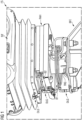
- FIG 1 shows an embodiment of the driver's seat FS according to the invention.
- the driver's seat FS includes compressed air-supported functionalities that are functionally ensured or implemented via a compressed air line DLG, which is part of the driver's seat FS.
- the driver's seat FS has a seat SIT, a frame RAH, a carrier TRG and a fastening unit BFE.
- the seat SIT is connected to a first end of the support TRG via the frame RAH, which supports the seat SIT.
- a second end of the support TRG is connected to the fastening unit BFE.
- the seat SIT is designed for use by a rail vehicle driver and is mounted so that it can rotate around an axis of the support TRG.
- the fastening unit BFE is designed for fastening the carrier TRG in a control station of the rail vehicle (not shown in detail here).
- the compressed air line DLG is realized in a first region B1 as a number of partial turns which radially encircle the carrier TRG.
- the partial windings are designed and fastened in such a way that a rotational movement of the seat SIT causes a change in the radius of the partial winding.
- the change in radius compensates for the rotational movement of the SIT seat.
- the compressed air line DLG is implemented in a second area B2 as at least one partial loop.
- This partial loop is designed and attached in such a way that a translational movement of the seat SIT is compensated by a change in the shape of the partial loop.
- the frame RAH which supports the seat SIT, is pivotally connected to the first end of the support TRG.
- the second end of the support TRG is arranged opposite the first end of the support TRG.
- the support TRG is designed here as a tube that is arranged essentially vertically between the fastening unit BFE and the frame RAH.
- a pneumatic suspension and/or a pneumatic seat adjustment is arranged, to which the compressed air line DLG is supplied to realize the pneumatic functionality.
- the first section B1 of the compressed air line DLG (with the partial windings) is connected at its first end to the fastening unit BFE and at its second end to the frame RAH. This fixes it in such a way that the radius change of the partial windings described above is possible.
- the second region B2 of the compressed air line (with the at least one partial loop) is connected at its first end to the seat SIT or to the pneumatic suspension and/or to the pneumatic seat adjustment, while its second end is connected to the frame RAH. It is thereby fixed in such a way that the change in shape of the partial loop described above is possible.
- the partial winding is made of an elastic, rigid material, for example polyamide or similar.
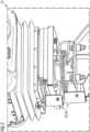
- FIG 2 shows with reference to FIG 1 an advantageous development of the driver's seat according to the invention.
- additional protective plates SCHB are provided.
Landscapes
- Engineering & Computer Science (AREA)
- Mechanical Engineering (AREA)
- Transportation (AREA)
- Aviation & Aerospace Engineering (AREA)
- Automation & Control Theory (AREA)
- Seats For Vehicles (AREA)
Description
- Die Erfindung betrifft einen Führersitz für ein Schienenfahrzeug, insbesondere einen Lokführersitz.
- Für Schienenfahrzeuge sind verschiedenste Führersitze mit unterschiedlichen Funktionalitäten bekannt.
- Einfachere bzw. billigere Schienenfahrzeug-Führersitze besitzen meist einen mäßigen Federungskomfort, der mittels mechanischer Federung realisiert ist.
- Aufgrund der Kosten wird bei diesen Führersitzen auch auf eine pneumatische und/oder elektrische Unterstützung zum ergonomischen Einstellen des Führersitzes an die Bedürfnisse des Schienenfahrzeug-Führers verzichtet.
- Aufwendigere Führersitze sind meist druckluftunterstützt und besitzen einen wesentlich höheren Komfort sowie zusätzliche Funktionalitäten (z.B. stellen diese eine Lordose-Stütze oder eine Unterstützung des Schienenfahrzeug-Führers bei einer von ihm vorgenommenen Sitzverstellung bereit).
- Derartige druckluftunterstützte Führersitze weisen eine entsprechende Druckluftversorgung auf, bei der üblicherweise ein Druckluftschlauch im Inneren eines vertikalen, hohlen Stahlrohres geführt ist. Auf diesem Stahlrohr ist der eigentliche Sitz für den Schienenfahrzeug-Führer befestigt (z.B. über eine Schraubverbindung oder über eine Schweißverbindung).
- Der Druckluftschlauch ist dabei nicht starr, sondern flexibel ausgeführt und ist derart geführt, dass Drehbewegungen des Sitzes in horizontaler Ebene ermöglicht werden.
- Der Druckluftschlauch befindet sich dadurch im Bereich der Drehachse des Sitzes, so dass eine in horizontaler Ebene erfolgende Rechts-Links-Drehung des Sitzes um die Drehachse problemlos möglich ist. Vorteilhaft wird hier der Druckluftschlauch lediglich geringfügig verdreht.
- Als weiteren Vorteil erlaubt der flexible Druckluftschlauch auch in geringem Umfang eine Vorwärts-Rückwärts-Bewegung des Sitzes, die durch eine Sitz-Anpassung an den Schienenfahrzeug-Führer notwendig wird.
- Nachteilig werden bei diesem Konzept relativ schnell Grenzen bezüglich möglicher Bewegungswege (maximale Rotationswinkel bzw. maximale Verschiebewege) erreicht.
- Darüber hinaus ist das beschriebene Konzept nicht für alle denkbaren Konstellationen geeignet. Befindet sich unter dem Sitz beispielsweise eine Lagerstelle des Sitzes, muss auf eine hohle Achse und damit auf die mittige Schlauchführung verzichtet werden.
- Eine alternative Lösung für eine außermittige Druckluftführung besteht gemäß dem Stand der Technik darin, einen einzigen flexiblen Schlauch mit einer großen Schlaufe derart anzuordnen, dass Bewegungen ermöglicht werden. Diese Schlaufe befindet sich dann zwischen dem festen und dem dreh- bzw. verschiebbaren Sitzanteil und steht dort typischerweise weit über.
- Dadurch besteht die Gefahr einer Beschädigung des Schlauches beim Vorbeigehen einer Person oder beim Drehen des Sitzes.
- Aus der Druckschrift
EP 2374654 A1 ist ein Fahrzeug bekannt, das ein Fahrerhaus mit einem Fahrerhausboden und eine relativ zum Fahrerhausboden bewegbar angeordnete Sitzkonsole mit einer schlauchförmigen Leitungsführung aufweist. - Aus der Druckschrift
US 20040051023 A1 ist eine Sitzanordnung für ein Kraftfahrzeug mit einem Luftfederaufhängungssystem bekannt. - Es ist daher die Aufgabe der vorliegenden Erfindung, einen verbesserten Führersitz für ein Schienenfahrzeug bereitzustellen, mit dem die oben genannten Nachteile kostengünstig überwunden werden.
- Diese Aufgabe wird durch die Merkmale des Anspruchs 1 gelöst. Vorteilhafte Weiterbildungen sind in den jeweiligen abhängigen Ansprüchen angegeben.
- Die Erfindung betrifft einen Führersitz für ein Schienenfahrzeug, insbesondere einen Lokführersitz, mit einem Sitz, einem Rahmen, einem Träger, einer Befestigungseinheit und mit einer Druckluftleitung, die druckluftunterstützte Funktionalitäten des Führersitzes gewährleistet. Der Rahmen, der den Sitz trägt, ist drehbar gelagert mit einem ersten Ende des Trägers verbunden, so dass der Sitz um eine Achse des Trägers herum drehbar ist. Ein zweites Ende des Trägers ist mit der Befestigungseinheit verbunden, um den Träger in einem Leitstand eines Schienenfahrzeugs zu befestigen.
- Die Druckluftleitung ist derart angeordnet, dass die druckluftunterstützten Funktionalitäten des Sitzes gewährleistet sind.
- Die Druckluftleitung ist in einem ersten Bereich als eine Anzahl an Teilwindungen realisiert, die den Träger radial mit einem vorgegebenen Abstand zumindest teilweise umlaufend umfassen. Die Teilwindungen sind derart ausgebildet und befestigt, dass eine Drehbewegung des Sitzes eine Änderung des Abstands der Teilwindungen zum Träger bewirkt.
- Erfindungsgemäß bilden die Teilwindungen der Druckluftleitung eine Spirale, die um den Träger herum mit einem vorgegebenen Abstand zum Träger aufgewickelt ist.
- In einer vorteilhaften Weiterbildung ist die Druckluftleitung in einem zweiten Bereich als zumindest eine Teilschlaufe realisiert. Dabei ist die zumindest eine Teilschlaufe derart ausgebildet und befestigt, dass eine translatorische Bewegung des Sitzes eine Formänderung der Teilschlaufe bewirkt. Die translatorische Bewegung, die bevorzug in horizontaler Ebene erfolgt, bewirkt eine Änderung der Verlegungsform der Druckluftleitung und resultiert in einer Stauchung bzw. Streckung der Teilschlaufe.
- Die Teilwindungen umfassen den Träger radial umlaufend. Die Drehbewegung des Sitzes, die bevorzugt in horizontaler Ebene erfolgt, bewirkt eine Änderung der Verlegungsform der Druckluftleitung und resultiert in einer Radiusänderung der Teilwindungen.
- In einer vorteilhaften Weiterbildung ist zwischen dem Rahmen und dem Sitz eine pneumatische Federung und/oder eine pneumatische Sitzverstellung angeordnet, der die Druckluftleitung zur Realisierung bzw. Gewährleistung der pneumatischen Funktionalität zugeführt ist.
- In einer vorteilhaften Weiterbildung ist der Träger als Rohr oder als Profil ausgebildet, das im Wesentlichen vertikal stehend zwischen der Befestigungseinheit und dem Rahmen angeordnet ist.
- In einer vorteilhaften Weiterbildung ist der erste Bereich des Druckluftleitung an seinem ersten Ende mit der Befestigungseinheit und an seinem zweiten Ende mit dem Rahmen verbunden, um die Abstandsänderung bzw. Radiusänderung der Teilwindungen zu ermöglichen.
- In einer vorteilhaften Weiterbildung ist der zweite Bereich der Druckluftleitung an seinem ersten Ende mit dem Sitz und/oder mit der pneumatischen Federung und/oder mit der pneumatischen Sitzverstellung verbunden, während sein zweites Ende mit dem Rahmen verbunden ist, um die Formänderung der Teilschlaufe zu ermöglichen.
- In einer vorteilhaften Weiterbildung sind die Teilwindungen aus einem elastischen, starren Material, bevorzugt aus Polyamid oder ähnlichem, gefertigt.
- In einer vorteilhaften Weiterbildung ist die zumindest eine Teilschlaufe aus einem flexiblen Schlauchmaterial gefertigt, beispielswiese ist sie als gewebeummantelter Gummischlauch realisiert.
- In einer vorteilhaften Weiterbildung ist die Teilschlaufe derart dimensioniert, dass die Teilschlaufe bei einer Mittenstellung des Sitzes eine mechanisch entspannte Form aufweist, die sich bei einer translatorischen Bewegung des Sitzes ändert, nämlich entweder gestreckt oder gestaucht wird.
- In einer bevorzugten Weiterbildung ist das zweite Ende des Trägers gegenüberliegend zum ersten Ende des Trägers angeordnet. Die Drehung des Sitzes erfolgt bevorzugt um eine Längsachse des Trägers.
- Zusammengefasst bewirkt bei der vorliegenden Erfindung eine Rotation des Sitzes in einer ersten Richtung (z.B. im Uhrzeigersinn) eine Vergrößerung des Abstandes bzw. des Radius der Teilwindungen, während eine Rotation des Sitzes in einer dazu entgegengesetzten zweiten Richtung (z.B. entgegen dem Uhrzeigersinn) eine Verkleinerung des Radius der Teilwindungen bewirkt.
- Entsprechend bewirkt eine translatorische Bewegung des Sitzes in einer ersten Richtung (z.B. parallel zu einer Fahrtrichtung des Schienenfahrzeugs, nach vorne gerichtet) eine Streckung der zumindest einen Teilschlaufe, während eine translatorische Bewegung des Sitzes in einer dazu entgegengesetzten zweiten Richtung (z.B. parallel zu einer Fahrtrichtung des Schienenfahrzeugs, nach hinten gerichtet) eine Stauchung der zumindest einen Teilschlaufe bewirkt.
- Eine für die Funktionalität benötigte Anzahl an Teilwindungen bzw. Windungen und der zugehörige Nennradius werden abgestimmt auf einen zulässigen, vorgegebenen Rotationswinkel des Sitzes und auf einen vorgegebenen Durchmesser des Trägers.
- Durch die Wahl des Materials für die Teilwindungen bzw. für resultierende Windungen wird eine vorgegebene Form und Lage gewährleistet.
- Durch die vorliegende Erfindung wird eine langlebige Führersitz-Ausgestaltung erreicht und damit ein hoher Qualitätsanspruch der Sitz-Konstruktion sichergestellt.
- Durch die vorliegende Erfindung wird das aus dem Stand der Technik bekannte, nachteilige undefinierte Verformen des flexiblen Druckluftschlauchs vermieden, die insbesondere durch eine Überlagerung der Dreh- und Verschiebebewegung entsteht.
- Durch die vorliegende Erfindung werden Scheuerstellen bzw. Knickstellen an der Druckluftleitung vermieden.
- Durch die vorliegende Erfindung wird eine Trennung der Druckluftversorgung in einen Anteil für die Sitz-Drehbewegung und in einen Anteil für die Sitz-Verschiebebewegung realisiert.
- Durch die vorliegende Erfindung wird ermöglicht, das jeweilige Material der Druckluftleitung und damit seine mechanischen Eigenschaften auf das Bewegungsprofil hin zu optimieren.
- Durch die vorliegende Erfindung wird die Druckluftversorgung in zwei Funktionalitäten bzw. Bestandteile aufgeteilt. Ein erster Anteil ist ausschließlich für die Kompensation der Rotationsbewegung des Sitzes vorgesehen, während ein zweiter Anteil ausschließlich für die Kompensation der translatorischen Bewegung des Sitzes vorgesehen ist.
- Nachfolgend wird die vorliegende Erfindung beispielhaft anhand einer Zeichnung näher erläutert. Dabei zeigt:
- FIG 1
- eine Ausgestaltung des erfindungsgemäßen Führersitzes, und
- FIG 2
- mit Bezug auf
FIG 1 eine vorteilhafte Weiterbildung des erfindungsgemäßen Führersitzes. -
FIG 1 zeigt eine Ausgestaltung des erfindungsgemäßen Führersitzes FS. - Der Führersitz FS beinhaltet druckluftunterstützte Funktionalitäten, die über eine Druckluftleitung DLG, die Teil des Führersitzes FS ist, funktional gewährleistet bzw. realisiert werden.
- Der Führersitz FS weist einen Sitz SIT, einen Rahmen RAH, einen Träger TRG und eine Befestigungseinheit BFE auf.
- Der Sitz SIT ist über den Rahmen RAH, der den Sitz SIT trägt, mit einem ersten Ende des Trägers TRG verbunden. Ein zweites Ende des Trägers TRG ist mit der Befestigungseinheit BFE verbunden.
- Der Sitz SIT ist für eine Benutzung durch einen Schienenfahrzeug-Führer ausgebildet und ist um eine Achse des Trägers TRG herum drehbar gelagert.
- Die Befestigungseinheit BFE ist für eine Befestigung des Trägers TRG in einem Leitstand des Schienenfahrzeugs (hier nicht näher dargestellt) ausgebildet.
- Die Druckluftleitung DLG ist in einem ersten Bereich B1 als eine Anzahl an Teilwindungen realisiert, die den Träger TRG radial umlaufend umfasst.
- Die Teilwindungen sind dabei derart ausgebildet und befestigt, dass eine Drehbewegung des Sitzes SIT eine Änderung des Radius der Teilwindung bewirkt.
- Durch die Radiusänderung wird somit die erfolgte Drehbewegung des Sitzes SIT kompensiert.
- Die Druckluftleitung DLG ist in einem zweiten Bereich B2 als zumindest eine Teilschlaufe realisiert. Diese Teilschlaufe ist dabei derart ausgebildet und befestigt, dass eine translatorische Bewegung des Sitzes SIT durch eine Formänderung der Teilschlaufe kompensiert wird.
- Der Rahmen RAH, der den Sitz SIT trägt, ist drehbar gelagert mit dem ersten Ende des Trägers TRG verbunden.
- Das zweite Ende des Trägers TRG ist gegenüberliegend zum ersten Ende des Trägers TRG angeordnet. Der Träger TRG ist hier als Rohr ausgebildet, das im Wesentlichen vertikal stehend zwischen der Befestigungseinheit BFE und dem Rahmen RAH angeordnet ist.
- Zwischen dem Rahmen RAH und dem Sitz SIT ist eine pneumatische Federung und/oder eine pneumatische Sitzverstellung angeordnet, der die Druckluftleitung DLG zur Realisierung der pneumatischen Funktionalität zugeführt ist.
- Der erste Bereich B1 der Druckluftleitung DLG (mit den Teilwindungen) ist an seinem ersten Ende mit der Befestigungseinheit BFE und mit seinem zweiten Ende mit dem Rahmen RAH verbunden. Dadurch ist er so fixiert, dass die oben beschriebene Radiusänderung der Teilwindungen ermöglicht wird.
- In einer bevorzugten Weiterbildung ist der zweite Bereich B2 der Druckluftleitung (mit der zumindest einen Teilschlaufe) an seinem ersten Ende mit dem Sitz SIT bzw. mit der pneumatischen Federung und/oder mit der pneumatischen Sitzverstellung verbunden, während sein zweites Ende mit dem Rahmen RAH verbunden ist. Dadurch ist er so fixiert, dass die oben beschriebene Formänderung der Teilschlaufe ermöglicht wird.
- Die Teilwindung ist aus einem elastischen, starren Material gefertigt, beispielweise aus Polyamid oder ähnlichem.
- Wie hier dargestellt, bilden mehrere Teilwindungen der Druckluftleitung DLG eine Spirale, die um den Träger TRG herum mit einem vorgegebenen Abstand zum Träger TRG aufgewickelt ist.
-
FIG 2 zeigt mit Bezug aufFIG 1 eine vorteilhafte Weiterbildung des erfindungsgemäßen Führersitzes. - Um den Druckluftschlauch sowie dessen Befestigungen vor Beschädigungen zu schützen, sind zusätzliche Schutzbleche SCHB vorgesehen.
Claims (9)
- Führersitz für ein Schienenfahrzeug,- mit einem Sitz, einem Rahmen, einem Träger, einer Befestigungseinheit und mit einer Druckluftleitung, die druckluftunterstützte Funktionalitäten des Führersitzes gewährleistet,- bei dem der Rahmen, der den Sitz trägt, drehbar gelagert mit einem ersten Ende des Trägers verbunden ist, so dass der Sitz um eine Achse des Trägers herum drehbar ist,- bei dem ein zweites Ende des Trägers mit der Befestigungseinheit verbunden ist, um den Träger in einem Leitstand eines Schienenfahrzeugs zu befestigen,- bei dem die Druckluftleitung derart angeordnet ist, dass die druckluftunterstützten Funktionalitäten des Sitzes gewährleistet sind,- bei dem die Druckluftleitung in einem ersten Bereich (81) als eine Anzahl an Teilwindungen realisiert ist, die den Träger radial mit einem vorgegebenen Abstand zumindest teilweise umlaufend umfassen,- bei dem die Teilwindungen derart ausgebildet und befestigt sind, dass eine Drehbewegung des Sitzes eine Änderung des Abstands der Teilwindungen zum Träger bewirkt,dadurch gekennzeichnet,- dass die Teilwindungen der Druckluftleitung eine Spirale bilden, die um den Träger herum mit einem vorgegebenen Abstand zum Träger aufgewickelt ist.
- Führersitz nach Anspruch 1,- bei dem die Druckluftleitung in einem zweiten Bereich (B2) als zumindest eine Teilschlaufe realisiert ist,- bei dem die zumindest eine Teilschlaufe derart ausgebildet und befestigt ist, dass eine translatorische Bewegung des Sitzes eine Formänderung der Teilschlaufe bewirkt.
- Führersitz nach einem der vorhergehenden Ansprüche, bei dem zwischen dem Rahmen und dem Sitz eine pneumatische Federung und/oder eine pneumatische Sitzverstellung angeordnet ist, der die Druckluftleitung zur Realisierung bzw. Gewährleistung der pneumatischen Funktionalität zugeführt ist.
- Führersitz nach einem der vorhergehenden Ansprüche, bei dem der Träger als Rohr oder als Profil ausgebildet ist, das im Wesentlichen vertikal stehend zwischen der Befestigungseinheit und dem Rahmen angeordnet ist.
- Führersitz nach einem der vorhergehenden Ansprüche, bei dem der erste Bereich der Druckluftleitung an seinem ersten Ende mit der Befestigungseinheit und an seinem zweiten Ende mit dem Rahmen verbunden ist, um die Abstandsänderung bzw. Radiusänderung der Teilwindungen zu ermöglichen.
- Führersitz nach Anspruch 2, bei dem der zweite Bereich des Druckluftleitung an seinem ersten Ende mit dem Sitz und/oder mit der pneumatischen Federung und/oder mit der pneumatischen Sitzverstellung verbunden ist, und bei dem sein zweites Ende mit dem Rahmen verbunden ist, um die Formänderung der Teilschlaufe zu ermöglichen.
- Führersitz nach einem der vorhergehenden Ansprüche, bei dem die Teilwindungen aus einem elastischen, starren Material, bevorzugt aus Polyamid, gefertigt sind.
- Führersitz nach einem der Ansprüche 2 oder 6, bei dem die zumindest eine Teilschlaufe aus einem flexiblen Schlauchmaterial gefertigt ist.
- Führersitz nach einem der Ansprüche 2, 6 oder 8, bei dem die Teilschlaufe derart dimensioniert ist, dass die Teilschlaufe bei einer Mittenstellung des Sitzes eine mechanisch entspannte Form aufweist, die sich bei einer translatorischen Bewegung des Sitzes ändert, nämlich entweder gestreckt oder gestaucht wird.
Applications Claiming Priority (2)
| Application Number | Priority Date | Filing Date | Title |
|---|---|---|---|
| DE102020207998.6A DE102020207998A1 (de) | 2020-06-29 | 2020-06-29 | Führersitz für ein Schienenfahrzeug |
| PCT/EP2021/064140 WO2022002490A1 (de) | 2020-06-29 | 2021-05-27 | Führersitz für ein schienenfahrzeug |
Publications (2)
| Publication Number | Publication Date |
|---|---|
| EP4149797A1 EP4149797A1 (de) | 2023-03-22 |
| EP4149797B1 true EP4149797B1 (de) | 2024-05-22 |
Family
ID=76392333
Family Applications (1)
| Application Number | Title | Priority Date | Filing Date |
|---|---|---|---|
| EP21731699.1A Active EP4149797B1 (de) | 2020-06-29 | 2021-05-27 | Führersitz für ein schienenfahrzeug |
Country Status (7)
| Country | Link |
|---|---|
| US (1) | US12377763B2 (de) |
| EP (1) | EP4149797B1 (de) |
| CN (1) | CN115734894B (de) |
| DE (1) | DE102020207998A1 (de) |
| ES (1) | ES2981408T3 (de) |
| PL (1) | PL4149797T3 (de) |
| WO (1) | WO2022002490A1 (de) |
Family Cites Families (14)
| Publication number | Priority date | Publication date | Assignee | Title |
|---|---|---|---|---|
| US2653648A (en) * | 1950-07-20 | 1953-09-29 | Marshall Richard Paul | Electric-hydraulic beauty chair |
| DE4123410A1 (de) | 1991-07-15 | 1993-01-21 | Papst Hans D Dipl Ing | Transportelement fuer industrieautomation |
| US5176355A (en) * | 1991-12-09 | 1993-01-05 | Carter John W | Control for height of a seat |
| KR100366312B1 (ko) * | 2000-02-09 | 2002-12-31 | 최창열 | 가스 자동 개폐밸브 |
| US6719258B2 (en) | 2002-09-16 | 2004-04-13 | Activar, Inc. | Shock and vibration isolation apparatus for motor vehicles seats |
| DE102004001777B4 (de) * | 2004-01-12 | 2006-04-13 | W.E.T. Automotive Systems Ag | Klimatisierungsvorrichtung für Komponenten eines Fahrzeuginnenraumes, klimatisierter Fahrzeugsitz sowie Verfahren zur Klimatisierung von Komponenten eines Fahrzeuginnenraumes |
| DE202004003047U1 (de) * | 2004-02-27 | 2004-06-17 | Reichhardt, Andreas, Dipl.-Agr.-Ing. | Konsole für eine an der Konsole befestigte Sitz- und Bedieneinheit eines Nutzfahrzeugs |
| KR20040035658A (ko) * | 2004-04-03 | 2004-04-29 | 김현동 | 공기압축기의 수분제거장치 |
| DE102004058913A1 (de) * | 2004-12-07 | 2006-06-08 | Bst Safety Textiles Gmbh | Vorrichtung zur Sammlung und/oder Verteilung von Fluiden |
| DE102009017461A1 (de) | 2009-04-02 | 2010-10-07 | Helmut Diebold Gmbh & Co. Goldring-Werkzeugfabrik | Vorrichtung und Verfahren zur Kühlung eines Schrumpfspannfutters |
| NL2004730C2 (nl) * | 2010-04-07 | 2011-10-11 | Terberg Benschop B V | Voertuig voorzien van een binnen een bestuurdersruimte beweegbare stoelconsole. |
| DE102013214779A1 (de) | 2013-07-29 | 2015-01-29 | Siemens Aktiengesellschaft | Ergonomisch flexibler Fahrerstand eines Schienenfahrzeugs |
| CN108382277B (zh) * | 2018-01-19 | 2020-08-21 | 合肥凯石投资咨询有限公司 | 汽车人体工学空调座椅 |
| EP3552873B1 (de) * | 2018-04-13 | 2020-08-05 | Grammer AG | Fahrzeugsitz mit gemeinsam verstellbaren schaltkonsolen |
-
2020
- 2020-06-29 DE DE102020207998.6A patent/DE102020207998A1/de not_active Withdrawn
-
2021
- 2021-05-27 EP EP21731699.1A patent/EP4149797B1/de active Active
- 2021-05-27 ES ES21731699T patent/ES2981408T3/es active Active
- 2021-05-27 PL PL21731699.1T patent/PL4149797T3/pl unknown
- 2021-05-27 CN CN202180046459.3A patent/CN115734894B/zh active Active
- 2021-05-27 US US18/013,641 patent/US12377763B2/en active Active
- 2021-05-27 WO PCT/EP2021/064140 patent/WO2022002490A1/de not_active Ceased
Also Published As
| Publication number | Publication date |
|---|---|
| DE102020207998A1 (de) | 2021-12-30 |
| US12377763B2 (en) | 2025-08-05 |
| ES2981408T3 (es) | 2024-10-08 |
| CN115734894A (zh) | 2023-03-03 |
| WO2022002490A1 (de) | 2022-01-06 |
| CN115734894B (zh) | 2025-08-08 |
| PL4149797T3 (pl) | 2024-08-19 |
| EP4149797A1 (de) | 2023-03-22 |
| US20230302973A1 (en) | 2023-09-28 |
Similar Documents
| Publication | Publication Date | Title |
|---|---|---|
| EP1558479A1 (de) | Kraftfahrzeuglenksäule | |
| DE102015214456A1 (de) | Kabinenlagerungsanordnung für ein Nutzfahrzeug | |
| EP1598270A2 (de) | Fluggastsitz mit integriertem Federelement | |
| DE102018122198A1 (de) | Rückenlehne für einen Fahrzeugsitz mit einem neigungsverstellbaren Lehnenkopf, sowie Fahrzeugsitz | |
| DE202009010163U1 (de) | Übergang zwischen zwei Fahrzeuggliedern | |
| DE102020131206A1 (de) | Elektromotorisch verstellbare Stützeinrichtung | |
| DE3533324A1 (de) | Stuetzmechanismus fuer ein fahrzeugsitzgefuege | |
| DE102008024664A1 (de) | Sitz, insbesondere Fahrzeugsitz | |
| EP4149797B1 (de) | Führersitz für ein schienenfahrzeug | |
| DE102014201621B4 (de) | Verbundlenkerachse für Fahrzeuge | |
| EP2638827A1 (de) | Schwenkbeschlag zum Verstellen eines Polstermöbels | |
| DE4403506A1 (de) | Fahrzeugsitz | |
| EP3863885B1 (de) | Bedieneinheit zur vorgabe eines sollwertes für eine höheneinstellvorrichtung sowie fahrzeugsitz | |
| DE102018100425A1 (de) | Fahrzeugsitz | |
| DE19914442B4 (de) | Fahrzeugsitz mit umklappbarer Kopfstütze | |
| DE102014214564B4 (de) | Fahrzeugsitz, insbesondere Kraftfahrzeugsitz | |
| DE102020003902A1 (de) | Radaufhängung für ein Fahrzeug, insbesondere für einen Kraftwagen | |
| DE102020111042A1 (de) | Radmodul für ein Kraftfahrzeug und entsprechendes Kraftfahrzeug | |
| DE102012001739A1 (de) | Außenspiegel für ein Fahrzeug sowie Fahrzeug mit einem derartigen Außenspiegel | |
| DE102021204978B4 (de) | Rückhaltevorrichtung zur Sicherung von Fahrzeuginsassen auf einer Sitz-Liege-Vorrichtung aufweisend ein verfahrbares flexibles Flächenelement | |
| DE19717689B4 (de) | Gurtintegralsitz eines Kraftfahrzeuges mit einem Retraktor für den Sicherheitsgurt und einem diesen steuernden Sensor | |
| DE102016005790B4 (de) | Fahrzeugsitz für ein Kraftfahrzeug | |
| DE102008020911B4 (de) | Vorrichtung zur Zuführung eines Sicherheitsgurtes | |
| DE10226733B4 (de) | Halterung für ein Sitzteil eines Fahrzeugsitzes | |
| DE202013102551U1 (de) | Kraftfahrzeugsitz |
Legal Events
| Date | Code | Title | Description |
|---|---|---|---|
| STAA | Information on the status of an ep patent application or granted ep patent |
Free format text: STATUS: UNKNOWN |
|
| STAA | Information on the status of an ep patent application or granted ep patent |
Free format text: STATUS: THE INTERNATIONAL PUBLICATION HAS BEEN MADE |
|
| PUAI | Public reference made under article 153(3) epc to a published international application that has entered the european phase |
Free format text: ORIGINAL CODE: 0009012 |
|
| STAA | Information on the status of an ep patent application or granted ep patent |
Free format text: STATUS: REQUEST FOR EXAMINATION WAS MADE |
|
| 17P | Request for examination filed |
Effective date: 20221212 |
|
| AK | Designated contracting states |
Kind code of ref document: A1 Designated state(s): AL AT BE BG CH CY CZ DE DK EE ES FI FR GB GR HR HU IE IS IT LI LT LU LV MC MK MT NL NO PL PT RO RS SE SI SK SM TR |
|
| DAV | Request for validation of the european patent (deleted) | ||
| DAX | Request for extension of the european patent (deleted) | ||
| GRAP | Despatch of communication of intention to grant a patent |
Free format text: ORIGINAL CODE: EPIDOSNIGR1 |
|
| STAA | Information on the status of an ep patent application or granted ep patent |
Free format text: STATUS: GRANT OF PATENT IS INTENDED |
|
| INTG | Intention to grant announced |
Effective date: 20240123 |
|
| GRAS | Grant fee paid |
Free format text: ORIGINAL CODE: EPIDOSNIGR3 |
|
| GRAA | (expected) grant |
Free format text: ORIGINAL CODE: 0009210 |
|
| STAA | Information on the status of an ep patent application or granted ep patent |
Free format text: STATUS: THE PATENT HAS BEEN GRANTED |
|
| AK | Designated contracting states |
Kind code of ref document: B1 Designated state(s): AL AT BE BG CH CY CZ DE DK EE ES FI FR GB GR HR HU IE IS IT LI LT LU LV MC MK MT NL NO PL PT RO RS SE SI SK SM TR |
|
| REG | Reference to a national code |
Ref country code: GB Ref legal event code: FG4D Free format text: NOT ENGLISH |
|
| REG | Reference to a national code |
Ref country code: CH Ref legal event code: EP |
|
| REG | Reference to a national code |
Ref country code: DE Ref legal event code: R096 Ref document number: 502021003806 Country of ref document: DE |
|
| REG | Reference to a national code |
Ref country code: IE Ref legal event code: FG4D Free format text: LANGUAGE OF EP DOCUMENT: GERMAN |
|
| REG | Reference to a national code |
Ref country code: LT Ref legal event code: MG9D |
|
| REG | Reference to a national code |
Ref country code: NL Ref legal event code: MP Effective date: 20240522 |
|
| PG25 | Lapsed in a contracting state [announced via postgrant information from national office to epo] |
Ref country code: IS Free format text: LAPSE BECAUSE OF FAILURE TO SUBMIT A TRANSLATION OF THE DESCRIPTION OR TO PAY THE FEE WITHIN THE PRESCRIBED TIME-LIMIT Effective date: 20240922 |
|
| PG25 | Lapsed in a contracting state [announced via postgrant information from national office to epo] |
Ref country code: BG Free format text: LAPSE BECAUSE OF FAILURE TO SUBMIT A TRANSLATION OF THE DESCRIPTION OR TO PAY THE FEE WITHIN THE PRESCRIBED TIME-LIMIT Effective date: 20240522 |
|
| REG | Reference to a national code |
Ref country code: ES Ref legal event code: FG2A Ref document number: 2981408 Country of ref document: ES Kind code of ref document: T3 Effective date: 20241008 |
|
| PG25 | Lapsed in a contracting state [announced via postgrant information from national office to epo] |
Ref country code: HR Free format text: LAPSE BECAUSE OF FAILURE TO SUBMIT A TRANSLATION OF THE DESCRIPTION OR TO PAY THE FEE WITHIN THE PRESCRIBED TIME-LIMIT Effective date: 20240522 Ref country code: FI Free format text: LAPSE BECAUSE OF FAILURE TO SUBMIT A TRANSLATION OF THE DESCRIPTION OR TO PAY THE FEE WITHIN THE PRESCRIBED TIME-LIMIT Effective date: 20240522 |
|
| PG25 | Lapsed in a contracting state [announced via postgrant information from national office to epo] |
Ref country code: GR Free format text: LAPSE BECAUSE OF FAILURE TO SUBMIT A TRANSLATION OF THE DESCRIPTION OR TO PAY THE FEE WITHIN THE PRESCRIBED TIME-LIMIT Effective date: 20240823 |
|
| PG25 | Lapsed in a contracting state [announced via postgrant information from national office to epo] |
Ref country code: PT Free format text: LAPSE BECAUSE OF FAILURE TO SUBMIT A TRANSLATION OF THE DESCRIPTION OR TO PAY THE FEE WITHIN THE PRESCRIBED TIME-LIMIT Effective date: 20240923 |
|
| PG25 | Lapsed in a contracting state [announced via postgrant information from national office to epo] |
Ref country code: NL Free format text: LAPSE BECAUSE OF FAILURE TO SUBMIT A TRANSLATION OF THE DESCRIPTION OR TO PAY THE FEE WITHIN THE PRESCRIBED TIME-LIMIT Effective date: 20240522 |
|
| PG25 | Lapsed in a contracting state [announced via postgrant information from national office to epo] |
Ref country code: LV Free format text: LAPSE BECAUSE OF FAILURE TO SUBMIT A TRANSLATION OF THE DESCRIPTION OR TO PAY THE FEE WITHIN THE PRESCRIBED TIME-LIMIT Effective date: 20240522 |
|
| PG25 | Lapsed in a contracting state [announced via postgrant information from national office to epo] |
Ref country code: PT Free format text: LAPSE BECAUSE OF FAILURE TO SUBMIT A TRANSLATION OF THE DESCRIPTION OR TO PAY THE FEE WITHIN THE PRESCRIBED TIME-LIMIT Effective date: 20240923 Ref country code: NO Free format text: LAPSE BECAUSE OF FAILURE TO SUBMIT A TRANSLATION OF THE DESCRIPTION OR TO PAY THE FEE WITHIN THE PRESCRIBED TIME-LIMIT Effective date: 20240822 Ref country code: NL Free format text: LAPSE BECAUSE OF FAILURE TO SUBMIT A TRANSLATION OF THE DESCRIPTION OR TO PAY THE FEE WITHIN THE PRESCRIBED TIME-LIMIT Effective date: 20240522 Ref country code: LV Free format text: LAPSE BECAUSE OF FAILURE TO SUBMIT A TRANSLATION OF THE DESCRIPTION OR TO PAY THE FEE WITHIN THE PRESCRIBED TIME-LIMIT Effective date: 20240522 Ref country code: IS Free format text: LAPSE BECAUSE OF FAILURE TO SUBMIT A TRANSLATION OF THE DESCRIPTION OR TO PAY THE FEE WITHIN THE PRESCRIBED TIME-LIMIT Effective date: 20240922 Ref country code: HR Free format text: LAPSE BECAUSE OF FAILURE TO SUBMIT A TRANSLATION OF THE DESCRIPTION OR TO PAY THE FEE WITHIN THE PRESCRIBED TIME-LIMIT Effective date: 20240522 Ref country code: GR Free format text: LAPSE BECAUSE OF FAILURE TO SUBMIT A TRANSLATION OF THE DESCRIPTION OR TO PAY THE FEE WITHIN THE PRESCRIBED TIME-LIMIT Effective date: 20240823 Ref country code: FI Free format text: LAPSE BECAUSE OF FAILURE TO SUBMIT A TRANSLATION OF THE DESCRIPTION OR TO PAY THE FEE WITHIN THE PRESCRIBED TIME-LIMIT Effective date: 20240522 Ref country code: BG Free format text: LAPSE BECAUSE OF FAILURE TO SUBMIT A TRANSLATION OF THE DESCRIPTION OR TO PAY THE FEE WITHIN THE PRESCRIBED TIME-LIMIT Effective date: 20240522 Ref country code: RS Free format text: LAPSE BECAUSE OF FAILURE TO SUBMIT A TRANSLATION OF THE DESCRIPTION OR TO PAY THE FEE WITHIN THE PRESCRIBED TIME-LIMIT Effective date: 20240822 |
|
| PG25 | Lapsed in a contracting state [announced via postgrant information from national office to epo] |
Ref country code: DK Free format text: LAPSE BECAUSE OF FAILURE TO SUBMIT A TRANSLATION OF THE DESCRIPTION OR TO PAY THE FEE WITHIN THE PRESCRIBED TIME-LIMIT Effective date: 20240522 |
|
| PG25 | Lapsed in a contracting state [announced via postgrant information from national office to epo] |
Ref country code: LU Free format text: LAPSE BECAUSE OF NON-PAYMENT OF DUE FEES Effective date: 20240527 |
|
| PG25 | Lapsed in a contracting state [announced via postgrant information from national office to epo] |
Ref country code: EE Free format text: LAPSE BECAUSE OF FAILURE TO SUBMIT A TRANSLATION OF THE DESCRIPTION OR TO PAY THE FEE WITHIN THE PRESCRIBED TIME-LIMIT Effective date: 20240522 |
|
| PG25 | Lapsed in a contracting state [announced via postgrant information from national office to epo] |
Ref country code: RO Free format text: LAPSE BECAUSE OF FAILURE TO SUBMIT A TRANSLATION OF THE DESCRIPTION OR TO PAY THE FEE WITHIN THE PRESCRIBED TIME-LIMIT Effective date: 20240522 Ref country code: SK Free format text: LAPSE BECAUSE OF FAILURE TO SUBMIT A TRANSLATION OF THE DESCRIPTION OR TO PAY THE FEE WITHIN THE PRESCRIBED TIME-LIMIT Effective date: 20240522 |
|
| PG25 | Lapsed in a contracting state [announced via postgrant information from national office to epo] |
Ref country code: SK Free format text: LAPSE BECAUSE OF FAILURE TO SUBMIT A TRANSLATION OF THE DESCRIPTION OR TO PAY THE FEE WITHIN THE PRESCRIBED TIME-LIMIT Effective date: 20240522 Ref country code: RO Free format text: LAPSE BECAUSE OF FAILURE TO SUBMIT A TRANSLATION OF THE DESCRIPTION OR TO PAY THE FEE WITHIN THE PRESCRIBED TIME-LIMIT Effective date: 20240522 Ref country code: LU Free format text: LAPSE BECAUSE OF NON-PAYMENT OF DUE FEES Effective date: 20240527 Ref country code: EE Free format text: LAPSE BECAUSE OF FAILURE TO SUBMIT A TRANSLATION OF THE DESCRIPTION OR TO PAY THE FEE WITHIN THE PRESCRIBED TIME-LIMIT Effective date: 20240522 Ref country code: DK Free format text: LAPSE BECAUSE OF FAILURE TO SUBMIT A TRANSLATION OF THE DESCRIPTION OR TO PAY THE FEE WITHIN THE PRESCRIBED TIME-LIMIT Effective date: 20240522 |
|
| PG25 | Lapsed in a contracting state [announced via postgrant information from national office to epo] |
Ref country code: MC Free format text: LAPSE BECAUSE OF FAILURE TO SUBMIT A TRANSLATION OF THE DESCRIPTION OR TO PAY THE FEE WITHIN THE PRESCRIBED TIME-LIMIT Effective date: 20240522 |
|
| REG | Reference to a national code |
Ref country code: BE Ref legal event code: MM Effective date: 20240531 |
|
| REG | Reference to a national code |
Ref country code: DE Ref legal event code: R097 Ref document number: 502021003806 Country of ref document: DE |
|
| PLBE | No opposition filed within time limit |
Free format text: ORIGINAL CODE: 0009261 |
|
| STAA | Information on the status of an ep patent application or granted ep patent |
Free format text: STATUS: NO OPPOSITION FILED WITHIN TIME LIMIT |
|
| PG25 | Lapsed in a contracting state [announced via postgrant information from national office to epo] |
Ref country code: IE Free format text: LAPSE BECAUSE OF NON-PAYMENT OF DUE FEES Effective date: 20240527 |
|
| PG25 | Lapsed in a contracting state [announced via postgrant information from national office to epo] |
Ref country code: SI Free format text: LAPSE BECAUSE OF FAILURE TO SUBMIT A TRANSLATION OF THE DESCRIPTION OR TO PAY THE FEE WITHIN THE PRESCRIBED TIME-LIMIT Effective date: 20240522 Ref country code: BE Free format text: LAPSE BECAUSE OF NON-PAYMENT OF DUE FEES Effective date: 20240531 |
|
| 26N | No opposition filed |
Effective date: 20250225 |
|
| PGFP | Annual fee paid to national office [announced via postgrant information from national office to epo] |
Ref country code: PL Payment date: 20250516 Year of fee payment: 5 |
|
| PGFP | Annual fee paid to national office [announced via postgrant information from national office to epo] |
Ref country code: IT Payment date: 20250527 Year of fee payment: 5 |
|
| PGFP | Annual fee paid to national office [announced via postgrant information from national office to epo] |
Ref country code: FR Payment date: 20250516 Year of fee payment: 5 |
|
| PGFP | Annual fee paid to national office [announced via postgrant information from national office to epo] |
Ref country code: AT Payment date: 20250721 Year of fee payment: 5 |
|
| PGFP | Annual fee paid to national office [announced via postgrant information from national office to epo] |
Ref country code: CZ Payment date: 20250520 Year of fee payment: 5 |
|
| REG | Reference to a national code |
Ref country code: DE Ref legal event code: R081 Ref document number: 502021003806 Country of ref document: DE Owner name: SIEMENS MOBILITY GMBH, DE Free format text: FORMER OWNER: SIEMENS MOBILITY GMBH, 81739 MUENCHEN, DE |
|
| PG25 | Lapsed in a contracting state [announced via postgrant information from national office to epo] |
Ref country code: SM Free format text: LAPSE BECAUSE OF FAILURE TO SUBMIT A TRANSLATION OF THE DESCRIPTION OR TO PAY THE FEE WITHIN THE PRESCRIBED TIME-LIMIT Effective date: 20241122 |
|
| PG25 | Lapsed in a contracting state [announced via postgrant information from national office to epo] |
Ref country code: HU Free format text: LAPSE BECAUSE OF FAILURE TO SUBMIT A TRANSLATION OF THE DESCRIPTION OR TO PAY THE FEE WITHIN THE PRESCRIBED TIME-LIMIT; INVALID AB INITIO Effective date: 20210527 |
|
| PG25 | Lapsed in a contracting state [announced via postgrant information from national office to epo] |
Ref country code: SE Free format text: LAPSE BECAUSE OF FAILURE TO SUBMIT A TRANSLATION OF THE DESCRIPTION OR TO PAY THE FEE WITHIN THE PRESCRIBED TIME-LIMIT Effective date: 20240522 |
|
| PG25 | Lapsed in a contracting state [announced via postgrant information from national office to epo] |
Ref country code: CY Free format text: LAPSE BECAUSE OF FAILURE TO SUBMIT A TRANSLATION OF THE DESCRIPTION OR TO PAY THE FEE WITHIN THE PRESCRIBED TIME-LIMIT; INVALID AB INITIO Effective date: 20210527 |
|
| PGFP | Annual fee paid to national office [announced via postgrant information from national office to epo] |
Ref country code: ES Payment date: 20250825 Year of fee payment: 5 |
|
| PGFP | Annual fee paid to national office [announced via postgrant information from national office to epo] |
Ref country code: DE Payment date: 20250718 Year of fee payment: 5 |
|
| PGFP | Annual fee paid to national office [announced via postgrant information from national office to epo] |
Ref country code: CH Payment date: 20250812 Year of fee payment: 5 |
|
| GBPC | Gb: european patent ceased through non-payment of renewal fee |
Effective date: 20250527 |