EP4148316A1 - Ressorts et stents pour la réparation de tuyaux - Google Patents
Ressorts et stents pour la réparation de tuyaux Download PDFInfo
- Publication number
- EP4148316A1 EP4148316A1 EP22204247.5A EP22204247A EP4148316A1 EP 4148316 A1 EP4148316 A1 EP 4148316A1 EP 22204247 A EP22204247 A EP 22204247A EP 4148316 A1 EP4148316 A1 EP 4148316A1
- Authority
- EP
- European Patent Office
- Prior art keywords
- stent
- stent spring
- spring
- configuration
- strands
- Prior art date
- Legal status (The legal status is an assumption and is not a legal conclusion. Google has not performed a legal analysis and makes no representation as to the accuracy of the status listed.)
- Pending
Links
Images


Classifications
-
- F—MECHANICAL ENGINEERING; LIGHTING; HEATING; WEAPONS; BLASTING
- F16—ENGINEERING ELEMENTS AND UNITS; GENERAL MEASURES FOR PRODUCING AND MAINTAINING EFFECTIVE FUNCTIONING OF MACHINES OR INSTALLATIONS; THERMAL INSULATION IN GENERAL
- F16L—PIPES; JOINTS OR FITTINGS FOR PIPES; SUPPORTS FOR PIPES, CABLES OR PROTECTIVE TUBING; MEANS FOR THERMAL INSULATION IN GENERAL
- F16L55/00—Devices or appurtenances for use in, or in connection with, pipes or pipe systems
- F16L55/16—Devices for covering leaks in pipes or hoses, e.g. hose-menders
- F16L55/162—Devices for covering leaks in pipes or hoses, e.g. hose-menders from inside the pipe
- F16L55/163—Devices for covering leaks in pipes or hoses, e.g. hose-menders from inside the pipe a ring, a band or a sleeve being pressed against the inner surface of the pipe
-
- F—MECHANICAL ENGINEERING; LIGHTING; HEATING; WEAPONS; BLASTING
- F16—ENGINEERING ELEMENTS AND UNITS; GENERAL MEASURES FOR PRODUCING AND MAINTAINING EFFECTIVE FUNCTIONING OF MACHINES OR INSTALLATIONS; THERMAL INSULATION IN GENERAL
- F16L—PIPES; JOINTS OR FITTINGS FOR PIPES; SUPPORTS FOR PIPES, CABLES OR PROTECTIVE TUBING; MEANS FOR THERMAL INSULATION IN GENERAL
- F16L55/00—Devices or appurtenances for use in, or in connection with, pipes or pipe systems
- F16L55/16—Devices for covering leaks in pipes or hoses, e.g. hose-menders
- F16L55/168—Devices for covering leaks in pipes or hoses, e.g. hose-menders from outside the pipe
- F16L55/17—Devices for covering leaks in pipes or hoses, e.g. hose-menders from outside the pipe by means of rings, bands or sleeves pressed against the outside surface of the pipe or hose
-
- F—MECHANICAL ENGINEERING; LIGHTING; HEATING; WEAPONS; BLASTING
- F16—ENGINEERING ELEMENTS AND UNITS; GENERAL MEASURES FOR PRODUCING AND MAINTAINING EFFECTIVE FUNCTIONING OF MACHINES OR INSTALLATIONS; THERMAL INSULATION IN GENERAL
- F16L—PIPES; JOINTS OR FITTINGS FOR PIPES; SUPPORTS FOR PIPES, CABLES OR PROTECTIVE TUBING; MEANS FOR THERMAL INSULATION IN GENERAL
- F16L55/00—Devices or appurtenances for use in, or in connection with, pipes or pipe systems
- F16L55/18—Appliances for use in repairing pipes
-
- F—MECHANICAL ENGINEERING; LIGHTING; HEATING; WEAPONS; BLASTING
- F16—ENGINEERING ELEMENTS AND UNITS; GENERAL MEASURES FOR PRODUCING AND MAINTAINING EFFECTIVE FUNCTIONING OF MACHINES OR INSTALLATIONS; THERMAL INSULATION IN GENERAL
- F16L—PIPES; JOINTS OR FITTINGS FOR PIPES; SUPPORTS FOR PIPES, CABLES OR PROTECTIVE TUBING; MEANS FOR THERMAL INSULATION IN GENERAL
- F16L57/00—Protection of pipes or objects of similar shape against external or internal damage or wear
- F16L57/02—Protection of pipes or objects of similar shape against external or internal damage or wear against cracking or buckling
-
- A—HUMAN NECESSITIES
- A61—MEDICAL OR VETERINARY SCIENCE; HYGIENE
- A61F—FILTERS IMPLANTABLE INTO BLOOD VESSELS; PROSTHESES; DEVICES PROVIDING PATENCY TO, OR PREVENTING COLLAPSING OF, TUBULAR STRUCTURES OF THE BODY, e.g. STENTS; ORTHOPAEDIC, NURSING OR CONTRACEPTIVE DEVICES; FOMENTATION; TREATMENT OR PROTECTION OF EYES OR EARS; BANDAGES, DRESSINGS OR ABSORBENT PADS; FIRST-AID KITS
- A61F2/00—Filters implantable into blood vessels; Prostheses, i.e. artificial substitutes or replacements for parts of the body; Appliances for connecting them with the body; Devices providing patency to, or preventing collapsing of, tubular structures of the body, e.g. stents
- A61F2/82—Devices providing patency to, or preventing collapsing of, tubular structures of the body, e.g. stents
- A61F2/86—Stents in a form characterised by the wire-like elements; Stents in the form characterised by a net-like or mesh-like structure
- A61F2/90—Stents in a form characterised by the wire-like elements; Stents in the form characterised by a net-like or mesh-like structure characterised by a net-like or mesh-like structure
- A61F2/91—Stents in a form characterised by the wire-like elements; Stents in the form characterised by a net-like or mesh-like structure characterised by a net-like or mesh-like structure made from perforated sheet material or tubes, e.g. perforated by laser cuts or etched holes
- A61F2/915—Stents in a form characterised by the wire-like elements; Stents in the form characterised by a net-like or mesh-like structure characterised by a net-like or mesh-like structure made from perforated sheet material or tubes, e.g. perforated by laser cuts or etched holes with bands having a meander structure, adjacent bands being connected to each other
Definitions
- This disclosure relates to the field of pipe repair. More specifically, this disclosure relates to stent springs and stents for repairing a pipe.
- Piping systems including municipal water systems, can develop breaks in pipe walls that can cause leaking.
- Example of breaks in a pipe wall can include radial cracks, axial cracks, point cracks, etc. Repairing a break in a pipe wall often requires the piping system to be shut off, which can be inconvenient for customers and costly for providers. Further, repairs can necessitate grandiose construction, including the digging up of streets, sidewalks, and the like, which can be costly and time-consuming.
- a stent spring for repairing a pipe comprising a substantially tubular mesh structure defining a void, the void defining a central axis, the mesh structure comprising one or more strands, the one or more strands defining a plurality of openings, wherein the stent spring is configurable in an expanded stent spring configuration and a compressed stent spring configuration; and a tab extending radially inward from the mesh structure into the void, the tab defining a tab opening.
- a stent spring for repairing a pipe comprising a substantially tubular mesh structure comprising one or more strands, the one or more strands comprising a spring material, wherein the stent spring is expandable and compressible between an expanded stent spring configuration and a compressed stent spring configuration; and an elastic wire connected to the one or more strands, the elastic wire configured to increase a flexibility of the stent spring.
- a method for retaining a stent in a compressed configuration comprising providing a stent, the stent comprising a stent spring, a seal, and a tab extending radially inward from the stent spring; biasing the stent to a compressed configuration; and engaging the tab with a compression mechanism to retain the stent in the compressed configuration.
- a stent comprising a stent spring defining a substantially tubular mesh structure; and a seal wrapped around a circumference of the stent spring, wherein the stent is configurable in an expanded configuration and a compressed configuration and the stent spring biases the stent to the expanded configuration
- Ranges can be expressed herein as from “about” one particular value, and/or to "about” another particular value. When such a range is expressed, another aspect includes from the one particular value and/or to the other particular value. Similarly, when values are expressed as approximations, by use of the antecedent "about,” it will be understood that the particular value forms another aspect. It will be further understood that the endpoints of each of the ranges are significant both in relation to the other endpoint, and independently of the other endpoint.
- a material property or dimension measuring about X or substantially X on a particular measurement scale measures within a range between X plus an industry-standard upper tolerance for the specified measurement and X minus an industry-standard lower tolerance for the specified measurement. Because tolerances can vary between different materials, processes and between different models, the tolerance for a particular measurement of a particular component can fall within a range of tolerances.
- the terms "optional” or “optionally” mean that the subsequently described event or circumstance can or cannot occur, and that the description includes instances where said event or circumstance occurs and instances where it does not.
- Example aspects of the stent can be oriented in an expanded configuration and a compressed configuration.
- the stent can comprise a stent spring and a seal.
- Example aspects of the stent spring can define a tubular mesh structure comprising one or more strands. It would be understood by one of skill in the art that the disclosed stent is described in but a few exemplary aspects among many. No particular terminology or description should be considered limiting on the disclosure or the scope of any claims issuing therefrom.
- Figure 1A illustrates a first aspect of a stent 100 according to the present disclosure.
- the stent 100 can comprise a stent spring 120 and a seal 170.
- Example aspects of the stent spring 120 can define a spring force and can be expandable and compressible, such that the stent spring 120 can be oriented in an expanded stent spring configuration, as shown in Figure 1A , and a compressed stent spring configuration, as shown in Figure 25 .
- the stent 100 itself can also be oriented in an expanded configuration and a compressed configuration.
- the stent 100 can be expanded within a pipe (not shown) such that the seal 170 can engage an inner wall (not shown) of the pipe where a crack or other damage is present, in order to create a watertight seal between the stent 100 and the inner wall of the pipe to prevent leaking at the damage site.
- the stent spring 120 can bias the stent 100 to the expanded configuration.
- the stent spring 120 can be formed as a substantially tubular mesh structure defining opposing open ends (e.g. a top end 122 and a bottom end 124).
- the stent spring 120 can further define an outer surface 126 (shown in Figure 1B ) and an opposite inner surface 128.
- the inner surface 128 can define a void 130.
- the void 130 can extend between the open top and bottom ends 122,124 of the stent spring 120, and can allow fluid to pass therethrough when the stent 100 is received in the pipe.
- a central axis 132 can extend substantially through a center of the void 130, as shown.
- the stent spring 120 can be formed from a spring material.
- the stent spring 120 can comprise a metal material, such as stainless steel, spring steel, aluminum, nitinol, cobalt chromium, or any other suitable material.
- the stent spring 120 can be formed from a plastic material, such as, for example, nylon, POM (polyoxymethylene), or PVC (polyvinyl chloride).
- the stent spring 120 can be formed from a carbon fiber material.
- the material can be an NSF certified material that can comply with various public health safety standards. For example, in some aspects, the material can be approved as safe for use in drinking-water applications.
- the stent spring 120 can comprise a coating, such as, for example, a rubber or liquid metal coating.
- the coating can improve mechanical properties of the stent spring 120.
- the coating can improve the tensile strength of the stent spring 120 by providing a flexible and/or springy outer layer.
- the coating can also be corrosion resistant, or a separate coating can be applied for corrosion resistance.
- a corrosion resistant coating can comprise a zinc-nickel material, phosphate, electrophoretic paint (e-coating), polyester, fusion-bonded epoxy (FBE), or any other suitable corrosion resistant material.
- Example aspects of the seal 170 can be formed as a continuous, tubular sleeve structure, as shown, and can define an outer surface 172 and an inner surface 174.
- the outer surface 172 of the seal 170 can define a stent diameter D 1 of the stent 100.
- Example aspects of the seal 170 can comprise a flexible and compressible material, such as, for example, neoprene.
- the seal 170 can be formed from another synthetic rubber material such as EPDM rubber, natural rubber, foam, epoxy, silicone, a resin-soaked cloth, or any other suitable flexible material for providing a watertight seal between the stent 100 and the inner wall of the pipe.
- the seal 170 can wrap around a circumference of the stent spring 120, and the inner surface 174 of the seal 170 can engage the outer surface 126 of the stent spring 120.
- the seal 170 can cover the entire outer surface 126 of the stent spring 120, as shown.
- the seal 170 can cover only a portion of the outer surface 126 of the stent spring 120.
- the seal 170 may not wrap entirely around the circumference of the stent spring 120.
- the seal 170 can fit snugly on the stent spring 120.
- the seal 170 can be coupled to the stent spring 120 by a fastener (not shown), such as, for example, stitching, adhesives, ties, or any other suitable fastener known in the art.
- the spring force of the stent spring 120 can bias the stent spring 120 and the seal 170 radially outward relative to the central axis 132, such that each of the stent spring 120 and seal 170 can define relatively concentric tubular shapes, as shown.
- the stent 100 can define its largest possible stent diameter D 1 .
- the stent diameter D 1 can be slightly greater than an inner pipe diameter as defined by the inner wall of the pipe to aid in retaining the stent 100 against the inner wall.
- a compression force (i.e., a pushing force, a pulling force, or any other suitable force) can be applied to the stent 100 by a compression mechanism to bias the stent 100, including the stent spring 120 and the seal 170, to the compressed configuration.
- a compression mechanism to bias the stent 100, including the stent spring 120 and the seal 170, to the compressed configuration.
- the compression force can overcome the spring force, and the seal 170 and stent spring 120 can compress or fold radially inward towards the void 130 to define a smaller stent diameter D 1 and a smaller overall stent volume than in the expanded configuration.
- the reduced stent diameter D 1 and stent volume in the compressed configuration can allow for easier insertion of the stent 100 into the pipe or a pipeline (not shown) and easier navigation of the stent 100 through the pipe or pipeline.
- the stent spring 120 can bias the stent 100 back to the expanded configuration.
- Figure 1B illustrates the stent spring 120 of Figure 1A with the seal 170 (shown in Figure 1A ) removed for full visibility of the of the stent spring 120.
- the tubular mesh structure of the stent spring 120 can comprise one or more strands 140 arranged to define a plurality of openings 142 therebetween.
- a plurality of the openings 142a can define a substantially circular shape, while other openings 142b can define a shape that is substantially that of a pair of conjoined diamonds.
- the openings 142 can define any other suitable shape(s), some examples of which are described below.
- the mesh structure of the stent spring 120 can be laser cut, chemically etched, or stamped from a sheet of material (e.g., a sheet of metal).
- the mesh structure of the stent spring 120 can be formed by stereolithography (e.g., 3D printing), or by any other suitable manufacturing method suitable for forming a mesh structure.
- the stent spring 120 can be oriented in a rolled configuration for use, as shown, and an unrolled configuration, as shown in Figure 4B .
- the stent spring 120 can be manufactured in the unrolled configuration, and rolled into the rolled configuration thereafter for use.
- Figures 2 and 3 each illustrate an additional example aspect of the stent spring 120 in the rolled configuration.
- some or all of the openings 142 can substantially define an M-shape. As shown in the aspect of Figure 3 , some of the openings 142a can substantially define a diamond shape, and some other openings 142b can substantially define a series of conjoined diamond and half-diamond shapes.
- Figure 4A illustrates the stent spring 120 in the rolled configuration, according to another aspect of the present disclosure
- Figure 4B illustrates the stent spring 120 of Figure 4A in the unrolled configuration.
- some of the openings 142a can substantially define a diamond shape
- some other openings 142b can substantially define a conjoined series of diamond and partial-diamond shapes.
- the stent spring 120 in the unrolled configuration, can be substantially flat and can define a first end 450 and an opposing second end 452.
- the mesh structure of the stent spring 120 can be manufactured in the unrolled configuration, for example, by laser cutting or sterolithography. The stent spring 120 can then be rolled into the rolled configuration.
- the first end 450 of the stent spring 120 can be spot welded, riveted, or otherwise attached by any suitable attachment method, to the second end 452.
- the first end 450 of the stent spring 120 can be attached to the second end 452 by a fastener, such as, for example, one or more nut and bolt assemblies, adhesives, clips, snaps, ties, or any other suitable fastener or combination of fasteners know in the art.
- the rolled stent spring 120 (or in other aspects, the unrolled stent spring 120) can be heat treated to harden the stent spring 120.
- the stent spring 120 can be hardened to between about 40-45 HRC, for example and without limitationcircular.
- Figure 5A illustrates the stent spring 120 in the rolled configuration, according to another aspect of the present disclosure
- Figure 5B illustrates the stent spring 120 of Figure 5A in the unrolled configuration.
- some of the openings 142a can substantially define a diamond shape
- some other openings 142b can substantially define a pair of half-diamond shapes connected by an elongated rectangular shape.
- Figure 6A illustrates the stent spring 120 in the rolled configuration, according to yet another aspect of the present disclosure
- Figure 6B illustrates the stent spring 120 of Figure 6A in the unrolled configuration.
- some of the openings 142a can substantially define a diamond shape, and some other openings 142b can substantially define a series of diamond and half-diamond shapes.
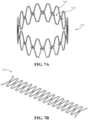
- Figure 7A illustrates still another aspect of the stent spring 120 in the rolled configuration
- Figure 7B illustrates the stent spring 120 of Figure 7A in the unrolled configuration.
- the openings 142 can substantially define an elongated hexagonal shape.
- Figure 8A illustrates the stent spring 120 in the rolled configuration, according to a further aspect of the present disclosure
- Figure 8B illustrates the stent spring 120 of Figure 8A in the unrolled configuration.
- the openings 142 can substantially define a chevron pattern.
- Figure 9A illustrates the stent spring 120 in the rolled configuration
- Figure 9B illustrates the stent spring 120 of Figure 9A in the unrolled configuration
- the openings 142 can substantially define an elongated hexagonal shape
- the stent spring 120 can comprise a spring steel material.
- Example aspects can be coated with a rubber or liquid metal material, zinc-nickel material, phosphate, electrophoretic paint (e-coating), polyester, or fusion-bonded epoxy (FBE), as described above.
- the stent spring 120 can comprise a stainless steel material, or any other suitable spring material.
- example aspects of the stent spring 120 can comprise one or more tabs 960, each defining a tab opening 962 therethrough.
- the tabs 960 can be bent inward towards the void 130 and the compression mechanism can engage the tabs 960 to compress the stent spring 120 to the compressed stent spring configuration.
- a cable (not shown), or other fastening device, can pass through the tab opening 962 of each of the tabs 960 and can be tightened to contract the stent 100 (shown in Figure 1A ) to the compressed configuration.
- Figure 10 illustrates still another aspect of the stent spring 120 the rolled configuration.
- the openings 142 can substantially define an elongated hexagonal shape.
- the stent spring 120 can comprise a carbon fiber material.
- the stent spring 120 comprises the tabs 960 extending radially inward towards the void 130.
- the tabs 960 can be formed extending inward rather than having to be bent inwards, as may be required by the aspect of Figure 9A .
- Each of the tabs 960 can define one of the tab openings 962 therethrough.
- a cable (not shown) can pass through the tab opening 962 of each of the tabs 960 and can be tightened to contract the stent 100 (shown in Figure 1A ) to the compressed configuration through tension in the cable.
- the cable can be cut to release the tension force on the stent 100 and to allow the stent spring 120 to return to the expanded stent spring configuration, thus biasing the stent 100 to the expanded configuration.
- the stent 100 can be compressed by another compression or contraction mechanism, such as a compression sleeve or tube, a dissolvable wire, or any other suitable mechanisms known in the art.
- the wire can be dissolved by electricity, chemicals, water, or any other suitable dissolving mechanism.
- the compression mechanism can be a hose clamp.
- the hose clamp or other compression mechanism can comprise a worm drive.
- Figure 11 illustrates another example aspect of the stent spring 120 in the rolled configuration.
- the present stent spring 120 can comprise an inner stent spring 1122 aligned and connected with an outer stent spring 1124 to provide increased stiffness of the stent spring 120, while maintaining flexibility of the stent spring 120.
- Each of the inner stent spring 1122 and outer stent spring 1124 of the present aspect can be substantially similar in shape to the stent spring 120 illustrated in Figure 10 ; however, in other aspects, the inner and outer stent springs 1122,1124 can be differently shaped.
- the inner and outer stent springs 1122,1124 can be formed from carbon fiber, and in another example aspect, the inner and outer stent springs 1122,1124 can be formed from nylon. In other aspects, the inner and outer stent springs 1122,1124 can be formed from any suitable material, including but not limited to stainless steel, spring steel, aluminum, nitinol, cobalt chromium, POM (polyoxymethylene), and PVC (polyvinyl chloride). According to example aspects, the inner and outer stent springs can be joined together at a plurality of upper bends 1102 and lower bends 1104 thereof, as shown.
- Figures 12 and 13 illustrates an example aspect of the stent spring 120 in the rolled configuration, wherein the tabs 960 are formed as hollow cylindrical structures 1262 each defining the tab opening 962 extending therethrough.
- a coil spring 1220 can extend through the tab openings 962, as shown.
- the coil spring 1220 can define a coil spring force.
- the coil spring 1220 can be compressed in the compressed stent spring configuration and can be expanded in the expanded stent spring configuration.
- a compression force e.g. a pushing force, tension or pulling force, or any other suitable force
- the compression force can overcome the spring force of the stent spring 120 and the coil spring force of the coil spring 1220, and the stent spring 120, coil spring 1220, and seal 170 (shown in Figure 1A ) can be compressed or folded radially inward towards the void 130.
- the stent 100 can define a smaller stent diameter D 1 (shown in Figure 1A ) and a smaller overall stent volume than in the expanded configuration.
- both of the stent spring 120 and the coil spring 1220 can assist in biasing the stent 100 fully back to the expanded configuration.
- example aspects of the stent spring 120 can be formed from a Windform ® material, such as, for example, a Windform ® SP material.
- the Windform SP material is a carbon fiber reinforced composite polyamide material, which can be durable, insulating, and water resistant.
- Figure 14 illustrates the stent spring 120 of Figures 12 and 13 in the unrolled configuration.
- Figures 15 and 16 illustrates an example aspect of the stent spring 120 in the rolled configuration, according to another aspect of the present disclosure.
- the stent spring 120 can be similar to the stent spring 120 illustrated Figure 10 .
- the stent spring 120 of the present aspect can further comprise a wire or wires 1510 connected to one or more of the strands 140 of the stent spring 120.
- the wires 1510 can be a plurality of Nitinol super-elastic wires 1512, which can be configured to provide added flexibility to the stent spring 120.
- each of the Nitinol super-elastic wires 1512 can define a first end 1514, a second end 1516, and a middle section 1517 extending therebetween.
- the first end 1514 can be received within a first groove (not shown) formed within a corresponding first strand 140a, and the second end 1516 can be received within a second groove (not shown) of an adjacent second strand 140b.
- the compression mechanism can be a connecting band 1610.
- the connecting band 1610 can engage each of the tabs 960 of the stent spring 120 to retain the stent spring 120 in the compressed stent spring configuration while the wires 1510 are assembled with the stent spring 120.
- the middle section 1517 of each wire 1510 can be substantially exposed.
- the wires 1510 can be more fully received within the strands 140 of the stent spring 120, such that a lesser portion of the middle section 1517 is exposed, as depicted in Figure 17 , and in still other aspects, the wires 1510 can be completely received within the strands 140.
- Figures 18 and 19 illustrates another aspect, wherein each of the wires 1510 can be positioned on an inner periphery 1810 of the stent spring 120 proximate to an upper bend 1812 or lower bend 1814 thereof.
- the wires 1510 can be connected to the stent spring 120 by an adhesive, or other fastener, and the first and second ends 1514,1516 of the wires 1510 do not extend into the strands 140.
- the first and second ends 1514,1516 of each of the wires 1510 can engage the first and second grooves (not shown) formed in a corresponding strand 140 to connect the wire 1510 to the stent spring 120.
- Example aspects of the stent spring 120 can comprise a coating, such as, for example, a rubber coating.
- the stent spring 120 can be coated in a Plasti Dip ® coating.
- a Plasti Dip ® coating is a synthetic rubber coating that can be applied by spraying, brushing, dipping, or the like, and which can be configured to air dry.
- the Plasti Dip ® material can be non-slip, flexible, durable, and insulating material in some aspects.
- the stent spring 120 can be coated in a Flex Seal ® coating.
- the Flex Seal ® coating is a synthetic rubber coating similar to the Plasti Dip ® coating.
- the Flex Seal ® coating can be applied by pouring, rolling, dippy, spraying, or the like, and can be durable, flexible, insulating, and water resistant.
- the coating can be any other suitable coating known in the art.
- Example aspects of the coating can be flexible and can improve the flexibility of the stent spring 120.
- the coating can also be a non-slip coating that can improve the grip of the stent spring 120 on the seal 170 (shown in Figure 1A ), the pipe (not shown), or any other component engaged by the stent spring 120.
- Figure 22 illustrates the stent spring 120 of Figure 20 without the Plasti Dip ® coating applied.
- Figure 23 illustrates another example aspect of the stent spring 120 that can be substantially similar to the stent spring 120 of Figure 9A .
- the tabs 960 can define larger tab openings 962 than the tab openings 962 shown in Figure 9A .
- the larger tab openings 962 can accommodate for a larger or different compression mechanism for compressing the stent 100 (shown in Figure 1A ).
- Figure 24 illustrates still another example aspect of the stent spring 120, wherein the strands 140 of the stent spring 120 can be a plurality of connected, substantially circular, resilient and flexible strands 2440, as shown.
- the flexibility of the strands 140 can allow the stent spring 120 to be compressed to the compressed stent spring configuration, and the resiliency of the strands 140 can bias the stent spring 120 from the compressed stent spring configuration to the expanded stent spring configuration.
- the stent spring 120 can be compressed by the compression mechanism, as described above.
- the compression mechanism can be an internal compression disc 2510 as illustrated in Figure 25 .
- the compression disc 2510 can engage each of the tabs 960 of the stent spring 120 to pull the stent spring 120 radially inward and to retain the stent spring 120 in the compressed stent spring configuration.
- the compression disc 2510 can comprise an upper disc 2512 and a lower disc 2712 (shown in Figure 27 ) connected to the upper disc 2512.
- Disc openings 2514 can be formed in each of the upper and lower discs 2512,2712 to allow for fluid flow therethrough.
- one or more disc slots 2516 can be formed at an outer side edge 2518 of the compression disc 2510.
- the compression disc 2510 can further comprise a plurality of connectors 2620 generally received between the upper disc 2512 and lower disc 2712 and proximate to the outer side edge 2518 of the compression disc 2510.
- a head 2622 of each of the connectors 2620 can be configured to extend into a corresponding one of the disc slots 2516.
- an inner end 2662 of each of the tabs 960 can be pushed past the head 2622 of the corresponding connector 2620 and into the corresponding disc slot 2516, such that the head 2622 of each connector 2620 extends through the tab opening 962 (shown in Figure 9A ) of the corresponding tab 960.
- the compression disc 2510 can be slid axially relative to the central axis 132 (shown in Figure 1A ).
- the tabs 960 of the stent spring 120 can be pushed past the heads 2622 of the corresponding connectors 2620, such that each of the connectors 2620 can be disengaged from the corresponding tab opening 962, and the compression disc 2510 can be disengaged from the stent spring 120.
- the spring force of the stent spring 120 can bias the stent 100 (shown in Figure 1A ) to the expanded configuration.
- Figures 28 and 29 illustrate another aspect of the stent spring 120 comprising the wires 1510 (e.g., the Nitinol super-elastic wires 1512).
- the stent spring 120 of the present aspect can be similar to the stent spring 120 of Figure 17 , wherein the first end 1514 of each wire 1510 can be received through the first groove (not shown) formed within one of the strands 140, and the second end 1516 of each wire 1510 can be received within the second groove (not shown) formed in the same strand 140.
- Each wire 1510 can be oriented proximate to one of the upper bends 1812 or lower bends 1814 of the stent spring 120, as shown.
- first and second ends 1514,1516 of each of the wires 1510 can pass through the corresponding first and second grooves, respectively, and can abut the inner periphery 1810 of the stent spring 120 proximate to the corresponding upper or lower bend 1812,1814, as shown.
- the middle section 1517 can be exposed.
- Figures 30 and 31 illustrate the stent spring 120 of Figures 18 and 19 dipped in the rubber coating, such as, for example, the Plasti Dip ® coating or the Flex Seal ® coating, as described above with reference to Figures 20 , 21, and 22 .
- the rubber coating such as, for example, the Plasti Dip ® coating or the Flex Seal ® coating, as described above with reference to Figures 20 , 21, and 22 .
- a stent spring for repairing a pipe can comprise a substantially tubular mesh structure defining a void, the void can define a central axis, the mesh structure can comprise one or more strands, and the one or more strands can define a plurality of openings.
- the stent spring can be configurable in an expanded stent spring configuration and a compressed stent spring configuration.
- the stent spring can further comprise a tab extending radially inward from the mesh structure into the void, and the tab can define a tab opening.
- the stent spring can further comprise a compression mechanism configured to engage the tab to bias the stent spring to the compressed stent spring configuration.
- the compression mechanism can comprise a cable configured to extend through the tab opening of the tab.
- the compression mechanism can comprise a compression disc, wherein the compression disc can define a disc slot formed in an outer side edge of the compression disc, and a connector, wherein the connector can comprise a head and the head can extend into the disc slot.
- the tab can extend into the disc slot, and the head can extend through the tab opening.
- the stent spring can further comprise one or more elastic wires connected to the one or more strands, wherein the one or more elastic wires can be configured to increase a flexibility of the stent spring.
- the stent spring can further comprise a coil spring extending through the tab opening, wherein the coil spring can be configured to assist in biasing the stent spring to the expanded stent spring configuration.
- the stent spring can further comprise a flexible coating on the one or more strands, wherein the flexible coating can comprise a synthetic rubber material.
- the stent spring can comprise an inner stent spring connected to an outer stent spring, the inner stent spring can comprise the mesh structure and the tab, and the outer stent spring can be configured to increase a stiffness of the inner stent spring.
- a stent spring for repairing a pipe can comprise a substantially tubular mesh structure comprising one or more strands, and the one or more strands can comprise a spring material.
- the stent spring can be expandable and compressible between an expanded stent spring configuration and a compressed stent spring configuration.
- the stent spring can further comprising an elastic wire connected to the one or more strands, wherein the elastic wire can be configured to increase a flexibility of the stent spring.
- the elastic wire can define a first end and a second end, the first end of the elastic wire can engage a first one of the strands, and the second end of the elastic wire can engage a second one of the strands.
- the first one of the strands can define a first groove
- the second one of the strands can define a second groove
- the first end can be received within the first groove
- the second end can be received within the second groove.
- the elastic wire can define a middle section between the first end and second end, and at least a portion of the middle section can be exposed.
- the elastic wire can be positioned on an inner periphery of the stent spring.
- the one or more strands can define at least one of an upper bend and a lower bend, and the elastic wire can be positioned proximate to the at least one of an upper bend and a lower bend.
- a first end of the elastic wire can extend through a first groove of the mesh structure and abut an inner periphery of the stent spring
- a second end of the elastic wire can extend through a second groove of the mesh structure and abut an inner periphery of the stent spring
- a middle section of the elastic wire can be exposed.
- the one or more strands can define a plurality of openings.
- the stent spring can further comprise a tab extending radially inward from the mesh structure and a compression mechanism engaging the tab to retain the stent spring in the compressed stent spring configuration.
- a method for retaining a stent in a compressed configuration can comprise providing a stent, wherein the stent can comprise a stent spring, a seal, and a tab extending radially inward from the stent spring.
- the method can further comprise biasing the stent to a compressed configuration and engaging the tab with a compression mechanism to retain the stent in the compressed configuration.
- engaging the tab with a compression mechanism can comprise inserting the tab into a disc slot of the compression mechanism and engaging a tab opening of the tab with a connector of the compression mechanism.
- a stent in another exemplary aspect, can comprise a stent spring and a seal wrapped around a circumference of the stent spring, the stent spring can define a substantially tubular mesh structure, the stent can be configurable in an expanded configuration and a compressed configuration, and the stent spring can bias the stent to the expanded configuration.
- conditional language such as, among others, "can,” “could,” “might,” or “may,” unless specifically stated otherwise, or otherwise understood within the context as used, is generally intended to convey that certain embodiments include, while other embodiments do not include, certain features, elements and/or steps. Thus, such conditional language is not generally intended to imply that features, elements and/or steps are in any way required for one or more particular embodiments or that one or more particular embodiments necessarily include logic for deciding, with or without user input or prompting, whether these features, elements and/or steps are included or are to be performed in any particular embodiment.
Applications Claiming Priority (4)
| Application Number | Priority Date | Filing Date | Title |
|---|---|---|---|
| US201962807264P | 2019-02-19 | 2019-02-19 | |
| US201962834168P | 2019-04-15 | 2019-04-15 | |
| PCT/US2020/018593 WO2020172136A1 (fr) | 2019-02-19 | 2020-02-18 | Ressorts d'endoprothèse et endoprothèses pour réparer des tuyaux |
| EP20758706.4A EP3928022A4 (fr) | 2019-02-19 | 2020-02-18 | Ressorts d'endoprothèse et endoprothèses pour réparer des tuyaux |
Related Parent Applications (2)
| Application Number | Title | Priority Date | Filing Date |
|---|---|---|---|
| EP20758706.4A Division EP3928022A4 (fr) | 2019-02-19 | 2020-02-18 | Ressorts d'endoprothèse et endoprothèses pour réparer des tuyaux |
| EP20758706.4A Division-Into EP3928022A4 (fr) | 2019-02-19 | 2020-02-18 | Ressorts d'endoprothèse et endoprothèses pour réparer des tuyaux |
Publications (1)
| Publication Number | Publication Date |
|---|---|
| EP4148316A1 true EP4148316A1 (fr) | 2023-03-15 |
Family
ID=72041948
Family Applications (2)
| Application Number | Title | Priority Date | Filing Date |
|---|---|---|---|
| EP22204247.5A Pending EP4148316A1 (fr) | 2019-02-19 | 2020-02-18 | Ressorts et stents pour la réparation de tuyaux |
| EP20758706.4A Pending EP3928022A4 (fr) | 2019-02-19 | 2020-02-18 | Ressorts d'endoprothèse et endoprothèses pour réparer des tuyaux |
Family Applications After (1)
| Application Number | Title | Priority Date | Filing Date |
|---|---|---|---|
| EP20758706.4A Pending EP3928022A4 (fr) | 2019-02-19 | 2020-02-18 | Ressorts d'endoprothèse et endoprothèses pour réparer des tuyaux |
Country Status (3)
| Country | Link |
|---|---|
| US (3) | US11353154B2 (fr) |
| EP (2) | EP4148316A1 (fr) |
| WO (1) | WO2020172136A1 (fr) |
Families Citing this family (8)
| Publication number | Priority date | Publication date | Assignee | Title |
|---|---|---|---|---|
| US10641427B2 (en) | 2018-04-03 | 2020-05-05 | Mueller International, Llc | Stents and methods for repairing pipes |
| WO2020172136A1 (fr) | 2019-02-19 | 2020-08-27 | Mueller International, Llc | Ressorts d'endoprothèse et endoprothèses pour réparer des tuyaux |
| US11079058B2 (en) | 2019-03-15 | 2021-08-03 | Mueller International , LLC | Stent with coiled spring |
| US11187366B2 (en) | 2019-03-15 | 2021-11-30 | Mueller International, Llc | Stent for repairing a pipe |
| US11326731B2 (en) | 2019-04-24 | 2022-05-10 | Mueller International, Llc | Pipe repair assembly |
| US11802646B2 (en) | 2019-08-09 | 2023-10-31 | Mueller International, Llc | Pipe repair device |
| US11391405B2 (en) | 2019-08-09 | 2022-07-19 | Mueller International, Llc | Deployment probe for pipe repair device |
| US20230338175A1 (en) * | 2022-04-26 | 2023-10-26 | Accumedical Beijing Ltd. | Repositionable intracranial stent with retrieval mechanism |
Citations (3)
| Publication number | Priority date | Publication date | Assignee | Title |
|---|---|---|---|---|
| US6270524B1 (en) * | 1996-11-12 | 2001-08-07 | Medtronic, Inc. | Flexible, radially expansible luminal prostheses |
| US6375677B1 (en) * | 1996-03-05 | 2002-04-23 | Ewysio Medical Devices Inc. | Expandable stent and method for delivery of same |
| US20130131783A1 (en) * | 2011-02-03 | 2013-05-23 | Endospan Ltd. | Implantable medical devices constructed of shape memory material |
Family Cites Families (61)
| Publication number | Priority date | Publication date | Assignee | Title |
|---|---|---|---|---|
| US3656771A (en) | 1970-12-11 | 1972-04-18 | Irrigation Accessories Co | Flexible seal assembly for spigot and bell conduit joint |
| US3895652A (en) | 1974-01-11 | 1975-07-22 | Roger G Zach | Diametrically expansible coil spring conduit plug |
| US4426095A (en) | 1981-09-28 | 1984-01-17 | Concrete Pipe & Products Corp. | Flexible seal |
| US4589447A (en) | 1983-08-03 | 1986-05-20 | Owens-Corning Fiberglas Corporation | Method of depositing a membrane within a conduit |
| EP0159300A1 (fr) | 1984-03-30 | 1985-10-23 | Stig Westman | Douille de réparation pour tuyaux |
| DE3610626A1 (de) | 1986-03-29 | 1987-10-08 | Norske Stats Oljeselskap | Vorrichtung zum erzeugen von radial auf eine zylindrische flaeche wirkenden kraeften, insbesondere anstell- oder haltekraeften |
| US5119862A (en) | 1988-10-31 | 1992-06-09 | Link-Pipe Technlogies, Inc. | Conduit repair apparatus |
| US4927189A (en) | 1989-04-10 | 1990-05-22 | Burkit John W | Internal expansion coupling device |
| AU630482B2 (en) | 1989-08-14 | 1992-10-29 | Kabushiki Kaisha Iseki Kaihatsu Koki | Liner for pipeline repair and method for repairing pipelines |
| US5351720A (en) | 1992-03-10 | 1994-10-04 | Link-Pipe, Inc. | Apparatus for repairing conduits |
| EP0621015B1 (fr) | 1993-04-23 | 1998-03-18 | Schneider (Europe) Ag | Endoprothèse avec une couche de couverture en matériau élastique et procédé pour appliquer la couche sur l'endoprothèse |
| US5624124A (en) | 1996-07-15 | 1997-04-29 | Fmc Corporation | Bore seal assembly with wear ring having curvilinear spring support surface |
| DK174814B1 (da) | 1998-02-25 | 2003-12-01 | Cook William Europ | Stentaggregat |
| AU754156B2 (en) | 1998-06-02 | 2002-11-07 | Cook Incorporated | Multiple-sided intraluminal medical device |
| US6820653B1 (en) | 1999-04-12 | 2004-11-23 | Carnegie Mellon University | Pipe inspection and repair system |
| AU2001238038B2 (en) | 2000-02-03 | 2005-08-25 | Cook Biotech, Inc. | Implantable vascular device |
| US7267141B1 (en) * | 2000-06-05 | 2007-09-11 | Milliken & Company | Method of on-site production of novel textile reinforced thermoplastic or thermoset pipes |
| EP1345754A4 (fr) * | 2000-06-09 | 2006-04-19 | Fiberliner Networks | Procede et dispositif pour equiper un conduit d'une garniture interne |
| NO335594B1 (no) | 2001-01-16 | 2015-01-12 | Halliburton Energy Serv Inc | Ekspanderbare anordninger og fremgangsmåte for disse |
| US6648071B2 (en) * | 2001-01-24 | 2003-11-18 | Schlumberger Technology Corporation | Apparatus comprising expandable bistable tubulars and methods for their use in wellbores |
| US6712556B2 (en) | 2001-05-18 | 2004-03-30 | G. Gregory Penza | Method and apparatus for routing cable in existing pipelines |
| CA2450160C (fr) | 2001-06-11 | 2011-03-22 | Boston Scientific Limited | Prothese composite eptfe/textile |
| US8488290B2 (en) | 2001-06-15 | 2013-07-16 | George M. Kauffman | Protective device |
| WO2003018100A1 (fr) | 2001-08-22 | 2003-03-06 | Hasan Semih Oktay | Stent d'expansion commande actionne par des systemes microelectromecaniques (mems) flexibles |
| CA2486390C (fr) | 2002-05-29 | 2011-01-04 | William A. Cook Australia Pty. Ltd. | Systeme de fils de declenchement pour un dispositif de deploiement de prothese |
| US7611528B2 (en) | 2003-01-24 | 2009-11-03 | Medtronic Vascular, Inc. | Stent-graft delivery system |
| US7776078B2 (en) | 2003-05-22 | 2010-08-17 | Boston Scientfic Scimed, Inc. | Catheter balloon with improved retention |
| DE10357061B4 (de) * | 2003-12-04 | 2005-09-08 | Tracto-Technik Gmbh | Schneidsystem, Vorrichtung und Verfahren zum Zerteilen von Rohren |
| US20050212220A1 (en) | 2004-03-26 | 2005-09-29 | Stamped Fittings, Inc. | Gasket for duct, pipe and tube joints |
| JP2005278993A (ja) | 2004-03-30 | 2005-10-13 | Terumo Corp | 生体内留置用ステントおよびその製造方法 |
| KR100732864B1 (ko) | 2005-08-10 | 2007-06-27 | 이철민 | 비 굴착식 관로 보수용 메쉬철망 설치공법 |
| JP5109195B2 (ja) * | 2006-11-30 | 2012-12-26 | クック・メディカル・テクノロジーズ・リミテッド・ライアビリティ・カンパニー | 体内埋入物解放機構 |
| US7896915B2 (en) | 2007-04-13 | 2011-03-01 | Jenavalve Technology, Inc. | Medical device for treating a heart valve insufficiency |
| US20090171448A1 (en) * | 2007-04-27 | 2009-07-02 | Uri Eli | Implantable device with miniature rotating portion for energy harvesting |
| US7806919B2 (en) * | 2008-04-01 | 2010-10-05 | Medtronic Vascular, Inc. | Double-walled stent system |
| US8652202B2 (en) | 2008-08-22 | 2014-02-18 | Edwards Lifesciences Corporation | Prosthetic heart valve and delivery apparatus |
| US9052051B2 (en) | 2009-04-20 | 2015-06-09 | Link-Pipe, Inc. | Apparatus and method for internal repair of conduits |
| GB0911579D0 (en) * | 2009-07-03 | 2009-08-12 | Brinker Technology Ltd | Apparatus and methods for maintenance and repair of vessels |
| US9326870B2 (en) | 2010-04-23 | 2016-05-03 | Medtronic Vascular, Inc. | Biodegradable stent having non-biodegradable end portions and mechanisms for increased stent hoop strength |
| US8783297B2 (en) * | 2011-04-27 | 2014-07-22 | Massachusetts Institute Of Technology | Robotic system for pipeline rehabilitation |
| US20130018450A1 (en) | 2011-07-13 | 2013-01-17 | Hunt James B | Prosthesis delivery system with retention sleeve |
| EP2604232B1 (fr) * | 2011-12-14 | 2021-02-24 | Cook Medical Technologies LLC | Fil de déclenchement circonférentiel pour déployer une prothèse endoluminale |
| US20130248042A1 (en) | 2012-03-23 | 2013-09-26 | Altran Solutions Corp. | Methods and apparatuses for repairing a conduit |
| WO2014204807A1 (fr) * | 2013-06-19 | 2014-12-24 | Aga Medical Corporation | Valvule repliable pourvue d'une protection contre les fuites paravalvulaires |
| US20160238178A1 (en) | 2013-10-29 | 2016-08-18 | Jeffrey M. Urbanski | Apparatus For Repairing A Pipe |
| US10111741B2 (en) | 2014-10-29 | 2018-10-30 | W. L. Gore & Associates, Inc. | Intralumenal stent graft fixation |
| US9433520B2 (en) | 2015-01-29 | 2016-09-06 | Intact Vascular, Inc. | Delivery device and method of delivery |
| EP3294221B1 (fr) | 2015-05-14 | 2024-03-06 | Cephea Valve Technologies, Inc. | Valvules mitrales de remplacement |
| US10265169B2 (en) | 2015-11-23 | 2019-04-23 | Edwards Lifesciences Corporation | Apparatus for controlled heart valve delivery |
| WO2017189364A1 (fr) | 2016-04-25 | 2017-11-02 | Solinas Medical, Inc. | Greffons tubulaires auto-obturants, patches et leurs procédés de fabrication et d'utilisation |
| DE102016006561B4 (de) | 2016-05-25 | 2022-07-28 | Uhrig Kanaltechnik Gmbh | Dichtungsmanschette für Rohrversätze |
| CN110621260B (zh) | 2017-01-23 | 2022-11-25 | 科菲瓣膜技术有限公司 | 置换的二尖瓣 |
| US10627038B2 (en) | 2017-09-26 | 2020-04-21 | Mueller International, Llc | Devices and methods for repairing pipes |
| DE202018100823U1 (de) | 2018-02-15 | 2018-05-16 | Hans Bohnet | Dichtungsmanschette zum Einsetzen in ein Rohrleitungssystem |
| US10641427B2 (en) | 2018-04-03 | 2020-05-05 | Mueller International, Llc | Stents and methods for repairing pipes |
| WO2020172136A1 (fr) | 2019-02-19 | 2020-08-27 | Mueller International, Llc | Ressorts d'endoprothèse et endoprothèses pour réparer des tuyaux |
| US11079058B2 (en) | 2019-03-15 | 2021-08-03 | Mueller International , LLC | Stent with coiled spring |
| US11187366B2 (en) | 2019-03-15 | 2021-11-30 | Mueller International, Llc | Stent for repairing a pipe |
| US11326731B2 (en) | 2019-04-24 | 2022-05-10 | Mueller International, Llc | Pipe repair assembly |
| US11802646B2 (en) | 2019-08-09 | 2023-10-31 | Mueller International, Llc | Pipe repair device |
| US11391405B2 (en) | 2019-08-09 | 2022-07-19 | Mueller International, Llc | Deployment probe for pipe repair device |
-
2020
- 2020-02-18 WO PCT/US2020/018593 patent/WO2020172136A1/fr unknown
- 2020-02-18 EP EP22204247.5A patent/EP4148316A1/fr active Pending
- 2020-02-18 US US16/792,984 patent/US11353154B2/en active Active
- 2020-02-18 EP EP20758706.4A patent/EP3928022A4/fr active Pending
-
2022
- 2022-04-22 US US17/727,574 patent/US11781697B2/en active Active
-
2023
- 2023-08-25 US US18/237,948 patent/US20230408018A1/en active Pending
Patent Citations (3)
| Publication number | Priority date | Publication date | Assignee | Title |
|---|---|---|---|---|
| US6375677B1 (en) * | 1996-03-05 | 2002-04-23 | Ewysio Medical Devices Inc. | Expandable stent and method for delivery of same |
| US6270524B1 (en) * | 1996-11-12 | 2001-08-07 | Medtronic, Inc. | Flexible, radially expansible luminal prostheses |
| US20130131783A1 (en) * | 2011-02-03 | 2013-05-23 | Endospan Ltd. | Implantable medical devices constructed of shape memory material |
Also Published As
| Publication number | Publication date |
|---|---|
| US11353154B2 (en) | 2022-06-07 |
| US11781697B2 (en) | 2023-10-10 |
| US20200263823A1 (en) | 2020-08-20 |
| US20230408018A1 (en) | 2023-12-21 |
| WO2020172136A1 (fr) | 2020-08-27 |
| US20220243854A1 (en) | 2022-08-04 |
| EP3928022A4 (fr) | 2022-12-14 |
| EP3928022A1 (fr) | 2021-12-29 |
Similar Documents
| Publication | Publication Date | Title |
|---|---|---|
| US11781697B2 (en) | Stent springs and stents for repairing pipes | |
| US11221099B2 (en) | Stents and methods for repairing pipes | |
| US11187366B2 (en) | Stent for repairing a pipe | |
| US11802646B2 (en) | Pipe repair device | |
| US20200292119A1 (en) | Stent with coiled spring | |
| US20110083766A1 (en) | Rehabilitation Liner System | |
| US11326731B2 (en) | Pipe repair assembly | |
| CA2594236C (fr) | Procede et dispositif permettant de reparer ou de renforcer un tuyau souterrain | |
| CN102245954A (zh) | 柔性多壁管路组件 | |
| JP5236936B2 (ja) | 可撓性管継手 | |
| KR101397531B1 (ko) | 공기 조화기 설치용 배관 장치 | |
| KR100881351B1 (ko) | 이탈 방지구조로 이루어진 확관단부를 갖는 관 | |
| JP4871327B2 (ja) | 更生管用のセグメント | |
| JP4964706B2 (ja) | 管継手 | |
| JP6826345B2 (ja) | 管路更生方法 | |
| JP2018179269A (ja) | 接続管および接続管の敷設方法 | |
| JP6625881B2 (ja) | 帯状ゴム部材、補修部材、既設管路の内面補修構造 | |
| JP3180434U (ja) | 高水密性管継手 | |
| JP4493483B2 (ja) | マンホール用可とう継手の拡張バンド及び接続構造 | |
| JP6144958B2 (ja) | 可とう継手、可とう継手構造及び可とう継手の組立方法 | |
| JP2016188488A (ja) | 給水管 | |
| JP2004076809A (ja) | 可撓管 | |
| JP2016164456A (ja) | 管路更生用管及びその製造方法、管路構造 |
Legal Events
| Date | Code | Title | Description |
|---|---|---|---|
| PUAI | Public reference made under article 153(3) epc to a published international application that has entered the european phase |
Free format text: ORIGINAL CODE: 0009012 |
|
| STAA | Information on the status of an ep patent application or granted ep patent |
Free format text: STATUS: THE APPLICATION HAS BEEN PUBLISHED |
|
| AC | Divisional application: reference to earlier application |
Ref document number: 3928022 Country of ref document: EP Kind code of ref document: P |
|
| AK | Designated contracting states |
Kind code of ref document: A1 Designated state(s): AL AT BE BG CH CY CZ DE DK EE ES FI FR GB GR HR HU IE IS IT LI LT LU LV MC MK MT NL NO PL PT RO RS SE SI SK SM TR |
|
| STAA | Information on the status of an ep patent application or granted ep patent |
Free format text: STATUS: REQUEST FOR EXAMINATION WAS MADE |
|
| 17P | Request for examination filed |
Effective date: 20230425 |
|
| RBV | Designated contracting states (corrected) |
Designated state(s): AL AT BE BG CH CY CZ DE DK EE ES FI FR GB GR HR HU IE IS IT LI LT LU LV MC MK MT NL NO PL PT RO RS SE SI SK SM TR |
|
| P01 | Opt-out of the competence of the unified patent court (upc) registered |
Effective date: 20230804 |