EP4146890B1 - Möbelbeschlag - Google Patents
Möbelbeschlag Download PDFInfo
- Publication number
- EP4146890B1 EP4146890B1 EP21723104.2A EP21723104A EP4146890B1 EP 4146890 B1 EP4146890 B1 EP 4146890B1 EP 21723104 A EP21723104 A EP 21723104A EP 4146890 B1 EP4146890 B1 EP 4146890B1
- Authority
- EP
- European Patent Office
- Prior art keywords
- furniture
- component
- wall
- bearing axis
- fitting
- Prior art date
- Legal status (The legal status is an assumption and is not a legal conclusion. Google has not performed a legal analysis and makes no representation as to the accuracy of the status listed.)
- Active
Links
Images



Classifications
-
- E—FIXED CONSTRUCTIONS
- E05—LOCKS; KEYS; WINDOW OR DOOR FITTINGS; SAFES
- E05D—HINGES OR SUSPENSION DEVICES FOR DOORS, WINDOWS OR WINGS
- E05D15/00—Suspension arrangements for wings
- E05D15/40—Suspension arrangements for wings supported on arms movable in vertical planes
-
- E—FIXED CONSTRUCTIONS
- E05—LOCKS; KEYS; WINDOW OR DOOR FITTINGS; SAFES
- E05D—HINGES OR SUSPENSION DEVICES FOR DOORS, WINDOWS OR WINGS
- E05D11/00—Additional features or accessories of hinges
- E05D11/02—Lubricating arrangements
-
- E—FIXED CONSTRUCTIONS
- E05—LOCKS; KEYS; WINDOW OR DOOR FITTINGS; SAFES
- E05D—HINGES OR SUSPENSION DEVICES FOR DOORS, WINDOWS OR WINGS
- E05D3/00—Hinges with pins
- E05D3/06—Hinges with pins with two or more pins
-
- E—FIXED CONSTRUCTIONS
- E05—LOCKS; KEYS; WINDOW OR DOOR FITTINGS; SAFES
- E05F—DEVICES FOR MOVING WINGS INTO OPEN OR CLOSED POSITION; CHECKS FOR WINGS; WING FITTINGS NOT OTHERWISE PROVIDED FOR, CONCERNED WITH THE FUNCTIONING OF THE WING
- E05F1/00—Closers or openers for wings, not otherwise provided for in this subclass
- E05F1/08—Closers or openers for wings, not otherwise provided for in this subclass spring-actuated, e.g. for horizontally sliding wings
- E05F1/10—Closers or openers for wings, not otherwise provided for in this subclass spring-actuated, e.g. for horizontally sliding wings for swinging wings, e.g. counterbalance
-
- E—FIXED CONSTRUCTIONS
- E05—LOCKS; KEYS; WINDOW OR DOOR FITTINGS; SAFES
- E05F—DEVICES FOR MOVING WINGS INTO OPEN OR CLOSED POSITION; CHECKS FOR WINGS; WING FITTINGS NOT OTHERWISE PROVIDED FOR, CONCERNED WITH THE FUNCTIONING OF THE WING
- E05F1/00—Closers or openers for wings, not otherwise provided for in this subclass
- E05F1/08—Closers or openers for wings, not otherwise provided for in this subclass spring-actuated, e.g. for horizontally sliding wings
- E05F1/10—Closers or openers for wings, not otherwise provided for in this subclass spring-actuated, e.g. for horizontally sliding wings for swinging wings, e.g. counterbalance
- E05F1/12—Mechanisms in the shape of hinges or pivots, operated by springs
- E05F1/1246—Mechanisms in the shape of hinges or pivots, operated by springs with a coil spring perpendicular to the pivot axis
- E05F1/1253—Mechanisms in the shape of hinges or pivots, operated by springs with a coil spring perpendicular to the pivot axis with a compression spring
- E05F1/1261—Mechanisms in the shape of hinges or pivots, operated by springs with a coil spring perpendicular to the pivot axis with a compression spring for counterbalancing
-
- E—FIXED CONSTRUCTIONS
- E05—LOCKS; KEYS; WINDOW OR DOOR FITTINGS; SAFES
- E05Y—INDEXING SCHEME ASSOCIATED WITH SUBCLASSES E05D AND E05F, RELATING TO CONSTRUCTION ELEMENTS, ELECTRIC CONTROL, POWER SUPPLY, POWER SIGNAL OR TRANSMISSION, USER INTERFACES, MOUNTING OR COUPLING, DETAILS, ACCESSORIES, AUXILIARY OPERATIONS NOT OTHERWISE PROVIDED FOR, APPLICATION THEREOF
- E05Y2201/00—Constructional elements; Accessories therefor
- E05Y2201/60—Suspension or transmission members; Accessories therefor
- E05Y2201/622—Suspension or transmission members elements
- E05Y2201/624—Arms
-
- E—FIXED CONSTRUCTIONS
- E05—LOCKS; KEYS; WINDOW OR DOOR FITTINGS; SAFES
- E05Y—INDEXING SCHEME ASSOCIATED WITH SUBCLASSES E05D AND E05F, RELATING TO CONSTRUCTION ELEMENTS, ELECTRIC CONTROL, POWER SUPPLY, POWER SIGNAL OR TRANSMISSION, USER INTERFACES, MOUNTING OR COUPLING, DETAILS, ACCESSORIES, AUXILIARY OPERATIONS NOT OTHERWISE PROVIDED FOR, APPLICATION THEREOF
- E05Y2201/00—Constructional elements; Accessories therefor
- E05Y2201/60—Suspension or transmission members; Accessories therefor
- E05Y2201/622—Suspension or transmission members elements
- E05Y2201/706—Shafts
-
- E—FIXED CONSTRUCTIONS
- E05—LOCKS; KEYS; WINDOW OR DOOR FITTINGS; SAFES
- E05Y—INDEXING SCHEME ASSOCIATED WITH SUBCLASSES E05D AND E05F, RELATING TO CONSTRUCTION ELEMENTS, ELECTRIC CONTROL, POWER SUPPLY, POWER SIGNAL OR TRANSMISSION, USER INTERFACES, MOUNTING OR COUPLING, DETAILS, ACCESSORIES, AUXILIARY OPERATIONS NOT OTHERWISE PROVIDED FOR, APPLICATION THEREOF
- E05Y2600/00—Mounting or coupling arrangements for elements provided for in this subclass
- E05Y2600/50—Mounting methods; Positioning
- E05Y2600/506—Plastic deformation
- E05Y2600/508—Riveting
-
- E—FIXED CONSTRUCTIONS
- E05—LOCKS; KEYS; WINDOW OR DOOR FITTINGS; SAFES
- E05Y—INDEXING SCHEME ASSOCIATED WITH SUBCLASSES E05D AND E05F, RELATING TO CONSTRUCTION ELEMENTS, ELECTRIC CONTROL, POWER SUPPLY, POWER SIGNAL OR TRANSMISSION, USER INTERFACES, MOUNTING OR COUPLING, DETAILS, ACCESSORIES, AUXILIARY OPERATIONS NOT OTHERWISE PROVIDED FOR, APPLICATION THEREOF
- E05Y2600/00—Mounting or coupling arrangements for elements provided for in this subclass
- E05Y2600/60—Mounting or coupling members; Accessories therefor
- E05Y2600/622—Dowels; Pins
-
- E—FIXED CONSTRUCTIONS
- E05—LOCKS; KEYS; WINDOW OR DOOR FITTINGS; SAFES
- E05Y—INDEXING SCHEME ASSOCIATED WITH SUBCLASSES E05D AND E05F, RELATING TO CONSTRUCTION ELEMENTS, ELECTRIC CONTROL, POWER SUPPLY, POWER SIGNAL OR TRANSMISSION, USER INTERFACES, MOUNTING OR COUPLING, DETAILS, ACCESSORIES, AUXILIARY OPERATIONS NOT OTHERWISE PROVIDED FOR, APPLICATION THEREOF
- E05Y2600/00—Mounting or coupling arrangements for elements provided for in this subclass
- E05Y2600/60—Mounting or coupling members; Accessories therefor
- E05Y2600/634—Spacers
- E05Y2600/636—Washers
-
- E—FIXED CONSTRUCTIONS
- E05—LOCKS; KEYS; WINDOW OR DOOR FITTINGS; SAFES
- E05Y—INDEXING SCHEME ASSOCIATED WITH SUBCLASSES E05D AND E05F, RELATING TO CONSTRUCTION ELEMENTS, ELECTRIC CONTROL, POWER SUPPLY, POWER SIGNAL OR TRANSMISSION, USER INTERFACES, MOUNTING OR COUPLING, DETAILS, ACCESSORIES, AUXILIARY OPERATIONS NOT OTHERWISE PROVIDED FOR, APPLICATION THEREOF
- E05Y2800/00—Details, accessories and auxiliary operations not otherwise provided for
- E05Y2800/10—Additional functions
- E05Y2800/108—Lubrication
-
- E—FIXED CONSTRUCTIONS
- E05—LOCKS; KEYS; WINDOW OR DOOR FITTINGS; SAFES
- E05Y—INDEXING SCHEME ASSOCIATED WITH SUBCLASSES E05D AND E05F, RELATING TO CONSTRUCTION ELEMENTS, ELECTRIC CONTROL, POWER SUPPLY, POWER SIGNAL OR TRANSMISSION, USER INTERFACES, MOUNTING OR COUPLING, DETAILS, ACCESSORIES, AUXILIARY OPERATIONS NOT OTHERWISE PROVIDED FOR, APPLICATION THEREOF
- E05Y2800/00—Details, accessories and auxiliary operations not otherwise provided for
- E05Y2800/26—Form or shape
-
- E—FIXED CONSTRUCTIONS
- E05—LOCKS; KEYS; WINDOW OR DOOR FITTINGS; SAFES
- E05Y—INDEXING SCHEME ASSOCIATED WITH SUBCLASSES E05D AND E05F, RELATING TO CONSTRUCTION ELEMENTS, ELECTRIC CONTROL, POWER SUPPLY, POWER SIGNAL OR TRANSMISSION, USER INTERFACES, MOUNTING OR COUPLING, DETAILS, ACCESSORIES, AUXILIARY OPERATIONS NOT OTHERWISE PROVIDED FOR, APPLICATION THEREOF
- E05Y2900/00—Application of doors, windows, wings or fittings thereof
- E05Y2900/20—Application of doors, windows, wings or fittings thereof for furniture, e.g. cabinets
Definitions
- the present invention relates to a furniture fitting for the movable mounting of at least one furniture part on a furniture body, wherein the furniture fitting has at least a first component and at least a second component, wherein the two components are connected to one another via at least one pivot bearing with a bearing axis, and wherein the at least one first component has at least a first wall, wherein the at least one pivot bearing has at least one capillary disk with at least a second wall, wherein the second wall is spaced from the first wall of the first component by a preferably annular gap with a gap width, wherein the gap width decreases radially in the direction of the bearing axis at least in sections, so that a lubricant filled into the gap can be conveyed by a capillary force radially in the direction of the bearing axis and/or along the bearing axis.
- the invention relates to a piece of furniture with a furniture body and at least one furniture part that is mounted so as to be movable relative to the furniture body, in particular a furniture flap that can be pivoted about a horizontal axis relative to the furniture body, wherein the piece of furniture has at least one furniture fitting of the type to be described.
- the invention relates to a method for producing a furniture fitting of the type to be described.
- the articulated connection of two components of a furniture fitting is often achieved by a forming process known as necking or collaring.
- a recess for example a cylindrical hole
- a necking tool is then inserted into the recess of the first component in a first direction of movement.
- the necking tool is rotated and a forming die of the necking tool is extended.
- the peripheral edge of the recess is then slowly pulled by the rotating forming die in a second direction of movement opposite to the first direction of movement until the characteristic neck or collar is finally formed.
- This neck or collar forms a pivot bearing with an enlarged support surface on which the second component of the furniture fitting can be pivotally mounted.
- the formation of a neck or collar also has the disadvantage that the overall height of the furniture fitting increases.
- furniture fittings (particularly actuators for furniture flaps) have been integrated completely or partially into a furniture panel of a furniture body. In this way, the furniture fitting is hardly noticeable from an optical point of view. It is therefore a primary goal to make the furniture fitting as compact as possible (i.e. with a small thickness) so that when the furniture fitting is assembled, a covering layer of the furniture panel remains on both sides of the furniture fitting housing.
- the object of the present invention is to propose a furniture fitting of the type mentioned at the beginning, which should be compact and have a long service life.
- the at least one pivot bearing has at least one capillary disk with at least one second wall, wherein the second wall is spaced from the first wall of the first component by a preferably annular gap with a gap width, wherein the gap width decreases radially in the direction of the bearing axis at least in sections, so that a lubricant filled into the gap can be conveyed radially in the direction of the bearing axis and/or along the bearing axis by a capillary force.
- the invention is based on the basic idea of improving the flow of a lubricant into a narrow gap in the swivel bearing of the furniture fitting by means of a capillary disc, whereby the lubricant is drawn into the gap by capillarity and the lubricant can be distributed more effectively in the area of the swivel bearing.
- the swivel bearing can be sufficiently supplied with lubricant. and the service life of the furniture fitting can be increased.
- the manufacture of a neck or collar in the area of the bearing point can be dispensed with. This has the advantage that the furniture fitting can be made compact (ie without the presence of thick lever packages).
- the second wall of the at least one capillary disk runs obliquely in a first gap section and parallel to the first wall of the first component in a second gap section, preferably wherein the two walls in the first gap section enclose an angle between 15° and 45°, particularly preferably an angle of 30°, relative to one another.
- the first, obliquely running gap section thus forms a depot for the lubricant, from which the lubricant can be distributed in a radial direction towards the bearing axis and along the bearing axis.
- the at least one first component can have at least two sections spaced apart from one another in the direction of the bearing axis, wherein the second component is arranged at least in some areas between the two sections of the first component.
- the bearing axis can be designed as a rivet, for example, wherein at least one capillary disk is accommodated between a preferably widened end region of the rivet and the first wall of the first component.
- At least one capillary disk can be arranged at least partially between the two components.
- the furniture fitting has a housing and at least one actuating arm arrangement pivotable relative to the housing with at least two actuating arms, wherein the two actuating arms are connected to one another by the at least one pivot bearing.
- the furniture according to the invention has a furniture body and at least one furniture part that is mounted so as to be movable relative to the furniture body, in particular a furniture flap that can be pivoted about a horizontal axis relative to the furniture body, wherein the furniture comprises at least one furniture fitting of the type in question.
- the bearing axis is designed as a rivet, and wherein at least one end region of the rivet is deformed in a further method step, preferably wherein the at least one capillary disk is received between the first wall and the deformed end region of the rivet.
- the at least one capillary disk is designed as a separate component from the two components.
- the at least one capillary disk is designed as a single piece with one of the two components.
- Fig. 1a shows a perspective view of a piece of furniture 1, which has a furniture body 2, a furniture part 3 that is mounted so that it can move relative to the furniture body 2 and at least one furniture fitting 4, for example in the form of a furniture drive 4a, for moving the movable furniture part 3.
- the piece of furniture 1 has furniture panels 6 in the form of side walls, an upper floor 7 and a lower floor 8.
- the movable furniture part 3 can be designed, for example, as a furniture flap 3a that can be pivoted about a horizontal axis relative to the furniture body 2.
- a housing 9 of the furniture fitting 4 is at least partially, preferably substantially completely, accommodated in the side wall designed as a furniture panel 6.
- the movable furniture part 3 is movably mounted between a closed position covering the furniture body 2 and an open position raised relative to the furniture body 2.
- the furniture fitting 4 in a horizontally running furniture panel, for example in the top panel 7, the bottom panel 8 and/or in a shelf arranged between the top panel 7 and the bottom panel 8.
- the movable furniture part 3 is pivotally mounted relative to the furniture body 2 about an axis that runs vertically in the assembly position.
- the furniture fitting 4 has an actuating arm arrangement 5 for moving the movable furniture part 3 and at least one spring device 10 ( Fig. 1b ) for applying force to the actuating arm arrangement 5.
- Fig.1b shows the furniture 1 in an exploded view, wherein two, preferably identically designed, furniture fittings 4 in the form of furniture drives 4a are provided for moving the movable furniture part 3.
- the furniture fittings 4 each have a housing 9 to be attached to the furniture body 2.
- the housing 9 of the furniture fitting 4 is accommodated in an assembled state at least partially, preferably essentially completely, within a recess 11 of the side walls designed as furniture panels 6.
- the housing 9 can be essentially flush with an end face 6a of the furniture panel 6.
- the recess 11 is designed, for example, as a blind hole, wherein the housing 9 of the furniture fitting 4 can be inserted into the pocket-shaped recess 11 of the furniture panel 6 from the front during assembly (i.e. starting from the narrow front side 6a of the furniture panel 6). In an assembled state, the housing 9 of the furniture fitting 4 is essentially completely accommodated within a predetermined wall thickness of the furniture panel 6.
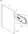
- Fig. 2 shows a perspective view of the furniture fitting 4 to be arranged in the furniture panel 6, wherein the housing 9 of the furniture fitting 4 is arranged in an assembled state essentially completely within the furniture panel 6.
- the furniture panel 6 comprises a recess 11, for example in the form of a hole, for receiving the furniture fitting 4.
- the housing 9 of the furniture fitting 4 can be essentially cuboid-shaped and, in the embodiment shown, comprises two flat housing walls 9a, 9b which are spaced parallel to one another and between which the actuating arm arrangement 5 for moving the movable furniture part 3 and the spring device 10 for applying force to the actuating arm arrangement 5 can be accommodated.
- Fig. 3a shows a perspective view of the furniture fitting 4 in the form of the furniture drive 4a.
- the spring device 10 for applying force to the actuating arm arrangement 5 can have several helical springs, in particular compression springs.
- the spring device 10 is supported with a first end region on a support part 14, which is pivotally mounted about the axis of rotation 15.
- a second end region of the spring device 10 presses against a threaded nut 16, which is movably mounted along a threaded spindle 20 by an adjusting device 17.
- the threaded spindle 20 is arranged on an intermediate lever 18 that can pivot about a rotation axis 19.
- the threaded nut 16 can be moved along the threaded spindle 20, whereby the distance between the threaded nut 16 and the rotation axis 19 of the intermediate lever 18 and thus the torque of the spring device 10 exerted on the actuating arm arrangement 5 can be adjusted.
- the actuating arm arrangement 5 can, as is known per se, be releasably locked with a fitting element 22 that is to be attached to the movable furniture part 3.
- the furniture fitting 4 has a first component 5a and at least one second component 5b, which are connected to one another in an articulated manner via at least one pivot bearing 21 with a bearing axis 23.
- the actuating arm arrangement 5 comprises a plurality of actuating arms 31a, 31b, 31c, which are formed by the components 5a, 5b, 5c.
- Fig. 3b shows a schematic representation of a pivot bearing 21, by means of which the components 5a, 5b in the form of the actuating arms 31a, 31b are connected to one another in an articulated manner.
- the first component 5a is provided with a hole 32 in which the bearing axis 23 is arranged. Furthermore, the first component 5a has a first wall 26a.
- the pivot bearing 21 comprises at least one capillary disk 24a arranged on the bearing axis 23 with at least one second wall 27a, wherein the second wall 27a of the capillary disk 24a is spaced from the first wall 26a of the first component 5a by a gap 28a with a gap width ( ⁇ X).
- the gap width ( ⁇ X) decreases radially in the direction of the bearing axis 23, so that a lubricant 30 filled into the gap 28a can be conveyed radially in the direction of the bearing axis 23 and/or along the bearing axis 23 by a capillary force.
- the second wall 27a of the at least one capillary disk 24a runs obliquely in a first gap section and parallel to the first wall 26a of the first component 5a in a second gap section. It is preferably provided that the two walls 26a, 27a in the first gap section enclose an angle between 15° and 45°, particularly preferably an angle of 30°, relative to one another.
- the at least one capillary disk 24a can be frustoconical in cross-section, at least in regions.
- Fig. 4a-4d show the pivot bearing 21 with the two articulated components 5a, 5b in different views.
- the two components 5a, 5b are connected to each other via the bearing axis 23, whereby the capillary disk 24a is mounted on the bearing axis 23 and is opposite the first wall 26a of the first component 5a.
- Fig. 4b shows the construction according to Fig. 4a in a view from the front.
- two capillary disks 24a, 24b are arranged on the bearing axis 23.
- First walls 26a, 26b are formed on the two sections 29a, 29b, the second walls 27a, 27b of the capillary disks 24a, 24b being spaced from the first walls 26a, 26b by a gap 28a, 28b.
- the gap width ( ⁇ X) decreases at least in sections radially in the direction of Bearing axis 23, so that the lubricant 30 to be filled in the gap 28a, 28b can be transported radially in the direction of the bearing axis 23 and/or along the bearing axis 23 by a capillary force.
- the bearing axis 23 can be designed as a rivet, wherein at least one capillary disk 24a, 24b is accommodated between a preferably widened end region 25a, 25b of the rivet and the first wall 26a of the first component 5a.
- the first walls 26a, 26b of the first component 5a are spaced from a further wall 33a, 33b by a material thickness, preferably in the direction of the bearing axis 23, wherein the further walls 33a, 33b face the second component 5b.
- Fig. 4c shows a cross section along the Fig. 4b drawn plane AA.
- the two end regions 25a, 25b of the bearing axis 23 are deformed (for example, warped) in such a way that the two capillary disks 24a, 24b are arranged captive on the bearing axis 23.
- Fig. 4d shows the Fig. 4c circled area "B" in an enlarged view.
- the gap 28b can be seen, which runs obliquely in a first gap section and parallel to the first wall 26b of the first component 5a in a second gap section.
- the walls 26b, 27b can enclose an angle between 15° and 45°, particularly preferably an angle of 30°, relative to one another.
- Fig. 5a shows the furniture fitting 4 in the form of the furniture drive 4a in a perspective view.
- the spring device 10 for applying force to the actuating arm arrangement 5 is arranged in the housing 9 of the furniture fitting 4.
- the actuating arm arrangement 5 comprises at least two components 5a, 5b, 5c which are connected to one another in an articulated manner and which form the actuating arms 31a, 31b, 31c of the actuating arm arrangement 5.
- Fig. 5b shows the Fig. 5a circled area "C" in an enlarged view, from which the pivot bearing 21 can be seen in more detail.
- the first component 5a can have at least two partial sections 29a, 29b spaced parallel from one another along the bearing axis 23, between which the component 5b is partially accommodated.
- the second component 5b can also comprise two sections 34a, 34b, which in the embodiment shown lie flat against one another. Two capillary disks 24a, 24b can be seen, with a first capillary disk 24a being arranged between the first section 34a of the second component 5b and the first section 29a of the first component 5a. The second capillary disk 24b is arranged between the second section 34b of the second component 5b and the second section 29b of the first component 5a.
Landscapes
- Engineering & Computer Science (AREA)
- Mechanical Engineering (AREA)
- Hinges (AREA)
- Closing And Opening Devices For Wings, And Checks For Wings (AREA)
- Pivots And Pivotal Connections (AREA)
Description
- Die vorliegende Erfindung bezieht sich auf einen Möbelbeschlag zur bewegbaren Lagerung wenigstens eines Möbelteiles an einem Möbelkorpus, wobei der Möbelbeschlag wenigstens ein erstes Bauteil und wenigstens ein zweites Bauteil aufweist, wobei die beiden Bauteile über wenigstens ein Schwenklager mit einer Lagerachse miteinander verbunden sind, und wobei das wenigstens eine erste Bauteil wenigstens eine erste Wandung aufweist, wobei das wenigstens eine Schwenklager wenigstens eine Kapillarscheibe mit wenigstens einer zweiten Wandung aufweist, wobei die zweite Wandung durch einen, vorzugsweise ringförmigen, Spalt mit einer Spaltbreite von der ersten Wandung des ersten Bauteiles beabstandet ist, wobei sich die Spaltbreite radial in Richtung zur Lagerachse zumindest abschnittsweise verkleinert, sodass ein in den Spalt eingefüllter Schmierstoff durch eine Kapillarkraft radial in Richtung zur Lagerachse und/oder entlang der Lagerachse beförderbar ist.
-
US 6 233 785 B1 undUS 2013/104340 A1 offenbaren einen solchen Möbelbeschlag. - Im Weiteren betrifft die Erfindung ein Möbel mit einem Möbelkorpus und wenigstens einem relativ zum Möbelkorpus bewegbar gelagerten Möbelteil, insbesondere einer um eine horizontale Achse relativ zum Möbelkorpus verschwenkbaren Möbelklappe, wobei das Möbel wenigstens einen Möbelbeschlag der zu beschreibenden Art aufweist.
- Schließlich betrifft die Erfindung ein Verfahren zur Herstellung eines Möbelbeschlages der zu beschreibenden Art.
- Die gelenkige Verbindung von zwei Bauteilen eines Möbelbeschlages wird häufig durch ein Umformverfahren, dem so genannten Aushalsen oder Kragenziehen realisiert. In einem ersten Schritt wird eine Ausnehmung, beispielsweise ein zylindrisches Loch, in einem ersten Bauteil des Möbelbeschlages angebracht. Anschließend wird ein Aushalswerkzeug in die Ausnehmung des ersten Bauteiles in eine erste Bewegungsrichtung eingeführt. Nach dem Einführen des Aushalswerkzeuges in die Ausnehmung wird das Aushalswerkzeug rotiert und ein Formstempel des Aushalswerkzeuges ausgefahren. Anschließend wird der Umfangsrand der Ausnehmung durch den rotierenden Formstempel langsam in eine der ersten Bewegungsrichtung entgegengesetzte zweite Bewegungsrichtung gezogen, bis schließlich der charakteristische Hals oder Kragen entsteht. Dieser Hals oder Kragen bildet ein Drehlager mit einer vergrößerten Abstützfläche aus, an welchem das zweite Bauteil des Möbelbeschlages schwenkbar gelagert werden kann. Durch die Bildung eines Halses oder eines Kragens entsteht aber auch der Nachteil, dass sich die Bauhöhe des Möbelbeschlages erhöht.
- In letzter Zeit ist man dazu übergegangen, Möbelbeschläge (insbesondere Stellantriebe für Möbelklappen) ganz oder auch teilweise in einer Möbelplatte eines Möbelkorpus zu integrieren. Auf diese Weise tritt der Möbelbeschlag aus optischer Sicht kaum mehr in Erscheinung. Es ist daher ein vorrangiges Ziel, den Möbelbeschlag möglichst kompakt (d.h. mit einer geringen Dicke) auszuführen, sodass in einem montierten Zustand des Möbelbeschlages eine Deckschicht der Möbelplatte auf beiden Seiten des Gehäuses des Möbelbeschlages verbleibt.
- Aufgabe der vorliegenden Erfindung ist es, einen Möbelbeschlag der eingangs erwähnten Gattung vorzuschlagen, welcher kompakt ausführbar und eine lange Lebensdauer aufweisen soll.
- Dies wird erfindungsgemäß durch die Merkmale des Patentanspruchs 1 gelöst. Weitere vorteilhafte Ausgestaltungen der vorliegenden Erfindung sind in den abhängigen Ansprüchen definiert.
- Gemäß der Erfindung ist vorgesehen, dass das wenigstens eine Schwenklager wenigstens eine Kapillarscheibe mit wenigstens einer zweiten Wandung aufweist, wobei die zweite Wandung durch einen, vorzugsweise ringförmigen, Spalt mit einer Spaltbreite von der ersten Wandung des ersten Bauteils beabstandet ist, wobei sich die Spaltbreite radial in Richtung zur Lagerachse zumindest abschnittsweise verkleinert, sodass ein in den Spalt eingefüllter Schmierstoff durch eine Kapillarkraft radial in Richtung zur Lagerachse und/oder entlang der Lagerachse beförderbar ist.
- In der Tribologie (d.h. der Reibungslehre, die sich mit der Reibung, dem Verschleiß, der Schmierung und der Optimierung von zueinander bewegten Reibungselementen befasst) ist die Versorgung einer Lagerstelle mit einem Schmierstoff einer der entscheidenden Faktoren in Bezug auf die Lebensdauer des Schwenklagers.
- Die Erfindung beruht nun auf dem Grundgedanken, den Fluss eines Schmierstoffs in einen engen Spalt des Schwenklagers des Möbelbeschlages mittels einer Kapillarscheibe zu verbessern, wobei also der Schmierstoff durch Kapillarität in den Spalt eingezogen wird und sich der Schmierstoff im Bereich des Schwenklagers verbessert verteilen kann. Auf diese Weise kann das Schwenklager ausreichend mit Schmierstoff versorgt und die Lebensdauer des Möbelbeschlages erhöht werden. Überdies kann auf die Herstellung eines Halses oder eines Kragens im Bereich der Lagerstelle verzichtet werden. Dies hat den Vorteil, dass der Möbelbeschlag kompakt (d.h. ohne das Vorhandensein dicker Hebelpakete) ausgeführt werden kann.
- Erfindungsgemäß ist es vorgesehen, dass die zweite Wandung der wenigstens einen Kapillarscheibe in einem ersten Spaltabschnitt schräg und in einem zweiten Spaltabschnitt parallel zur ersten Wandung des ersten Bauteils verläuft, bevorzugt wobei die beiden Wandungen im ersten Spaltabschnitt einen Winkel zwischen 15° und 45°, besonders bevorzugt einen Winkel von 30°, relativ zueinander einschließen.
- Der erste, schräg verlaufende Spaltabschnitt bildet somit ein Depot für den Schmierstoff aus, von welchem der Schmierstoff in einer radialen Richtung zur Lagerachse hin und entlang der Lagerachse verteilbar ist.
- Die wenigstens eine Kapillarscheibe kann in einem Querschnitt zumindest bereichsweise kegelstumpfförmig ausgebildet sein. Dabei kann vorgesehen sein, dass die kleinere der beiden Grundflächen des Kegelstumpfes dem ersten Bauteil zugewandt ist.
- Das wenigstens eine erste Bauteil kann wenigstens zwei in Richtung der Lagerachse voneinander beabstandete Teilabschnitte aufweisen, wobei das zweite Bauteil zumindest bereichsweise zwischen den beiden Teilabschnitten des ersten Bauteils angeordnet ist. Die Lagerachse kann beispielsweise als Niet ausgebildet sein, wobei wenigstens eine Kapillarscheibe zwischen einem, vorzugsweise verbreiterten, Endbereich des Niets und der ersten Wandung des ersten Bauteils aufgenommen ist.
- Gemäß einem weiteren Ausführungsbeispiel kann wenigstens eine Kapillarscheibe zumindest abschnittsweise zwischen den beiden Bauteilen angeordnet sein.
- Gemäß einer bevorzugten Ausführungsform weist der Möbelbeschlag ein Gehäuse und wenigstens eine relativ zum Gehäuse schwenkbare Stellarmanordnung mit wenigstens zwei Stellarmen auf, wobei die beiden Stellarme durch das wenigstens eine Schwenklager miteinander verbunden sind.
- Das erfindungsgemäße Möbel weist einen Möbelkorpus und wenigstens ein relativ zum Möbelkorpus bewegbar gelagertes Möbelteil, insbesondere eine um eine horizontale Achse relativ zum Möbelkorpus verschwenkbare Möbelklappe, auf, wobei das Möbel wenigstens einen Möbelbeschlag der in Rede stehenden Art umfasst.
- Vorzugsweise ist vorgesehen, dass der Möbelkorpus wenigstens eine Möbelplatte aufweist und ein Gehäuse des Möbelbeschlages in einem montierten Zustand im Wesentlichen vollständig innerhalb der Möbelplatte des Möbelkorpus aufgenommen ist.
- Das erfindungsgemäße Verfahren zur Herstellung eines Möbelbeschlages ist durch die folgenden Schritte gekennzeichnet:
- die beiden Bauteile des Möbelbeschlages werden durch die Lagerachse des wenigstens einen Schwenklagers miteinander verbunden, wobei die wenigstens eine Kapillarscheibe unter Ausbildung des Spalts zwischen den beiden Wandungen an der Lagerachse angeordnet wird,
- es wird ein Schmierstoff in den Spalt eingefüllt, und
- der Schmierstoff wird durch eine Kapillarkraft radial in Richtung zur Lagerachse und/oder entlang der Lagerachse befördert.
- Gemäß einem Ausführungsbeispiel kann vorgesehen sein, dass die Lagerachse als Niet ausgebildet ist, und wobei wenigstens ein Endbereich des Niets in einem weiteren Verfahrensschritt verformt wird, vorzugsweise wobei die wenigstens eine Kapillarscheibe zwischen der ersten Wandung und dem verformten Endbereich des Niets aufgenommen wird.
- Vorzugsweise ist vorgesehen, dass die wenigstens eine Kapillarscheibe als eine von den beiden Bauteilen gesonderte Komponente ausgebildet ist. Denkbar ist aber auch, dass die wenigstens eine Kapillarscheibe mit einem der beiden Bauteile einstückig ausgeführt ist.
- Weitere Einzelheiten und Vorteile der vorliegenden Erfindung werden anhand der nachfolgenden Figurenbeschreibung erläutert, die eine Ausführungsform beschreibt, die in den Rahmen der Erfindung fällt, wie in den beigefügten Ansprüchen definiert.
- Fig. 1a, 1b
- zeigen ein Möbel mit einem bewegbaren Möbelteil in einer perspektivischen Ansicht und in einer Explosionsdarstellung,
- Fig. 2
- zeigt eine perspektivische Ansicht eines in der Möbelplatte anzuordnenden Möbelbeschlages,
- Fig. 3a, 3b
- zeigen eine perspektivische Ansicht des Möbelbeschlages in Form des Möbelantriebes sowie eine schematische Darstellung eines Schwenklagers,
- Fig. 4a-4d
- zeigen ein Schwenklager mit den zwei gelenkig miteinander verbundenen Bauteilen in verschiedenen Ansichten,
- Fig. 5a, 5b
- zeigen den Möbelbeschlag in einer perspektivischen Ansicht sowie eine vergrößerte Detaildarstellung hierzu.
-
Fig. 1a zeigt eine perspektivische Ansicht eines Möbels 1, welches einen Möbelkorpus 2, ein relativ zum Möbelkorpus 2 bewegbar gelagertes Möbelteil 3 und zumindest einen Möbelbeschlag 4, beispielsweise in Form eines Möbelantriebes 4a, zum Bewegen des bewegbaren Möbelteiles 3 aufweist. Das Möbel 1 weist Möbelplatten 6 in Form von Seitenwänden, einen Oberboden 7 und einen Unterboden 8 auf. Das bewegbare Möbelteil 3 kann beispielsweise als eine um eine horizontale Achse relativ zum Möbelkorpus 2 verschwenkbare Möbelklappe 3a ausgebildet sein. - Im gezeigten Ausführungsbeispiel ist ein Gehäuse 9 des Möbelbeschlages 4 zumindest teilweise, vorzugsweise im Wesentlichen vollständig, in der als Möbelplatte 6 ausgebildeten Seitenwand aufgenommen. Das bewegbare Möbelteil 3 ist zwischen einer den Möbelkorpus 2 verdeckenden Schließstellung und einer relativ zum Möbelkorpus 2 angehobenen Offenstellung bewegbar gelagert.
- Selbstverständlich ist es auch möglich, den Möbelbeschlag 4 in einer horizontal verlaufenden Möbelplatte zu integrieren, also beispielweise im Oberboden 7, im Unterboden 8 und/oder in einem zwischen dem Oberboden 7 und dem Unterboden 8 angeordneten Regalbrett. In einem solchen Fall ist das bewegbare Möbelteil 3 relativ zum Möbelkorpus 2 um eine in Montagelage vertikal verlaufende Achse schwenkbar gelagert.
- Der Möbelbeschlag 4 weist im gezeigten Ausführungsbeispiel eine Stellarmanordnung 5 zum Bewegen des bewegbaren Möbelteiles 3 und wenigstens eine Federvorrichtung 10 (
Fig. 1b ) zur Kraftbeaufschlagung der Stellarmanordnung 5 auf. -
Fig.1b zeigt das Möbel 1 in einer Explosionsdarstellung, wobei zwei, vorzugsweise identisch ausgebildete, Möbelbeschläge 4 in Form von Möbelantrieben 4a zum Bewegen des bewegbaren Möbelteiles 3 vorgesehen sind. Die Möbelbeschläge 4 weisen jeweils ein am Möbelkorpus 2 zu befestigendes Gehäuse 9 auf. Gemäß einem Ausführungsbeispiel kann vorgesehen sein, dass das Gehäuse 9 des Möbelbeschlages 4 in einem Montagezustand zumindest bereichsweise, vorzugsweise im Wesentlichen vollständig, innerhalb einer Aussparung 11 der als Möbelplatten 6 ausgebildeten Seitenwände aufgenommen ist. In einem montierten Zustand kann das Gehäuse 9 mit einer Stirnseite 6a der Möbelplatte 6 im Wesentlichen bündig abschließen. - Die Aussparung 11 ist beispielsweise als Sackloch ausgebildet, wobei das Gehäuse 9 des Möbelbeschlages 4 bei der Montage von vorne her (d.h. ausgehend von der schmalen Stirnseite 6a der Möbelplatte 6) in die taschenförmige Aussparung 11 der Möbelplatte 6 einschiebbar ist. In einem montierten Zustand ist das Gehäuse 9 des Möbelbeschlages 4 im Wesentlichen vollständig innerhalb einer vorgegebenen Wandstärke der Möbelplatte 6 aufgenommen.
- Im oder am Gehäuse 9 ist zumindest eine Federvorrichtung 10 zur Kraftbeaufschlagung der Stellarmanordnung 5 angeordnet. Am vorderen Endbereich des Gehäuses 9 ist eine Abdeckung 12 vorgesehen, wobei zumindest ein bewegbar gelagertes Bauteil 5a, 5b, 5c (
Fig. 3a ) der Stellarmanordnung 5 in einer Relativstellung durch die Abdeckung 12 hindurch führbar ist. -
Fig. 2 zeigt eine perspektivische Ansicht des in der Möbelplatte 6 anzuordnenden Möbelbeschlages 4, wobei das Gehäuse 9 des Möbelbeschlages 4 in einem montierten Zustand im Wesentlichen vollständig innerhalb der Möbelplatte 6 angeordnet ist. Die Möbelplatte 6 umfasst eine, beispielsweise sachlochförmige, Aussparung 11 zur Aufnahme des Möbelbeschlages 4. - Das Gehäuse 9 des Möbelbeschlages 4 kann im Wesentlichen quaderförmig ausgebildet sein und umfasst im gezeigten Ausführungsbeispiel zwei flach ausgebildete und parallel voneinander beabstandete Gehäusewände 9a, 9b, zwischen denen die Stellarmanordnung 5 zum Bewegen des bewegbaren Möbelteiles 3 und die Federvorrichtung 10 zur Kraftbeaufschlagung der Stellarmanordnung 5 aufnehmbar sind.
-
Fig. 3a zeigt eine perspektivische Ansicht des Möbelbeschlages 4 in Form des Möbelantriebes 4a. Die Federvorrichtung 10 zur Kraftbeaufschlagung der Stellarmanordnung 5 kann mehrere Schraubenfedern, insbesondere Druckfedern, aufweisen. Die Federvorrichtung 10 stützt sich mit einem ersten Endbereich an einem Stützteil 14 ab, welches um die Drehachse 15 schwenkbar gelagert ist. Ein zweiter Endbereich der Federvorrichtung 10 drückt gegen eine Gewindemutter 16, welche durch eine Einstellvorrichtung 17 entlang einer Gewindespindel 20 bewegbar gelagert ist. - Die Gewindespindel 20 ist im gezeigten Ausführungsbeispiel an einem um eine Drehachse 19 schwenkbaren Zwischenhebel 18 angeordnet. Durch eine Betätigung eines drehbar gelagerten Bedienelementes 17a der Einstellvorrichtung 17 ist die Gewindemutter 16 entlang der Gewindespindel 20 bewegbar, wobei der Abstand zwischen der Gewindemutter 16 und der Drehachse 19 des Zwischenhebels 18 und damit das auf die Stellarmanordnung 5 ausgeübte Drehmoment der Federvorrichtung 10 einstellbar ist. Die Stellarmanordnung 5 ist, wie an sich bekannt, mit einem am bewegbaren Möbelteil 3 zu befestigenden Beschlagelement 22 lösbar verriegelbar.
- Der Möbelbeschlag 4 weist ein erstes Bauteil 5a und wenigstens ein zweites Bauteil 5b auf, welche über wenigstens ein Schwenklager 21 mit einer Lagerachse 23 gelenkig miteinander verbunden sind. Die Stellarmanordnung 5 umfasst mehrere Stellarme 31a, 31b, 31c, welche von den Bauteilen 5a, 5b, 5c gebildet werden.
-
Fig. 3b zeigt eine schematische Darstellung eines Schwenklagers 21, durch welche die Bauteile 5a, 5b in Form der Stellarme 31a, 31b miteinander gelenkig verbunden sind. Das erste Bauteil 5a ist mit einem Loch 32 versehen, in welchem die Lagerachse 23 angeordnet ist. Ferner weist das erste Bauteil 5a eine erste Wandung 26a auf. - Das Schwenklager 21 umfasst wenigstens eine auf der Lagerachse 23 angeordnete Kapillarscheibe 24a mit wenigstens einer zweiten Wandung 27a, wobei die zweite Wandung 27a der Kapillarscheibe 24a durch einen Spalt 28a mit einer Spaltbreite (ΔX) von der ersten Wandung 26a des ersten Bauteiles 5a beabstandet ist. Die Spaltbreite (ΔX) verkleinert sich radial in Richtung zur Lagerachse 23, sodass ein in den Spalt 28a eingefüllter Schmierstoff 30 durch eine Kapillarkraft radial in Richtung zur Lagerachse 23 und/oder entlang der Lagerachse 23 beförderbar ist.
- Erfindungsgemäß ist es vorgesehen, dass die zweite Wandung 27a der wenigstens einen Kapillarscheibe 24a in einem ersten Spaltabschnitt schräg und in einem zweiten Spaltabschnitt parallel zur ersten Wandung 26a des ersten Bauteiles 5a verläuft. Vorzugsweise ist vorgesehen, dass die beiden Wandungen 26a, 27a im ersten Spaltabschnitt einen Winkel zwischen 15° und 45°, besonders bevorzugt einen Winkel von 30°, relativ zueinander einschließen.
- Die wenigstens eine Kapillarscheibe 24a kann in einem Querschnitt zumindest bereichsweise kegelstumpfförmig ausgebildet sein.
-
Fig. 4a-4d zeigen das Schwenklager 21 mit den zwei gelenkig miteinander verbundenen Bauteilen 5a, 5b in verschiedenen Ansichten. Die beiden Bauteile 5a, 5b sind über die Lagerachse 23 miteinander verbunden, wobei die Kapillarscheibe 24a an der Lagerachse 23 gelagert ist und der ersten Wandung 26a des ersten Bauteiles 5a gegenüberliegt. - Im gezeigten Ausführungsbeispiel weist das erste Bauteil 5a wenigstens zwei in Richtung der Lagerachse 23 voneinander beabstandete Teilabschnitte 29a, 29b auf. Das zweite Bauteil 5b ist zumindest bereichsweise zwischen den beiden Teilabschnitten 29a, 29b des ersten Bauteiles 5a angeordnet.
-
Fig. 4b zeigt die Konstruktion gemäßFig. 4a in einer Ansicht von vorne. Im gezeigten Ausführungsbeispiel sind zwei Kapillarscheiben 24a, 24b an der Lagerachse 23 angeordnet. An den beiden Teilabschnitten 29a, 29b sind jeweils erste Wandungen 26a, 26b ausgebildet, wobei die zweiten Wandungen 27a, 27b der Kapillarscheiben 24a, 24b durch einen Spalt 28a, 28b von den ersten Wandungen 26a, 26b beabstandet sind. Die Spaltbreite (ΔX) verkleinert sich zumindest abschnittsweise radial in Richtung zur Lagerachse 23, sodass der im Spalt 28a, 28b einzufüllende Schmierstoff 30 durch eine Kapillarkraft radial in Richtung zur Lagerachse 23 und/oder entlang der Lagerachse 23 beförderbar ist. - Die Lagerachse 23 kann als Niet ausgebildet sein, wobei wenigstens eine Kapillarscheibe 24a, 24b zwischen einem, vorzugsweise verbreiterten, Endbereich 25a, 25b des Niets und der ersten Wandung 26a des ersten Bauteiles 5a aufgenommen ist.
- Die ersten Wandungen 26a, 26b des ersten Bauteiles 5a sind durch eine Materialstärke, vorzugsweise in Richtung der Lagerachse 23, von einer weiteren Wandung 33a, 33b beabstandet, wobei die weiteren Wandungen 33a, 33b dem zweiten Bauteil 5b zugewandt sind.
-
Fig. 4c zeigt einen Querschnitt entlang der inFig. 4b eingezeichneten Ebene A-A. Die beiden Endbereiche 25a, 25b der Lagerachse 23 sind derart verformt (beispielsweise vertaumelt), dass die beiden Kapillarscheiben 24a, 24b unverlierbar an der Lagerachse 23 angeordnet sind. -
Fig. 4d zeigt den inFig. 4c eingekreisten Bereich "B" in einer vergrößerten Ansicht. Erkennbar ist der Spalt 28b, welcher in einem ersten Spaltabschnitt schräg und in einem zweiten Spaltabschnitt parallel zur ersten Wandung 26b des ersten Bauteiles 5a verläuft. Im ersten Spaltabschnitt können die Wandungen 26b, 27b einen Winkel zwischen 15° und 45°, besonders bevorzugt einen Winkel von 30°, relativ zueinander einschließen. -
Fig. 5a zeigt den Möbelbeschlag 4 in Form des Möbelantriebes 4a in einer perspektivischen Ansicht. Im Gehäuse 9 des Möbelbeschlages 4 ist die Federvorrichtung 10 zur Kraftbeaufschlagung der Stellarmanordnung 5 angeordnet. Die Stellarmanordnung 5 umfasst zumindest zwei gelenkig miteinander verbundene Bauteile 5a, 5b, 5c, welche die Stellarme 31a, 31b, 31c der Stellarmanordnung 5 ausbilden. -
Fig. 5b zeigt den inFig. 5a eingekreisten Bereich "C" in einer vergrößerten Ansicht, aus welcher das Schwenklager 21 näher hervorgeht. Das erste Bauteil 5a kann zumindest zwei entlang der Lagerachse 23 parallel voneinander beabstandete Teilabschnitte 29a, 29b aufweisen, zwischen denen das Bauteil 5b bereichsweise aufgenommen ist. - Das zweite Bauteil 5b kann ebenfalls zwei Teilabschnitte 34a, 34b umfassen, welche im gezeigten Ausführungsbeispiel flächig aneinander anliegen. Zu erkennen sind zwei Kapillarscheiben 24a, 24b, wobei eine erste Kapillarscheibe 24a zwischen dem ersten Teilabschnitt 34a des zweiten Bauteils 5b und dem ersten Teilabschnitt 29a des ersten Bauteiles 5a angeordnet ist. Die zweite Kapillarscheibe 24b ist zwischen dem zweiten Teilabschnitt 34b des zweiten Bauteils 5b und dem zweiten Teilabschnitt 29b des ersten Bauteiles 5a angeordnet.
- Das Schwenklager 21 zur gelenkigen Verbindung zweier Bauteile 5a, 5b wurde anhand des in den Figuren gezeigten Möbelbeschlages 4 in Form des Möbelantriebes 4a erläutert. Es ist jedoch unmittelbar einsichtig, dass die gezeigten und beschriebenen Maßnahmen auch in Kombination mit anderen Möbelbeschlägen 4, wie beispielsweise Möbelscharnieren oder Schubladenausziehführungen, eingesetzt werden können.
Claims (11)
- Möbelbeschlag (4) zur bewegbaren Lagerung wenigstens eines Möbelteiles (3) an einem Möbelkorpus (2), wobei der Möbelbeschlag (4) wenigstens ein erstes Bauteil (5a) und wenigstens ein zweites Bauteil (5b) aufweist, wobei die beiden Bauteile (5a, 5b) über wenigstens ein Schwenklager (21) mit einer Lagerachse (23) miteinander verbunden sind, und wobei das wenigstens eine erste Bauteil (5a) wenigstens eine erste Wandung (26a, 26b) aufweist, wobei das wenigstens eine Schwenklager (21) wenigstens eine Kapillarscheibe (24a, 24b) mit wenigstens einer zweiten Wandung (27a, 27b) aufweist, wobei die zweite Wandung (27a, 27b) durch einen, vorzugsweise ringförmigen, Spalt (28a, 28b) mit einer Spaltbreite (ΔX) von der ersten Wandung (26a, 26b) des ersten Bauteiles (5a) beabstandet ist, wobei sich die Spaltbreite (ΔX) radial in Richtung zur Lagerachse (23) zumindest abschnittsweise verkleinert, sodass ein in den Spalt (28a, 28b) eingefüllter Schmierstoff (30) durch eine Kapillarkraft radial in Richtung zur Lagerachse (23) und/oder entlang der Lagerachse (23) beförderbar ist, dadurch gekennzeichnet, dass die zweite Wandung (27a, 27b) der wenigstens einen Kapillarscheibe (24a, 24b) in einem ersten Spaltabschnitt schräg und in einem zweiten Spaltabschnitt parallel zur ersten Wandung (26a, 26b) des ersten Bauteiles (5a) verläuft.
- Möbelbeschlag (4) nach Anspruch 1, wobei die beiden Wandungen (26a, 26b, 27a, 27b) im ersten Spaltabschnitt einen Winkel zwischen 15° und 45°, besonders bevorzugt einen Winkel von 30°, relativ zueinander einschließen.
- Möbelbeschlag (4) nach Anspruch 1 oder 2, wobei die wenigstens eine Kapillarscheibe (24a, 24b) in einem Querschnitt zumindest bereichsweise kegelstumpfförmig ausgebildet ist.
- Möbelbeschlag (4) nach einem der Ansprüche 1 bis 3, wobei das wenigstens eine erste Bauteil (5a) wenigstens zwei in Richtung der Lagerachse (23) voneinander beabstandete Teilabschnitte (29a, 29b) aufweist und das zweite Bauteil (5b) zumindest bereichsweise zwischen den beiden Teilabschnitten (29a, 29b) des ersten Bauteiles (5a) angeordnet ist.
- Möbelbeschlag (4) nach einem der Ansprüche 1 bis 4, wobei die zumindest eine erste Wandung (26a, 26b) des ersten Bauteiles (5a) durch eine Materialstärke, vorzugsweise in Richtung der Lagerachse (23), von einer weiteren Wandung (33a, 33b) beabstandet ist, wobei die weitere Wandung (33a, 33b) dem zweiten Bauteil (5b) zugewandt ist.
- Möbelbeschlag (4) nach einem der Ansprüche 1 bis 5, wobei die Lagerachse (23) als Niet ausgebildet ist, und wenigstens eine Kapillarscheibe (24a, 24b) zwischen einem, vorzugsweise verbreiterten, Endbereich (25a, 25b) des Niets und der ersten Wandung (26a) des ersten Bauteiles (5a) aufgenommen ist.
- Möbelbeschlag (4) nach einem der Ansprüche 1 bis 6, wobei die wenigstens eine Kapillarscheibe (24a, 24b) zumindest abschnittsweise zwischen den beiden Bauteilen (5a, 5b) angeordnet ist.
- Möbelbeschlag (4) nach einem der Ansprüche 1 bis 7, wobei der Möbelbeschlag (4) ein Gehäuse (9) und wenigstens eine relativ zum Gehäuse (9) schwenkbare Stellarmanordnung (5) mit wenigstens zwei Stellarmen (31a, 31b, 31c) aufweist, wobei die beiden Stellarme (31a, 31b, 31c) durch das wenigstens eine Schwenklager (21) miteinander verbunden sind.
- Möbel (1) mit einem Möbelkorpus (2) und wenigstens einem relativ zum Möbelkorpus (2) bewegbar gelagerten Möbelteil (3), insbesondere einer um eine horizontale Achse relativ zum Möbelkorpus (2) verschwenkbaren Möbelklappe (3a), wobei das Möbel (1) wenigstens einen Möbelbeschlag (4) nach einem der Ansprüche 1 bis 8 aufweist, vorzugsweise wobei der Möbelkorpus (2) wenigstens eine Möbelplatte (6) aufweist und ein Gehäuse (9) des Möbelbeschlages (4) im Wesentlichen vollständig innerhalb der Möbelplatte (6) des Möbelkorpus (2) aufgenommen ist.
- Verfahren zur Herstellung eines Möbelbeschlages (4) nach einem der Ansprüche 1 bis 9, gekennzeichnet durch die folgenden Schritte:- die beiden Bauteile (5a, 5b) des Möbelbeschlages (4) werden durch die Lagerachse (23) des wenigstens einen Schwenklagers (21) miteinander verbunden, wobei die wenigstens eine Kapillarscheibe (24a, 24b) unter Ausbildung des Spalts (28a, 28b) zwischen den beiden Wandungen (26a, 26b, 27a, 27b) an der Lagerachse (23) angeordnet wird,- es wird ein Schmierstoff in den Spalt (28a, 28b) eingefüllt, und- der Schmierstoff (30) wird durch eine Kapillarkraft radial in Richtung zur Lagerachse (23) und/oder entlang der Lagerachse (23) befördert.
- Verfahren nach Anspruch 10, wobei die Lagerachse (23) als Niet ausgebildet ist, und wobei wenigstens ein Endbereich (25a, 25b) des Niets in einem weiteren Verfahrensschritt verformt wird, vorzugsweise wobei die wenigstens eine Kapillarscheibe (24a, 24b) zwischen der ersten Wandung (26a, 26b) und dem verformten Endbereich (25a, 25b) des Niets aufgenommen wird.
Applications Claiming Priority (2)
| Application Number | Priority Date | Filing Date | Title |
|---|---|---|---|
| ATA50390/2020A AT523753B1 (de) | 2020-05-07 | 2020-05-07 | Möbelbeschlag |
| PCT/AT2021/060136 WO2021222957A1 (de) | 2020-05-07 | 2021-04-22 | Möbelbeschlag |
Publications (2)
| Publication Number | Publication Date |
|---|---|
| EP4146890A1 EP4146890A1 (de) | 2023-03-15 |
| EP4146890B1 true EP4146890B1 (de) | 2024-11-20 |
Family
ID=75786855
Family Applications (1)
| Application Number | Title | Priority Date | Filing Date |
|---|---|---|---|
| EP21723104.2A Active EP4146890B1 (de) | 2020-05-07 | 2021-04-22 | Möbelbeschlag |
Country Status (8)
| Country | Link |
|---|---|
| US (1) | US12037825B2 (de) |
| EP (1) | EP4146890B1 (de) |
| JP (1) | JP7428827B2 (de) |
| CN (1) | CN115552091B (de) |
| AT (1) | AT523753B1 (de) |
| ES (1) | ES3012108T3 (de) |
| HU (1) | HUE070221T2 (de) |
| WO (1) | WO2021222957A1 (de) |
Families Citing this family (12)
| Publication number | Priority date | Publication date | Assignee | Title |
|---|---|---|---|---|
| AT522457B1 (de) * | 2019-05-17 | 2020-11-15 | Blum Gmbh Julius | Möbelbeschlag |
| AT522446B1 (de) * | 2019-05-17 | 2020-11-15 | Blum Gmbh Julius | Möbelantrieb |
| AT17215U1 (de) * | 2020-03-03 | 2021-09-15 | Blum Gmbh Julius | Möbelbeschlag |
| AT523797A1 (de) * | 2020-04-20 | 2021-11-15 | Blum Gmbh Julius | Möbelantrieb zum Bewegen eines relativ zu einem Möbelkorpus bewegbar gelagerten Möbelteiles |
| AT524381B1 (de) * | 2020-10-22 | 2022-07-15 | Blum Gmbh Julius | Möbelantrieb zum Bewegen eines relativ zu einem Möbelkorpus bewegbar gelagerten Möbelteiles |
| AT524383A1 (de) * | 2020-10-22 | 2022-05-15 | Blum Gmbh Julius | Möbelbeschlag |
| IT202000028622A1 (it) * | 2020-11-26 | 2022-05-26 | Formenti & Giovenzana | Dispositivo per il supporto e la movimentazione di ante di mobili |
| USD1105903S1 (en) * | 2021-04-30 | 2025-12-16 | Julius Blum Gmbh | Furniture fitting |
| IT202100025982A1 (it) * | 2021-10-11 | 2023-04-11 | Effegi Brevetti Srl | Dispositivo di apertura di ante a sollevamento |
| IT202200001286A1 (it) * | 2022-01-26 | 2023-07-26 | Effegi Brevetti Srl | Meccanismo di movimentazione di un’anta a ribalta verso l’alto |
| JP1749540S (ja) | 2022-07-25 | 2023-07-27 | 家具用部品 | |
| USD1056697S1 (en) * | 2022-07-25 | 2025-01-07 | Julius Blum Gmbh | Furniture fitting |
Family Cites Families (27)
| Publication number | Priority date | Publication date | Assignee | Title |
|---|---|---|---|---|
| AU6660674A (en) * | 1973-03-16 | 1975-09-18 | Ronald Percival Davis | Stays |
| US5269047A (en) * | 1992-06-10 | 1993-12-14 | Lu Sheng N | Hinge device for casings |
| US5208944A (en) * | 1992-06-16 | 1993-05-11 | Lu Sheng N | Hinge device for casings |
| JPH0681534A (ja) * | 1992-09-04 | 1994-03-22 | Enika Kogyo Kk | 溶接構造物の枢着構造、蝶番及びその取付治具 |
| US5667347A (en) * | 1992-12-10 | 1997-09-16 | Matthews; Norman Leslie | Fastener |
| US5772351A (en) * | 1995-01-24 | 1998-06-30 | Chih Ching Industry Ltd. | Pivot joint |
| FR2732399B1 (fr) * | 1995-03-28 | 1998-11-06 | Pacheco Marc Andre | Pastille interchangeable pour graissage de gonds |
| US5687453A (en) * | 1995-04-17 | 1997-11-18 | Chrysler Corporation | Grounding washer and arrangements for conductive hinge joints |
| US5937482A (en) * | 1997-06-17 | 1999-08-17 | Horng; Chin Fu | Turning shaft structure |
| KR200196906Y1 (ko) * | 1998-07-11 | 2000-10-02 | 정기근 | 힌지장치 |
| JP2000046039A (ja) | 1998-07-24 | 2000-02-15 | Internatl Business Mach Corp <Ibm> | トルクヒンジ機構 |
| KR200233484Y1 (ko) * | 2001-02-22 | 2001-09-28 | 피케이텍시스템 주식회사 | 힌지 장치 |
| US7337496B2 (en) * | 2001-12-24 | 2008-03-04 | Lg Electronics Inc. | Hinge assembly for flat panel display appliance |
| US6789992B2 (en) * | 2002-09-20 | 2004-09-14 | Sunonwealth Electric Machine Industry Co., Ltd. | Washer having oil-bearing holes |
| JP2004138129A (ja) * | 2002-10-16 | 2004-05-13 | Kato Electrical Mach Co Ltd | チルトヒンジ |
| JP4347838B2 (ja) | 2005-07-29 | 2009-10-21 | スガツネ工業株式会社 | キャッチ機構付きヒンジ |
| CA2551642A1 (en) | 2006-07-10 | 2008-01-10 | Multimatic Inc. | Multiple piece construction automotive door hinge |
| DE202007009824U1 (de) | 2007-07-10 | 2008-11-20 | Brose Fahrzeugteile Gmbh & Co. Kommanditgesellschaft, Coburg | Feststellvorrichtung eines Kraftfahrzeugs zum Arretieren eines verlagerbaren Kraftfahrzeugteiles |
| ES2349022T3 (es) * | 2007-11-08 | 2010-12-21 | Saint-Gobain Performance Plastics Pampus Gmbh | Cojinete. |
| DE102008049747A1 (de) * | 2008-09-30 | 2010-04-01 | Saint-Gobain Performance Plastics Pampus Gmbh | Schwingungsdämpfendes Gleitlager-Verbundmaterial und Gleitlagerbuchse und Gleitlageranordnung |
| DE202010000480U1 (de) * | 2010-03-26 | 2011-08-09 | Ulrich Leiseder | Lageranordnung mit mindestens zwei relativ zu einander drehbaren Teilen |
| ES2574929T3 (es) | 2011-10-26 | 2016-06-23 | Josef Hasler | Bisagra con elementos de ajuste y corona de ajuste para dichos elementos de ajuste |
| US8701247B1 (en) * | 2012-11-13 | 2014-04-22 | Hampton Products International Corporation | Hinge pin with lubrication channel |
| AT517577B1 (de) * | 2015-12-07 | 2017-03-15 | Blum Gmbh Julius | Möbelbeschlag |
| CN109538041A (zh) * | 2017-09-22 | 2019-03-29 | 苏州旺特福机械设备有限公司 | 一种注油式合页 |
| DE102017126369A1 (de) | 2017-11-10 | 2019-05-16 | Hettich-Oni Gmbh & Co. Kg | Klappenbeschlag für ein Möbel, Seitenwand eines Möbelkorpus und Möbel mit einer Seitenwand |
| DE102017126367A1 (de) * | 2017-11-10 | 2019-05-16 | Hettich-Oni Gmbh & Co. Kg | Klappenbeschlag für ein Möbel, Seitenwand eines Möbelkorpus und Möbel mit einer Seitenwand |
-
2020
- 2020-05-07 AT ATA50390/2020A patent/AT523753B1/de active
-
2021
- 2021-04-22 WO PCT/AT2021/060136 patent/WO2021222957A1/de not_active Ceased
- 2021-04-22 CN CN202180032735.0A patent/CN115552091B/zh active Active
- 2021-04-22 ES ES21723104T patent/ES3012108T3/es active Active
- 2021-04-22 HU HUE21723104A patent/HUE070221T2/hu unknown
- 2021-04-22 EP EP21723104.2A patent/EP4146890B1/de active Active
- 2021-04-22 JP JP2022567340A patent/JP7428827B2/ja active Active
-
2022
- 2022-10-17 US US17/967,367 patent/US12037825B2/en active Active
Also Published As
| Publication number | Publication date |
|---|---|
| ES3012108T3 (en) | 2025-04-08 |
| US20230030015A1 (en) | 2023-02-02 |
| HUE070221T2 (hu) | 2025-05-28 |
| CN115552091B (zh) | 2025-02-07 |
| JP7428827B2 (ja) | 2024-02-06 |
| AT523753B1 (de) | 2023-06-15 |
| EP4146890A1 (de) | 2023-03-15 |
| JP2023524541A (ja) | 2023-06-12 |
| WO2021222957A1 (de) | 2021-11-11 |
| CN115552091A (zh) | 2022-12-30 |
| US12037825B2 (en) | 2024-07-16 |
| AT523753A1 (de) | 2021-11-15 |
Similar Documents
| Publication | Publication Date | Title |
|---|---|---|
| AT523753B1 (de) | Möbelbeschlag | |
| EP3969706B1 (de) | Möbelantrieb | |
| EP3568555B1 (de) | Führungssystem zur führung eines bewegbar gelagerten mögelteiles | |
| EP3818226B1 (de) | Möbelbeschlag | |
| EP4244456B1 (de) | Möbelbeschlag zur bewegbaren lagerung eines möbelteiles | |
| EP2248976A1 (de) | Laufwerk für das Halten eines Trennelementes und Trennelement | |
| DE29503036U1 (de) | Vorrichtung zum Verbinden einer Fensterscheibe mit einem Fensterheber | |
| EP3990732B1 (de) | Möbelantrieb | |
| EP3680431A1 (de) | Verdeckttürband | |
| DE4426426A1 (de) | Fensterkassette für Fahrzeugtüren sowie Montageverfahren für eine derartige Fensterkassette | |
| EP3564471B1 (de) | Gelenkhebel für eine vorrichtung zur bewegung eines an einem möbelkorpus eines möbels aufgenommenen möbelteils | |
| EP3225581A1 (de) | Treppenlift mit einem beweglichen antriebsritzel und simulationsunterstützte treppenlift-konstruktion | |
| EP3786405B1 (de) | Möbelantrieb zum bewegen eines bewegbar gelagerten möbelteiles | |
| CH711777B1 (de) | Türscharniervorrichtung umfassend eine Höhenverstelleinrichtung. | |
| WO2011124453A1 (de) | Vorrichtung zur neigungsverstellung einer frontblende | |
| EP0476246B1 (de) | Möbel-Scharnier mit Montageplatte und Verfahren zur Herstellung derselben. | |
| DE19957358C2 (de) | Verfahren zum Bestücken eines Fensterrahmens mit einem Treibstangenbeschlagsystem und dazu geeignete Teile | |
| EP1460222B1 (de) | Band für Türen, Fenster oder dergleichen | |
| AT526340B1 (de) | Beschlag zur bewegbaren Lagerung eines Schwenkelementes | |
| DE102005056390B3 (de) | Vorrichtung zum Vakuumformen einer Trägerplatte aus einer Kunststofffolie | |
| AT525322B1 (de) | Möbelbeschlag | |
| EP0698701B1 (de) | Trittstufenverankerung | |
| EP4413224B1 (de) | Schubstangenverbinder und tür- oder fensteranordnung | |
| DE202005005121U1 (de) | Treibstangenantrieb | |
| EP1790816A2 (de) | Schwellenlose Türe mit absenkbarer Dichtung |
Legal Events
| Date | Code | Title | Description |
|---|---|---|---|
| STAA | Information on the status of an ep patent application or granted ep patent |
Free format text: STATUS: UNKNOWN |
|
| STAA | Information on the status of an ep patent application or granted ep patent |
Free format text: STATUS: THE INTERNATIONAL PUBLICATION HAS BEEN MADE |
|
| PUAI | Public reference made under article 153(3) epc to a published international application that has entered the european phase |
Free format text: ORIGINAL CODE: 0009012 |
|
| STAA | Information on the status of an ep patent application or granted ep patent |
Free format text: STATUS: REQUEST FOR EXAMINATION WAS MADE |
|
| 17P | Request for examination filed |
Effective date: 20221003 |
|
| AK | Designated contracting states |
Kind code of ref document: A1 Designated state(s): AL AT BE BG CH CY CZ DE DK EE ES FI FR GB GR HR HU IE IS IT LI LT LU LV MC MK MT NL NO PL PT RO RS SE SI SK SM TR |
|
| P01 | Opt-out of the competence of the unified patent court (upc) registered |
Effective date: 20230523 |
|
| DAV | Request for validation of the european patent (deleted) | ||
| DAX | Request for extension of the european patent (deleted) | ||
| GRAP | Despatch of communication of intention to grant a patent |
Free format text: ORIGINAL CODE: EPIDOSNIGR1 |
|
| STAA | Information on the status of an ep patent application or granted ep patent |
Free format text: STATUS: GRANT OF PATENT IS INTENDED |
|
| INTG | Intention to grant announced |
Effective date: 20240814 |
|
| GRAS | Grant fee paid |
Free format text: ORIGINAL CODE: EPIDOSNIGR3 |
|
| GRAA | (expected) grant |
Free format text: ORIGINAL CODE: 0009210 |
|
| STAA | Information on the status of an ep patent application or granted ep patent |
Free format text: STATUS: THE PATENT HAS BEEN GRANTED |
|
| AK | Designated contracting states |
Kind code of ref document: B1 Designated state(s): AL AT BE BG CH CY CZ DE DK EE ES FI FR GB GR HR HU IE IS IT LI LT LU LV MC MK MT NL NO PL PT RO RS SE SI SK SM TR |
|
| REG | Reference to a national code |
Ref country code: GB Ref legal event code: FG4D Free format text: NOT ENGLISH |
|
| REG | Reference to a national code |
Ref country code: CH Ref legal event code: EP |
|
| REG | Reference to a national code |
Ref country code: DE Ref legal event code: R096 Ref document number: 502021005875 Country of ref document: DE |
|
| REG | Reference to a national code |
Ref country code: IE Ref legal event code: FG4D Free format text: LANGUAGE OF EP DOCUMENT: GERMAN |
|
| REG | Reference to a national code |
Ref country code: LT Ref legal event code: MG9D |
|
| REG | Reference to a national code |
Ref country code: NL Ref legal event code: MP Effective date: 20241120 |
|
| REG | Reference to a national code |
Ref country code: ES Ref legal event code: FG2A Ref document number: 3012108 Country of ref document: ES Kind code of ref document: T3 Effective date: 20250408 |
|
| PG25 | Lapsed in a contracting state [announced via postgrant information from national office to epo] |
Ref country code: PT Free format text: LAPSE BECAUSE OF FAILURE TO SUBMIT A TRANSLATION OF THE DESCRIPTION OR TO PAY THE FEE WITHIN THE PRESCRIBED TIME-LIMIT Effective date: 20250320 Ref country code: HR Free format text: LAPSE BECAUSE OF FAILURE TO SUBMIT A TRANSLATION OF THE DESCRIPTION OR TO PAY THE FEE WITHIN THE PRESCRIBED TIME-LIMIT Effective date: 20241120 Ref country code: IS Free format text: LAPSE BECAUSE OF FAILURE TO SUBMIT A TRANSLATION OF THE DESCRIPTION OR TO PAY THE FEE WITHIN THE PRESCRIBED TIME-LIMIT Effective date: 20250320 |
|
| PG25 | Lapsed in a contracting state [announced via postgrant information from national office to epo] |
Ref country code: FI Free format text: LAPSE BECAUSE OF FAILURE TO SUBMIT A TRANSLATION OF THE DESCRIPTION OR TO PAY THE FEE WITHIN THE PRESCRIBED TIME-LIMIT Effective date: 20241120 Ref country code: NL Free format text: LAPSE BECAUSE OF FAILURE TO SUBMIT A TRANSLATION OF THE DESCRIPTION OR TO PAY THE FEE WITHIN THE PRESCRIBED TIME-LIMIT Effective date: 20241120 |
|
| PG25 | Lapsed in a contracting state [announced via postgrant information from national office to epo] |
Ref country code: BG Free format text: LAPSE BECAUSE OF FAILURE TO SUBMIT A TRANSLATION OF THE DESCRIPTION OR TO PAY THE FEE WITHIN THE PRESCRIBED TIME-LIMIT Effective date: 20241120 |
|
| PG25 | Lapsed in a contracting state [announced via postgrant information from national office to epo] |
Ref country code: NO Free format text: LAPSE BECAUSE OF FAILURE TO SUBMIT A TRANSLATION OF THE DESCRIPTION OR TO PAY THE FEE WITHIN THE PRESCRIBED TIME-LIMIT Effective date: 20250220 |
|
| PG25 | Lapsed in a contracting state [announced via postgrant information from national office to epo] |
Ref country code: GR Free format text: LAPSE BECAUSE OF FAILURE TO SUBMIT A TRANSLATION OF THE DESCRIPTION OR TO PAY THE FEE WITHIN THE PRESCRIBED TIME-LIMIT Effective date: 20250221 Ref country code: LV Free format text: LAPSE BECAUSE OF FAILURE TO SUBMIT A TRANSLATION OF THE DESCRIPTION OR TO PAY THE FEE WITHIN THE PRESCRIBED TIME-LIMIT Effective date: 20241120 |
|
| PG25 | Lapsed in a contracting state [announced via postgrant information from national office to epo] |
Ref country code: PL Free format text: LAPSE BECAUSE OF FAILURE TO SUBMIT A TRANSLATION OF THE DESCRIPTION OR TO PAY THE FEE WITHIN THE PRESCRIBED TIME-LIMIT Effective date: 20241120 |
|
| PG25 | Lapsed in a contracting state [announced via postgrant information from national office to epo] |
Ref country code: RS Free format text: LAPSE BECAUSE OF FAILURE TO SUBMIT A TRANSLATION OF THE DESCRIPTION OR TO PAY THE FEE WITHIN THE PRESCRIBED TIME-LIMIT Effective date: 20250220 |
|
| REG | Reference to a national code |
Ref country code: HU Ref legal event code: AG4A Ref document number: E070221 Country of ref document: HU |
|
| PG25 | Lapsed in a contracting state [announced via postgrant information from national office to epo] |
Ref country code: SM Free format text: LAPSE BECAUSE OF FAILURE TO SUBMIT A TRANSLATION OF THE DESCRIPTION OR TO PAY THE FEE WITHIN THE PRESCRIBED TIME-LIMIT Effective date: 20241120 |
|
| PGFP | Annual fee paid to national office [announced via postgrant information from national office to epo] |
Ref country code: DE Payment date: 20250428 Year of fee payment: 5 |
|
| PG25 | Lapsed in a contracting state [announced via postgrant information from national office to epo] |
Ref country code: DK Free format text: LAPSE BECAUSE OF FAILURE TO SUBMIT A TRANSLATION OF THE DESCRIPTION OR TO PAY THE FEE WITHIN THE PRESCRIBED TIME-LIMIT Effective date: 20241120 |
|
| PGFP | Annual fee paid to national office [announced via postgrant information from national office to epo] |
Ref country code: ES Payment date: 20250513 Year of fee payment: 5 |
|
| PGFP | Annual fee paid to national office [announced via postgrant information from national office to epo] |
Ref country code: HU Payment date: 20250411 Year of fee payment: 5 |
|
| PGFP | Annual fee paid to national office [announced via postgrant information from national office to epo] |
Ref country code: IT Payment date: 20250422 Year of fee payment: 5 |
|
| PG25 | Lapsed in a contracting state [announced via postgrant information from national office to epo] |
Ref country code: EE Free format text: LAPSE BECAUSE OF FAILURE TO SUBMIT A TRANSLATION OF THE DESCRIPTION OR TO PAY THE FEE WITHIN THE PRESCRIBED TIME-LIMIT Effective date: 20241120 |
|
| PG25 | Lapsed in a contracting state [announced via postgrant information from national office to epo] |
Ref country code: RO Free format text: LAPSE BECAUSE OF FAILURE TO SUBMIT A TRANSLATION OF THE DESCRIPTION OR TO PAY THE FEE WITHIN THE PRESCRIBED TIME-LIMIT Effective date: 20241120 |
|
| PGFP | Annual fee paid to national office [announced via postgrant information from national office to epo] |
Ref country code: AT Payment date: 20250721 Year of fee payment: 5 |
|
| PG25 | Lapsed in a contracting state [announced via postgrant information from national office to epo] |
Ref country code: SK Free format text: LAPSE BECAUSE OF FAILURE TO SUBMIT A TRANSLATION OF THE DESCRIPTION OR TO PAY THE FEE WITHIN THE PRESCRIBED TIME-LIMIT Effective date: 20241120 |
|
| PGFP | Annual fee paid to national office [announced via postgrant information from national office to epo] |
Ref country code: TR Payment date: 20250407 Year of fee payment: 5 |
|
| PG25 | Lapsed in a contracting state [announced via postgrant information from national office to epo] |
Ref country code: CZ Free format text: LAPSE BECAUSE OF FAILURE TO SUBMIT A TRANSLATION OF THE DESCRIPTION OR TO PAY THE FEE WITHIN THE PRESCRIBED TIME-LIMIT Effective date: 20241120 |
|
| REG | Reference to a national code |
Ref country code: DE Ref legal event code: R097 Ref document number: 502021005875 Country of ref document: DE |
|
| PG25 | Lapsed in a contracting state [announced via postgrant information from national office to epo] |
Ref country code: SE Free format text: LAPSE BECAUSE OF FAILURE TO SUBMIT A TRANSLATION OF THE DESCRIPTION OR TO PAY THE FEE WITHIN THE PRESCRIBED TIME-LIMIT Effective date: 20241120 |
|
| PLBE | No opposition filed within time limit |
Free format text: ORIGINAL CODE: 0009261 |
|
| STAA | Information on the status of an ep patent application or granted ep patent |
Free format text: STATUS: NO OPPOSITION FILED WITHIN TIME LIMIT |
|
| 26N | No opposition filed |
Effective date: 20250821 |
|
| REG | Reference to a national code |
Ref country code: CH Ref legal event code: H13 Free format text: ST27 STATUS EVENT CODE: U-0-0-H10-H13 (AS PROVIDED BY THE NATIONAL OFFICE) Effective date: 20251125 |
|
| PG25 | Lapsed in a contracting state [announced via postgrant information from national office to epo] |
Ref country code: LU Free format text: LAPSE BECAUSE OF NON-PAYMENT OF DUE FEES Effective date: 20250422 |
|
| PG25 | Lapsed in a contracting state [announced via postgrant information from national office to epo] |
Ref country code: MC Free format text: LAPSE BECAUSE OF FAILURE TO SUBMIT A TRANSLATION OF THE DESCRIPTION OR TO PAY THE FEE WITHIN THE PRESCRIBED TIME-LIMIT Effective date: 20241120 |
|
| GBPC | Gb: european patent ceased through non-payment of renewal fee |
Effective date: 20250422 |
|
| REG | Reference to a national code |
Ref country code: BE Ref legal event code: MM Effective date: 20250430 |
|
| PG25 | Lapsed in a contracting state [announced via postgrant information from national office to epo] |
Ref country code: GB Free format text: LAPSE BECAUSE OF NON-PAYMENT OF DUE FEES Effective date: 20250422 |
|
| PG25 | Lapsed in a contracting state [announced via postgrant information from national office to epo] |
Ref country code: FR Free format text: LAPSE BECAUSE OF NON-PAYMENT OF DUE FEES Effective date: 20250430 |
|
| PG25 | Lapsed in a contracting state [announced via postgrant information from national office to epo] |
Ref country code: BE Free format text: LAPSE BECAUSE OF NON-PAYMENT OF DUE FEES Effective date: 20250430 |
|
| PG25 | Lapsed in a contracting state [announced via postgrant information from national office to epo] |
Ref country code: CH Free format text: LAPSE BECAUSE OF NON-PAYMENT OF DUE FEES Effective date: 20250430 |
|
| PG25 | Lapsed in a contracting state [announced via postgrant information from national office to epo] |
Ref country code: IE Free format text: LAPSE BECAUSE OF NON-PAYMENT OF DUE FEES Effective date: 20250422 |