EP4145808B1 - Drehwellenkit und elektronische vorrichtung - Google Patents
Drehwellenkit und elektronische vorrichtung Download PDFInfo
- Publication number
- EP4145808B1 EP4145808B1 EP21795503.8A EP21795503A EP4145808B1 EP 4145808 B1 EP4145808 B1 EP 4145808B1 EP 21795503 A EP21795503 A EP 21795503A EP 4145808 B1 EP4145808 B1 EP 4145808B1
- Authority
- EP
- European Patent Office
- Prior art keywords
- bracket
- sub
- rotating
- rotating member
- rotatory shaft
- Prior art date
- Legal status (The legal status is an assumption and is not a legal conclusion. Google has not performed a legal analysis and makes no representation as to the accuracy of the status listed.)
- Active
Links
Images




Classifications
-
- F—MECHANICAL ENGINEERING; LIGHTING; HEATING; WEAPONS; BLASTING
- F16—ENGINEERING ELEMENTS AND UNITS; GENERAL MEASURES FOR PRODUCING AND MAINTAINING EFFECTIVE FUNCTIONING OF MACHINES OR INSTALLATIONS; THERMAL INSULATION IN GENERAL
- F16C—SHAFTS; FLEXIBLE SHAFTS; ELEMENTS OR CRANKSHAFT MECHANISMS; ROTARY BODIES OTHER THAN GEARING ELEMENTS; BEARINGS
- F16C11/00—Pivots; Pivotal connections
- F16C11/04—Pivotal connections
-
- H—ELECTRICITY
- H04—ELECTRIC COMMUNICATION TECHNIQUE
- H04M—TELEPHONIC COMMUNICATION
- H04M1/00—Substation equipment, e.g. for use by subscribers
- H04M1/02—Constructional features of telephone sets
- H04M1/0202—Portable telephone sets, e.g. cordless phones, mobile phones or bar type handsets
- H04M1/0206—Portable telephones comprising a plurality of mechanically joined movable body parts, e.g. hinged housings
- H04M1/0208—Portable telephones comprising a plurality of mechanically joined movable body parts, e.g. hinged housings characterized by the relative motions of the body parts
- H04M1/0214—Foldable telephones, i.e. with body parts pivoting to an open position around an axis parallel to the plane they define in closed position
- H04M1/0216—Foldable in one direction, i.e. using a one degree of freedom hinge
-
- F—MECHANICAL ENGINEERING; LIGHTING; HEATING; WEAPONS; BLASTING
- F16—ENGINEERING ELEMENTS AND UNITS; GENERAL MEASURES FOR PRODUCING AND MAINTAINING EFFECTIVE FUNCTIONING OF MACHINES OR INSTALLATIONS; THERMAL INSULATION IN GENERAL
- F16D—COUPLINGS FOR TRANSMITTING ROTATION; CLUTCHES; BRAKES
- F16D23/00—Details of mechanically-actuated clutches not specific for one distinct type
- F16D23/02—Arrangements for synchronisation, also for power-operated clutches
-
- F—MECHANICAL ENGINEERING; LIGHTING; HEATING; WEAPONS; BLASTING
- F16—ENGINEERING ELEMENTS AND UNITS; GENERAL MEASURES FOR PRODUCING AND MAINTAINING EFFECTIVE FUNCTIONING OF MACHINES OR INSTALLATIONS; THERMAL INSULATION IN GENERAL
- F16H—GEARING
- F16H1/00—Toothed gearings for conveying rotary motion
- F16H1/02—Toothed gearings for conveying rotary motion without gears having orbital motion
- F16H1/20—Toothed gearings for conveying rotary motion without gears having orbital motion involving more than two intermeshing members
- F16H1/206—Toothed gearings for conveying rotary motion without gears having orbital motion involving more than two intermeshing members characterised by the driving or driven member being composed of two or more gear wheels
-
- F—MECHANICAL ENGINEERING; LIGHTING; HEATING; WEAPONS; BLASTING
- F16—ENGINEERING ELEMENTS AND UNITS; GENERAL MEASURES FOR PRODUCING AND MAINTAINING EFFECTIVE FUNCTIONING OF MACHINES OR INSTALLATIONS; THERMAL INSULATION IN GENERAL
- F16H—GEARING
- F16H57/00—General details of gearing
- F16H57/02—Gearboxes; Mounting gearing therein
- F16H57/023—Mounting or installation of gears or shafts in the gearboxes, e.g. methods or means for assembly
-
- G—PHYSICS
- G06—COMPUTING OR CALCULATING; COUNTING
- G06F—ELECTRIC DIGITAL DATA PROCESSING
- G06F1/00—Details not covered by groups G06F3/00 - G06F13/00 and G06F21/00
- G06F1/16—Constructional details or arrangements
- G06F1/1613—Constructional details or arrangements for portable computers
- G06F1/1615—Constructional details or arrangements for portable computers with several enclosures having relative motions, each enclosure supporting at least one I/O or computing function
- G06F1/1616—Constructional details or arrangements for portable computers with several enclosures having relative motions, each enclosure supporting at least one I/O or computing function with folding flat displays, e.g. laptop computers or notebooks having a clamshell configuration, with body parts pivoting to an open position around an axis parallel to the plane they define in closed position
-
- G—PHYSICS
- G06—COMPUTING OR CALCULATING; COUNTING
- G06F—ELECTRIC DIGITAL DATA PROCESSING
- G06F1/00—Details not covered by groups G06F3/00 - G06F13/00 and G06F21/00
- G06F1/16—Constructional details or arrangements
- G06F1/1613—Constructional details or arrangements for portable computers
- G06F1/1633—Constructional details or arrangements of portable computers not specific to the type of enclosures covered by groups G06F1/1615 - G06F1/1626
- G06F1/1637—Details related to the display arrangement, including those related to the mounting of the display in the housing
- G06F1/1652—Details related to the display arrangement, including those related to the mounting of the display in the housing the display being flexible, e.g. mimicking a sheet of paper, or rollable
-
- G—PHYSICS
- G06—COMPUTING OR CALCULATING; COUNTING
- G06F—ELECTRIC DIGITAL DATA PROCESSING
- G06F1/00—Details not covered by groups G06F3/00 - G06F13/00 and G06F21/00
- G06F1/16—Constructional details or arrangements
- G06F1/1613—Constructional details or arrangements for portable computers
- G06F1/1633—Constructional details or arrangements of portable computers not specific to the type of enclosures covered by groups G06F1/1615 - G06F1/1626
- G06F1/1675—Miscellaneous details related to the relative movement between the different enclosures or enclosure parts
- G06F1/1681—Details related solely to hinges
-
- E—FIXED CONSTRUCTIONS
- E05—LOCKS; KEYS; WINDOW OR DOOR FITTINGS; SAFES
- E05Y—INDEXING SCHEME ASSOCIATED WITH SUBCLASSES E05D AND E05F, RELATING TO CONSTRUCTION ELEMENTS, ELECTRIC CONTROL, POWER SUPPLY, POWER SIGNAL OR TRANSMISSION, USER INTERFACES, MOUNTING OR COUPLING, DETAILS, ACCESSORIES, AUXILIARY OPERATIONS NOT OTHERWISE PROVIDED FOR, APPLICATION THEREOF
- E05Y2999/00—Subject-matter not otherwise provided for in this subclass
-
- F—MECHANICAL ENGINEERING; LIGHTING; HEATING; WEAPONS; BLASTING
- F16—ENGINEERING ELEMENTS AND UNITS; GENERAL MEASURES FOR PRODUCING AND MAINTAINING EFFECTIVE FUNCTIONING OF MACHINES OR INSTALLATIONS; THERMAL INSULATION IN GENERAL
- F16H—GEARING
- F16H1/00—Toothed gearings for conveying rotary motion
- F16H1/02—Toothed gearings for conveying rotary motion without gears having orbital motion
- F16H1/20—Toothed gearings for conveying rotary motion without gears having orbital motion involving more than two intermeshing members
- F16H1/22—Toothed gearings for conveying rotary motion without gears having orbital motion involving more than two intermeshing members with a plurality of driving or driven shafts; with arrangements for dividing torque between two or more intermediate shafts
-
- G—PHYSICS
- G09—EDUCATION; CRYPTOGRAPHY; DISPLAY; ADVERTISING; SEALS
- G09F—DISPLAYING; ADVERTISING; SIGNS; LABELS OR NAME-PLATES; SEALS
- G09F9/00—Indicating arrangements for variable information in which the information is built-up on a support by selection or combination of individual elements
- G09F9/30—Indicating arrangements for variable information in which the information is built-up on a support by selection or combination of individual elements in which the desired character or characters are formed by combining individual elements
- G09F9/301—Indicating arrangements for variable information in which the information is built-up on a support by selection or combination of individual elements in which the desired character or characters are formed by combining individual elements flexible foldable or roll-able electronic displays, e.g. thin LCD, OLED
-
- H—ELECTRICITY
- H04—ELECTRIC COMMUNICATION TECHNIQUE
- H04M—TELEPHONIC COMMUNICATION
- H04M1/00—Substation equipment, e.g. for use by subscribers
- H04M1/02—Constructional features of telephone sets
- H04M1/0202—Portable telephone sets, e.g. cordless phones, mobile phones or bar type handsets
- H04M1/026—Details of the structure or mounting of specific components
- H04M1/0266—Details of the structure or mounting of specific components for a display module assembly
- H04M1/0268—Details of the structure or mounting of specific components for a display module assembly including a flexible display panel
Definitions
- the present disclosure relates to the field of electronic product technologies, and in particular to a rotary shaft kit and an electronic device.
- a rotary shaft kit is an important structural part to control the rotation of the electronic device.
- the structure of the conventional rotary shaft kit is complex, resulting in an increase in an accumulated gap. In this way, the rotary shaft kit is prone to falling and scurrying, thereby reducing the quality and precision of the rotary shaft kit.
- US Patent No. US 2014/111954 A1 relates to a foldable display device.
- EPO Patent No. EP 3489795 A1 relates to a foldable display device.
- CN Patent No. CN 110784570 A relates to a foldable apparatus and an electronic device.
- the present invention provides a rotary shaft kit and an electronic device, as set out in the appended set of claims.
- the rotatory shaft kit provided by the present disclosure forms a four-plate shaft assembly structure through the two rotating plates and two fixing plates on opposite sides of the rotatory shaft assembly.
- the matching of the first rotating member and the first bracket enables the rotating assembly to rotate relative to the rotatory shaft assembly, and the matching of the second rotating member and the second bracket enables the housing assembly to rotate relative to the rotating assembly, such that the rotatory shaft kit as a whole can rotate at multiple angles.
- the rotatory shaft kit provided by the present disclosure has a simple structure, and only a few components are needed to realize the rotation of the rotatory shaft kit, thereby reducing the accumulated gaps between various components, reducing the size of the resulting size chain, and reducing the amount of falling and scurrying, and improving the quality of the rotatory shaft kit.
- Rotatory shaft kit-1 Rotatory shaft kit-1, first synchronization mechanism-2, electronic device-3, housing-4, first sub-housing-401, second sub-housing-402, flexible screen-5, avoiding groove-6, rotatory shaft assembly-10, protective shell-11, first bracket-12, first accommodating space-13, first rotating part-14, rotating member-15, rotating assembly-20, rotating plate-21, first rotating member-22, first rotating member (A)-221, first rotating member (B)-222, second rotating member-23, second rotating part-24, through hole-25, housing assembly-30, fixing plate-31, second bracket-32, second accommodating space-33, first mounting hole-41, second mounting hole-42, third mounting hole-43, fourth mounting hole-44, first sub-bracket-50, first sub-accommodating space-51, first through hole-52, first positioning part-53, first sub-positioning part-531, second sub-positioning part-532, second sub-bracket-60, second sub-accommodating space-61, second positioning part-62, third sub-positioning part-621, fourth sub
- the present disclosure provides a rotatory shaft kit, including: a rotatory shaft assembly, including a protective shell and a first bracket arranged on the protective shell; wherein a first accommodating space is defined in the first bracket; two rotating assemblies; wherein one of the two rotating assemblies is arranged on a side of the rotatory shaft assembly, and the other of the two rotating assemblies is arranged on another side of the rotatory shaft assembly opposite to the side; each rotating assembly includes a rotating plate, a first rotating member, and a second rotating member; the first rotating member is connected to the rotating plate at an end of the rotating plate, and the second rotating member is connected to the rotating plate at another end of the rotating plate opposite to the end; the first rotating member is at least partially disposed in the first accommodating space and is rotatable relative to the first bracket; and two housing assemblies; one of the two housing assemblies is arranged on the side of the rotatory shaft assembly, and the other of the two housing assemblies is arranged on the another side of the rotatory shaft assembly; each housing assembly includes a second bracket and
- a rotation direction of the second rotating member is consistent with a rotation direction of the first rotating member.
- a first rotating part is arranged on the first bracket, a second rotating part is arranged on the first rotating member, and the first rotating part is matched with the second rotating part, such that the first rotating member is rotatable relative to the first bracket.
- a third rotating part is arranged on the second bracket, a fourth rotating part is arranged on the second rotating member, and the third rotating part is matched with the fourth rotating part such that the second rotating member is rotatable relative to the second bracket.
- the rotatory shaft kit further includes a rotating member disposed in the first accommodating space and connected to the first bracket, and the first rotating member is sleeved with the rotating member such that the first rotating member is rotatable relative to the first bracket.
- the rotatory shaft kit further includes another rotating member disposed in the second accommodating space and connected to the second bracket, and the second rotating member is sleeved with the another rotating member such that the second rotating member is rotatable relative to the second bracket.
- the two first rotating members arranged on the opposite sides of the rotatory shaft assembly are a first rotating member (A) and a first rotating member (B) respectively;
- the rotatory shaft kit further includes a first synchronization mechanism connected to the first rotating member (A) and the first rotating member (B), and the first synchronization mechanism is configured to realize a synchronous rotation of the first rotating member (A) with the first rotating member (B).
- the first synchronization mechanism includes: the first bracket, including a first sub-bracket and a second sub-bracket that are connected; wherein the first sub-bracket defines a first sub-accommodating space, and the second sub-bracket defines a second sub-accommodating space; a first internal gear and a second internal gear; wherein the first internal gear is arranged in the first rotating member (A), and the first internal gear is disposed in the first sub-accommodating space and is rotatable relative to the first sub-bracket; the second internal gear is arranged in the first rotating member (B), and the second internal gear is disposed in the second sub-accommodating space and is rotatable relative to the second sub-bracket; the first internal gear defines a first receiving space, and the second internal gear defines a second receiving space; and a first spur gear and a second spur gear; wherein the first spur gear includes a first sub-spur gear disposed in the first receiving space and a second sub-accommod
- a rotation direction of the first internal gear is consistent with an arrangement direction of teeth of the first internal gear; a rotation direction of the second internal gear is consistent with an arrangement direction of teeth of the second internal gear.
- a diameter of the second sub-spur gear is greater than a diameter of the first sub-spur gear; a diameter of the fourth sub-spur gear is greater than a diameter of the third sub-spur gear.
- the first sub-bracket defines a first through hole, and the first spur gear penetrates the first through hole.
- the first sub-bracket is arranged with a first positioning part
- the second sub-bracket is arranged with a second positioning part
- the first positioning part and the second positioning part are matched with each other to connect the first sub-bracket to the second sub-bracket.
- the rotatory shaft kit further includes two compensation assemblies; wherein one of the two compensation assemblies is on the side of the rotatory shaft assembly, and the other of the two compensation assemblies is arranged on the another side of the rotatory shaft assembly; an end of each compensation assembly is rotatably connected to the first bracket, and there is a spacing between a rotation center of each compensation assembly and a rotation center of a corresponding first rotating member; the other end of each compensation assembly is connected to a corresponding housing assembly, and the corresponding housing assembly is slidable relative to the each compensation assembly such that a distance between the fixing plate and the compensation assembly is adjustable; each compensation assembly includes a compensation plate, and the compensation plate includes a first end and a second end that are opposed to each other.
- the first end is arranged with a third rotating part, and a fourth rotating part is arranged on the first bracket; the third rotating part is matched with the fourth rotating part such that the compensation plate is rotatable relative to the first bracket.
- the second end is arranged with a first sliding part
- the second bracket is arranged a second sliding part
- the first sliding part and the second sliding part are matched such that a distance between the compensation plate and the fixing plate is adjustable.
- the rotatory shaft kit further includes a second synchronization mechanism; wherein the second synchronization mechanism includes two first gears each arranged on the third rotating part or the fourth rotating part, and a gear set arranged on the first bracket and rotatably connected to the two first gears; in response to each compensation assembly rotating, a corresponding first gear and the gear set are matched with each other, such that the two compensation assemblies rotate synchronously.
- the second synchronization mechanism includes two first gears each arranged on the third rotating part or the fourth rotating part, and a gear set arranged on the first bracket and rotatably connected to the two first gears; in response to each compensation assembly rotating, a corresponding first gear and the gear set are matched with each other, such that the two compensation assemblies rotate synchronously.
- the two first gears and the gear set are arranged in a groove defined on the first bracket.
- the present disclosure further provides an electronic device, including a housing, a flexible screen, and the rotatory shaft kit as above; wherein the flexible screen is arranged on the housing; the housing includes a first sub-housing and a second sub-housing disposed oppositely.; the first sub-housing is connected to one of the housing assemblies arranged on the side of the rotatory shaft kit, and the second sub-housing is connected to the other of the two housing assemblies arranged on the another side of the rotatory shaft kit.
- the flexible screen is arranged on the rotatory shaft kit such that the flexible screen is inwardly foldable.
- a side of the first bracket close to the flexible screen defines an avoiding groove, and the avoiding groove is configured to receive a part of the flexible screen in response to the electronic device being bent.
- a rotatory shaft kit is an important structural component that control the rotation of the flexible electronic device.
- the rotatory shaft kits which are usually named by the number of plates included in the rotatory shaft kit to support the flexible screen, such as four-plate rotatory shaft kit, five-plate rotatory shaft kit, etc.
- the number of plates is large, such as for a five-plate rotatory shaft kit, there will be a gap between each two adjacent plates. That is, the five-plate rotatory shaft kit will have one more gap (a break difference) relative to a four-plate rotatory shaft kit.
- a surface effect of the flexible screen may be affected due to the fact that the flexible screen at a position facing the gap is subjected to no rigid support and the gap will affect the flushness between two adjacent plates resulting in a height difference between the flexible screens at different places.
- the four-plate rotatory shaft kit in the related art has a complex structure with more parts, and there will be assembly tolerances between each two parts, which may lead to an increase in the accumulated gaps in the rotatory shaft kit, thereby increasing the size of the resulting size chain, increasing the amount of falling and scurrying, and reducing the quality of the rotatory shaft kit.
- a rotatory shaft kit is formed by a rotating plate and a fixing plate arranged on opposite sides.
- a first rotating member is matched with a first bracket
- a second rotating member is matched with a second bracket to realize a simple structure of the rotatory shaft kit.
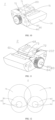
- FIG. 1 is a schematic cross-sectional view of a rotatory shaft kit according to an embodiment of the present disclosure
- FIG. 2 is a perspective schematic view of a partial structure of a rotatory shaft kit according to an embodiment of the present disclosure.
- a rotatory shaft kit 1 the rotatory shaft kit 1 including a rotatory shaft assembly 10, two rotating assemblies 20, and two housing assemblies 30.
- the rotatory shaft assembly 10 includes a protective shell 11, and a first bracket 12 arranged on the protective shell 11.
- a first accommodating space 13 is defined in the first bracket 12.
- One of the two rotating assemblies 20 is arranged on a side of the rotatory shaft assembly 10, and the other of the two rotating assemblies 20 is arranged on another side of the rotatory shaft assembly 10 opposite to the side.
- Each rotating assembly 20 includes a rotating plate 21, a first rotating member 22, and a second rotating member 23; the first rotating member 22 is connected to the rotating plate 21 at an end of the rotating plate 21, and the second rotating member 23 is connected to the rotating plate 21 at another end of the rotating plate 21 opposite to the end.
- the first rotating member 22 is at least partially disposed in the first accommodating space 13 and is capable of rotating relative to the first bracket 12.
- Each housing assembly 30 is arranged on the side of the rotatory shaft assembly 10, and the other of the two housing assemblies 30 is arranged on the another side of the rotatory shaft assembly 10.
- Each housing assembly 30 includes a second bracket 32 and a fixing plate 31 connected to the second bracket 32.
- a second accommodating space 33 is defined in the second bracket 32.
- the second rotating member 23 is at least partially disposed in the second accommodating space 33 and is capable of rotating relative to the second bracket 32.
- the rotatory shaft assembly 10 provided in the present disclosure includes the protective shell 11.
- the protective shell 11 is configured to carry the first bracket 12 and fix the first bracket 12 on the protective shell 11, and further configured to cover the first bracket 12, such that the first bracket 12 is not exposed, thereby preventing damage to the first bracket 12.
- the present disclosure further includes the rotating assemblies 20 arranged on opposite sides of the rotatory shaft assembly 10.
- FIG. 2 only shows the structure of the rotating assembly 20 on one side.
- the structure of the rotating assembly 20 on the other side is similar to the rotating assembly 20 provided in the embodiments and is symmetrically arranged with respect to the rotatory shaft assembly 10.
- Each rotating assembly 20 includes the rotating plate 21, and the rotating plates 21 on the opposite sides are two plates in the four-plate rotatory shaft kit 1.
- the rotating plate 21 may be configured to carry a flexible screen 5 and provide rigid support for the flexible screen 5, and the rotating plate 21 may be further configured to connect the first rotating member 22 and the second rotating member 23, such that the first rotating member 22 and the second rotating member 23 may be carried on the rotating plate 21.
- first rotating member 22 may be at least partially disposed in the first accommodating space 13, such that the first rotating member 22 can rotate relative to the first bracket 12. In this way, through the matching of the first rotating member 22 and the first bracket 12, the rotating assembly 20 can rotate relative to the rotatory shaft assembly 10.
- the present disclosure further includes the housing assemblies 30 arranged on opposite sides of the rotatory shaft assembly 10.
- FIG. 2 only shows the structure of the housing assembly 30 on one side.
- the structure of the housing assembly 30 on the other side is similar to the housing assembly 30 provided in the embodiments and is symmetrically arranged with respect to the rotatory shaft assembly 10.
- Each housing assembly 30 includes the fixing plate 31, and the fixing plates 31 on the opposite sides are the other two plates in the four-plate rotatory shaft kit 1.
- the fixing plate 31 may be configured to carry the flexible screen 5 and provide rigid support for the flexible screen 5, and the fixing plate 31 may be further configured to subsequently connect a housing 4. When the fixing plate 31 rotates, the housing 4 can be driven to rotate together.
- the fixing plate 31 may be further configured to fix and connect the second bracket 32, such that the second bracket 32 may be carried on the fixing plate 31.
- the second rotating member 23 may be at least partially disposed in the second accommodating space 33, and the second rotating member 23 can also rotate relative to the second bracket 32. In this way, through the matching of the second rotating member 23 and the second bracket 32, the housing assembly 30 can rotate relative to the rotating assembly 20, and the housing 4 connected to the housing assembly 30 can also rotate.
- the rotatory shaft kit 1 forms a four-plate shaft assembly structure through the two rotating plates 21 and two fixing plates 31 on opposite sides of the rotatory shaft assembly 10.
- the matching of the first rotating member 22 and the first bracket 12 enables the rotating assembly 20 to rotate relative to the rotatory shaft assembly 10, and the matching of the second rotating member 23 and the second bracket 32 enables the housing assembly 30 to rotate relative to the rotating assembly 20, such that the rotatory shaft kit 1 as a whole can rotate at multiple angles.
- the rotatory shaft kit 1 provided by the present disclosure has a simple structure, and only a few components are needed to realize the rotation of the rotatory shaft kit 1, thereby reducing the accumulated gaps between various components, reducing the size of the resulting size chain, and reducing the amount of falling and scurrying, and improving the quality of the rotatory shaft kit 1.
- a rotation direction of the second rotating member 23 is consistent with a rotation direction of the first rotating member 22, thereby increasing the rotation angle of the rotatory shaft kit 1, such that the rotatory shaft kit 1 can rotate in a wider angle range.
- first bracket 12, the first rotating member 22, the second rotating member 23, and the second bracket 32 may be fixed by defining mounting holes on the protective shell 11, the rotating plate 21, and the fixing plate 31 and by fixing members such as screws.
- a first mounting hole 41 may be defined on the protective shell 11 to fix the first bracket 12 on the protective shell 11.
- a second mounting hole 42 may be defined at the end of the rotating plate 21 to fix the first rotating member 22 on the rotating plate 21.
- a third mounting hole 43 may be defined at the another end of the rotating plate 21 to fix the second rotating member 23 on the rotating plate 21.
- a fourth mounting hole 44 may be defined on the fixing plate 31 to fix the second bracket 32 on the fixing plate 31.
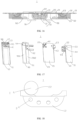
- FIG. 3 is a structural schematic view of a first bracket and a first rotating member according to an embodiment of the present disclosure.
- a first rotating part 14 is arranged on the first bracket 12
- a second rotating part 24 is arranged on the first rotating member 22
- the first rotating part 14 is matched with the second rotating part 24 such that the first rotating member 22 can rotate relative to the first bracket 12.
- the first rotating member 22 can rotate relative to the first bracket 12, and the present disclosure provides two implementations therefor.
- the first rotating part 14 may be arranged on the first bracket 12, and the second rotating part 24 may be arranged on the first rotating member 22, and the first rotating part 14 is matched with the second rotating part 24 such that the first rotating member 22 can rotate relative to the first bracket 12.
- the first rotating part 14 may be a sliding groove or a guide rail
- the second rotating part 24 may be a guide rail or a sliding groove correspondingly.
- the second rotating part 24 may be a sliding groove.
- the second rotating part 24 may be a guide rail.
- the first rotating part 14 as a guide rail and the second rotating part 24 as a sliding groove is taken as an example.
- FIG. 4 is a structural schematic view of a first bracket and a first rotating member according to another embodiment of the present disclosure.
- the rotatory shaft kit 1 further includes a rotating member 15 disposed in the first accommodating space 13 and connected to the first bracket 12, and the first rotating member 22 is sleeved with the rotating member 15 such that the first rotating member 22 can rotate relative to the first bracket 12.
- the first rotating member 22 can rotate relative to the first bracket 12 through the matching of the first rotating part 14 and the second rotating part 24.
- the rotating member 15 may be further arranged on the first bracket 12, and a through hole 25 may be defined on the first rotating member 22.
- the first rotating member 22 is required to be sleeved around the rotating member 15 by the through hole 25 such that the first rotating member 22 can rotate around the rotating member 15, and the first rotating member 22 can thus rotate relative to the first bracket 12.
- the rotating member 15 may further help to mount the first rotating member 22 on the first bracket 12.
- FIG. 5 is a structural schematic view of a second bracket and a second rotating member according to an embodiment of the present disclosure
- FIG. 6 is a structural schematic view of a second bracket and a second rotating member according to another embodiment of the present disclosure.
- the above introduces two implementations in which the first rotating member 22 can rotate relative to the first bracket 12.
- the second rotating member 23 and the second bracket 32 may also have the same structure, such that the second rotating member 23 can rotate relative to the second bracket 32.
- a first rotating part 14 is arranged on the second bracket 32
- a second rotating part 24 is arranged on the second rotating member 23, and the first rotating part 14 is matched with the second rotating part 24 such that the second rotating member 23 can rotate relative to the second bracket 32.
- the rotatory shaft kit 1 further includes a rotating member 15 disposed in the second accommodating space 33 and connected to the second bracket 32, and the second rotating member 23 is sleeved with the rotating member 15 such that the second rotating member 23 can rotate relative to the second bracket 32.
- FIG. 7 is a schematic cross-sectional view of a rotatory shaft kit according to another embodiment of the present disclosure.
- the first rotating members 22 arranged on the opposite sides of the rotatory shaft assembly 10 are specifically a first rotating member (A) 221 and a first rotating member (B) 222 respectively.
- the rotatory shaft kit 1 further includes a first synchronization mechanism 2 connected to the first rotating member (A) 221 and the first rotating member (B) 222, and the first synchronization mechanism 2 is configured to realize a synchronous rotation of the first rotating member (A) 221 with the first rotating member (B) 222.
- the first rotating members 22 on the both sides of the rotatory shaft kit 1 may move independently.
- the first rotating member (A) 221 in FIG. 7 moves, the rotating assembly 20 and the housing assembly 30 on the right side are driven to rotate together.
- the first rotating member (B) 222 on the other side that is, on the left side, may be in a stationary state, such that the rotating assembly 20 and the housing assembly 30 on the left side may also be in a stationary state. It can be understood that it is possible that the right part of the rotatory shaft kit 1 moves while the left part is still in a horizontal state.
- the present disclosure may further introduce the first synchronization mechanism 2 connected to the first rotating member (A) 221 and the first rotating member (B) 222.
- the first rotating member (A) 221 moves, the first rotating member (B) 222 can also move synchronously through the first synchronization mechanism 2, such that the rotating assembly 20 and the housing assembly 30 on opposite sides can be moved simultaneously, which improves the symmetry effect of the rotatory shaft kit 1.
- FIG. 8 is a structural schematic view of a first synchronization mechanism according to an embodiment of the present disclosure
- FIG. 9 is an exploded view of FIG. 8
- FIG. 10 is a structural schematic view of a first sub-bracket, a first internal gear, and a first spur gear shown in FIG. 8
- FIG. 11 is a structural schematic view of a second sub-bracket, a second internal gear, and a second spur gear shown in FIG. 8
- FIG. 12 is a schematic view of a matching of the first sub-bracket, the first internal gear, the first spur gear, and the second spur gear shown in FIG. 8 .
- the first synchronization mechanism 2 includes the first bracket 12, which includes a first sub-bracket 50 and a second sub-bracket 60 that are connected; a first internal gear 70 and a second internal gear 72; and a first spur gear 80 and a second spur gear 83.
- the first sub-bracket 50 defines a first sub-accommodating space 51
- the second sub-bracket 60 defines a second sub-accommodating space 61.
- the first internal gear 70 is arranged in the first rotating member (A) 221, and the first internal gear 70 is arranged in the first sub-accommodating space 51 and is capable of rotating relative to the first sub-bracket 50; the second internal gear 72 is arranged in the first rotating member (B) 222, and the second internal gear 72 is arranged in the second sub-accommodating space 61 and is capable of rotating relative to the second sub-bracket 60.
- the first internal gear 70 defines a first receiving space 71, and the second internal gear 72 defines a second receiving space 73.
- the first spur gear 80 includes a first sub-spur gear 81 arranged in the first receiving space 71 and a second sub-spur gear 82 arranged outside the first receiving space 71.
- the first sub-spur gear 81 is rotatably connected to the first internal gear 70.
- the second spur gear 83 includes a third sub-spur gear 84 arranged in the second receiving space 73 and a fourth sub-spur gear 85 arranged outside the second receiving space 73.
- the third sub-spur gear 84 is rotatably connected to the second internal gear 72
- the fourth sub-spur gear 85 is rotatably connected to the second sub-spur gear 82.
- the first sub-bracket 50 provided in the present disclosure is configured to arrange the first internal gear 70 and the first spur gear 80
- the second sub-bracket 60 is configured to arrange the second internal gear 72 and the second spur gear 83.
- the first sub-bracket 50 and the second sub-bracket 60 are connected, thereby reducing the difficulty of forming a gear pair and reducing the size of the first synchronization mechanism 2.
- the present disclosure further provides the first internal gear 70 and the second internal gear 72.
- the internal gear refers to a gear with teeth on the inner circle.
- the first internal gear 70 is integrated in the first rotating member (A) 221, and the first internal gear 70 is arranged in the first sub-accommodating space 51 and can rotate relative to the first sub-bracket 50.
- a part of the first rotating member (A) 221 is arranged in the first sub-accommodating space 51.
- the second internal gear 72 is further integrated into the first rotating member (B) 222, and the second internal gear 72 is arranged in the second sub-accommodating space 61 and can rotate relative to the second sub-bracket 60.
- a part of the first rotating member (B) 222 is arranged in the second sub-accommodating space 61.
- the first sub-accommodating space 51 is configured to arrange the first internal gear 70, and the first internal gear 70 can rotate relative to the first sub-bracket 50.
- the rotation direction of the first internal gear 70 is consistent with an arrangement direction of the teeth of the first internal gear 70.
- the second sub-accommodating space 61 is configured to arrange the second internal gear 72, and the second internal gear 72 can rotate relative to the second sub-bracket 60.
- the rotation direction of the second internal gear 72 is consistent with an arrangement direction of the teeth of the second internal gear 72.
- the present disclosure further provides the first spur gear 80 and the second spur gear 83.
- the first spur gear 80 includes the first sub-spur gear 81 arranged in the first receiving space 71 and the second sub-spur gear 82 arranged outside the first receiving space 71. It can be understood that since the teeth of the first internal gear 70 are located on the inner circle, a part of the first spur gear 80 is required to be arranged in the first receiving space 71 and rotatably connected with the first internal gear 70 to form a gear pair, and the remaining part of the first spur gear 80 is arranged outside the first receiving space 71.
- the second spur gear 83 may also be understood in the same manner.
- the second spur gear 83 includes the third sub-spur gear 84 arranged in the second receiving space 73 and the third sub-spur gear 84 arranged outside the second receiving space 73. It can be understood that since the teeth of the second internal gear 72 are located on the inner circle, a part of the second spur gear 83 is required to be arranged in the second receiving space 73 and rotatably connected with the second internal gear 72 to form a gear pair, and the remaining part of the second spur gear 83 is arranged outside the second receiving space 73 and is rotatably connected with the remaining part of the first spur gear 80 arranged outside the first receiving space 71. That is, the fourth sub-spur gear 85 is rotatably connected to the second sub-spur gear 82 to form a gear pair.
- the first synchronization mechanism 2 forms three gear pairs by using two internal gears and two spur gears to match with each other. It can also be understood that the first internal gear 70 and the first sub-spur gear 81 constitutes a first gear pair, the second sub-spur gear 82 and the fourth sub-spur gear 85 constitute a second gear pair, and the third sub-spur gear 84 and the second internal gear 72 constitute a third gear pair.
- the first internal gear 70 in the first rotating member (A) 221 rotates, the first internal gear 70 rotates synchronously with the first sub-spur gear 81, and the first sub-spur gear 81 rotates synchronously with the second sub-spur gear 82, the second sub-spur gear 82 rotates synchronously with the fourth sub-spur gear 85, the fourth sub-spur gear 85 rotates synchronously with the third sub-spur gear 84, and the third sub-spur gear 84 rotates synchronously with the second internal gear 72. Since the second internal gear 72 is arranged in the first rotating member (B) 222, and it can be therefore realized that the first rotating member (A) 221 rotates synchronously with the second rotating member 23 (B).
- the first synchronization mechanism 2 provided by the present disclosure has a simple structure. In this way, the synchronous rotation of the first rotating member (A) 221 and the second rotating member 23 (B) may be realized by virtue of the three gear pairs. In addition, the reduction in the number of gear pairs can reduce the accumulated amount of idle travel and improve the synchronization effect of the first synchronization mechanism 2.
- FIG. 13 is a structural schematic view of a first spur gear and a second spur gear according to an embodiment of the present disclosure.
- the diameter of the second sub-spur gear 82 is greater than the diameter of the first sub-spur gear 81; the diameter of the fourth sub-spur gear 85 is greater than the diameter of the third sub-spur gear 84.
- the distance between the first spur gear 80 and the second spur gear 83 may have a slight deviation.
- the first internal gear 70 and the second internal gear 72 rotate 90°
- the diameters of the second sub-spur gear 82 and the first sub-spur gear 81 are the same, and the diameters of the fourth sub-spur gear 85 and the third sub-spur gear 84 are the same, there may be a certain gap between the second sub-spur gear 82 and the fourth sub-spur gear 85, which makes the meshing incomplete.
- the diameter of the second sub-spur gear 82 is greater than the diameter of the first sub-spur gear 81
- the diameter of the fourth sub-spur gear 85 is greater than the diameter of the third sub-spur gear 84, such that regardless of the angle of movement of the first internal gear 70 and the second internal gear 72, the second sub-spur gear 82 and the fourth sub-spur gear 85 can be completely meshed, thereby improving the synchronization effect of the first synchronization mechanism 2.
- FIG. 14 is a structural schematic view of a first sub-bracket and a first spur gear according to an embodiment of the present disclosure.
- the first sub-bracket 50 defines a first through hole 52, and the first spur gear 80 penetrates the first through hole 52.
- the first through hole 52 may be defined on the first sub-bracket 50, and the first spur gear 80 penetrates the first through hole 52 of the first sub-bracket 50, such that the first spur gear 80 is arranged on the first sub-bracket 50, and the first spur gear 80 can rotate relative to the first sub-bracket 50.
- the first through hole 52 may further enable the first sub-spur gear 81 to be rotatably connected with the first internal gear 70 after the first spur gear 80 is arranged. In this way, when the first internal gear 70 moves and rotates, the first sub-spur gear 81 can rotate synchronously, and the second sub-spur gear 82 can rotate synchronously.
- the first through holes 52 may be defined on opposite sides of the first sub-bracket 50 to further improve the installation effect of the first spur gear 80.
- FIG. 15 is a structural schematic view of a first sub-bracket and a second sub-bracket according to an embodiment of the present disclosure.
- the first sub-bracket 50 is arranged with a first positioning part 53
- the second sub-bracket 60 is arranged with a second positioning part 62
- the first positioning part 53 and the second positioning part 62 are matched with each other to connect the first sub-bracket 50 to the second sub-bracket 60.
- the first positioning part 53 may be arranged on the first sub-bracket 50
- the second positioning part 62 may be arranged on the second sub-bracket 60
- the first positioning part 53 and the second positioning part 62 may be disposed opposite to each other.
- the first positioning part 53 and the second positioning part 62 are matched with each other such that the first sub-bracket 50 is connected to the second sub-bracket 60.
- the first positioning part 53 may be a bump or groove 98
- the second positioning part 62 may be a groove 98 or a bump.
- the first positioning part 53 includes a first sub-positioning part 531 and a second sub-positioning part 532 disposed oppositely
- the second positioning part 62 includes a third sub-positioning part 621 and a fourth sub-positioning part 622 disposed oppositely.
- the first sub-positioning part 531 may be a bump and the second sub-positioning part 532 may be a groove 98
- the third sub-positioning part 621 may be a groove 98
- the fourth sub-positioning part 622 may be a bump, which further improves the connection effect of the first sub-bracket 50 and the second sub-bracket 60.
- the present disclosure is only illustrated by the embodiment shown in FIG. 15 , and other embodiments can also achieve the beneficial effects of the present disclosure.
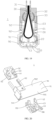
- FIG. 16 is a schematic cross-sectional view of a rotatory shaft kit according to further another embodiment of the present disclosure
- FIG. 17 is a perspective schematic view of a partial structure of the rotatory shaft kit shown in FIG. 16
- FIG. 18 is a schematic view of a rotation center of a compensation assembly of a first bracket and a rotation center of a first rotating member according to an embodiment of the present disclosure
- FIG. 19 is a schematic cross-sectional view of a rotatory shaft kit after being bent according to further another embodiment of the present disclosure.
- the rotatory shaft kit 1 further includes two compensation assemblies 90 arranged on opposite sides of the shaft assembly 10.
- each compensation assembly 90 is rotatably connected to the first bracket 12, and there is a spacing between a rotation center of the compensation assembly 90 (shown by “D” in FIG. 18 ) and a rotation center of the first rotating member 22 (shown by “C” in FIG. 18 ).
- the other end of each compensation assembly 90 is connected to a corresponding housing assembly 30, and the corresponding housing assembly 30 is capable of sliding relative to the compensation assembly 90 such that a distance between the fixing plate 31 and the compensation assembly 90 can be adjusted.
- the flexible screen 5 can be bent to form the flexible electronic device 3.
- the bending manner of the flexible screen 5 is inward folding, there are generally two bending methods: a U-shaped screen and a drop-shaped screen.
- the U-shaped screen will make the overall thickness of the electronic device 3 thicker, while the drop-shaped screen may make the electronic device 3 thinner. Therefore, in the present disclosure, the compensation assembly 90 may be further included in the rotatory shaft kit 1, and the compensation assembly 90 can be matched with other components to make the flexible screen 5 form a drop-shaped screen.
- the end of the compensation assembly 90 may be rotatably connected to the first bracket 12, such that the compensation assembly 90 can rotate relative to the first bracket 12.
- the rotation direction of the compensation assembly 90 is consistent with the rotation direction of the first rotating member 22; and in order to form a drop-shaped screen, there is a spacing between the rotation center of the compensation assembly 90 (shown by "D” in FIG. 18 ) and the rotation center of the first rotating member 22 (shown by "C” in FIG. 18 ). It can also be understood that, as shown in FIG.
- the rotation center of the compensation assembly 90 does not coincide with the rotation center of the first rotating member 22, such that a crank slider movement occurs when the rotatory shaft kit 1 is rotating, thereby causing the first rotating member 22 to rotate differently from the compensation assembly 90, forming a position distance, and finally forming a drop-shaped screen.
- the other end of the compensation assembly 90 may be connected to the corresponding housing assembly 30, and the housing assembly 30 can slide relative to the compensation assembly 90 such that the fixing plate 31 and the compensation assembly 90 can be slid, and the distance between the fixing plate 31 and the compensation assembly 90 is adjustable.
- the compensation housing assembly 30 may be controlled to adjust the distance between the fixing plate 31 and the compensation assembly, thereby ensuring the normal bending of the rotatory shaft kit 1 to form a drop-shaped screen. As illustrated FIGS. 16 and 19 , FIG.
- FIG. 16 is a schematic cross-sectional view of the rotatory shaft kit 1 in a flattened state, and in this case, the total length of the compensation assembly 90 and the housing assembly 30 is a first length;
- FIG. 19 is a schematic cross-sectional view of the rotatory shaft kit 1 after a 90° movement, in this case, the housing assembly 30 slides relative to the compensation assembly 90 due to the movement of the crank slider, and the total length of the compensation assembly 90 and the housing assembly 30 is a second length. The second length is greater than the first length.
- FIG. 20 is a structural schematic view of a compensation assembly, a first bracket, and a second bracket according to an embodiment of the present disclosure.
- the compensation assembly 90 includes a compensation plate 91.
- the compensation plate 91 includes a first end 901 and a second end 902 that are opposed to each other.
- the first end 901 is arranged with a third rotating part 94.
- a fourth rotating part 95 is arranged on the first bracket 12, and the third rotating part 94 is matched with the fourth rotating part 95 to enable the compensation plate 91 to rotate relative to the first bracket 12.
- the compensation assembly 90 provided by the present disclosure includes the compensation plate 91.
- the compensation plate 91 is configured to arrange the third rotating part 94, and the compensation assembly 90 may be matched with the housing 4 of the electronic device 3 to form a shell of the electronic device 3.
- the compensation plate 91 is not counted as a plate in the four-plate rotatory shaft kit 1.
- the third rotating part 94 may be arranged on the first end 901 of the compensation plate 91, and the fourth rotating part 95 may be arranged on the first bracket 12.
- the third rotating part 94 can be matched with the fourth rotating part 95 such that the compensation plate 91 can rotate relative to the first bracket 12.
- the third rotating part 94 may be a bump or a via hole
- the fourth rotating part 95 may be a via hole or a bump.
- the fourth rotating part 95 may be a via hole.
- the third rotating part 94 is a via hole
- the fourth rotating part 95 may be a bump.
- the third rotating part 94 as a bump and the fourth rotating part 95 as a via hole are taken as an example for description.
- the second end 902 may be arranged with a first sliding part 92
- the second bracket 32 may be arranged a second sliding part 93
- the first sliding part 92 and the second sliding part 93 are matched such that the distance between the compensation plate 91 and the fixing plate 31 can be adjusted.
- the first sliding part 92 may be arranged on the second end 902 of the compensation plate 91, and the second sliding part 93 may be arranged on the second bracket 32.
- the first sliding part 92 and the second sliding part 93 are matched with each other to make the distance between the compensation plate 91 and the fixing plate 31 adjustable.
- the first sliding part 92 may be a sliding groove or a sliding rail
- the second sliding part 93 may be a sliding rail or a sliding groove.
- the second sliding part 93 may be a sliding rail.
- the second sliding part 93 may be a sliding groove.
- the first sliding part 92 as a sliding groove and the second sliding part 93 as a sliding rail are taken as an example for description.
- a sliding groove is arranged and the sliding groove is fixed on the compensation plate 91, and sliding rails are arranged protruding from the opposite sides of the second bracket 32, such that the second bracket 32 can slide along the sliding groove to change the distance between the compensation plate 91 and the fixing plate 31.
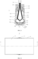
- FIG. 21 is a schematic cross-sectional view of a rotatory shaft kit according to further another embodiment of the present disclosure.
- the rotatory shaft kit 1 further includes a second synchronization mechanism, and the second synchronization mechanism includes first gears 96 arranged on the third rotating part 94 or the fourth rotating part 95, and a gear set 97 arranged on the first bracket 12 and rotatably connected to the first gears 96.
- the compensation assembly 90 arranged on a side of the rotatory shaft assembly 10 rotates, a corresponding first gear 96 and the gear set 97 are matched with each other, such that the compensation assemblies 90 on the opposite sides of the rotatory shaft assembly 10 rotate synchronously.
- the first synchronization mechanism 2 may be further included in the rotatory shaft kit 1 such that the first rotating members 22 on the opposite sides rotate synchronously, thereby driving the rotating assemblies 20 and the housing assemblies 30 on the opposite sides to rotate synchronously.
- the second synchronization mechanism may enable the compensation assemblies 90 on the opposite sides to rotate synchronously, thereby forming a better drop-shaped screen.
- the first gears 96 may be provided on the third rotating part 94 or the fourth rotating part 95. Since the compensation assemblies 90 are provided on opposite sides, that is, the number of the compensation assemblies 90 is two, the number of the first gear 96 is also two, and the two first gears are arranged opposite to each other.
- the gear set 97 is arranged on the first bracket 12, that is, the gear set 97 is arranged between the two first gears 96, such that the gear set 97 rotates and connects the first gears 96 on the opposite sides at the same time.
- the compensation assemblies 90 on the opposite sides can rotate synchronously.
- the first gear 96 on the side may be driven to rotate by the third rotating part 94 or the fourth rotating part 95, and the first gear 96 drives the gear set 97 to rotate synchronously.
- the gear set 97 drives the first gear 96 on the other side to rotate synchronously, and the first gear 96 on the other side drives the compensation assembly 90 on the other side to rotate, and finally causes the compensation assemblies 90 on the opposite sides to rotate synchronously.
- the gear set 97 includes two gears.
- the first gear 96 and the gear set 97 may be arranged in a groove 98 defined on the first bracket 12 (as shown in FIG. 17 or FIG. 20 ).
- the embodiments of the present disclosure further provides an electronic device 3. Both the electronic device 3 and the rotatory shaft kit 1 provided in the present disclosure can achieve the advantages of the present disclosure. In some embodiments, the rotatory shaft kit 1 provided above may be adopted to form the electronic device 3 below.
- FIG. 22 is a structural schematic view of an electronic device according to an embodiment of the present disclosure
- FIG. 23 is a schematic cross-sectional view of FIG. 22 along an A-A direction
- FIG. 24 is an exploded schematic view of a partially structure of the electronic device shown in FIG. 22 after a flexible screen is removed
- FIG. 25 is a structural schematic view of an electronic device after a movement according to an embodiment of the present disclosure
- FIG. 26 is a cross-sectional schematic view of an electronic device after a movement according to an embodiment of the present disclosure.
- the embodiments further provide an electronic device 3.
- the electronic device 3 includes a housing 4, a flexible screen 5, and the rotatory shaft kit 1 provided in the above embodiments of the present disclosure.
- the flexible screen 5 is arranged on the housing 4.
- the housing 4 includes a first sub-housing 401 and a second sub-housing 402 disposed oppositely.
- the first sub-housing 401 is connected to the housing assembly 30 on a side of the rotatory shaft kit 1
- the second sub-housing 402 is connected to the housing assembly 30 on the other side of the rotatory shaft kit 1.
- the electronic device 3 includes, but is not limited to, mobile phones, tablet computers, notebook computers, handheld computers, personal computers (PCs), personal digital assistants (PDAs), portable media players (PMPs), navigation devices, wearable devices, smart bracelets, pedometers and other mobile terminals, and fixed terminals such as digital TVs, desktop computers, etc.
- PCs personal computers
- PDAs personal digital assistants
- PMPs portable media players
- navigation devices wearable devices
- smart bracelets smart bracelets
- pedometers pedometers and other mobile terminals
- fixed terminals such as digital TVs, desktop computers, etc.
- the flexible screen 5 may be arranged on the housing 4.
- the flexible screen 5 is also arranged on the rotatory shaft kit 1 such that the flexible screen 5 can be folded inward, thereby forming a drop-shaped screen. It can be seen from the above that when the rotatory shaft kit 1 includes the rotatory shaft assembly 10, the rotating assembly 20, and the housing assembly 30, the rotatory shaft kit 1 can be bent, thereby driving the housing 4 connected to the housing assembly 30 to bend and further driving the flexible screen 5 to bend to form a U-shaped screen.
- the rotatory shaft kit 1 further includes the compensation assembly 90
- the rotating assembly 20 and the housing assembly 30 are kept at an angle tilt, which can also be understood as when the housing 4 rotates by 90°, the rotating assembly 20 and the housing assembly 30 can rotate more than 90°, such that the flexible screen 5 presents the effect of drop-shaped when the flexible screen 5 is bent.
- the housing assembly 30 is rotated in an opposite direction of the rotation direction relative to the rotating assembly 20, such that the distance between opposite ends of the flexible screen 5 is reduced, and a drop-shaped screen is further formed (as shown in FIG. 26 ).
- the electronic device 3 provided in the present disclosure by using the rotatory shaft kit 1 provided in the above embodiments of the present disclosure, can reduce the accumulation of gaps between the various components in the rotatory shaft kit 1, thereby reducing the size of the resulting size chain and reducing the amount of falling and scurrying, which improves the quality of the rotatory shaft kit 1 and the electronic device 3.
- the rotatory shaft kit 1 includes a rotatory shaft assembly 10, the rotatory shaft assembly 10 includes a first bracket 12, and a side of the first bracket 12 close to the flexible screen 5 defines an avoiding groove 6, and the avoiding groove 6 is configured to receive a part of the flexible screen 5 when the electronic device 3 is bent.
- the escape groove 6 may be defined on the first bracket 12, and it can also be understood that the escape groove 6 is defined on a side surface of the first bracket 12 close to the flexible screen 5. In this way, when the flexible screen 5 is bent, the avoiding groove 6 can accommodate a part of the flexible screen 5 which is displaced toward the first bracket 12, so as to prevent the flexible screen 5 from colliding with the first bracket 12 when the flexible screen 5 is bent.
Landscapes
- Engineering & Computer Science (AREA)
- General Engineering & Computer Science (AREA)
- Theoretical Computer Science (AREA)
- Computer Hardware Design (AREA)
- Physics & Mathematics (AREA)
- General Physics & Mathematics (AREA)
- Human Computer Interaction (AREA)
- Mechanical Engineering (AREA)
- Mathematical Physics (AREA)
- Signal Processing (AREA)
- Telephone Set Structure (AREA)
- Transmission Devices (AREA)
- Pivots And Pivotal Connections (AREA)
Claims (14)
- Drehwellenbaugruppe (1), die Folgendes umfasst:eine Drehwellenanordnung (10), die eine Schutzhülle (11) und einen ersten Haltebügel (12), der an der Schutzhülle (11) angeordnet ist, umfasst; wobei im ersten Haltebügel (12) ein erster Aufnahmeraum (13) definiert ist;zwei Drehanordnungen (20); wobei eine der zwei Drehanordnungen (20) auf einer Seite der Drehwellenanordnung (10) angeordnet ist und die weitere der zwei Drehanordnungen (20) auf einer weiteren Seite der Drehwellenanordnung (10), die der einen Seite gegenüberliegt, angeordnet ist; jede Drehanordnung (20) einen Drehteller (21), ein erstes Drehelement (22) und ein zweites Drehelement (23) umfasst; das erste Drehelement (22) mit dem Drehteller (21) bei einem Ende des Drehtellers (21) verbunden ist und das zweite Drehelement (23) mit dem Drehteller (21) bei einem weiteren Ende des Drehtellers (21), das dem einen Ende gegenüberliegt, verbunden ist und das erste Drehelement (22) mindestens teilweise im ersten Aufnahmeraum (13) angeordnet ist und in Bezug auf den ersten Haltebügel (12) drehbar ist; undzwei Gehäuseanordnungen (30); wobei eine der zwei Gehäuseanordnungen (30) auf der Seite der Drehwellenanordnung (10) angeordnet ist und die weitere der zwei Gehäuseanordnungen (30) auf der weiteren Seite der Drehwellenanordnung (10) angeordnet ist; jede Gehäuseanordnung (30) einen zweiten Haltebügel (32) und eine Befestigungsplatte (31), die mit dem zweiten Haltebügel (32) verbunden ist, umfasst; im zweiten Haltebügel (32) ein zweiter Aufnahmeraum (33) definiert ist und das zweite Drehelement (23) mindestens teilweise im zweiten Aufnahmeraum (33) angeordnet ist und in Bezug auf den zweiten Haltebügel (32) drehbar ist;ferner gekennzeichnet durchzwei Ausgleichsanordnungen (90);wobei eine der zwei Ausgleichsanordnungen (90) auf der Seite der Drehwellenanordnung (10) angeordnet ist und die weitere der zwei Ausgleichsanordnungen (90) auf der weiteren Seite der Drehwellenanordnung (10) angeordnet ist; ein Ende jeder Ausgleichsanordnung (90) mit dem ersten Haltebügel (12) drehbar verbunden ist und ein Abstand zwischen einem Drehzentrum jeder Ausgleichsanordnung (90) und einem Drehzentrum eines entsprechenden ersten Drehelements (22) vorhanden ist; das weitere Ende jeder Ausgleichsanordnung (90) mit einer entsprechenden Gehäuseanordnung (30) verbunden ist und die entsprechende Gehäuseanordnung (30) in Bezug auf die jeweilige Ausgleichsanordnung (90) schiebbar ist, derart, dass eine Entfernung zwischen der Befestigungsplatte (31) und der Ausgleichsanordnung (90) einstellbar ist; jede Ausgleichsanordnung (90) eine Ausgleichsplatte (91) umfasst und die Ausgleichsplatte (91) ein erstes Ende (901) und ein zweites Ende (902), die einander gegenüberliegen, umfasst.
- Drehwellenbaugruppe (1) nach Anspruch 1, wobei eine Drehrichtung des zweiten Drehelements (23) mit einer Drehrichtung des ersten Drehelements (22) konsistent ist.
- Drehwellenbaugruppe (1) nach Anspruch 1, wobei ein erster Drehabschnitt (14) am ersten Haltebügel (12) angeordnet ist, ein zweiter Drehabschnitt (24) am ersten Drehelement (22) angeordnet ist und der erste Drehabschnitt (14) mit dem zweiten Drehabschnitt (24) abgestimmt ist, derart, dass das erste Drehelement (22) in Bezug auf den ersten Haltebügel (12) drehbar ist.
- Drehwellenbaugruppe (1) nach Anspruch 3, wobei am zweiten Haltebügel (32) ein weiterer erster Drehabschnitt (14) angeordnet ist, am zweiten Drehelement (23) ein weiterer zweiter Drehabschnitt (24) angeordnet ist und der weitere erste Drehabschnitt (14) mit dem weiteren zweiten Drehabschnitt (24) abgestimmt ist, derart, dass das zweite Drehelement (23) in Bezug auf den zweiten Haltebügel (32) drehbar ist.
- Drehwellenbaugruppe (1) nach Anspruch 1, die ferner ein Drehelement (15) umfasst, das im ersten Aufnahmeraum (13) angeordnet ist und mit dem ersten Haltebügel (12) verbunden ist, wobei das erste Drehelement (22) mit dem Drehelement (15) ummantelt ist, derart, dass das erste Drehelement (22) in Bezug auf den ersten Haltebügel (12) drehbar ist.
- Drehwellenbaugruppe (1) nach Anspruch 5, die ferner ein weiteres Drehelement (15) umfasst, das im zweiten Aufnahmeraum (33) angeordnet ist und mit dem zweiten Haltebügel (32) verbunden ist, wobei das zweite Drehelement (23) mit dem weiteren Drehelement (15) ummantelt ist, derart, dass das zweite Drehelement (23) in Bezug auf den zweiten Haltebügel (32) drehbar ist.
- Drehwellenbaugruppe (1) nach Anspruch 1, wobei die zwei ersten Drehelemente (22), die auf den gegenüberliegenden Seiten der Drehwellenanordnung (10) angeordnet sind, ein erstes Drehelement A bzw. ein erstes Drehelement B sind; die Drehwellenbaugruppe (1) ferner einen ersten Synchronisationsmechanismus (2) umfasst, der mit dem ersten Drehelement A und dem ersten Drehelement B verbunden ist, und der erste Synchronisationsmechanismus (2) konfiguriert ist, eine synchrone Drehung des ersten Drehelements A mit dem ersten Drehelement B zu realisieren.
- Drehwellenbaugruppe (1) nach Anspruch 7, wobei der erste Synchronisationsmechanismus (2) Folgendes umfasst:den ersten Haltebügel (12), der einen ersten Unterhaltebügel (50) und einen zweiten Unterhaltebügel (60) umfasst, die verbunden sind; wobei der erste Unterhaltebügel (50) einen ersten Unteraufnahmeraum (51) definiert und der zweite Unterhaltebügel (60) einen zweiten Unteraufnahmeraum (61) definiert;ein erstes Innenzahnrad (70) und ein zweites Innenzahnrad (72); wobei das erste Innenzahnrad (70) im ersten Drehelement A angeordnet ist und das erste Innenzahnrad (70) im ersten Unteraufnahmeraum (51) angeordnet ist und in Bezug auf den ersten Unterhaltebügel (50) drehbar ist; das zweite Innenzahnrad (72) im ersten Drehelement B angeordnet ist und das zweite Innenzahnrad (72) im zweiten Unteraufnahmeraum (61) angeordnet ist und in Bezug auf den zweiten Unterhaltebügel (60) drehbar ist; das erste Innenzahnrad (70) einen ersten Aufnahmeraum (71) definiert und das zweite Innenzahnrad (72) einen zweiten Aufnahmeraum (73) definiert; undein erstes Stirnrad (80) und ein zweites Stirnrad (83); wobei das erste Stirnrad (80) ein erstes Unterstirnrad (81), das im ersten Aufnahmeraum (71) angeordnet ist, und ein zweites Unterstirnrad (82), das außerhalb des ersten Aufnahmeraums (71) angeordnet ist, umfasst; das erste Unterstirnrad (81) mit dem ersten Innenzahnrad (70) drehbar verbunden ist; das zweite Stirnrad (83) ein drittes Unterstirnrad (84), das im zweiten Aufnahmeraum (73) angeordnet ist, und ein viertes Unterstirnrad (85), das außerhalb des zweiten Aufnahmeraums (73) angeordnet ist, umfasst; das dritte Unterstirnrad (84) mit dem zweiten Innenzahnrad (72) drehbar verbunden ist und das vierte Unterstirnrad (85) mit dem zweiten Unterstirnrad (82) drehbar verbunden ist; und in Reaktion darauf, dass das erste Drehelement A sich dreht, das erste Innenzahnrad (70), das zweite Innenzahnrad (72), das erste Stirnrad (80) und das zweite Stirnrad (83) aufeinander abgestimmt werden, um zu verursachen, dass das erste Drehelement A und das erste Drehelement B sich synchron drehen.
- Drehwellenbaugruppe (1) nach Anspruch 8, wobei der erste Unterhaltebügel (50) ein erstes Durchgangsloch (52) definiert und das erste Stirnrad (80) das erste Durchgangsloch (52) durchdringt.
- Drehwellenbaugruppe (1) nach Anspruch 8, wobei der erste Unterhaltebügel (50) mit einem ersten Positionierungsabschnitt (53) angeordnet ist, der zweite Unterhaltebügel (60) mit einem zweiten Positionierungsabschnitt (62) angeordnet ist und der erste Positionierungsabschnitt (53) und der zweite Positionierungsabschnitt (62) aufeinander abgestimmt sind, um den ersten Unterhaltebügel (50) mit dem zweiten Unterhaltebügel (60) zu verbinden.
- Drehwellenbaugruppe (1) nach Anspruch 1, wobei das erste Ende (901) mit einem dritten Drehabschnitt (94) angeordnet ist, ein vierter Drehabschnitt (95) am ersten Haltebügel (12) angeordnet ist und der dritte Drehabschnitt (94) mit dem vierten Drehabschnitt (95) abgestimmt ist, derart, dass die Ausgleichsplatte (91) in Bezug auf den ersten Haltebügel (12) drehbar ist.
- Drehwellenbaugruppe (1) nach Anspruch 11, die ferner einen zweiten Synchronisationsmechanismus umfasst; wobei der zweite Synchronisationsmechanismus zwei erste Zahnräder (96), die jeweils an dem dritten Drehabschnitt (94) oder dem vierten Drehabschnitt (95) angeordnet sind, und einen Zahnradsatz (97), der an dem ersten Haltebügel (12) angeordnet ist und mit den zwei ersten Zahnrädern (96) drehbar verbunden ist, umfasst; und in Reaktion darauf, dass sich jede Ausgleichsanordnung (90) dreht, ein entsprechendes erstes Zahnrad (96) und der Zahnradsatz (97) aufeinander abgestimmt werden, derart, dass die zwei Ausgleichsanordnungen (90) sich synchron drehen.
- Drehwellenbaugruppe (1) nach Anspruch 1, wobei das zweite Ende (902) mit einem ersten Gleitabschnitt (92) angeordnet ist, der zweite Haltebügel (32) mit einem zweiten Gleitabschnitt (93) angeordnet ist und der erste Gleitabschnitt (92) und der zweite Gleitabschnitt (93) abgestimmt sind, derart, dass eine Entfernung zwischen der Ausgleichsplatte (91) und der Befestigungsplatte (31) einstellbar ist.
- Elektronische Vorrichtung (3), die ein Gehäuse (4), einen flexiblen Bildschirm (5) und die Drehwellenbaugruppe (1) nach einem der Ansprüche 1-13 umfasst; wobei der flexible Bildschirm (5) am Gehäuse (4) angeordnet ist; das Gehäuse (4) ein erstes Untergehäuse (401) und ein zweites Untergehäuse (402), die entgegengesetzt angeordnet sind, umfasst; das erste Untergehäuse (401) mit einer der Gehäuseanordnungen (30), die auf der Seite der Drehwellenbaugruppe (1) angeordnet ist, verbunden ist und das zweite Untergehäuse (402) mit der weiteren der zwei Gehäuseanordnungen (30), die auf der weiteren Seite der Drehwellenbaugruppe (1) angeordnet ist, verbunden ist.
Applications Claiming Priority (2)
| Application Number | Priority Date | Filing Date | Title |
|---|---|---|---|
| CN202010371340.0A CN113586595B (zh) | 2020-04-30 | 2020-04-30 | 转轴套件、电子设备 |
| PCT/CN2021/078683 WO2021218358A1 (zh) | 2020-04-30 | 2021-03-02 | 转轴套件、电子设备 |
Publications (3)
| Publication Number | Publication Date |
|---|---|
| EP4145808A1 EP4145808A1 (de) | 2023-03-08 |
| EP4145808A4 EP4145808A4 (de) | 2023-11-01 |
| EP4145808B1 true EP4145808B1 (de) | 2024-08-07 |
Family
ID=78237909
Family Applications (1)
| Application Number | Title | Priority Date | Filing Date |
|---|---|---|---|
| EP21795503.8A Active EP4145808B1 (de) | 2020-04-30 | 2021-03-02 | Drehwellenkit und elektronische vorrichtung |
Country Status (4)
| Country | Link |
|---|---|
| US (1) | US12147276B2 (de) |
| EP (1) | EP4145808B1 (de) |
| CN (2) | CN115059684B (de) |
| WO (1) | WO2021218358A1 (de) |
Cited By (1)
| Publication number | Priority date | Publication date | Assignee | Title |
|---|---|---|---|---|
| US12222772B2 (en) * | 2020-09-17 | 2025-02-11 | Guangdong Oppo Mobile Telecommunications Corp., Ltd. | Rotating shaft mechanism and foldable electronic device |
Families Citing this family (7)
| Publication number | Priority date | Publication date | Assignee | Title |
|---|---|---|---|---|
| CN113586594B (zh) * | 2020-04-30 | 2022-06-07 | Oppo广东移动通信有限公司 | 电子组件、电子设备 |
| CN120969349A (zh) * | 2021-12-31 | 2025-11-18 | Oppo广东移动通信有限公司 | 转轴组件、电子设备 |
| TWI803201B (zh) * | 2022-02-21 | 2023-05-21 | 富世達股份有限公司 | 鉸鏈 |
| CN116928202A (zh) * | 2022-03-31 | 2023-10-24 | 北京小米移动软件有限公司 | 转轴装置及折叠式电子设备 |
| CN114810805B (zh) * | 2022-05-17 | 2023-05-02 | 武汉华星光电半导体显示技术有限公司 | 铰链、显示面板及移动终端 |
| CN116320116A (zh) * | 2023-03-27 | 2023-06-23 | 联想(北京)有限公司 | 电子设备 |
| CN120159855B (zh) * | 2023-04-27 | 2025-12-05 | 华为技术有限公司 | 一种转轴机构及电子设备 |
Family Cites Families (28)
| Publication number | Priority date | Publication date | Assignee | Title |
|---|---|---|---|---|
| JP2002168231A (ja) * | 2000-11-30 | 2002-06-14 | Sugatsune Ind Co Ltd | 回動連結構造及びヒンジ |
| US8804349B2 (en) * | 2012-10-19 | 2014-08-12 | Samsung Display Co., Ltd. | Foldable display device |
| KR102233119B1 (ko) * | 2014-09-23 | 2021-03-30 | 삼성디스플레이 주식회사 | 표시장치 |
| KR102322377B1 (ko) * | 2014-12-31 | 2021-11-05 | 엘지디스플레이 주식회사 | 접이식 디스플레이 장치 |
| US10551880B1 (en) * | 2015-09-11 | 2020-02-04 | Apple Inc. | Electronic devices with flexible displays and hinges |
| CN108076171B (zh) * | 2016-11-17 | 2020-04-03 | 华为技术有限公司 | 折叠组件及移动终端 |
| TWM550964U (zh) * | 2017-08-07 | 2017-10-21 | First Dome Corp | 薄型鉸鏈 |
| WO2019107854A1 (en) * | 2017-11-28 | 2019-06-06 | Samsung Electronics Co., Ltd. | Foldable display device |
| KR102397575B1 (ko) * | 2017-12-01 | 2022-05-13 | 삼성전자주식회사 | 힌지 구조를 포함하는 전자 장치 |
| KR102430043B1 (ko) * | 2017-12-04 | 2022-08-04 | 엘지디스플레이 주식회사 | 폴더블 디스플레이 장치 |
| TWI673545B (zh) * | 2018-06-21 | 2019-10-01 | 兆利科技工業股份有限公司 | 折疊式裝置的轉軸模組 |
| CN208656822U (zh) * | 2018-07-13 | 2019-03-26 | Oppo广东移动通信有限公司 | 折叠装置及电子设备 |
| CN110714977B (zh) * | 2018-07-13 | 2025-03-14 | Oppo广东移动通信有限公司 | 折叠装置及电子设备 |
| TWI687795B (zh) * | 2018-09-27 | 2020-03-11 | 兆利科技工業股份有限公司 | 折疊式裝置的轉軸模組 |
| CN209390110U (zh) * | 2018-10-26 | 2019-09-13 | Oppo广东移动通信有限公司 | 电子设备 |
| CN109780403B (zh) * | 2019-01-29 | 2020-08-18 | 维沃移动通信有限公司 | 转动连接组件及折叠式终端设备 |
| CN114519960B (zh) * | 2019-02-25 | 2024-04-02 | Oppo广东移动通信有限公司 | 转动装置、壳体及电子装置 |
| CN209514482U (zh) * | 2019-04-08 | 2019-10-18 | 东莞市劲丰电子有限公司 | 实现屏内折的水滴形同步转动机构 |
| CN111862798B (zh) * | 2019-04-25 | 2021-06-15 | Oppo广东移动通信有限公司 | 柔性显示装置及电子装置 |
| CN110030255A (zh) | 2019-05-07 | 2019-07-19 | 东莞市劲丰电子有限公司 | 四板水滴形内折同步转动机构 |
| TWI703428B (zh) * | 2019-05-21 | 2020-09-01 | 兆利科技工業股份有限公司 | 多折式裝置的折疊長度差補償機構 |
| CN110273915B (zh) * | 2019-06-25 | 2020-10-09 | 昆山国显光电有限公司 | 柔性屏的支撑装置、可折叠的显示模组及显示设备 |
| CN110784570B (zh) * | 2019-10-29 | 2021-04-09 | Oppo广东移动通信有限公司 | 折叠装置及电子设备 |
| CN210377243U (zh) * | 2019-10-30 | 2020-04-21 | Oppo广东移动通信有限公司 | 电子设备 |
| CN110995892B (zh) * | 2019-10-31 | 2021-10-26 | 华为终端有限公司 | 电子设备 |
| TWI714385B (zh) * | 2019-12-09 | 2020-12-21 | 富世達股份有限公司 | 同動式鉸鏈 |
| US12314088B2 (en) * | 2021-07-22 | 2025-05-27 | Samsung Electronics Co., Ltd. | Hinge apparatus and electronic device including the same |
| US12396112B2 (en) * | 2021-12-31 | 2025-08-19 | Lg Display Co., Ltd. | Foldable display apparatus |
-
2020
- 2020-04-30 CN CN202210844701.8A patent/CN115059684B/zh active Active
- 2020-04-30 CN CN202010371340.0A patent/CN113586595B/zh active Active
-
2021
- 2021-03-02 WO PCT/CN2021/078683 patent/WO2021218358A1/zh not_active Ceased
- 2021-03-02 EP EP21795503.8A patent/EP4145808B1/de active Active
-
2022
- 2022-10-28 US US17/976,637 patent/US12147276B2/en active Active
Cited By (1)
| Publication number | Priority date | Publication date | Assignee | Title |
|---|---|---|---|---|
| US12222772B2 (en) * | 2020-09-17 | 2025-02-11 | Guangdong Oppo Mobile Telecommunications Corp., Ltd. | Rotating shaft mechanism and foldable electronic device |
Also Published As
| Publication number | Publication date |
|---|---|
| WO2021218358A1 (zh) | 2021-11-04 |
| US12147276B2 (en) | 2024-11-19 |
| CN115059684A (zh) | 2022-09-16 |
| CN113586595B (zh) | 2022-08-09 |
| EP4145808A4 (de) | 2023-11-01 |
| CN115059684B (zh) | 2024-05-10 |
| EP4145808A1 (de) | 2023-03-08 |
| US20230049603A1 (en) | 2023-02-16 |
| CN113586595A (zh) | 2021-11-02 |
Similar Documents
| Publication | Publication Date | Title |
|---|---|---|
| US12147276B2 (en) | Rotary shaft kit and electronic device | |
| US11455017B2 (en) | Hinge for mobile terminal having an inwardly bendable flexible screen and mobile terminal having an inwardly bendable flexible screen | |
| EP4099666B1 (de) | Elektronische anordnung und elektronische vorrichtung | |
| EP4329274A1 (de) | Faltschirmvorrichtung | |
| CN115370655A (zh) | 转动模组和电子设备 | |
| US20240019911A1 (en) | Hinge component and electronic device | |
| EP4180677B1 (de) | Drehwellenmechanismus und elektronische vorrichtung | |
| CN111246697B (zh) | 转轴组件、显示模组及显示设备 | |
| CN116498642B (zh) | 一种同步机构、转轴机构和电子设备 | |
| WO2023071130A1 (zh) | 铰链装置及折叠式电子设备 | |
| CN219673084U (zh) | 电子设备 | |
| CN211702091U (zh) | 一种360°铰链及移动终端 | |
| KR101686141B1 (ko) | 이축 슬라이드 장치 및 이를 구비하는 전자기기 | |
| WO2024222240A1 (zh) | 一种转轴机构及电子设备 | |
| CN118934819A (zh) | 折叠装置、壳体组件和电子设备 | |
| CN118869849A (zh) | 折叠装置、壳体组件和电子设备 | |
| CN119071376A (zh) | 折叠装置、壳体组件和电子设备 | |
| CN221652625U (zh) | 折叠装置、壳体组件和电子设备 | |
| CN119676340A (zh) | 折叠装置、壳体组件和电子设备 | |
| EP4661378A1 (de) | Drehwellenmechanismus und elektronische vorrichtung | |
| CN113586593A (zh) | 同步机构、转轴套件、电子设备 | |
| CN120720328A (zh) | 铰链组件和电子设备 | |
| WO2026090939A1 (zh) | 一种铰链组件以及电子设备 | |
| CN118582456A (zh) | 电子设备 | |
| CN118361450A (zh) | 折叠装置、壳体组件和电子设备 |
Legal Events
| Date | Code | Title | Description |
|---|---|---|---|
| STAA | Information on the status of an ep patent application or granted ep patent |
Free format text: STATUS: THE INTERNATIONAL PUBLICATION HAS BEEN MADE |
|
| PUAI | Public reference made under article 153(3) epc to a published international application that has entered the european phase |
Free format text: ORIGINAL CODE: 0009012 |
|
| STAA | Information on the status of an ep patent application or granted ep patent |
Free format text: STATUS: REQUEST FOR EXAMINATION WAS MADE |
|
| 17P | Request for examination filed |
Effective date: 20221129 |
|
| AK | Designated contracting states |
Kind code of ref document: A1 Designated state(s): AL AT BE BG CH CY CZ DE DK EE ES FI FR GB GR HR HU IE IS IT LI LT LU LV MC MK MT NL NO PL PT RO RS SE SI SK SM TR |
|
| DAV | Request for validation of the european patent (deleted) | ||
| DAX | Request for extension of the european patent (deleted) | ||
| A4 | Supplementary search report drawn up and despatched |
Effective date: 20230928 |
|
| RIC1 | Information provided on ipc code assigned before grant |
Ipc: G06F 1/16 20060101ALI20230922BHEP Ipc: F16C 11/04 20060101ALI20230922BHEP Ipc: G05F 1/16 20060101ALI20230922BHEP Ipc: H04M 1/02 20060101AFI20230922BHEP |
|
| GRAP | Despatch of communication of intention to grant a patent |
Free format text: ORIGINAL CODE: EPIDOSNIGR1 |
|
| STAA | Information on the status of an ep patent application or granted ep patent |
Free format text: STATUS: GRANT OF PATENT IS INTENDED |
|
| RIC1 | Information provided on ipc code assigned before grant |
Ipc: G06F 1/16 20060101ALI20240430BHEP Ipc: F16C 11/04 20060101ALI20240430BHEP Ipc: G05F 1/16 20060101ALI20240430BHEP Ipc: H04M 1/02 20060101AFI20240430BHEP |
|
| INTG | Intention to grant announced |
Effective date: 20240524 |
|
| GRAS | Grant fee paid |
Free format text: ORIGINAL CODE: EPIDOSNIGR3 |
|
| GRAA | (expected) grant |
Free format text: ORIGINAL CODE: 0009210 |
|
| STAA | Information on the status of an ep patent application or granted ep patent |
Free format text: STATUS: THE PATENT HAS BEEN GRANTED |
|
| AK | Designated contracting states |
Kind code of ref document: B1 Designated state(s): AL AT BE BG CH CY CZ DE DK EE ES FI FR GB GR HR HU IE IS IT LI LT LU LV MC MK MT NL NO PL PT RO RS SE SI SK SM TR |
|
| REG | Reference to a national code |
Ref country code: GB Ref legal event code: FG4D |
|
| REG | Reference to a national code |
Ref country code: CH Ref legal event code: EP |
|
| REG | Reference to a national code |
Ref country code: IE Ref legal event code: FG4D |
|
| REG | Reference to a national code |
Ref country code: DE Ref legal event code: R096 Ref document number: 602021016978 Country of ref document: DE |
|
| P01 | Opt-out of the competence of the unified patent court (upc) registered |
Free format text: CASE NUMBER: APP_49614/2024 Effective date: 20240902 |
|
| REG | Reference to a national code |
Ref country code: LT Ref legal event code: MG9D |
|
| REG | Reference to a national code |
Ref country code: NL Ref legal event code: MP Effective date: 20240807 |
|
| PG25 | Lapsed in a contracting state [announced via postgrant information from national office to epo] |
Ref country code: NO Free format text: LAPSE BECAUSE OF FAILURE TO SUBMIT A TRANSLATION OF THE DESCRIPTION OR TO PAY THE FEE WITHIN THE PRESCRIBED TIME-LIMIT Effective date: 20241107 |
|
| REG | Reference to a national code |
Ref country code: AT Ref legal event code: MK05 Ref document number: 1712159 Country of ref document: AT Kind code of ref document: T Effective date: 20240807 |
|
| PG25 | Lapsed in a contracting state [announced via postgrant information from national office to epo] |
Ref country code: GR Free format text: LAPSE BECAUSE OF FAILURE TO SUBMIT A TRANSLATION OF THE DESCRIPTION OR TO PAY THE FEE WITHIN THE PRESCRIBED TIME-LIMIT Effective date: 20241108 Ref country code: FI Free format text: LAPSE BECAUSE OF FAILURE TO SUBMIT A TRANSLATION OF THE DESCRIPTION OR TO PAY THE FEE WITHIN THE PRESCRIBED TIME-LIMIT Effective date: 20240807 Ref country code: NL Free format text: LAPSE BECAUSE OF FAILURE TO SUBMIT A TRANSLATION OF THE DESCRIPTION OR TO PAY THE FEE WITHIN THE PRESCRIBED TIME-LIMIT Effective date: 20240807 Ref country code: PL Free format text: LAPSE BECAUSE OF FAILURE TO SUBMIT A TRANSLATION OF THE DESCRIPTION OR TO PAY THE FEE WITHIN THE PRESCRIBED TIME-LIMIT Effective date: 20240807 Ref country code: PT Free format text: LAPSE BECAUSE OF FAILURE TO SUBMIT A TRANSLATION OF THE DESCRIPTION OR TO PAY THE FEE WITHIN THE PRESCRIBED TIME-LIMIT Effective date: 20241209 |
|
| PG25 | Lapsed in a contracting state [announced via postgrant information from national office to epo] |
Ref country code: BG Free format text: LAPSE BECAUSE OF FAILURE TO SUBMIT A TRANSLATION OF THE DESCRIPTION OR TO PAY THE FEE WITHIN THE PRESCRIBED TIME-LIMIT Effective date: 20240807 |
|
| PG25 | Lapsed in a contracting state [announced via postgrant information from national office to epo] |
Ref country code: LV Free format text: LAPSE BECAUSE OF FAILURE TO SUBMIT A TRANSLATION OF THE DESCRIPTION OR TO PAY THE FEE WITHIN THE PRESCRIBED TIME-LIMIT Effective date: 20240807 |
|
| PG25 | Lapsed in a contracting state [announced via postgrant information from national office to epo] |
Ref country code: AT Free format text: LAPSE BECAUSE OF FAILURE TO SUBMIT A TRANSLATION OF THE DESCRIPTION OR TO PAY THE FEE WITHIN THE PRESCRIBED TIME-LIMIT Effective date: 20240807 Ref country code: IS Free format text: LAPSE BECAUSE OF FAILURE TO SUBMIT A TRANSLATION OF THE DESCRIPTION OR TO PAY THE FEE WITHIN THE PRESCRIBED TIME-LIMIT Effective date: 20241207 |
|
| PG25 | Lapsed in a contracting state [announced via postgrant information from national office to epo] |
Ref country code: HR Free format text: LAPSE BECAUSE OF FAILURE TO SUBMIT A TRANSLATION OF THE DESCRIPTION OR TO PAY THE FEE WITHIN THE PRESCRIBED TIME-LIMIT Effective date: 20240807 |
|
| PG25 | Lapsed in a contracting state [announced via postgrant information from national office to epo] |
Ref country code: ES Free format text: LAPSE BECAUSE OF FAILURE TO SUBMIT A TRANSLATION OF THE DESCRIPTION OR TO PAY THE FEE WITHIN THE PRESCRIBED TIME-LIMIT Effective date: 20240807 Ref country code: RS Free format text: LAPSE BECAUSE OF FAILURE TO SUBMIT A TRANSLATION OF THE DESCRIPTION OR TO PAY THE FEE WITHIN THE PRESCRIBED TIME-LIMIT Effective date: 20241107 |
|
| PG25 | Lapsed in a contracting state [announced via postgrant information from national office to epo] |
Ref country code: RS Free format text: LAPSE BECAUSE OF FAILURE TO SUBMIT A TRANSLATION OF THE DESCRIPTION OR TO PAY THE FEE WITHIN THE PRESCRIBED TIME-LIMIT Effective date: 20241107 Ref country code: PT Free format text: LAPSE BECAUSE OF FAILURE TO SUBMIT A TRANSLATION OF THE DESCRIPTION OR TO PAY THE FEE WITHIN THE PRESCRIBED TIME-LIMIT Effective date: 20241209 Ref country code: PL Free format text: LAPSE BECAUSE OF FAILURE TO SUBMIT A TRANSLATION OF THE DESCRIPTION OR TO PAY THE FEE WITHIN THE PRESCRIBED TIME-LIMIT Effective date: 20240807 Ref country code: NO Free format text: LAPSE BECAUSE OF FAILURE TO SUBMIT A TRANSLATION OF THE DESCRIPTION OR TO PAY THE FEE WITHIN THE PRESCRIBED TIME-LIMIT Effective date: 20241107 Ref country code: NL Free format text: LAPSE BECAUSE OF FAILURE TO SUBMIT A TRANSLATION OF THE DESCRIPTION OR TO PAY THE FEE WITHIN THE PRESCRIBED TIME-LIMIT Effective date: 20240807 Ref country code: LV Free format text: LAPSE BECAUSE OF FAILURE TO SUBMIT A TRANSLATION OF THE DESCRIPTION OR TO PAY THE FEE WITHIN THE PRESCRIBED TIME-LIMIT Effective date: 20240807 Ref country code: IS Free format text: LAPSE BECAUSE OF FAILURE TO SUBMIT A TRANSLATION OF THE DESCRIPTION OR TO PAY THE FEE WITHIN THE PRESCRIBED TIME-LIMIT Effective date: 20241207 Ref country code: HR Free format text: LAPSE BECAUSE OF FAILURE TO SUBMIT A TRANSLATION OF THE DESCRIPTION OR TO PAY THE FEE WITHIN THE PRESCRIBED TIME-LIMIT Effective date: 20240807 Ref country code: GR Free format text: LAPSE BECAUSE OF FAILURE TO SUBMIT A TRANSLATION OF THE DESCRIPTION OR TO PAY THE FEE WITHIN THE PRESCRIBED TIME-LIMIT Effective date: 20241108 Ref country code: FI Free format text: LAPSE BECAUSE OF FAILURE TO SUBMIT A TRANSLATION OF THE DESCRIPTION OR TO PAY THE FEE WITHIN THE PRESCRIBED TIME-LIMIT Effective date: 20240807 Ref country code: ES Free format text: LAPSE BECAUSE OF FAILURE TO SUBMIT A TRANSLATION OF THE DESCRIPTION OR TO PAY THE FEE WITHIN THE PRESCRIBED TIME-LIMIT Effective date: 20240807 Ref country code: BG Free format text: LAPSE BECAUSE OF FAILURE TO SUBMIT A TRANSLATION OF THE DESCRIPTION OR TO PAY THE FEE WITHIN THE PRESCRIBED TIME-LIMIT Effective date: 20240807 Ref country code: AT Free format text: LAPSE BECAUSE OF FAILURE TO SUBMIT A TRANSLATION OF THE DESCRIPTION OR TO PAY THE FEE WITHIN THE PRESCRIBED TIME-LIMIT Effective date: 20240807 |
|
| PG25 | Lapsed in a contracting state [announced via postgrant information from national office to epo] |
Ref country code: DK Free format text: LAPSE BECAUSE OF FAILURE TO SUBMIT A TRANSLATION OF THE DESCRIPTION OR TO PAY THE FEE WITHIN THE PRESCRIBED TIME-LIMIT Effective date: 20240807 Ref country code: SM Free format text: LAPSE BECAUSE OF FAILURE TO SUBMIT A TRANSLATION OF THE DESCRIPTION OR TO PAY THE FEE WITHIN THE PRESCRIBED TIME-LIMIT Effective date: 20240807 |
|
| PG25 | Lapsed in a contracting state [announced via postgrant information from national office to epo] |
Ref country code: EE Free format text: LAPSE BECAUSE OF FAILURE TO SUBMIT A TRANSLATION OF THE DESCRIPTION OR TO PAY THE FEE WITHIN THE PRESCRIBED TIME-LIMIT Effective date: 20240807 |
|
| PG25 | Lapsed in a contracting state [announced via postgrant information from national office to epo] |
Ref country code: CZ Free format text: LAPSE BECAUSE OF FAILURE TO SUBMIT A TRANSLATION OF THE DESCRIPTION OR TO PAY THE FEE WITHIN THE PRESCRIBED TIME-LIMIT Effective date: 20240807 |
|
| PG25 | Lapsed in a contracting state [announced via postgrant information from national office to epo] |
Ref country code: SK Free format text: LAPSE BECAUSE OF FAILURE TO SUBMIT A TRANSLATION OF THE DESCRIPTION OR TO PAY THE FEE WITHIN THE PRESCRIBED TIME-LIMIT Effective date: 20240807 |
|
| REG | Reference to a national code |
Ref country code: DE Ref legal event code: R097 Ref document number: 602021016978 Country of ref document: DE |
|
| PLBE | No opposition filed within time limit |
Free format text: ORIGINAL CODE: 0009261 |
|
| STAA | Information on the status of an ep patent application or granted ep patent |
Free format text: STATUS: NO OPPOSITION FILED WITHIN TIME LIMIT |
|
| 26N | No opposition filed |
Effective date: 20250508 |
|
| PG25 | Lapsed in a contracting state [announced via postgrant information from national office to epo] |
Ref country code: SE Free format text: LAPSE BECAUSE OF FAILURE TO SUBMIT A TRANSLATION OF THE DESCRIPTION OR TO PAY THE FEE WITHIN THE PRESCRIBED TIME-LIMIT Effective date: 20240807 |
|
| PG25 | Lapsed in a contracting state [announced via postgrant information from national office to epo] |
Ref country code: MC Free format text: LAPSE BECAUSE OF FAILURE TO SUBMIT A TRANSLATION OF THE DESCRIPTION OR TO PAY THE FEE WITHIN THE PRESCRIBED TIME-LIMIT Effective date: 20240807 |
|
| REG | Reference to a national code |
Ref country code: CH Ref legal event code: H13 Free format text: ST27 STATUS EVENT CODE: U-0-0-H10-H13 (AS PROVIDED BY THE NATIONAL OFFICE) Effective date: 20251023 |
|
| PG25 | Lapsed in a contracting state [announced via postgrant information from national office to epo] |
Ref country code: LU Free format text: LAPSE BECAUSE OF NON-PAYMENT OF DUE FEES Effective date: 20250302 |
|
| GBPC | Gb: european patent ceased through non-payment of renewal fee |
Effective date: 20250302 |
|
| REG | Reference to a national code |
Ref country code: BE Ref legal event code: MM Effective date: 20250331 |
|
| PG25 | Lapsed in a contracting state [announced via postgrant information from national office to epo] |
Ref country code: GB Free format text: LAPSE BECAUSE OF NON-PAYMENT OF DUE FEES Effective date: 20250302 |
|
| PG25 | Lapsed in a contracting state [announced via postgrant information from national office to epo] |
Ref country code: FR Free format text: LAPSE BECAUSE OF NON-PAYMENT OF DUE FEES Effective date: 20250331 |
|
| PG25 | Lapsed in a contracting state [announced via postgrant information from national office to epo] |
Ref country code: BE Free format text: LAPSE BECAUSE OF NON-PAYMENT OF DUE FEES Effective date: 20250331 |
|
| PG25 | Lapsed in a contracting state [announced via postgrant information from national office to epo] |
Ref country code: CH Free format text: LAPSE BECAUSE OF NON-PAYMENT OF DUE FEES Effective date: 20250331 |
|
| PG25 | Lapsed in a contracting state [announced via postgrant information from national office to epo] |
Ref country code: IE Free format text: LAPSE BECAUSE OF NON-PAYMENT OF DUE FEES Effective date: 20250302 |
|
| PG25 | Lapsed in a contracting state [announced via postgrant information from national office to epo] |
Ref country code: IT Free format text: LAPSE BECAUSE OF FAILURE TO SUBMIT A TRANSLATION OF THE DESCRIPTION OR TO PAY THE FEE WITHIN THE PRESCRIBED TIME-LIMIT Effective date: 20240807 |
|
| PGFP | Annual fee paid to national office [announced via postgrant information from national office to epo] |
Ref country code: DE Payment date: 20260324 Year of fee payment: 6 |
|
| PG25 | Lapsed in a contracting state [announced via postgrant information from national office to epo] |
Ref country code: RO Free format text: LAPSE BECAUSE OF FAILURE TO SUBMIT A TRANSLATION OF THE DESCRIPTION OR TO PAY THE FEE WITHIN THE PRESCRIBED TIME-LIMIT Effective date: 20240807 |