EP4144902A1 - Spinnstelleneinrichtung mit kapselung - Google Patents
Spinnstelleneinrichtung mit kapselung Download PDFInfo
- Publication number
- EP4144902A1 EP4144902A1 EP22191904.6A EP22191904A EP4144902A1 EP 4144902 A1 EP4144902 A1 EP 4144902A1 EP 22191904 A EP22191904 A EP 22191904A EP 4144902 A1 EP4144902 A1 EP 4144902A1
- Authority
- EP
- European Patent Office
- Prior art keywords
- spindle
- spinning
- encapsulation
- brake
- capsule wall
- Prior art date
- Legal status (The legal status is an assumption and is not a legal conclusion. Google has not performed a legal analysis and makes no representation as to the accuracy of the status listed.)
- Granted
Links
Images
Classifications
-
- D—TEXTILES; PAPER
- D01—NATURAL OR MAN-MADE THREADS OR FIBRES; SPINNING
- D01H—SPINNING OR TWISTING
- D01H4/00—Open-end spinning machines or arrangements for imparting twist to independently moving fibres separated from slivers; Piecing arrangements therefor; Covering endless core threads with fibres by open-end spinning techniques
- D01H4/42—Control of driving or stopping
- D01H4/44—Control of driving or stopping in rotor spinning
-
- D—TEXTILES; PAPER
- D01—NATURAL OR MAN-MADE THREADS OR FIBRES; SPINNING
- D01H—SPINNING OR TWISTING
- D01H1/00—Spinning or twisting machines in which the product is wound-up continuously
- D01H1/14—Details
- D01H1/16—Framework; Casings; Coverings ; Removal of heat; Means for generating overpressure of air against infiltration of dust; Ducts for electric cables
- D01H1/162—Framework; Casings; Coverings ; Removal of heat; Means for generating overpressure of air against infiltration of dust; Ducts for electric cables for ring type
-
- D—TEXTILES; PAPER
- D01—NATURAL OR MAN-MADE THREADS OR FIBRES; SPINNING
- D01H—SPINNING OR TWISTING
- D01H7/00—Spinning or twisting arrangements
- D01H7/02—Spinning or twisting arrangements for imparting permanent twist
- D01H7/04—Spindles
- D01H7/18—Arrangements on spindles for suppressing yarn balloons
-
- D—TEXTILES; PAPER
- D01—NATURAL OR MAN-MADE THREADS OR FIBRES; SPINNING
- D01H—SPINNING OR TWISTING
- D01H1/00—Spinning or twisting machines in which the product is wound-up continuously
- D01H1/14—Details
- D01H1/42—Guards or protectors for yarns or threads, e.g. separator plates, anti-ballooning devices
- D01H1/427—Anti-ballooning cylinders, e.g. for two-for-one twist machine
-
- D—TEXTILES; PAPER
- D01—NATURAL OR MAN-MADE THREADS OR FIBRES; SPINNING
- D01H—SPINNING OR TWISTING
- D01H13/00—Other common constructional features, details or accessories
- D01H13/08—Twist arresters
-
- D—TEXTILES; PAPER
- D01—NATURAL OR MAN-MADE THREADS OR FIBRES; SPINNING
- D01H—SPINNING OR TWISTING
- D01H4/00—Open-end spinning machines or arrangements for imparting twist to independently moving fibres separated from slivers; Piecing arrangements therefor; Covering endless core threads with fibres by open-end spinning techniques
- D01H4/48—Piecing arrangements; Control therefor
- D01H4/50—Piecing arrangements; Control therefor for rotor spinning
Definitions
- the invention relates to a spinning station device for a ring spinning machine, comprising a spindle for a bobbin that is fastened in a rotationally drivable manner on a spindle rail and an encapsulation that runs in the longitudinal direction of the spindle and encloses the bobbin.
- Machines for closed end and true rotation spinning processes such as ring spinning, funnel spinning, loop spinning, rotating ring spinning, floating ring spinning, spinning with balloon confinement of all kinds (multiballoon, balloon constriction sleeves standing and moving, balloon reductions like spinning crowns, spinning fingers, balloon constriction rings, etc.) , pot spiders, Murano spiders, are well known.
- Thread is the generic term for yarn, filament and twine.
- the terms “yarn” and “spiders” are generally used. However, the person skilled in the art is aware that the terms can also apply to "thread” and "twisting”.
- the reason for the exponential increase in energy consumption is that in closed-end spinning processes with simple true twist, the packages on the machine must necessarily be rotated (Otherwise the machine would have to be rotated around the bobbin.).
- the bobbin usually in the form of a cop, then acts as a fan.
- Encapsulations are known for the purpose of saving energy by reducing the air mass to be accelerated.
- the cop and/or the thread balloon is usually encapsulated by a cylindrical sleeve, the diameter of which is a few millimeters larger than the cop or the balloon. This works, but hinders access to the bobbin in various operating situations, such as when repairing a broken thread or when piecing.
- a special form of balloon encapsulation is the balloon constriction sleeve, such as that shown in DE1510657B1 or DE19848752A1 is described.
- the bobbin or cop rotates on the axis of a spindle and is connected to it, e.g. by friction.
- the spindle can be driven by a belt drive or by a single motor.
- the spindles are usually fixed in a spindle bank. This can be designed to be fixed or movable in the axial direction of the spindle.
- a relative movement in the axial direction of the bobbin (or the spindle) must be realized between this and a device for defining the thread laying, so that not all yarn is wound up at the same point as a bead, but in a bobbin build form that can be determined by the relative movement (e.g. as head winding).
- Organs for thread laying are e.g. ring and runner, the bell or funnel edge in bell, funnel or loop spinning or a thread guide in funnel or Murano spinning, thread guide tubes or similar.
- the elements for thread laying are usually fastened next to each other on a long element which, depending on the element, is called, for example, a ring, funnel, bell or thread guide bank or frame.
- the relative movement can be realized by moving one or both elements relative to one another.
- the ring rail is moved and the spindle rail is fixed to the machine frame.
- Enclosures can be attached to the ring rail as shown in CH683349A5 (and DE1510657B1 or DE19848752A1 ) is described, with only a specific, small part of the spinning area being encapsulated here. The energy saving is small.
- CN209957949U Figure 12 shows an incomplete encapsulation fitted below the ring rail but showing an upwardly displaced, extended mounting of the spindle with a single motor drive.
- the encapsulation is not complete and the spindle is relatively unstable, whereby the air gap of the external rotor cannot be kept constant due to the precession of the spindle.
- CH706759A1 shows an enclosure that completely and efficiently encapsulates the cop below the ring rail, but the spindle drive and bearing design is unfavorably long to allow the spindle to dip into the enclosure.
- DE1685679A1 shows two different encapsulation variants that can be shortened, which, however, do not have the energetically optimal diameter over their entire length, nor are they stable, dirt-resistant and easy to clean. In addition, they do not offer easy accessibility.
- EP3483313A1 describes a moving spindle bank, with the spindle entering the enclosure. Here, too, a complex, long spindle shape is necessary.
- WO2020105006A1 describes a long magnetically levitated spindle suitable for retracting into an enclosure attached to a ring rail. The effort required to use the encapsulation is considerable.
- CH715908A1 shows a multi-balloon method with a fixed ring rail and a moving spindle rail, which allows the majority of the balloons to be kept constant.
- the great effort and the enormous overall height that are necessary to encapsulate both the balloon above the ring rail and the cop below the spindle can also be seen.
- the energy saving is also reduced by the large, rotated air volume.
- JP2013170337A describes a spinning machine in which the encapsulation is fixed to the spindle rail.
- the encapsulation is slotted and the functional part of the ring rail is attached to the inside of the machine, behind the encapsulation, so that the ring holder from the ring rail reaches through the slit from the outside and the ring is guided inside the encapsulation in the axial direction.
- the machine design is essentially conventional and the encapsulation is only as high as the function requires, but among other disadvantages, the accessibility of the spinning position is particularly poor.
- the spinning machine is difficult to operate in certain operating situations. In any case, the spinning position must be stopped and made accessible in certain operating situations, such as a yarn breakage or when piecing onto the bare tube.
- CN210194054U solves the problem of integrating the thread guide and guides the spinning ring held by magnets from the outside inside the encapsulation without the need for a slot.
- the thread guide is integrated into the cover and the overall height is optimized.
- the Encapsulation rotates and would need an encapsulation itself to save energy.
- the technical effort is high.
- the spinning station is very difficult to access.
- the spindle must inevitably be started with a finished twisted thread.
- the thread is given additional twists in the same piece of yarn, which can lead to the thread being overtwisted and breaking if the piecing is too slow or the spinning speed is too fast.
- An object of the present invention is a complete encapsulation of a spindle, respectively. to allow a bobbin, which allows a simple, compatible with the construction of a conventional ring spinning machine accessibility to the spindle.
- a further object is to enable accessibility with a simple operation of a single spinning station, especially in the event of a thread breakage. In particular, it should be possible to remedy a yarn breakage in the 6 to 10 seconds that are usual today.
- the spinning position device for a ring spinning machine comprises a spindle for a bobbin (i.e. a bare bobbin or a bobbin with wound yarn) that is fastened on a spindle rail in a rotationally drivable manner and an encapsulation running in the longitudinal direction of the spindle and enclosing the bobbin, the encapsulation being connected to the spindle rail.
- the encapsulation is divided longitudinally and has a rear encapsulation wall and a front, operator-side encapsulation wall. The front capsule wall can be moved into an open position, so that in the open position the bobbin of the spinning station device is accessible for operation.
- the front capsule wall can be pivotally connected at a lower region and pivoted into a preferably horizontal position.
- the anterior capsule wall can be brought into an open position by a linear movement, by pivoting about the spindle axis or by a sliding movement or the like.
- the invention has the advantage that the encapsulation can be opened very easily.
- the axes of rotation of the spindles run vertically in the individual spinning positions.
- the spindles are rotatably driven on a spindle rail.
- the front, operator-side capsule wall is rotatably mounted at the lower end, it can reliably guarantee accessibility to the bobbin from the front, i.e. from the operating side of the ring spinning machine, when swinging out from a vertical, closed position to a horizontal, open position, so that a machine Piecing or automatic or manual operation in the event of a thread breakage is made possible in a problem-free manner.
- Such an encapsulation is also suitable for retrofitting existing spinning machines.
- the posterior capsule wall may be fixedly connected to the spindle rail and the anterior capsule wall may be pivotally connected to the posterior capsule wall.
- the rear capsule wall can have, for example, two laterally arranged and forwardly projecting legs, on which the front capsule wall is held pivotably, for example by means of an axis.
- the front capsule wall can also be pivotally connected to the spindle rail, resp. with a bracket attached to the spindle bench.
- the rear capsule wall and the front capsule wall can each be designed as partial shells, which are preferably connected to one another with a hinge in the area of the spindle rail. Together, the partial shells enclose 360° of the spindle axis.
- the partial shells can be designed as two half-shells, each of which encloses 180°. Other divisions are also conceivable.
- the spinning station device can also have a spindle brake, which can be actuated by opening the enclosure in order to respectively rotate the spindle. decelerate the bobbin.
- a spindle brake can be actuated by opening the enclosure in order to respectively rotate the spindle. decelerate the bobbin.
- Such a mechanical spindle brake is often necessary because the bobbins can no longer be braked by hand due to the high speed. Reliable, rapid deceleration is also necessary in order, for example, to rectify a thread breakage in the shortest possible time.
- Spindle brakes are known per se and are usually designed in such a way that they are actuated by the operating personnel with their knees, so that both hands are free to fix the thread breakage.
- the anterior capsule wall may include a brake actuator which actuates the spindle brake by moving the anterior capsule wall to the open position.
- a brake actuator which actuates the spindle brake by moving the anterior capsule wall to the open position.
- the spindle brake can be controllable in its braking force, preferably continuously controllable. With a controllable braking force, the spindle can be braked quickly or slowly to a standstill as needed. Conversely, the starting of the spindle by closing the encapsulation resp. of the front capsule wall can be regulated so that the spindle has the speed required for piecing.
- a braking effect of the spindle brake can increase with an increasing degree of opening of the encapsulation up to a maximum braking effect.
- the spindle brake can be actuated via the brake actuation device attached to the front capsule wall.
- the spindle brake and the brake actuation device can be designed in such a way that the braking effect increases as the degree of opening of the encapsulation increases.
- the spindle is resp. the bobbin brakes.
- the braking effect decreases and the spindle resp. the bobbin starts to rotate again.
- the front capsule wall acts like a brake lever to regulate the speed of the spindle.
- the spindle brake may be located between the spool body and the whorl or between the whorl and the spool bearing.
- the spindle brake may be in the form of a clamp or pliers.
- the clamp can have a first brake lever and a second brake lever, which are connected to one another via a hinge.
- One of the brake levers can also be resilient.
- a clamping jaw for braking the spindle can be formed at one end of each of the two brake levers and is placed around the spindle for this purpose.
- the respective other end of the two brake levers can be designed in such a way that the brake actuation device can be inserted between the two brake levers and push these ends of the brake levers apart. The clamping jaws are pressed together and brake the spindle.
- the two brake levers at the end into which the brake operating device is inserted can have inclined abutment surfaces which converge towards the hinge. In this way, the braking effect with increasing opening of the encapsulation, respectively. increasing introduction of the brake actuator between the brake levers. From a predetermined insertion depth, the two stop surfaces can run parallel to one another, so that if the brake actuation device is inserted further, the braking effect no longer increases, but remains maintained. This is particularly advantageous if a spindle decoupling device described below is also used.
- the link guide can be designed in such a way that the braking effect increases as a function of the degree of opening of the encapsulation and, if necessary, is kept constant from a certain degree of opening.
- Spinning adjustment devices can be provided with individual spindle drive units, or one drive unit can drive several spinning adjustment devices, for example via a drive belt.
- the spinning position device can have a single spindle drive unit, which can be controlled by opening or closing the enclosure (similar to the spindle brake described).
- the spinning position device can be provided with a drive control unit that can be actuated by opening and closing the encapsulation. By opening the encapsulation, the speed of the drive device can be reduced or the drive device can be switched off entirely. Conversely, by closing the enclosure, the speed of the Increased drive device or the drive device can be switched on again.
- the control can be designed mechanically and/or electronically.
- the spinning station device can have a spindle decoupling device which decouples a drive element of the ring spinning machine from the spindle by opening the encapsulation, preferably when the front encapsulation wall is pivoted out into the open position.
- the drive element can be a drive belt which rests against a whorl of the spindle in order to operate the spindle.
- Such a spindle decoupling device is advantageous in order to avoid overheating of the braked spindle, e.g. if the drive belt continues to run.
- the spindle decoupling device can have a decoupling roller, which can be movably mounted in the direction of the drive belt, so that the decoupling roller pushes the drive belt away from the whorl when the spindle decoupling device is actuated.
- the drive belt is decoupled from the spindle and the spindle can be braked more easily.
- the decoupling or switching off of a drive unit is particularly advantageous if the spinning position has to be idle for a longer period of time due to a defect.
- the spindle brake and the spindle decoupling device can be combined with each other.
- the drive control unit can be designed in such a way that by opening the encapsulation, preferably when the front encapsulation wall is pivoted out into the open position, first the spindle brake is actuated up to the maximum braking effect and only then is the drive element of the ring spinning machine decoupled from the spindle.
- the spindle brake and the spindle decoupling device respectively.
- the drive control unit can be designed in such a way that the drive element of the ring spinning machine is first coupled to the spindle by closing the encapsulation before the spindle brake is then released.
- the front capsule wall for actuating the spindle decoupling device, respectively. of the drive control unit have an operating arm.
- the decoupling roller can be fixed, for example, on a horizontally guided carriage, with the carriage being actuatable by means of a toggle lever.
- the actuating arm can hit the toggle lever when the front capsule wall is pivoted out act and so decouple the drive element.
- the actuating arm can be designed in such a way that it only acts on the spindle decoupling device when the encapsulation is almost completely opened, so that the spindle is decoupled only after it has been braked. This is particularly advantageous so that when the enclosure is closed, the spindle is first coupled to the drive element before the braking effect is canceled in order to ensure reliable regulation of the braking effect, respectively. to allow a gradual elimination of the braking effect when closing.
- the combination of the encapsulation with the spindle brake which can be regulated as a function of the degree of opening of the encapsulation, can also be regarded as an independent invention.
- the gradual regulation of the spindle brake itself can be considered an independent invention.
- the spindle decoupling device alone or in combination with the encapsulation with or without a spindle brake can also be regarded as an independent invention.
- Another form of the invention is also conceivable, in which a mechanical brake (rapid, powerful braking effect) or a control of the drive acts on a spindle driven by a single motor.
- the invention further relates to a ring spinning machine with a large number of the spinning station devices described above.
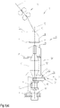
- FIG. 1 shows a schematic representation of a spinning position 10 of a ring spinning machine 1 in a side view, under (a) with an encapsulation in a closed position and under (b) with an encapsulation in an open position.
- a yarn 12 is spun from a roving 11 and placed on a rotating bobbin 13, respectively. wound a spinning cop.
- the coil body 13 is mounted on a spindle 20 that can be driven in rotation.
- the roving 11 runs through a drafting system 7, is then twisted into a yarn 12 and wound onto the bobbin 13.
- the yarn 12 is guided by a ring traveler 31 rotating on a spinning ring 30.
- a thread guide 40 is arranged.
- the radial expansion of a thread balloon 14 that forms during winding can be restricted by a balloon limiter 41, respectively. a balloon constriction ring.
- the balloon limiter 41 is then arranged between the spinning ring 30 and the thread guide 40 .
- the ring spinning machine 1 typically has a large number of spinning stations 10 arranged next to one another.
- the spinning rings 30 of the spinning positions 10 are arranged on a ring rail 3 extending in the longitudinal direction of the ring spinning machine 1 .
- the balloon limiters 41 of the spinning positions 10 arranged next to one another are arranged adjustably on a cross member 4 extending in the longitudinal direction of the ring spinning machine 1 .
- the yarn guides 40 of the spinning stations 10 arranged next to one another are arranged adjustably on a cross member 5 extending in the longitudinal direction of the ring spinning machine 1 .
- the spindles 20 of the spinning positions 10 are arranged on a spindle rail 2 extending in the longitudinal direction of the ring spinning machine 1 .
- the spindle 20 of the spinning position 10 shown in the embodiment comprises a whorl 21 and a spindle bearing 22 at a lower end, with which the spindle 20 is rotatably mounted on the spindle rail 2 .
- the spindle 20 is driven by a tangential belt 6, which can drive several spinning positions and is pressed against the whorl 21 of the spindle 20. Other drives are also possible.
- FIG. 1(a) also shows an encapsulation 50 of the spinning station device 10 in a closed position.
- the encapsulation 50 is formed from two capsule walls divided in the axial direction in the form of partial or partial shells.
- a rear capsule wall 51 is connected to the spindle rail 2 and is fixed relative to the spindle or fixed but removably mounted.
- a front, operator-side enclosure wall 52 is openable, e.g., by pivoting about a hinge 54 having an axis lying in a plane perpendicular to the axis of the spindle or enclosure.
- the hinge 54 is located on two lateral legs 53 of the rear capsule wall 51, which protrude over the front capsule wall 52 to the front.
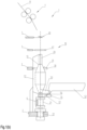
- a spindle brake 60 is shown schematically in the illustrated embodiment, which is arranged here directly below the spool body 13 and above the whorl 21 of the spindle 20 .
- the front capsule wall 52 has a brake actuation device 55 for activating and controlling the spindle brake 60 .
- This is implemented here in the form of an actuating arm 56 with a ball 57 formed on its free end.
- the front capsule wall 52 has a defined end position in the closed state.
- Means for moving the thread traversing in the axial direction of the spindle 20 or the bobbin 13, e.g. in the form of a spinning ring 30 and a ring traveler 31, are provided.
- This can be a slot with a ring holder, for example, in the rear capsule wall 51 or, for example, a magnetic guide for the spinning ring 30 .
- Fig.1(b) shows the spinning position device 1(a) with the enclosure 50 in an open position.
- the front capsule wall 52 is pivoted forwards and downwards about the hinge 54, so that the front capsule wall 52 is essentially in a horizontal position.
- the bobbin 13 is freely accessible for operation.
- the front capsule wall 52 can be moved from the closed position to the open position easily by hand (or by means of a robot).
- the brake actuation device 55 is attached to the lower end of the front capsule wall 52 .
- Other configurations of the brake actuation device are also possible.
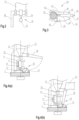
- FIG. 2 shows a front view of the front capsule wall 52 with the brake actuation device 55 designed as an actuation arm 56 and ball 57.
- the spindle brake 60 is designed as a clamp or pliers and has a first brake lever 61 and a second brake lever 62 .
- the two brake levers 61, 62 are connected to one another via a hinge 63.
- the two brake levers 61, 62 each have a brake or clamping jaw, which is placed around the spindle 20 of the spinning station device 10.
- the spindle brake 60 is actuated, the clamping jaws are pressed against the spindle 20 and brake it.
- the respective other end of the two brake levers 61, 62 is designed in such a way that the brake actuation device 55 can be inserted between the two brake levers 61, 62 and presses these ends of the brake levers 61, 62 apart.
- the clamping jaws are pressed together and brake the spindle.
- the spindle brake 60 can thus be actuated with a suitable brake actuation device 55, for example in the form of a wedge, a ball 57, a cylinder or another suitable form, and its braking force can be continuously controlled or regulated.
- a suitable brake actuation device 55 for example in the form of a wedge, a ball 57, a cylinder or another suitable form, and its braking force can be continuously controlled or regulated.
- the gap shown between the brake levers 61, 62 is wedge-shaped and straight, with the wedge shape being able to have a different angle or any desired wedge-shaped curved contour in order to be able to adjust the braking effect depending on the path or pivoting angle of the actuation.
- One of the brake levers--here the second brake lever 62-- is resilient in that it has, for example, two parts connected via a spring element 64.
- the spring element 64 can be spring steel.
- the two brake levers 61, 62 each have stop surfaces 65 for the ball 57 of the brake actuation device 55 on the end facing away from the spindle, which approach the hinge 63 so that between the Brake levers 61, 62 is formed a tapering gap into which the ball 57 is inserted.
- the ends of the spindle brake 60 facing away from the spindle are pushed apart and the clamping jaws are pressed against the spindle 20 . The braking effect increases.
- the brake levers can have stop faces 66 for a constant braking effect, which run essentially parallel to one another when the brake actuation device 55 is inserted.
- the encapsulation 50 can be brought into the fully open position after it has already generated the maximum braking effect in a partially open position. The braking effect is kept constant.
- the brake actuation device 55 is guided up to a specific insertion depth on the stop surfaces 65 for an increasing braking effect. It is then guided to the stop surfaces 66 for a braking effect that is kept constant until the encapsulation is completely opened.
- the spindle brake can be easily regulated by pivoting the front capsule wall 52 in or out. This is particularly advantageous if a spindle decoupling device 70 is also used, as described below 4 is described.
- a latching position is provided which allows the spindle brake 60 to be kept closed without the brake actuating device 55 having to be held.
- This can be formed in the middle of the gap or at its end. A large number of embodiments are also conceivable for this.
- the brake is designed as a "pliers" that closes when the two actuating levers are pushed apart and does not touch the spindle during normal operation.
- a spring is provided for this purpose, which brings the brake caliper into this position and holds it, and this can also be achieved by a number of other embodiments of the caliper.
- an elastomer or the design of the pliers as a plastic part that is at least partially elastic can assume the same function.
- the spindle brake can also be designed in such a way that it closes when the brake levers are pressed together.
- the brake levers must then be pressed together by a suitable counterpart of the brake actuation device.
- the wedge shape of the gap of the brake levers can also be integrated into the brake actuator.
- one of the brake levers or just one brake shoe can be fixed and only one brake lever is actuated.
- FIG. 4 12 shows a schematic representation of a spindle decoupling device 70 at (a) in a coupled position and at (b) in a decoupled position.
- the front capsule wall 52 has a firmly connected actuating arm 58 for the spindle decoupling device 70.
- In 2 is the actuating arm 58 for the Spindle decoupling device 70 shown in dashed lines. This is offset relative to the spindle 20 in the horizontal longitudinal direction of the ring spinning machine, so that it can actuate the spindle decoupling device 70 arranged next to the spindle 20 .
- the spindle decoupling device 70 has a carriage 72 linearly guided on the spindle rail 2 .
- a decoupling roller 71 with a vertical axis of rotation is mounted on the carriage 72 (the axis of rotation is parallel to the spindle axis).
- the carriage 72 is connected to the spindle rail 2 or a guide plate for the carriage 72 via a toggle lever 73 . Actuation of the toggle lever 73 leads to a linear displacement of the carriage 72 with the decoupling roller 71.
- the spindle decoupling device 70 is arranged in such a way that the decoupling roller 71 lifts the drive belt 6 off the spindle 20 (or the whorl 21 of the spindle 20) when the toggle lever 73 is actuated (cf. Fig.4(b) ) in order not to let the spindle 20 get hot when braked. This is particularly advantageous at higher spindle speeds and greater power transmission.
- the front capsule wall 52 has an actuating arm or actuating lever 58 which is connected in a rotationally fixed manner.
- the drive belt 6 returns the decoupling roller 71, the carriage 72 and the toggle lever 73 to the original position.
- the process can be supported by a suitable mechanism, e.g. by a spring or the like, and the movements can be restricted in such a way that the end positions are defined, but the carriage 72 can be removed.
Landscapes
- Engineering & Computer Science (AREA)
- Mechanical Engineering (AREA)
- Textile Engineering (AREA)
- Spinning Or Twisting Of Yarns (AREA)
Abstract
Description
- Die Erfindung betrifft eine Spinnstelleneinrichtung für eine Ringspinnmaschine umfassend eine drehantreibbar auf einer Spindelbank befestigten Spindel für einen Spulenkörper und eine in Längsrichtung der Spindel verlaufende und den Spulenkörper umschliessende Kapselung.
- Maschinen für Spinnverfahren mit geschlossenem Ende und echter Drehung, wie Ringspinnen, Trichterspinnen, Schlingenspinnen, Spinnen mit rotierenden Ringen, Spinnen mit schwebenden Ringen, Spinnen mit Ballonbegrenzungen aller Art (Multiballon, Balloneinengungshülsen stehend und bewegt, Ballonreduktionen wie Spinnkronen, Spinnfinger, Balloneinengungsringe usw.), Topfspinnen, Muranospinnen, sind allgemein bekannt.
- Solche Maschinen besitzen üblicherweise eine Vielzahl von Spinnstellen nebeneinander, die gleichartig oder in zueinander ähnlicher Form bewegt werden. Diese Spinnverfahren können in gleicher Weise zum Zwirnen verwendet werden, wobei hierzu nicht mehr im Einzelnen eingegangen wird. Faden ist der Oberbegriff für Garn, Filament und Zwirn. Im Folgenden wird in der Regel von «Garn» und «Spinnen» gesprochen. Dem Fachmann ist jedoch bekannt, dass die Begriffe auch für «Faden» und «Zwirnen» gelten können.
- Bereits heute werden viele schnelllaufende Ringspinnmaschinen über der kostenoptimalen Geschwindigkeit, die sich aus ihrer Produktion pro Spindelstunde und dem Energieverbrauch ergibt, betrieben. Die Kosten reduzieren sich mit der Erhöhung der Produktion linear, der Energieverbrauch erhöht sich exponentiell mit einem Exponenten von etwa 2 bis 4, in der Regel etwa mit einem Exponenten von 3.2 bis 3.4.
- Der Grund für die exponentielle Steigerung des Energieverbrauchs ist, dass bei Spinnverfahren mit geschlossenem Ende und einfacher echter Drehung die Auflaufspulen auf der Maschine zwingend gedreht werden müssen (Andernfalls müsste die Maschine um die Spule gedreht werden.). Der Spulenkörper, in der Regel in Form eines Kopses wirkt dann als Ventilator.
- Zum Zweck des Energiesparens durch Reduktion der zu beschleunigenden Luftmasse sind Kapselungen bekannt. Dabei wird der Kops und/oder der Fadenballon in der Regel durch eine zylindrische Hülse gekapselt, deren Durchmesser um einige Millimeter grösser als der Kops bzw. der Ballon ist. Das funktioniert, behindert jedoch die Zugänglichkeit zum Kops in verschiedenen Betriebssituationen, wie z.B. beim Fadenbruchbeheben oder beim Anspinnen.
- Eine besondere Form der Ballonkapselung ist die Balloneinengungshülse, wie diese z.B. in
DE1510657B1 oderDE19848752A1 beschrieben ist. - Die Spule bzw. der Kops dreht sich auf der Achse einer Spindel und ist mit dieser z.B. durch Reibschluss verbunden. Die Spindel kann durch einen Bandantrieb oder einzelmotorisch getrieben sein. Es existiert eine grosse Zahl von Lagerungsvarianten, die idealerweise von der Kapselung unabhängig sein sollten. Die Spindeln sind in der Regel in einer Spindelbank befestigt. Diese kann fest oder in axialer Richtung der Spindel beweglich gestaltet sein.
- Weiterhin muss eine Relativbewegung in axialer Richtung der Spule (bzw. der Spindel) zwischen dieser und einem Organ zur Definition der Fadenverlegung realisiert werden, damit nicht alles Garn an der gleichen Stelle als Wulst aufgewunden wird, sondern in einer durch die Relativbewegung bestimmbaren Spulenaufbauform (z.B. als Kopswindung).
- Organe zur Fadenverlegung sind z.B. Ring und Läufer, der Glocken- oder Trichterrand beim Glocken-, Trichter- oder Schlingenspinnen oder ein Fadenführer beim Trichter- oder Muranospinnen, Fadenführerrohre oder Ähnliches.
- Die Elemente zur Fadenverlegung sind in der Regel nebeneinander an einem langen Element befestigt, das je nach Element z.B. Ring-, Trichter, Glocken- oder Fadenführerbank oder -rahmen genannt wird.
- Die Relativbewegung kann durch die Bewegung einer oder beider Elemente zueinander realisiert werden. Auf weitverbreiteten konventionellen Ringspinnmaschinen wird die Ringbank bewegt und die Spindelbank steht fest am Maschinengestell.
- Wird nun eine Spindel gekapselt, so muss entweder die Relativbewegung der Fadenverlegung im gekapselten Bereich ermöglicht werden, oder auf einen grossen Teil der Kapselung und damit der Energieeinsparung verzichtet werden.
- Kapselungen können an der Ringbank angebracht werden, wie das in
CH683349A5 DE1510657B1 oderDE19848752A1 ) beschrieben ist, wobei hier nur ein bestimmter, kleiner Teil des Spinnbereichs gekapselt ist. Die Energieeinsparung ist dabei gering. -
CN209957949U zeigt eine unvollständige Kapselung, die unterhalb der Ringbank angebracht wird, aber eine nach oben verschobene, verlängerte Befestigung der Spindel mit einem einzelmotorischen Antrieb zeigt. Die Kapselung ist nicht vollständig und die Spindel relativ labil, wobei der Luftspalt des Aussenläufers durch die Präzession der Spindel nicht konstant gehalten werden kann. -
CH706759A1 -
DE1685679A1 zeigt zwei verschiedene verkürzbare Kapselungsvarianten, die jedoch weder auf der ganzen Länge den energetisch optimalen Durchmesser besitzen noch stabil, schmutzresistent und leicht zu reinigen sind. Zudem bieten sie keine leichte Zugänglichkeit. -
EP3483313A1 beschreibt eine bewegte Spindelbank, wobei die Spindel in die Kapselung einfährt. Auch hier ist eine aufwendige, lange Spindelform nötig. -
WO2020105006A1 beschreibt eine lange magnetisch gelagerte Spindel, die geeignet ist, in eine Kapselung, die an einer Ringbank angebracht ist, einzufahren. Der Aufwand, der für den Einsatz der Kapselung betrieben werden muss, ist erheblich. -
CH715908A1 -
JP2013170337A -
CN210194054U löst das Problem der Integration der Fadenführung und führt den Spinnring durch Magneten von aussen gehalten innerhalb der Kapselung, ohne einen Schlitz zu benötigen. Der Fadenführer ist in den Deckel integriert und die Bauhöhe ist optimiert. Die Kapselung rotiert und würde zur Energieeinsparung ihrerseits eine Kapselung benötigen. Der technische Aufwand ist hoch. Die Spinnstelle ist sehr schlecht zugänglich. - Beim Anspinnen auf einer konventionellen Ringspinnmaschine wird ein bereits auf der Spule befindliches oder dort zum Zweck des Anspinnens aufgebrachtes Fadenstück nach oben durch das oder die Fadenführungsorgane eingefädelt, die Spindel wird gestartet und das Fadenende wird mit den aus dem Streckwerk auslaufenden Fasern zusammengebracht, so dass sich die neuen Fasern mit dem alten Garnstück verdrehen und somit verbinden. Dies kann z.B. durch Andrehen am Streckwerksausgang oder durch hinterlegen an der Auslaufwalze geschehen. Danach beginnt der normale Spinnvorgang, bei dem die gelieferten Fasern eine bestimmte Anzahl von Drehungen pro Länge des Garns erhalten.
- Die Spindel muss jedoch zwangsläufig mit einem fertig gedrehten Faden gestartet werden. Während der Zeit des noch verbleibenden Anspinnvorgangs erhält der Faden zusätzliche Drehungen in immer das gleiche Garnstück, was bei zu langsamem Anspinnen oder zu schneller Spinngeschwindigkeit dazu führen kann, dass der Faden überdreht wird und dadurch bricht.
- Eine Aufgabe der vorliegenden Erfindung ist es, eine vollständige Kapselung einer Spindel resp. eines Spulenkörpers zu ermöglichen, welche eine einfache, mit der Bauweise einer üblichen Ringspinnmaschine vereinbare Zugänglichkeit zur Spindel erlaubt. Eine weitere Aufgabe besteht darin, die Zugänglichkeit mit einer einfachen Bedienung einer einzelnen Spinnstelle, insbesondere bei einem Fadenbruch, zu ermöglichen. Insbesondere soll es möglich sein, eine Fadenbruch in den heute üblichen 6 bis 10 Sekunden zu beheben.
- Diese Aufgabe wird durch eine Spinnstelleneinrichtung mit den Merkmalen des Anspruch 1 gelöst. Die Spinnstelleneinrichtung für eine Ringspinnmaschine umfasst eine drehantreibbar auf einer Spindelbank befestigten Spindel für einen Spulenkörper (d.h. eine nackte Hülse oder eine Spule mit aufgewickeltem Garn) und eine in Längsrichtung der Spindel verlaufende und den Spulenkörper umschliessende Kapselung, wobei die Kapselung mit der Spindelbank verbunden ist. Die Kapselung ist in Längsrichtung geteilt und weist eine hintere Kapselwand und eine vordere, bedienerseitige Kapselwand auf. Die vordere Kapselwand ist in eine offene Stellung bewegbar, so dass in der offenen Stellung der Spulenkörper der Spinnstelleneinrichtung für eine Bedienung zugänglich ist.
- In einigen Ausführungsformen kann die vordere Kapselwand an einem unteren Bereich schwenkbar verbunden und in eine vorzugsweise horizontale Lage schwenkbar ist. Alternativ kann die vordere Kapselwand durch eine lineare Bewegung, durch Schwenken um die Spindelachse oder durch eine Schiebebewegung oder dergleichen in eine offene Stellung gebracht werden.
- Die Erfindung hat den Vorteil, dass die Kapselung sehr einfach geöffnet werden kann. Bei einer Ringspinnmaschine verlaufen die Drehachsen der Spindeln in den einzelnen Spinnstellen vertikal. Die Spindeln sind am unteren Ende drehantreibbar auf einer Spindelbank gelagert. Indem die vordere, bedienerseitige Kapselwand am unteren Ende drehbar gelagert ist, kann sie beim Ausschwenken von einer vertikalen, geschlossenen Stellung in eine horizontale, offene Stellung die Zugänglichkeit des Spulenkörpers von vorn, d.h. von der Bedienseite der Ringspinnmaschine, zuverlässig gewährleisten, so dass ein maschinelles Anspinnen oder eine automatische oder händische Bedienung bei einem Fadenbruch auf problemloser Weise ermöglicht ist. Eine solche Kapselung eignet sich auch für eine Nachrüstung von bestehenden Spinnmaschinen.
- In einigen Ausführungsformen kann die hintere Kapselwand fest mit der Spindelbank verbunden sein und die vordere Kapselwand kann schwenkbar mit der hinteren Kapselwand verbunden sein. Dazu kann die hintere Kapselwand beispielsweise zwei seitlich angeordnete und nach vorne ragende Schenkel aufweisen, an denen die vordere Kapselwand z.B. mittels einer Achse schwenkbar gehalten ist. Alternativ kann die vordere Kapselwand auch schwenkbar mit der Spindelbank verbunden sein, resp. mit einer an der Spindelbank befestigten Halterung.
- In einigen Ausführungsformen kann die hintere Kapselwand und die vordere Kapselwand je als Teilschale ausgebildet sein, die vorzugsweise im Bereich der Spindelbank mit einem Scharnier miteinander verbunden sind. Zusammen umschliessen die Teilschalen 360° der Spindelachse. Die Teilschalen können als zwei Halbschalen ausgebildet sein, welche jeweils 180° umschliessen. Andere Aufteilungen sind ebenfalls denkbar.
- In einigen Ausführungsformen kann die Spinnstelleneinrichtung weiter eine Spindelbremse aufweisen, welche durch Öffnen der Kapselung betätigbar ist, um die Spindel resp. den Spulenkörper abzubremsen. Eine solche mechanische Spindelbremse ist oft notwendig, weil die Spulenkörper aufgrund der hohen Drehzahl nicht mehr von Hand abgebremst werden können. Eine zuverlässige schnelle Abbremsung ist auch notwendig, um z.B. eine Fadenbruch in möglichst kurzer Zeit zu beheben.
- Spindelbremsen sind an sich bekannt und sind üblicherweise derart ausgelegt, dass sie vom Bedienpersonal mit dem Knie betätigt werden, so dass die beiden Hände für die Behebung des Fadenbruchs frei sind.
- In einigen Ausführungsformen kann nun die vordere Kapselwand eine Bremsbetätigungseinrichtung aufweisen, welche die Spindelbremse durch Bewegen der vorderen Kapselwand in die offene Stellung betätigt. Dies hat den Vorteil, dass zeitgleich mit dem Öffnen der Kapselung die Spindel resp. der Spulenkörper abgebremst wird. Auf eine umständliche Bremsung mit Hilfe des Knies kann verzichtet werden. Sobald der Kapselung vollständig geöffnet ist, ist auch der Spulenkörper abgebremst und das Garnende kann wieder korrekt eingefädelt und mit der Lunte verbunden werden. Bei Schliessen der Kapselung wird entsprechend die Spindelbremse gelöst und der Spinnvorgang wird fortgesetzt.
- In einigen Ausführungsformen kann die Spindelbremse in ihrer Bremskraft steuerbar, vorzugsweise stufenlos steuerbar, sein. Mit einer steuerbaren Bremskraft kann die Spindel je nach Bedarf schnell oder langsam bis zum Stillstand gebremst werden. Umgekehrt kann das Anlaufen der Spindel durch Schliessen der Kapselung resp. der vorderen Kapselwand reguliert werden, so dass die Spindel die für das Anspinnen benötigte Drehzahl aufweist.
- In einigen Ausführungsformen kann eine Bremswirkung der Spindelbremse mit zunehmendem Öffnungsgrad der Kapselung bis zu einer maximalen Bremswirkung zunehmen. Durch Öffnen oder Ausschwenken der vorderen Kapselwand kann die Spindelbremse über die an der vorderen Kapselwand befestigten Bremsbetätigungseinrichtung betätigt werden. Dabei kann die Spindelbremse und die Bremsbetätigungseinrichtung derart ausgestaltet sein, dass mit zunehmenden Öffnungsgrad der Kapselung die Bremswirkung zunimmt. Während dem Öffnen wird die Spindel resp. der Spulenkörper abgebremst. Umgekehrt nimmt beim Schliessen der Kapselung die Bremswirkung ab und die Spindel resp. der Spulenkörper beginnt wieder zu drehen. Die vordere Kapselwand wirkt dabei wie ein Bremshebel zur Regulation der Drehzahl der Spindel. Auf diese Weise kann insbesondere beim Schliessen der Kapselung ein Anlaufen der Spindel reguliert werden, so dass die optimale Drehzahl für das Eindrehen des Garns am Ende der Fadenbruchbehebung erreicht wird. Sobald die Kapselung vollständig geschlossen ist, läuft die Spindel wieder mit der Betriebsdrehzahl und der Spinnvorgang wird fortgesetzt.
- In einigen Ausführungsformen kann die Spindelbremse zwischen dem Spulenkörper und dem Wirtel oder zwischen dem Wirtel und der Spulenlagerung angeordnet sein.
- In einigen Ausführungsformen kann die Spindelbremse in Form einer Klemme oder Zange ausgebildet sein. Die Klemme kann einen ersten Bremshebel und einen zweiten Bremshebel aufweisen, welche über ein Scharnier miteinander verbunden sind. Einer der Bremshebel kann zudem federnd ausgebildet sein. Jeweils an einem Ende der beiden Bremshebel kann eine Klemmbacke zum Abbremsen der Spindel ausgebildet sein, welche dazu um die Spindel gelegt sind. Das jeweilige andere Ende der beiden Bremshebel können so ausgebildet sein, dass die Bremsbetätigungseinrichtung zwischen die beiden Bremshebel einführbar ist und diese Enden der Bremshebel auseinanderdrücken. Dabei werden die Klemmbacken zusammengedrückt und bremsen die Spindel.
- Bei einer Spindelbremse in Form einer Klemme oder Zange können die beiden Bremshebel an dem Ende, in welche die Bremsbetätigungseinrichtung eingeführt wird (d.h. das spindelabgewandte Ende), schräge Anschlagsfläche aufweisen, welche sich zum Scharnier hin annähern. Auf diese Weise kann die Bremswirkung mit zunehmender Öffnung der Kapselung resp. zunehmender Einführung der Bremsbetätigungseinrichtung zwischen die Bremshebel zunehmen. Ab einer vorbestimmten Einführungstiefe können die beiden Anschlagsflächen zueinander parallel verlaufen, so dass bei einer noch weiteren Einführung der Bremsbetätigungseinrichtung die Bremswirkung nicht mehr zunimmt, aber gehalten bleibt. Dies ist insbesondere von Vorteil, wenn zusätzlich eine nachfolgend beschriebene Spindelentkoppelungseinrichtung eingesetzt wird.
- Andere Ausgestaltungen der Spindelbremse mit z.B. einer Bremsbacke und einer Kulissenführung für eine Bremsbetätigungseinrichtung der Kapselung sind auch möglich. Die Kulissenführung kann dabei derart ausgestaltet sein, dass die Bremswirkung in Abhängigkeit des Öffnungsgrad der Kapselung zunimmt und gegebenenfalls ab einen bestimmten Öffnungsgrad konstant gehalten wird.
- Spinnstelleinrichtungen können mit Einzelspindelantriebseinheiten versehen sein, oder eine Antriebseinheit kann beispielsweise über einen Antriebsriemen mehrere Spinnstelleinrichtungen antreiben.
- In einigen Ausführungsformen kann die Spinnstelleneinrichtung eine Einzelspindelantriebseinheit aufweisen, die durch Öffnen oder Schliessen der Kapselung (ähnlich wie die die beschriebene Spindelbremse) steuerbar ist. Dazu kann die Spinnstelleneinrichtung mit einer Antriebssteuereinheit versehen sein, die durch Öffnen und Schliessen der Kapselung betätigbar ist. Durch Öffnen der Kapselung kann die Drehzahl der Antriebseinrichtung reduziert oder die Antriebseinrichtung kann gänzlich ausgeschaltet werden. Umgekehrt kann durch Schliessen der Kapselung die Drehzahl der Antriebseinrichtung erhöht oder die Antriebseinrichtung wieder eingeschaltet werden. Die Steuerung kann mechanisch und/oder elektronisch ausgebildet sein.
- In einigen Ausführungsformen kann die Spinnstelleneinrichtung eine Spindelentkoppelungseinrichtung aufweisen, welche durch Öffnen der Kapselung, bevorzugt beim Ausschwenken der vorderen Kapselwand in die offene Stellung, ein Antriebselement der Ringspinnmaschine von der Spindel entkoppelt. Das Antriebselement kann ein Antriebsriemen sein, welcher zum Betreiben der Spindel an einen Wirtel der Spindel anliegt. Ein solche Spindelentkoppelungseinrichtung ist von Vorteil, um eine Überhitzung der gebremsten Spindel durch z.B. einen weiterlaufenden Antriebsriemen zu vermeiden.
- In einigen Ausführungsformen kann die Spindelentkoppelungseinrichtung eine Entkoppelungsrolle aufweisen, welche in Richtung des Antriebsriemens bewegbar gelagert sein kann, so dass die Entkoppelungsrolle bei Betätigung der Spindelentkoppelungsreinrichtung den Antriebsriemen von dem Wirtel wegdrückt. Bei Öffnen der Kapselung wird entsprechend der Antriebsriemen von der Spindel entkoppelt und die Spindel kann einfacher abgebremst werden.
- Die Entkoppelung oder das Ausschalten einer Antriebseinheit ist insbesondere von Vorteil, wenn die Spinnstelle aufgrund eines Defekts längere Zeit stillstehen muss.
- In einigen Ausführungsformen können die Spindelbremse und die Spindelentkoppelungseinrichtung resp. die Antriebssteuereinheit miteinander kombiniert sein. Bevorzugt kann die Spindelbremse und die Spindelentkoppelungseinrichtung resp. die Antriebssteuereinheit derart ausgestaltet sein, dass durch Öffnen der Kapselung, vorzugsweise beim Ausschwenken der vorderen Kapselwand in die offene Stellung, zuerst die Spindelbremse bis zur maximalen Bremswirkung betätigt ist und anschliessend erst das Antriebselement der Ringspinnmaschine von der Spindel entkoppelt ist. Umgekehrt kann die Spindelbremse und die Spindelentkoppelungseinrichtung resp. die Antriebssteuereinheit derart ausgestaltet sein, dass durch Schliessen der Kapselung zuerst das Antriebselement der Ringspinnmaschine mit der Spindel gekoppelt ist bevor anschliessend die Spindelbremse gelöst wird.
- In einigen Ausführungsformen kann die vordere Kapselwand zur Betätigung der Spindelentkopplungseinrichtung resp. der Antriebssteuereinheit einen Betätigungsarm aufweisen. Die Entkopplungsrolle kann beispielsweise auf einem horizontal geführten Schlitten befestigt sein, wobei der Schlitten mittels eines Kniehebels betätigbar ist. Der Betätigungsarm kann beim Ausschwenken der vorderen Kapselwand auf den Kniehebel einwirken und so das Antriebselement entkoppeln. Der Betätigungsarm kann dabei derart ausgestaltet sein, dass er erst bei einer fast vollständigen Öffnung der Kapselung auf die Spindelentkopplungseinrichtung einwirkt, so dass die Spindel erst nach deren Abbremsen entkoppelt wird. Dies ist insbesondere von Vorteil, damit beim Schliessen der Kapselung zuerst die Spindel mit dem Antriebselement gekoppelt wird, bevor die Bremswirkung aufgehoben wird, um eine zuverlässige Regulierung der Bremswirkung resp. ein graduelles Aufheben der Bremswirkung beim Schliessen zu erlauben.
- Die Kombination der Kapselung mit der in Abhängigkeit des Öffnungsgrads der Kapselung regulierbaren Spindelbremse kann auch als eigenständige Erfindung betrachtet werden. Ebenso kann die graduelle Regulierung der Spindelbremse selbst als eigenständige Erfindung betrachtet werden. Auch die Spindelentkopplungseinrichtung alleine oder in Kombination mit der Kapselung mit oder ohne Spindelbremse kann als eigenständige Erfindung betrachtet werden.
- Ebenso ist eine weitere Form der Erfindung denkbar, bei der eine mechanische Bremse (schnelle, kräftige Bremswirkung) oder eine Ansteuerung des Antriebs auf eine einzelmotorisch getriebene Spindel wirkt.
- Allen Ausführungen gemeinsam ist jedoch das Bremsen der Spindel durch die Öffnung der Kapselung der Spinnstelle und die steuerbare Geschwindigkeit der Spindel zumindest beim Hochlaufen bestimmt durch den Öffnungszustand der Kapselung.
- Die Erfindung betrifft weiter eine Ringspinnmaschine mit einer Vielzahl der voran beschriebenen Spinnstelleneinrichtungen.
- Die Erfindung soll nachfolgend anhand von Ausführungsbeispielen im Zusammenhang mit der(n) Zeichnung(en) näher erläutert werden. Es zeigen:
- Fig. 1(a)
- eine Seitenansicht einer Spinnstelleneinrichtung mit einer Kapselung unter (a) in einer geschlossenen Stellung und unter (b) in einer offenen Stellung;
- Fig. 2
- eine Vorderansicht auf die vordere Kapselwand mit einer Bremsbetätigungseinrichtung;
- Fig. 3
- eine Spindelbremse;
- Fig. 4(a)
- eine Spindelentkopplungseinrichtung unter (a) in einer gekoppelten Stellung und unter (b) in einer entkoppelten Stellung;
- In den Figuren sind für dieselben Elemente jeweils dieselben Bezugszeichen verwendet worden und erstmalige Erklärungen betreffen alle Figuren, wenn nicht ausdrücklich anders erwähnt.
-
Fig. 1 zeigt eine schematische Darstellung einer Spinnstelle 10 einer Ringspinnmaschine 1 in einer Seitenansicht, unter (a) mit einer Kapselung in einer geschlossen Stellung und unter (b) mit einer Kapselung in einer offenen Stellung. - An der Spinnstelle 10 wird aus einer Lunte 11 ein Garn 12 gesponnen und auf einen sich drehenden Spulenkörper 13 resp. einen Spinnkops gewickelt. Der Spulenkörper 13 ist dazu auf einer drehantreibbaren Spindel 20 montiert. Während dem Spinnvorgang durchläuft die Lunte 11 ein Streckwerk 7, wird anschliessend zu einem Garn 12 verdreht und auf den Spulenkörper 13 gewickelt. Zur Ablage des Garns 12 auf den Spulenkörper 13 erfolgt eine Führung des Garns 12 durch einen auf einem Spinnring 30 rotierenden Ringläufer 31. Zur Führung des Garns 12 ist weiter oberhalb der Spindel 20 resp. des Spulenkörpers 13 ein Fadenführer 40 angeordnet. Die radiale Ausdehnung eines sich beim Aufwinden ausbildende Fadenballons 14 kann durch eine Ballonbegrenzer 41 resp. einen Balloneinengungsring begrenzt werden. Der Ballonbegrenzer 41 ist dann zwischen dem Spinnring 30 und dem Fadenführer 40 angeordnet. Die Ringspinnmaschine 1 weist typischerweise eine Vielzahl nebeneinander angeordneter Spinnstellen 10 auf.
- Die Spinnringe 30 der Spinnstellen 10 sind an einer sich in Längsrichtung der Ringspinnmaschine 1 erstreckenden Ringbank 3 angeordnet. Die Ballonbegrenzer 41 der nebeneinander angeordneten Spinnstellen 10 sind an einer sich in Längsrichtung der Ringspinnmaschine 1 erstreckenden Traverse 4 justierbar angeordnet. Entsprechend sind die Fadenführer 40 der nebeneinander angeordneten Spinnstellen 10 an einer sich in Längsrichtung der Ringspinnmaschine 1 erstreckenden Traverse 5 justierbar angeordnet.
- Die Spindeln 20 der Spinnstellen 10 sind an einer sich in Längsrichtung der Ringspinnmaschine 1 erstreckenden Spindelbank 2 angeordnet. Die in der Ausführungsform dargestellte Spindel 20 der Spinnstelle 10 umfasst an einem unteren Ende einen Wirtel 21 und ein Spindellager 22, mit welchem die Spindel 20 auf der Spindelbank 2 drehbar gelagert sind. Die Spindel 20 wird über einen Tangentialriemen 6 angetrieben, welcher jeweils mehrere Spinnstellen antreiben kann und gegen den Wirtel 21 der Spindel 20 gedrückt wird. Andere Antriebe sind auch möglich.
-
Fig. 1(a) zeigt weiter eine Kapselung 50 der Spinnstelleneinrichtung 10 in einer geschlossenen Stellung. - Die Kapselung 50 ist aus zwei in axialer Richtung geteilten Kapselwände in Form von Teil- oder Teilschalen ausgebildet. Eine hintere Kapselwand 51 ist mit der Spindelbank 2 verbunden und relativ zur Spindel fix angebracht oder fix, aber entfernbar angebracht. Eine vordere, bedienerseitige Kapselwand 52 lässt sich öffnen, z.B. durch Schwenken um ein Scharnier 54 mit einer Achse die in einer Ebene senkrecht zur Spindel- bzw. Kapselungsachse liegt. In der gezeigten Ausführungsform befindet sich das Scharnier 54 an zwei seitlichen Schenkeln 53 der hinteren Kapselwand 51, welche über die vordere Kapselwand 52 nach vorne ragen.
- Weiter ist in der dargestellten Ausführungsform schematisch eine Spindelbremse 60 gezeigt, welche hier direkt unterhalb des Spulenkörpers 13 und über dem Wirtel 21 der Spindel 20 angeordnet ist.
- Zur Aktivierung und Steuerung der Spindelbremse 60 weist die vordere Kapselwand 52 eine Bremsbetätigungseinrichtung 55 auf. Diese ist hier in Form eines Betätigungsarms 56 mit einer an dessen freien Ende ausgebildeten Kugel 57 realisiert.
- Die vordere Kapselwand 52 besitzt eine definierte Endposition im geschlossenen Zustand. Mittel zur Bewegung der Fadenverlegung in axialer Richtung der Spindel 20 bzw. des Spulenkörpers 13, z.B. in Form eines Spinnrings 30 und eines Ringläufers 31, sind vorgesehen. Dies kann ein Schlitz mit einem Ringhalter beispielsweisen in der hinteren Kapselwand 51 oder beispielsweise auch eine magnetische Führung des Spinnrings 30 sein.
-
Fig. 1(b) zeigt die Spinnstelleneinrichtung ausFig. 1(a) mit der Kapselung 50 in einer offenen Stellung. Dabei ist die vordere Kapselwand 52 um das Scharnier 54 nach vorne unten geschwenkt, so dass die vordere Kapselwand 52 im Wesentlichen in einer horizontalen Lage ist. Auf diese Weise ist der Spulenkörper 13 für eine Bedienung frei zugänglich. Die vordere Kapselwand 52 kann einfach von Hand (oder mittels eines Robotors) von der geschlossenen Stellung in die offene Stellung bewegt werden. - Am unteren Ende der vorderen Kapselwand 52 ist die Bremsbetätigungseinrichtung 55 angebracht. Beim Ausschwenken der vorderen Kapselwand 52 wird die Bremsbetätigungseinrichtung 55 - in der gezeigten Ausführungsform die Kugel 57 der Bremsbetätigungseinrichtung 55 - in die Spindelbremse eingeführt und erwirkt dabei die Bremsung der Spindel. Andere Ausgestaltungen der Bremsbetätigungseinrichtung sind auch möglich.
-
Fig. 2 zeigt eine Vorderansicht auf die vordere Kapselwand 52 mit der Bremsbetätigungseinrichtung 55 ausgestaltet als Betätigungsarm 56 und Kugel 57. -
Fig. 3 zeigt eine Ansicht auf eine Spindelbremse 60 von oben. In der gezeigten Ausführungsform ist die Spindelbremse 60 als Klemme oder Zange ausgebildet und weist einen ersten Bremshebel 61 und einen zweiten Bremshebel 62 auf. Die beiden Bremshebel 61, 62 sind über eine Scharnier 63 miteinander verbunden. An einem Ende weisen die beiden Bremshebel 61, 62 jeweils eine Brems- oder Klemmbacke auf, welche um die Spindel 20 der Spinnstelleneinrichtung 10 gelegt ist. Bei Betätigung der Spindelbremse 60 werden die Klemmbacken gegen die Spindel 20 gedrückt und bremsen diese ab. - Das jeweilige andere Ende der beiden Bremshebel 61, 62 ist so ausgebildet sein, dass die Bremsbetätigungseinrichtung 55 zwischen die beiden Bremshebel 61, 62 einführbar ist und diese Enden der Bremshebel 61, 62 auseinanderdrückt. Dabei werden die Klemmbacken zusammengedrückt und bremsen die Spindel.
- Die Spindelbremse 60 kann also mit einer geeigneten Bremsbetätigungseinrichtung 55, beispielsweise in Form eines Keils, einer Kugel 57, eines Zylinders oder einer anderen geeigneten Form betätigt und in ihrer Bremskraft stufenlos gesteuert oder geregelt werden. Der gezeigte Spalt zwischen den Bremshebeln 61 , 62 ist keilförmig und gerade ausgebildet, wobei die Keilform einen anderen Winkel oder eine beliebige keilförmige Kurvenkontur besitzen kann, um die Bremswirkung abhängig vom Weg oder Schwenkwinkel der Betätigung einstellen zu können.
- Einer der Bremshebel - hier der zweite Bremshebel 62 ist federnd ausgebildet in dem er beispielsweise zwei über ein Federelement 64 verbundene Teile aufweist. Das Federelement 64 kann ein Federstahl sein.
- Beim Ausschwenken der vorderen Kapselwand 52 wird die Kugel 57 der Bremsbetätigungseinrichtung 55 immer tiefer in den Spalt zwischen die beiden Bremshebel 61, 62 eingeführt. Um die Bremswirkung graduell in Abhängigkeit des Öffnungsgrads der Kapselung 50 zu erhöhen, weisen die beiden Bremshebel 61, 62 am spindel-abgewandten Ende jeweils Anschlagsflächen 65 für die Kugel 57 der Bremsbetätigungseinrichtung 55 auf, welche sich zum Scharnier 63 hin annähern, so dass zwischen den Bremshebeln 61, 62 ein sich verjüngender Spalt ausgebildet ist, in den die Kugel 57 eingeführt wird. Mit zunehmender Tiefe der Einführung werden die spindel-abgewandten Enden der Spindelbremse 60 auseinandergedrückt und die Klemmbacken gegen die Spindel 20 gedrückt. Die Bremswirkung nimmt dabei zu.
- Ab einer bestimmten Einführtiefe können die Bremshebel Anschlagflächen 66 für eine konstant gehaltene Bremswirkung aufweisen, welche bei eingeführter Bremsbetätigungseinrichtung 55 im Wesentlichen parallel zueinander verlaufen. Auf diese kann die Kapselung 50 in die vollständig offene Stellung gebracht werden, nachdem sie in einer teiloffenen Stellung bereits die maximale Bremswirkung erzeugt hat. Die Bremswirkung wird dabei konstant gehalten.
- Mit anderen Worten wird demnach durch Öffnen der Kapselung 50 die Bremsbetätigungseinrichtung 55 bis zu einer bestimmten Einführtiefe an den Anschlagsflächen 65 für eine zunehmende Bremswirkung geführt. Danach wird sie bis zur vollständigen Öffnung der Kapselung an den Anschlagsflächen 66 für eine konstant gehaltene Bremswirkung geführt. Auf diese Weise ist die Spindelbremse durch Aus- oder Einschwenken der vorderen Kapselwand 52 einfach zu regulieren. Dies ist insbesondere dann von Vorteil, wenn zusätzlich eine Spindelentkoppelungseinrichtung 70 eingesetzt wird, wie sie nachfolgend unter
Fig. 4 beschrieben ist. - Weiterhin ist eine Rastposition vorgesehen, die es erlaubt, die Spindelbremse 60 geschlossen zu halten, ohne dass die Bremsbetätigungseinrichtung 55 gehalten werden muss. Diese kann mittig im Spalt oder an dessen Ende ausgebildet sein. Auch dafür ist eine Vielzahl von Ausführungsformen denkbar.
- Die Bremse ist hier als «Zange» ausgeführt, die beim Auseinanderdrücken der beiden Betätigungshebel schliesst und im Normalbetrieb der Spindel diese nicht berührt. Hierfür ist eine Feder vorgesehen, die die Bremszange in diese Position bringt und hält, wobei dies auch durch eine Reihe anderer Ausführungsformen der Zange erreicht werden kann. Beispielsweise kann ein Elastomer oder die Ausführung der Zange als mindestens in Teilen elastisches Kunststoffteil die gleiche Funktion übernehmen.
- Alternativ kann die Spindelbremse auch so ausgebildet sein, dass sie beim Zusammendrücken der Bremshebel schliesst. Die Bremshebel müssen dann von einem geeigneten Gegenstück der Bremsbetätigungseinrichtung zusammengedrückt werden. Beispielsweise kann die Keilform des Spalts der Bremshebel ebenso in den Bremsbetätigungseinrichtung integriert sein. Ebenso kann einer der Bremshebel oder auch nur eine Bremsbacke fix sein und es wird nur ein Bremshebel betätigt.
-
Fig. 4 zeigt eine schematische Darstellung einer Spindelentkopplungseinrichtung 70 unter (a) in einer gekoppelten Stellung und unter (b) in einer entkoppelten Stellung. Dabei weist die vordere Kapselwand 52 einen fest verbundenen Betätigungsarm 58 für Spindelentkopplungseinrichtung 70. InFig. 2 ist der Betätigungsarm 58 für die Spindelentkoppelungseinrichtung 70 strich-liniert dargestellt. Dieser ist gegenüber der Spindel 20 in horizontaler Längsrichtung der Ringspinnmaschine versetzt, so dass er die neben der Spindel 20 angeordnete Spindelentkoppelungseinrichtung 70 betätigen kann. - Die Spindelentkoppelungseinrichtung 70 weist in der gezeigten Ausführungsform einen auf der Spindelbank 2 linear geführten Schlitten 72 auf. Auf dem Schlitten 72 ist eine Entkopplungsrolle 71 mit vertikaler Drehachse montiert (die Drehachse ist parallel zur Spindelachse). Der Schlitten 72 ist über einen Kniehebel 73 mit der Spindelbank 2 oder einer Führungsplatte für den Schlitten 72 verbunden. Eine Betätigung des Kniehebels 73 führt zu einer linearen Verschiebung des Schlittens 72 mit der Entkoppelungsrolle 71.
- Die Spindelentkoppelungseinrichtung 70 ist derart angeordnet, dass die Entkopplungsrolle 71 bei Betätigung des Kniehebels 73 den Antriebsriemen 6 von der Spindel 20 (resp. dem Wirtel 21 der Spindel 20) abhebt (vgl.
Fig. 4(b) ), um die Spindel 20 im gebremsten Zustand nicht heiss werden zu lassen. Dies ist besonders bei höheren Spindelgeschwindigkeiten und grösserer Leistungsübertragung von Vorteil. - Zur Betätigung des Kniehebels 72 resp. der Spindelentkoppelungseinrichtung 70 weist die vordere Kapselwand 52 einen drehfest verbundenen Betätigungsarm oder Betätigungshebel 58 auf. Wird der Betätigungsarm 58 vom Kniehebel 73 entfernt, so bringt der Antriebsriemen 6 die Entkopplungsrolle 71, den Schlitten 72 und den Kniehebel 73 in die Ausgangsstellung zurück. Der Vorgang kann durch eine geeignete Mechanik z.B. durch eine Feder oder Ähnliches unterstützt werden und die Bewegungen können so beschränkt werden, dass die Endstellungen definiert sind, der Schlitten 72 aber herausnehmbar ist.
- Ebenso sind andere Betätigungsmechanismen der Entkoppelungsrolle, wie beispielsweise Exzenter oder Teilexzenter denkbar, um die Entkoppelungsrolle auszurücken. Allen Lösungen ist jedoch das Abheben des Antriebsbandes von der Spindel gemeinsam.
-
- 1
- Ringspinnmaschine
- 2
- Spindelbank
- 3
- Ringbank
- 4
- Traverse (Ballonbegrenzer)
- 5
- Traverse (Fadenführer)
- 6
- Antriebselement / Tangentialriemen
- 7
- Streckwerk
- 10
- Spinnstelle / Spinnstelleneinrichtung
- 11
- Lunte
- 12
- Garn
- 13
- Spulenkörper / Spinnkops
- 14
- Fadenballon
- 20
- Spindel
- 21
- Wirtel
- 22
- Spindellager
- 30
- Spinnring
- 31
- Ringläufer
- 40
- Fadenführer
- 41
- Ballonbegrenzer
- 50
- Kapselung
- 51
- hintere Kapselwand
- 52
- vordere Kapselwand
- 53
- Schenkel
- 54
- Scharnier / Drehachse
- 55
- Bremsbetätigungseinrichtung
- 56
- Betätigungsarm
- 57
- Kugel
- 58
- Betätigungsarm für Spindelentkopplungseinrichtung
- 60
- Spindelbremse
- 61
- erster Bremshebel
- 62
- zweiter Bremshebel
- 63
- Scharnier
- 64
- Federelement
- 65
- Anschlagfläche für zunehmende Bremswirkung
- 66
- Anschlagfläche für konstante Bremswirkung
- 70
- Spindelentkoppelungseinrichtung
- 71
- Entkopplungsrolle
- 72
- Schlitten
- 73
- Kniehebel
Claims (18)
- Spinnstelleneinrichtung (10) für eine Ringspinnmaschine (1) umfassend eine drehantreibbar auf einer Spindelbank (2) befestigten Spindel (20) für einen Spulenkörper (13) und eine in Längsrichtung der Spindel (20) verlaufende und den Spulenkörper (13) umschliessende Kapselung (50), wobei die Kapselung (50) mit der Spindelbank (2) verbunden ist, dadurch gekennzeichnet, dass die Kapselung (50) in Längsrichtung geteilt ist und eine hintere Kapselwand (51) und eine vordere Kapselwand (52) aufweist, wobei die vordere Kapselwand (51) in eine offene Stellung bewegbar ist, so dass in der offenen Stellung der Spulenkörper (13) der Spinnstelleneinrichtung (10) für eine Bedienung zugänglich ist.
- Spinnstelleneinrichtung nach Anspruch 1, dadurch gekennzeichnet, dass die vordere Kapselwand an einem unteren Bereich schwenkbar verbunden und in eine vorzugsweise horizontale Lage schwenkbar ist.
- Spinnstelleneinrichtung nach Anspruch 2, dadurch gekennzeichnet, dass die hintere Kapselwand (51) fest mit der Spindelbank (2) verbunden ist und die vordere Kapselwand (52) schwenkbar mit der hinteren Kapselwand (51) verbunden ist.
- Spinnstelleneinrichtung nach einem der vorangehenden Ansprüche, dadurch gekennzeichnet, dass die hintere Kapselwand (51) und die vordere Kapselwand (52) je als Teilschale ausgebildet sind, die vorzugsweise im Bereich der Spindelbank (2) mit einem Scharnier (54) miteinander verbunden sind.
- Spinnstelleneinrichtung nach einem der vorangehenden Ansprüche, dadurch gekennzeichnet, dass die Spinnstelleneinrichtung (10) weiter eine Spindelbremse (60) aufweist, welche durch Öffnen der Kapselung (50) betätigbar ist, um die Spindel (20) resp. den Spulenkörper (13) abzubremsen.
- Spinnstelleneinrichtung nach Anspruch 4, dadurch gekennzeichnet, dass die vordere Kapselwand (52) eine Bremsbetätigungseinrichtung (55) aufweist, welche die Spindelbremse (60) durch Bewegen der vorderen Kapselwand (52) in die offene Stellung betätigt.
- Spinnstelleneinrichtung nach Anspruch 4 oder 5, dadurch gekennzeichnet, dass die Spindelbremse (60) in ihrer Bremskraft steuerbar, vorzugsweise stufenlos steuerbar, ist.
- Spinnstelleneinrichtung nach einem der Ansprüche 4 bis 6, dadurch gekennzeichnet, dass eine Bremswirkung der Spindelbremse (60) mit zunehmendem Öffnungsgrad der Kapselung (50) bis zu einer maximalen Bremswirkung zunimmt.
- Spinnstelleneinrichtung nach einem der Ansprüche 4 bis 7, dadurch gekennzeichnet, dass die Spindelbremse (60) in Form einer Klemme ausgebildet ist.
- Spinnstelleneinrichtung nach einem der vorangehenden Ansprüche, dadurch gekennzeichnet, dass die Spinnstelleneinrichtung eine Einzelspindelantriebseinheit aufweist, die durch Öffnen und/oder Schliessen der Kapselung steuerbar ist.
- Spinnstelleneinrichtung nach einem der Ansprüche 1 - 9, dadurch gekennzeichnet, dass die Spinnstelleneinrichtung (10) eine Spindelentkoppelungseinrichtung (70) aufweist, welche durch Öffnen der Kapselung (50) ein Antriebselement (6) der Ringspinnmaschine (1) von der Spindel (20) entkoppelt.
- Spinnstelleneinrichtung nach Anspruch 11, dadurch gekennzeichnet, dass das Antriebselement (6) ein Antriebsriemen ist, welcher zum Betreiben der Spindel (20) an einen Wirtel (21) der Spindel (20) anliegt.
- Spinnstelleneinrichtung nach Anspruch 12, dadurch gekennzeichnet, dass die Spindelentkoppelungseinrichtung (70) eine Entkoppelungsrolle (71) aufweist, welche in Richtung Antriebsriemen (6) bewegbar gelagert ist, so dass die Entkoppelungsrolle (71) bei Betätigung der Spindelentkoppelungsreinrichtung (70) den Antriebsriemen (6) von dem Wirtel (21) wegdrückt.
- Spinnstelleneinrichtung nach einem der Ansprüche 11 bis 13, dadurch gekennzeichnet, dass die Spindelbremse (60) und die Spindelentkoppelungseinrichtung (70) derart ausgestaltet sind, dass durch Öffnen der Kapselung (50) zuerst die Spindelbremse bis zur maximalen Bremswirkung betätigt ist und anschliessend das Antriebselement (6) der Ringspinnmaschine (1) von der Spindel (20) entkoppelt ist.
- Spinnstelleneinrichtung nach einem der Ansprüche 11 bis 14, dadurch gekennzeichnet, dass die Spindelbremse (60) und die Spindelentkoppelungseinrichtung (70) derart ausgestaltet sind, dass durch Schliessen der Kapselung (50) zuerst das Antriebselement (6) der Ringspinnmaschine (1) mit der Spindel (20) gekoppelt ist bevor anschliessend die Spindelbremse gelöst wird.
- Spinnstelleneinrichtung nach einem der Ansprüche 11 bis 15, dadurch gekennzeichnet, dass die vordere Kapselwand (52) zur Betätigung der Spindelentkopplungseinrichtung (70) ein Betätigungsarm (58) aufweist.
- Spinnstelleneinrichtung nach einem der Ansprüche 13 bis 16, dadurch gekennzeichnet, dass die Entkopplungsrolle (71) auf einem horizontal geführten Schlitten (72) befestigt ist, wobei der Schlitten (72) mittels eines Kniehebels (73) betätigbar ist.
- Ringspinnmaschine mit einer Vielzahl von Spinnstelleneinrichtungen nach einem der vorangehenden Ansprüche.
Applications Claiming Priority (1)
| Application Number | Priority Date | Filing Date | Title |
|---|---|---|---|
| CH70240/21A CH718946A1 (de) | 2021-09-03 | 2021-09-03 | Spinnstelleneinrichtung mit Kapselung. |
Publications (2)
| Publication Number | Publication Date |
|---|---|
| EP4144902A1 true EP4144902A1 (de) | 2023-03-08 |
| EP4144902B1 EP4144902B1 (de) | 2024-10-23 |
Family
ID=83004584
Family Applications (1)
| Application Number | Title | Priority Date | Filing Date |
|---|---|---|---|
| EP22191904.6A Active EP4144902B1 (de) | 2021-09-03 | 2022-08-24 | Spinnstelleneinrichtung mit kapselung |
Country Status (6)
| Country | Link |
|---|---|
| US (1) | US11866855B2 (de) |
| EP (1) | EP4144902B1 (de) |
| JP (1) | JP2023037616A (de) |
| CN (1) | CN115748022A (de) |
| CH (1) | CH718946A1 (de) |
| ES (1) | ES3009103T3 (de) |
Citations (14)
| Publication number | Priority date | Publication date | Assignee | Title |
|---|---|---|---|---|
| DE1510657B1 (de) | 1964-12-03 | 1970-04-02 | Hamel Gmbh | Ringspindelanordnung fuer Spinn- und Zwirnmaschinen |
| DE1685679A1 (de) | 1968-01-23 | 1971-10-21 | Hamel Gmbh | Ringspinn- oder -zwirnmaschine |
| JPS50141A (de) * | 1973-05-11 | 1975-01-06 | ||
| DE3123887A1 (de) * | 1981-06-16 | 1983-01-05 | Fritz 7347 Bad Überkingen Stahlecker | Umwindegarnspinnmaschine |
| CH683349A5 (de) | 1989-09-01 | 1994-02-28 | Rieter Ag Maschf | Flugabsaugvorrichtung für eine Textilmaschine, insbesondere eine Ringspinnmaschine. |
| DE19705872A1 (de) * | 1996-06-25 | 1998-01-02 | Novibra Gmbh | Ringspinn- oder Ringzwirnmaschine |
| DE19848752A1 (de) | 1998-10-22 | 2000-04-27 | Rieter Ag Maschf | Spinnmaschine mit rohrförmigem Ballonbegrenzer |
| JP2013170337A (ja) | 2012-02-22 | 2013-09-02 | Toyota Industries Corp | リングを有する紡機 |
| CH706759A1 (de) | 2012-07-25 | 2014-01-31 | Rieter Ag Maschf | Abschirmelement für eine Spindel |
| EP3483313A1 (de) | 2017-11-10 | 2019-05-15 | Maschinenfabrik Rieter AG | Ringspinnmaschine mit beweglich gelagerter spindelbank |
| CN209957949U (zh) | 2019-02-21 | 2020-01-17 | 江阴华方佳友智能设备有限公司 | 一种锭子抬高安装的细纱机 |
| CN210194054U (zh) | 2019-04-10 | 2020-03-27 | 北京中科远恒科技有限公司 | 环锭纺纱机 |
| WO2020105006A1 (de) | 2018-11-23 | 2020-05-28 | Maschinenfabrik Rieter Ag | Spindel einer ringspinnmaschine |
| CH715908A1 (de) | 2019-03-07 | 2020-09-15 | Rieter Ag Maschf | Verfahren zur Herstellung von Garn mit einer Ringspinnmaschine und Ringspinnmaschine. |
Family Cites Families (11)
| Publication number | Priority date | Publication date | Assignee | Title |
|---|---|---|---|---|
| DE1750203A1 (de) * | 1968-04-06 | 1971-01-07 | Weller Maschf Heinz | Innenbackenbremse,insbesondere zum Stillsetzen von Doppeldraht-Zwirnspindeln |
| DE1760270A1 (de) * | 1968-04-26 | 1971-03-18 | Weller Maschf Heinz | Verkleidung fuer Zwirnspindeln |
| DE2238610B2 (de) * | 1972-08-05 | 1977-01-20 | SKF KugeUagerfabriken GmbH, 8720 Schweinfurt | Offen-end-spinnvorrichtung |
| US3823540A (en) * | 1972-09-13 | 1974-07-16 | Rieter Ag Maschf | Brake for spinning and twisting spindles |
| US3973381A (en) * | 1974-08-08 | 1976-08-10 | Murata Kikai Kabushiki Kaisha | Cover for yarn twisting machine |
| CZ286824B6 (cs) * | 1998-05-20 | 2000-07-12 | Výzkumný Ústav Bavlnářský A. S. | Zařízení pro vřetenové předení nebo skaní |
| ES2187227B1 (es) * | 1999-12-27 | 2004-10-16 | Galan Textile Machinery, S.L. | Maquina de hilar retorcedera-reunidora de anillos, de modulos unitarios de produccion autonomos e independientes. |
| CH697668B1 (de) * | 2004-09-23 | 2009-01-15 | Rieter Ag Maschf | Spindel mit Abschirmelement. |
| CZ2005238A3 (cs) * | 2005-04-18 | 2006-12-13 | Maschinenfabrik Rieter Ag | Zarízení pro smyckové predení nebo skaní |
| DE102005045791A1 (de) * | 2005-09-24 | 2007-03-29 | Saurer Gmbh & Co. Kg | Abdeckung zum Schutz für eine Spindelanordnung |
| DE102019116278A1 (de) * | 2019-06-14 | 2020-12-17 | Saurer Intelligent Technology AG | Textilmaschine |
-
2021
- 2021-09-03 CH CH70240/21A patent/CH718946A1/de unknown
-
2022
- 2022-08-24 EP EP22191904.6A patent/EP4144902B1/de active Active
- 2022-08-24 ES ES22191904T patent/ES3009103T3/es active Active
- 2022-09-01 US US17/823,977 patent/US11866855B2/en active Active
- 2022-09-01 CN CN202211065732.XA patent/CN115748022A/zh active Pending
- 2022-09-02 JP JP2022140098A patent/JP2023037616A/ja active Pending
Patent Citations (14)
| Publication number | Priority date | Publication date | Assignee | Title |
|---|---|---|---|---|
| DE1510657B1 (de) | 1964-12-03 | 1970-04-02 | Hamel Gmbh | Ringspindelanordnung fuer Spinn- und Zwirnmaschinen |
| DE1685679A1 (de) | 1968-01-23 | 1971-10-21 | Hamel Gmbh | Ringspinn- oder -zwirnmaschine |
| JPS50141A (de) * | 1973-05-11 | 1975-01-06 | ||
| DE3123887A1 (de) * | 1981-06-16 | 1983-01-05 | Fritz 7347 Bad Überkingen Stahlecker | Umwindegarnspinnmaschine |
| CH683349A5 (de) | 1989-09-01 | 1994-02-28 | Rieter Ag Maschf | Flugabsaugvorrichtung für eine Textilmaschine, insbesondere eine Ringspinnmaschine. |
| DE19705872A1 (de) * | 1996-06-25 | 1998-01-02 | Novibra Gmbh | Ringspinn- oder Ringzwirnmaschine |
| DE19848752A1 (de) | 1998-10-22 | 2000-04-27 | Rieter Ag Maschf | Spinnmaschine mit rohrförmigem Ballonbegrenzer |
| JP2013170337A (ja) | 2012-02-22 | 2013-09-02 | Toyota Industries Corp | リングを有する紡機 |
| CH706759A1 (de) | 2012-07-25 | 2014-01-31 | Rieter Ag Maschf | Abschirmelement für eine Spindel |
| EP3483313A1 (de) | 2017-11-10 | 2019-05-15 | Maschinenfabrik Rieter AG | Ringspinnmaschine mit beweglich gelagerter spindelbank |
| WO2020105006A1 (de) | 2018-11-23 | 2020-05-28 | Maschinenfabrik Rieter Ag | Spindel einer ringspinnmaschine |
| CN209957949U (zh) | 2019-02-21 | 2020-01-17 | 江阴华方佳友智能设备有限公司 | 一种锭子抬高安装的细纱机 |
| CH715908A1 (de) | 2019-03-07 | 2020-09-15 | Rieter Ag Maschf | Verfahren zur Herstellung von Garn mit einer Ringspinnmaschine und Ringspinnmaschine. |
| CN210194054U (zh) | 2019-04-10 | 2020-03-27 | 北京中科远恒科技有限公司 | 环锭纺纱机 |
Also Published As
| Publication number | Publication date |
|---|---|
| CN115748022A (zh) | 2023-03-07 |
| ES3009103T3 (en) | 2025-03-26 |
| EP4144902B1 (de) | 2024-10-23 |
| JP2023037616A (ja) | 2023-03-15 |
| CH718946A1 (de) | 2023-03-15 |
| US11866855B2 (en) | 2024-01-09 |
| US20230228006A1 (en) | 2023-07-20 |
Similar Documents
| Publication | Publication Date | Title |
|---|---|---|
| DE3400327C2 (de) | ||
| DE10139072B4 (de) | Serviceaggregat zum Wiederanspinnen von Arbeitsstellen einer Offenend-Spinnmaschine | |
| DE10139075A1 (de) | Offenend-Rotorspinnmaschine | |
| DE2753349C2 (de) | Verfahren und Vorrichtung zum Anspinnen eines Umwindegarnes | |
| EP3935208A1 (de) | Verfahren zur herstellung von garn mit einer ringspinnmaschine und ringspinnmaschine | |
| DE19815518A1 (de) | Verfahren und Vorrichtung zum Spinnen mit unterdrücktem Fadenballon | |
| EP2256238A1 (de) | Fadenklemmeinrichtung für eine Spindel einer Spinn- oder Zwirnmaschine | |
| WO2004042126A1 (de) | Verfahren und vorrichtung zur herstellung von vorgarnlunte | |
| DE3022149C2 (de) | ||
| DE3543572A1 (de) | Vorrichtung zum abwickeln und anschliessenden wiederaufwickeln eines fadens anlaesslich der behebung eines fadenbruches | |
| EP1592828B1 (de) | Fadenführervorrichtung für ringspindel | |
| EP4144902B1 (de) | Spinnstelleneinrichtung mit kapselung | |
| DE19705872A1 (de) | Ringspinn- oder Ringzwirnmaschine | |
| DE1785573A1 (de) | Vorrichtung zum automatischen Rueckspeisen eines Fadenendes in die Spinnturbine einer Offen-End-Spinnvorrichtung | |
| EP1244831B1 (de) | Verfahren zum offenend-rotorspinnen | |
| DE3416886A1 (de) | Oe-friktionsspinnmaschine | |
| DE3917047C2 (de) | Verfahren zum Abzug eines in einer Spinnmaschine hergestellten Fadens und Fadenabzugsvorrichtung zum Ausführen des Verfahrens | |
| DE102020118327A1 (de) | Verfahren und Vorrichtung zur Falschdrahteinleitung sowie Spinnmaschine | |
| DE2653697C2 (de) | Vorrichtung zum Ringspinnen oder Ringzwirnen | |
| DE4010018C2 (de) | Spindel zum Herstellen eines Fadens | |
| DE19837746B4 (de) | Vorrichtung zum Aufwickeln eines synthetischen Endlosfadens auf einen Kops | |
| DE2043935C3 (de) | OE-Rotorspinnmaschine | |
| DE3536911C2 (de) | Verfahren und Vorrichtung zur Inbetriebnahme eines Friktionsspinnaggregates | |
| DE1069044B (de) | Anzwirnvorrichtung für eine Streckzwirnmaschine | |
| DE3033047C2 (de) |
Legal Events
| Date | Code | Title | Description |
|---|---|---|---|
| PUAI | Public reference made under article 153(3) epc to a published international application that has entered the european phase |
Free format text: ORIGINAL CODE: 0009012 |
|
| STAA | Information on the status of an ep patent application or granted ep patent |
Free format text: STATUS: THE APPLICATION HAS BEEN PUBLISHED |
|
| AK | Designated contracting states |
Kind code of ref document: A1 Designated state(s): AL AT BE BG CH CY CZ DE DK EE ES FI FR GB GR HR HU IE IS IT LI LT LU LV MC MK MT NL NO PL PT RO RS SE SI SK SM TR |
|
| STAA | Information on the status of an ep patent application or granted ep patent |
Free format text: STATUS: REQUEST FOR EXAMINATION WAS MADE |
|
| 17P | Request for examination filed |
Effective date: 20230908 |
|
| RBV | Designated contracting states (corrected) |
Designated state(s): AL AT BE BG CH CY CZ DE DK EE ES FI FR GB GR HR HU IE IS IT LI LT LU LV MC MK MT NL NO PL PT RO RS SE SI SK SM TR |
|
| GRAP | Despatch of communication of intention to grant a patent |
Free format text: ORIGINAL CODE: EPIDOSNIGR1 |
|
| STAA | Information on the status of an ep patent application or granted ep patent |
Free format text: STATUS: GRANT OF PATENT IS INTENDED |
|
| INTG | Intention to grant announced |
Effective date: 20240613 |
|
| GRAS | Grant fee paid |
Free format text: ORIGINAL CODE: EPIDOSNIGR3 |
|
| GRAA | (expected) grant |
Free format text: ORIGINAL CODE: 0009210 |
|
| STAA | Information on the status of an ep patent application or granted ep patent |
Free format text: STATUS: THE PATENT HAS BEEN GRANTED |
|
| AK | Designated contracting states |
Kind code of ref document: B1 Designated state(s): AL AT BE BG CH CY CZ DE DK EE ES FI FR GB GR HR HU IE IS IT LI LT LU LV MC MK MT NL NO PL PT RO RS SE SI SK SM TR |
|
| REG | Reference to a national code |
Ref country code: GB Ref legal event code: FG4D Free format text: NOT ENGLISH |
|
| REG | Reference to a national code |
Ref country code: CH Ref legal event code: EP |
|
| REG | Reference to a national code |
Ref country code: DE Ref legal event code: R096 Ref document number: 502022001956 Country of ref document: DE |
|
| REG | Reference to a national code |
Ref country code: IE Ref legal event code: FG4D Free format text: LANGUAGE OF EP DOCUMENT: GERMAN |
|
| REG | Reference to a national code |
Ref country code: LT Ref legal event code: MG9D |
|
| REG | Reference to a national code |
Ref country code: NL Ref legal event code: MP Effective date: 20241023 |
|
| PG25 | Lapsed in a contracting state [announced via postgrant information from national office to epo] |
Ref country code: NL Free format text: LAPSE BECAUSE OF FAILURE TO SUBMIT A TRANSLATION OF THE DESCRIPTION OR TO PAY THE FEE WITHIN THE PRESCRIBED TIME-LIMIT Effective date: 20241023 |
|
| REG | Reference to a national code |
Ref country code: ES Ref legal event code: FG2A Ref document number: 3009103 Country of ref document: ES Kind code of ref document: T3 Effective date: 20250326 |
|
| PG25 | Lapsed in a contracting state [announced via postgrant information from national office to epo] |
Ref country code: NL Free format text: LAPSE BECAUSE OF FAILURE TO SUBMIT A TRANSLATION OF THE DESCRIPTION OR TO PAY THE FEE WITHIN THE PRESCRIBED TIME-LIMIT Effective date: 20241023 |
|
| PG25 | Lapsed in a contracting state [announced via postgrant information from national office to epo] |
Ref country code: PT Free format text: LAPSE BECAUSE OF FAILURE TO SUBMIT A TRANSLATION OF THE DESCRIPTION OR TO PAY THE FEE WITHIN THE PRESCRIBED TIME-LIMIT Effective date: 20250224 Ref country code: HR Free format text: LAPSE BECAUSE OF FAILURE TO SUBMIT A TRANSLATION OF THE DESCRIPTION OR TO PAY THE FEE WITHIN THE PRESCRIBED TIME-LIMIT Effective date: 20241023 Ref country code: IS Free format text: LAPSE BECAUSE OF FAILURE TO SUBMIT A TRANSLATION OF THE DESCRIPTION OR TO PAY THE FEE WITHIN THE PRESCRIBED TIME-LIMIT Effective date: 20250223 |
|
| PG25 | Lapsed in a contracting state [announced via postgrant information from national office to epo] |
Ref country code: FI Free format text: LAPSE BECAUSE OF FAILURE TO SUBMIT A TRANSLATION OF THE DESCRIPTION OR TO PAY THE FEE WITHIN THE PRESCRIBED TIME-LIMIT Effective date: 20241023 |
|
| PG25 | Lapsed in a contracting state [announced via postgrant information from national office to epo] |
Ref country code: BG Free format text: LAPSE BECAUSE OF FAILURE TO SUBMIT A TRANSLATION OF THE DESCRIPTION OR TO PAY THE FEE WITHIN THE PRESCRIBED TIME-LIMIT Effective date: 20241023 |
|
| PG25 | Lapsed in a contracting state [announced via postgrant information from national office to epo] |
Ref country code: NO Free format text: LAPSE BECAUSE OF FAILURE TO SUBMIT A TRANSLATION OF THE DESCRIPTION OR TO PAY THE FEE WITHIN THE PRESCRIBED TIME-LIMIT Effective date: 20250123 |
|
| PG25 | Lapsed in a contracting state [announced via postgrant information from national office to epo] |
Ref country code: LV Free format text: LAPSE BECAUSE OF FAILURE TO SUBMIT A TRANSLATION OF THE DESCRIPTION OR TO PAY THE FEE WITHIN THE PRESCRIBED TIME-LIMIT Effective date: 20241023 Ref country code: GR Free format text: LAPSE BECAUSE OF FAILURE TO SUBMIT A TRANSLATION OF THE DESCRIPTION OR TO PAY THE FEE WITHIN THE PRESCRIBED TIME-LIMIT Effective date: 20250124 |
|
| PG25 | Lapsed in a contracting state [announced via postgrant information from national office to epo] |
Ref country code: PL Free format text: LAPSE BECAUSE OF FAILURE TO SUBMIT A TRANSLATION OF THE DESCRIPTION OR TO PAY THE FEE WITHIN THE PRESCRIBED TIME-LIMIT Effective date: 20241023 |
|
| PG25 | Lapsed in a contracting state [announced via postgrant information from national office to epo] |
Ref country code: RS Free format text: LAPSE BECAUSE OF FAILURE TO SUBMIT A TRANSLATION OF THE DESCRIPTION OR TO PAY THE FEE WITHIN THE PRESCRIBED TIME-LIMIT Effective date: 20250123 |
|
| PG25 | Lapsed in a contracting state [announced via postgrant information from national office to epo] |
Ref country code: SM Free format text: LAPSE BECAUSE OF FAILURE TO SUBMIT A TRANSLATION OF THE DESCRIPTION OR TO PAY THE FEE WITHIN THE PRESCRIBED TIME-LIMIT Effective date: 20241023 |
|
| PG25 | Lapsed in a contracting state [announced via postgrant information from national office to epo] |
Ref country code: DK Free format text: LAPSE BECAUSE OF FAILURE TO SUBMIT A TRANSLATION OF THE DESCRIPTION OR TO PAY THE FEE WITHIN THE PRESCRIBED TIME-LIMIT Effective date: 20241023 |
|
| PG25 | Lapsed in a contracting state [announced via postgrant information from national office to epo] |
Ref country code: EE Free format text: LAPSE BECAUSE OF FAILURE TO SUBMIT A TRANSLATION OF THE DESCRIPTION OR TO PAY THE FEE WITHIN THE PRESCRIBED TIME-LIMIT Effective date: 20241023 |
|
| PG25 | Lapsed in a contracting state [announced via postgrant information from national office to epo] |
Ref country code: RO Free format text: LAPSE BECAUSE OF FAILURE TO SUBMIT A TRANSLATION OF THE DESCRIPTION OR TO PAY THE FEE WITHIN THE PRESCRIBED TIME-LIMIT Effective date: 20241023 |
|
| REG | Reference to a national code |
Ref country code: DE Ref legal event code: R097 Ref document number: 502022001956 Country of ref document: DE |
|
| PG25 | Lapsed in a contracting state [announced via postgrant information from national office to epo] |
Ref country code: SK Free format text: LAPSE BECAUSE OF FAILURE TO SUBMIT A TRANSLATION OF THE DESCRIPTION OR TO PAY THE FEE WITHIN THE PRESCRIBED TIME-LIMIT Effective date: 20241023 |
|
| PLBE | No opposition filed within time limit |
Free format text: ORIGINAL CODE: 0009261 |
|
| STAA | Information on the status of an ep patent application or granted ep patent |
Free format text: STATUS: NO OPPOSITION FILED WITHIN TIME LIMIT |
|
| PG25 | Lapsed in a contracting state [announced via postgrant information from national office to epo] |
Ref country code: SE Free format text: LAPSE BECAUSE OF FAILURE TO SUBMIT A TRANSLATION OF THE DESCRIPTION OR TO PAY THE FEE WITHIN THE PRESCRIBED TIME-LIMIT Effective date: 20241023 |
|
| 26N | No opposition filed |
Effective date: 20250724 |
|
| PGFP | Annual fee paid to national office [announced via postgrant information from national office to epo] |
Ref country code: ES Payment date: 20250917 Year of fee payment: 4 |
|
| PGFP | Annual fee paid to national office [announced via postgrant information from national office to epo] |
Ref country code: DE Payment date: 20250819 Year of fee payment: 4 |
|
| PGFP | Annual fee paid to national office [announced via postgrant information from national office to epo] |
Ref country code: TR Payment date: 20250814 Year of fee payment: 4 Ref country code: IT Payment date: 20250901 Year of fee payment: 4 |
|
| PGFP | Annual fee paid to national office [announced via postgrant information from national office to epo] |
Ref country code: AT Payment date: 20251020 Year of fee payment: 4 |
|
| PGFP | Annual fee paid to national office [announced via postgrant information from national office to epo] |
Ref country code: CH Payment date: 20250901 Year of fee payment: 4 |
|
| PGFP | Annual fee paid to national office [announced via postgrant information from national office to epo] |
Ref country code: CZ Payment date: 20250808 Year of fee payment: 4 |
|
| PG25 | Lapsed in a contracting state [announced via postgrant information from national office to epo] |
Ref country code: MC Free format text: LAPSE BECAUSE OF FAILURE TO SUBMIT A TRANSLATION OF THE DESCRIPTION OR TO PAY THE FEE WITHIN THE PRESCRIBED TIME-LIMIT Effective date: 20241023 |
|
| PG25 | Lapsed in a contracting state [announced via postgrant information from national office to epo] |
Ref country code: LU Free format text: LAPSE BECAUSE OF NON-PAYMENT OF DUE FEES Effective date: 20250824 |