EP4144677A1 - Vorrichtung und verfahren zum lagedefinierten transport von bögen - Google Patents
Vorrichtung und verfahren zum lagedefinierten transport von bögen Download PDFInfo
- Publication number
- EP4144677A1 EP4144677A1 EP22203800.2A EP22203800A EP4144677A1 EP 4144677 A1 EP4144677 A1 EP 4144677A1 EP 22203800 A EP22203800 A EP 22203800A EP 4144677 A1 EP4144677 A1 EP 4144677A1
- Authority
- EP
- European Patent Office
- Prior art keywords
- sheets
- suction
- sheet
- shingling
- braking
- Prior art date
- Legal status (The legal status is an assumption and is not a legal conclusion. Google has not performed a legal analysis and makes no representation as to the accuracy of the status listed.)
- Pending
Links
Images

Classifications
-
- B—PERFORMING OPERATIONS; TRANSPORTING
- B65—CONVEYING; PACKING; STORING; HANDLING THIN OR FILAMENTARY MATERIAL
- B65H—HANDLING THIN OR FILAMENTARY MATERIAL, e.g. SHEETS, WEBS, CABLES
- B65H29/00—Delivering or advancing articles from machines; Advancing articles to or into piles
- B65H29/66—Advancing articles in overlapping streams
- B65H29/6609—Advancing articles in overlapping streams forming an overlapping stream
- B65H29/6618—Advancing articles in overlapping streams forming an overlapping stream upon transfer from a first conveyor to a second conveyor advancing at slower speed
- B65H29/6636—Advancing articles in overlapping streams forming an overlapping stream upon transfer from a first conveyor to a second conveyor advancing at slower speed in combination with auxiliary means for underlapping articles
-
- B—PERFORMING OPERATIONS; TRANSPORTING
- B65—CONVEYING; PACKING; STORING; HANDLING THIN OR FILAMENTARY MATERIAL
- B65H—HANDLING THIN OR FILAMENTARY MATERIAL, e.g. SHEETS, WEBS, CABLES
- B65H29/00—Delivering or advancing articles from machines; Advancing articles to or into piles
- B65H29/68—Reducing the speed of articles as they advance
- B65H29/686—Pneumatic brakes
-
- B—PERFORMING OPERATIONS; TRANSPORTING
- B65—CONVEYING; PACKING; STORING; HANDLING THIN OR FILAMENTARY MATERIAL
- B65H—HANDLING THIN OR FILAMENTARY MATERIAL, e.g. SHEETS, WEBS, CABLES
- B65H29/00—Delivering or advancing articles from machines; Advancing articles to or into piles
- B65H29/24—Delivering or advancing articles from machines; Advancing articles to or into piles by air blast or suction apparatus
- B65H29/241—Suction devices
- B65H29/242—Suction bands or belts
-
- B—PERFORMING OPERATIONS; TRANSPORTING
- B65—CONVEYING; PACKING; STORING; HANDLING THIN OR FILAMENTARY MATERIAL
- B65H—HANDLING THIN OR FILAMENTARY MATERIAL, e.g. SHEETS, WEBS, CABLES
- B65H29/00—Delivering or advancing articles from machines; Advancing articles to or into piles
- B65H29/66—Advancing articles in overlapping streams
- B65H29/6654—Advancing articles in overlapping streams changing the overlapping figure
-
- B—PERFORMING OPERATIONS; TRANSPORTING
- B26—HAND CUTTING TOOLS; CUTTING; SEVERING
- B26D—CUTTING; DETAILS COMMON TO MACHINES FOR PERFORATING, PUNCHING, CUTTING-OUT, STAMPING-OUT OR SEVERING
- B26D7/00—Details of apparatus for cutting, cutting-out, stamping-out, punching, perforating, or severing by means other than cutting
- B26D7/27—Means for performing other operations combined with cutting
- B26D7/32—Means for performing other operations combined with cutting for conveying or stacking cut product
- B26D2007/322—Means for performing other operations combined with cutting for conveying or stacking cut product the cut products being sheets, e.g. sheets of paper
-
- B—PERFORMING OPERATIONS; TRANSPORTING
- B65—CONVEYING; PACKING; STORING; HANDLING THIN OR FILAMENTARY MATERIAL
- B65H—HANDLING THIN OR FILAMENTARY MATERIAL, e.g. SHEETS, WEBS, CABLES
- B65H2301/00—Handling processes for sheets or webs
- B65H2301/40—Type of handling process
- B65H2301/44—Moving, forwarding, guiding material
- B65H2301/447—Moving, forwarding, guiding material transferring material between transport devices
- B65H2301/4473—Belts, endless moving elements on which the material is in surface contact
- B65H2301/44732—Belts, endless moving elements on which the material is in surface contact transporting articles in overlapping stream
-
- B—PERFORMING OPERATIONS; TRANSPORTING
- B65—CONVEYING; PACKING; STORING; HANDLING THIN OR FILAMENTARY MATERIAL
- B65H—HANDLING THIN OR FILAMENTARY MATERIAL, e.g. SHEETS, WEBS, CABLES
- B65H2404/00—Parts for transporting or guiding the handled material
- B65H2404/60—Other elements in face contact with handled material
- B65H2404/65—Other elements in face contact with handled material rotating around an axis parallel to face of material and perpendicular to transport direction, e.g. star wheel
- B65H2404/651—Other elements in face contact with handled material rotating around an axis parallel to face of material and perpendicular to transport direction, e.g. star wheel having at least one element, e.g. stacker/inverter
-
- B—PERFORMING OPERATIONS; TRANSPORTING
- B65—CONVEYING; PACKING; STORING; HANDLING THIN OR FILAMENTARY MATERIAL
- B65H—HANDLING THIN OR FILAMENTARY MATERIAL, e.g. SHEETS, WEBS, CABLES
- B65H2406/00—Means using fluid
- B65H2406/30—Suction means
- B65H2406/32—Suction belts
- B65H2406/323—Overhead suction belt, i.e. holding material against gravity
-
- B—PERFORMING OPERATIONS; TRANSPORTING
- B65—CONVEYING; PACKING; STORING; HANDLING THIN OR FILAMENTARY MATERIAL
- B65H—HANDLING THIN OR FILAMENTARY MATERIAL, e.g. SHEETS, WEBS, CABLES
- B65H2511/00—Dimensions; Position; Numbers; Identification; Occurrences
- B65H2511/10—Size; Dimensions
- B65H2511/11—Length
-
- B—PERFORMING OPERATIONS; TRANSPORTING
- B65—CONVEYING; PACKING; STORING; HANDLING THIN OR FILAMENTARY MATERIAL
- B65H—HANDLING THIN OR FILAMENTARY MATERIAL, e.g. SHEETS, WEBS, CABLES
- B65H2511/00—Dimensions; Position; Numbers; Identification; Occurrences
- B65H2511/20—Location in space
- B65H2511/22—Distance
-
- B—PERFORMING OPERATIONS; TRANSPORTING
- B65—CONVEYING; PACKING; STORING; HANDLING THIN OR FILAMENTARY MATERIAL
- B65H—HANDLING THIN OR FILAMENTARY MATERIAL, e.g. SHEETS, WEBS, CABLES
- B65H2601/00—Problem to be solved or advantage achieved
- B65H2601/30—Facilitating or easing
- B65H2601/32—Facilitating or easing entities relating to handling machine
- B65H2601/324—Removability or inter-changeability of machine parts, e.g. for maintenance
-
- B—PERFORMING OPERATIONS; TRANSPORTING
- B65—CONVEYING; PACKING; STORING; HANDLING THIN OR FILAMENTARY MATERIAL
- B65H—HANDLING THIN OR FILAMENTARY MATERIAL, e.g. SHEETS, WEBS, CABLES
- B65H2701/00—Handled material; Storage means
- B65H2701/10—Handled articles or webs
- B65H2701/17—Nature of material
- B65H2701/176—Cardboard
-
- B—PERFORMING OPERATIONS; TRANSPORTING
- B65—CONVEYING; PACKING; STORING; HANDLING THIN OR FILAMENTARY MATERIAL
- B65H—HANDLING THIN OR FILAMENTARY MATERIAL, e.g. SHEETS, WEBS, CABLES
- B65H29/00—Delivering or advancing articles from machines; Advancing articles to or into piles
- B65H29/66—Advancing articles in overlapping streams
- B65H29/6609—Advancing articles in overlapping streams forming an overlapping stream
- B65H29/6618—Advancing articles in overlapping streams forming an overlapping stream upon transfer from a first conveyor to a second conveyor advancing at slower speed
-
- B—PERFORMING OPERATIONS; TRANSPORTING
- B65—CONVEYING; PACKING; STORING; HANDLING THIN OR FILAMENTARY MATERIAL
- B65H—HANDLING THIN OR FILAMENTARY MATERIAL, e.g. SHEETS, WEBS, CABLES
- B65H29/00—Delivering or advancing articles from machines; Advancing articles to or into piles
- B65H29/68—Reducing the speed of articles as they advance
-
- B—PERFORMING OPERATIONS; TRANSPORTING
- B65—CONVEYING; PACKING; STORING; HANDLING THIN OR FILAMENTARY MATERIAL
- B65H—HANDLING THIN OR FILAMENTARY MATERIAL, e.g. SHEETS, WEBS, CABLES
- B65H5/00—Feeding articles separated from piles; Feeding articles to machines
- B65H5/24—Feeding articles in overlapping streams, i.e. by separation of articles from a pile
Definitions
- the invention relates to a device, in particular a so-called roll cross cutter, for forming an imbricated flow of sheets that overlap or overlap, in particular sheets of paper or cardboard, with a transport device for transporting sheets, with a shingling device for overlapping or undercutting the sheets in certain areas, with a braking device downstream of the shingling device in the transport direction of the sheets for braking shingled sheets, in particular by forming a braking gap for the passage of sheets brought together in a shingled manner, and with a cross-cutting device upstream of the shingling device for cutting a strip of material into individual sheets.
- a device in particular a so-called roll cross cutter, for forming an imbricated flow of sheets that overlap or overlap, in particular sheets of paper or cardboard, with a transport device for transporting sheets, with a shingling device for overlapping or undercutting the sheets in certain areas, with a braking device downstream of the shingling device in the transport direction of the sheets for braking shingled sheets, in
- the invention relates to a method for forming an imbricated stream of sheets that overlap or overlap, in particular foils, sheets of paper or cardboard, more particularly for forming an imbricated stream of individual sheets cut from a strip of material with a cross cutter, with individual sheets being fed to an imbricating device are transported and partially overlapped or undercut in order to produce an imbricated stream, and the imbricated sheets are braked with a braking device which follows the imbricated device in the transport direction of the sheets.
- a roll sheeter is, for example, from DE 101 03 040 A1 known.
- sheets of paper or cardboard can be provided as a quasi-endless band in the form of a paper roll.
- the strip is fed to a cross-cutting device, where it is cut into sheets of a defined length.
- a paper reservoir is often connected upstream of the feed device in order to keep available a certain web length of the paper.
- the cut sheets are fed to a shingling device with the help of high-speed conveyor belts to form an underlap of the sheets.
- the shingling device includes a lifting shaft and a suction belt arranged above it.
- the sheets running through the shingling device are lifted at a defined point on the sheets, in particular relative to the trailing edge of the sheets, by the lifting shaft in relation to the transport plane and are pressed onto the suction belt arranged above.
- the suction belt has a lower peripheral speed than the high-speed conveyor belts that transport the sheets from the cross-cutting device. The sheet is thus decelerated when the trailing edge of the sheet is lifted off the lifting shaft is pressed against and held by the suction belt arranged above it.
- the scale device acts as the first, rear brake unit.
- a braking device is arranged downstream of the shingling device in the transport direction of the shingled stream as a second, front braking unit.
- a braking device is, for example, in DE 38 12 685 A1 described.
- the braking device can have at least one so-called nip roller, which forms a braking gap together with a conveyor belt, another roller or a roller.
- the distance between the braking device and the stacking device is set in such a way that the leading sheet edge of a sheet preferably just enters the braking gap of the braking device and is decelerated when the rear sheet area, in particular the trailing edge of the sheet, is pressed onto the suction belt by the lifting shaft of the stacking device .
- the sheet is braked or decelerated preferably simultaneously by the nip roller in the front sheet area and by the suction belt of the shingling device in the rear sheet area.
- the simultaneous deceleration of the sheet in the area of its leading and trailing edge prevents the sheet from rippling during braking.
- the trailing sheet has a higher speed than the leading sheet that has already been turned up. Since the leading sheet is held up with its trailing edge on the suction belt, the leading edge of the trailing sheet can be conveyed under the leading sheet. Thus, due to the difference in speed between the leading and trailing sheets, the sheets will overlap. In this way, a continuous imbricated stream is generated. Following the braking device, the shingled stream formed by the underlapped sheets is transported at the same speed and with the same shingle length of the underlapped sheets onto a transfer table with slow-running conveyor belts to a further processing machine.
- the sheets are braked at approximately the same time at their leading and trailing edges.
- the sheets can sag, with a sagging leading sheet being able to impede the forward movement of a following sheet. This can lead to problems with the positioning accuracy of the following sheets at the braking nip.
- the arches are pulled up by the suction belt after being pushed up by the beater shaft, held and then tightened or tensioned.
- the sheets are tensioned by setting the speed of the suction belt slightly lower than the speed of the nip rollers of the braking device. Due to the tensile forces exerted on the sheet by the difference in speed between the nip rollers and the suction belt, the sheet is tensioned and sagging is reduced. If the leading sheet is conveyed out of the engagement area of the suction belt, it is no longer held by the suction belt. A falling sheet would impede the front edge of the trailing sheet in such a way that it would no longer be possible to shingle under in a defined position. Due to the higher friction caused by the dead weight of the preceding sheet, the following sheet, which is running faster, would be hindered in its forward movement.
- a cycle is the length of time between the beating up of a first leading sheet and the beating up of a second trailing sheet. This ensures that the leading sheet, when it leaves the area of influence of the suction belt, is held up by a trailing sheet that has been turned up and has already been sucked in, since the trailing edge of the trailing sheet is then already in the effective area of the suction belt and the trailing sheet the leading sheet holding up bow. Accordingly, the suction belt must apply a sufficiently high suction capacity in order to be able to securely hold both the folded sheets and the sheets held by the folded sheets.
- the object of the present invention is to provide a device and a method of the type mentioned at the outset, which enable a precise or defined feed of a trailing sheet in the sheet flow into the braking device. In addition, even at high transport speeds, damage caused by the sheets entering the braking device in an inaccurate manner should be reliably avoided.
- the above-mentioned object is achieved according to the invention in that in the region between the shingling device and the braking device, a suction section, preferably below the transport plane of the sheets, is provided for further transport of the sheet leading edge of a sheet following in the shingled stream into the braking device. Accordingly, in the method according to the invention, it is provided that the following sheets of an imbricated flow are transported into the braking device preferably from below under the effect of suction.
- the invention is based on the basic idea of feeding the front edges of the following sheets to the braking device in a defined manner by means of suction in the region between the shingling device and the braking device.
- the leading edge of a trailing sheet is in this case at least partially moved further relative to a leading sheet, the leading edge of the sheet being sucked in from below in the event of shingling and being located below a leading sheet.
- the leading edge of a trailing sheet is sucked in from above and is then located above the leading sheet. This significantly increases the positioning accuracy of the leading edge and thus of the entire sheet.
- the invention can also be used to prevent damage to the sheet at the braking point, which can result from inaccuracies in the position of the leading edge.
- the suction section is formed, for example, in the case of shingling, by generating a negative pressure below the transport level of the sheets. It goes without saying that the solution according to the invention can also be implemented in an appropriately adapted manner in connection with the overlapping of the arches.
- At least one suction device is provided to form a suction path.
- the suction device can interact with at least one suction belt, which is moved in the transport direction and is used to transport the sheets further after they have passed the shingling device.
- the negative pressure generated by the suction device is designed in such a way that at least the leading edge or a region of the leading edge of a sheet is held in place in such a way that the sheet is transported in a desired position with precise positioning.
- the suction section is preferably formed by a plurality of suction belts which are arranged one behind the other transversely to the transport direction and run parallel to one another. The sheets are sucked in and transported via the suction belts.
- Each of the suction belts can be assigned its own suction device. However, it is also possible that only a single suction device, for example a suction box, is provided, via which negative pressure is generated for all suction belts.
- the suction section it is also possible for the suction section to be formed by a plurality of conveyor belts, which are arranged one behind the other transversely to the transport direction and run parallel to one another, in which case no negative pressure is generated via the conveyor belts.
- suction zones located between the conveyor belts can be formed to generate negative pressure.
- the suction device is then designed to generate a negative pressure in the area of the suction zones, which acts on the sheets and pulls them against the conveyor belts during sheet transport by means of the conveyor belts.
- a sheet whose front edge reaches the area of the suction path is attracted at least in the area of the front edge of the sheet and is thus transported in a defined position in the transport direction of the sheets.
- the front edge of the sheet is fixed on at least one suction belt or conveyor belt in such a way that the front edge of the sheet does not become detached during transport. For this reason, the leading edge of the sheet can be transported into a braking gap of the braking device without being damaged.
- the trailing edge of the sheet in the shingling device can be pressed simultaneously with the entry of the leading edge of the sheet into the braking device by a beater shaft of the shingling device against a suction belt of the shingling device arranged above it.
- the trailing edge of the sheet is then held up by the suction belt of the shingling device and simultaneously decelerated in the area of the sheet leading edge and the sheet trailing edge.
- the trailing sheet can continue to be located on the high-speed transport device, with at least the area of its leading edge reaching the area of the suction path.
- the trailing sheet is at a higher speed relative to the leading sheet with a defined location or position in the transport direction of the sheets conveyed below the leading sheet to the braking device. This prevents the leading edge of the sheet from detaching from the intake section.
- the following sheet can thus be conveyed to the braking device below the preceding sheet without being impaired and without colliding with the preceding sheet. In this way, the arc current is shingled under.
- the arc current can also be overlapped. The invention thus explicitly relates to both under-scaling and over-scalding of the arc current.
- a further suction section is preferably provided between the cross cutter and the shingling device.
- the suction section between the shingle device and the braking device and the further suction section can be formed with the same suction device or with several separate suction devices.
- the additional suction section is used to transport the sheets in a desired position and location in a defined manner from the cross cutter to the shingle device. This achieves a high level of positioning accuracy for the sheets, which is necessary since both the cross cutter and the shingling device have to work in the same cycle as the further processing machine. Because of this clocking, it is important that the leading edge of the sheet assumes a position or position that is defined at that point in time. Of course, the positional accuracy refers to the entire arc.
- the suction path between the shingled device and the braking device and the further suction path in the region of the shingled device are interrupted. Between the suction section between the shingling device and the braking device and the further suction section there is then an area in the transport plane of the sheets in which no negative pressure or a significantly lower negative pressure is generated. This is particularly advantageous if the trailing edge of the sheet is turned up by means of a beater shaft. This makes it easier to turn up the trailing edge of a sheet, since no or a significantly reduced suction force acts on the trailing edge of the sheet when it is turned up.
- the suction section is designed in such a way that the sheet is sucked in at least in the area of the leading edge and is conveyed in a defined position in the transport direction while and after the sheet trailing edge is gripped by the beater shaft and pressed against the suction belt of the stacking device above it. Because in the area of Racquet shaft of the shingling device has no or significantly reduced suction force on the sheet, the stresses that a sheet experiences when it is turned up are reduced. A strong suction effect on the trailing edge of a sheet when it is folded up could result in the sheet being damaged when it is folded up or slipping out of its defined position.
- the pressure level in the area of the suction section between the shingle device of the braking device is lowered less than in the area of the further suction section between the cross cutter and the shingle device.
- less strong means that the pressure difference between the negative pressure generated in the intake section between the shunting device and the braking device and the ambient pressure is less strong than in the area of the further intake section.
- the result of this is that the sheet is pulled with great force in the area between the cross cutter and the shingling device in order to achieve high positional accuracy.
- the sheet, or at least the leading edge of the sheet is attracted less strongly in the area of the intake path between the shingling device and the braking device.
- the different levels of vacuum on both sides of the shingle device enable precise and rapid sheet transport from the cross cutter to the braking device.
- the pressure reduction can also be significantly higher and a pressure reduction compared to the ambient pressure of 0.5 to 10 mbar, preferably between 1 to 5 mbar, in particular up to 2 mbar, can be provided.
- the pressure drop in the area of the further intake path ie in the area between the cross cutter and the shingle device, is ten to a hundred times greater than in the area between the shingle device and the braking device. Due to the stronger negative pressure, the sheets are transported from the cross cutter to the shingling device in the exact position.
- the shingling device is designed to be adjustable in and/or counter to the transport direction of the sheets, depending on the cut length. This enables the device to be easily adapted to a changed sheet format.
- the term "cut length-dependent" refers to a change in the arrangement of the shingling device relative to the cross cutter and, preferably, relative to the braking device, for a format change of the sheet.
- the braking device is designed so that it cannot be adjusted in and/or counter to the transport direction of the sheets. The distance between the transfer point and the braking device is therefore the same for every sheet format, i.e. it is independent of the cutting length.
- the shingling device can then be moved, offset or shifted relative to the braking device in or counter to the transport direction of the sheets, so that for each adjustable sheet length, a leading sheet is removed from the braking device at the front and from the rear at about the same time Schupp worn is braked.
- the distance between the transfer point and the braking device or the transfer length constant during a format change, with the braking device preferably not being adjusted during a format change.
- the distance between the braking device which is preferably arranged in a stationary manner, and the shingling device is adapted to the actual sheet length by adjusting the shingling device.
- the distance between the front transfer point of the sheets to a sheet processing machine and the braking device or the transfer length for different formats or cutting lengths remains the same, which leads to a considerable simplification when setting the device to a different sheet format.
- the transfer length remains the same, there is no need to change the overlapping length of the sheets in the shingled stream when there is a format change.
- a defined stopping point of the device can be defined, which is the same for every sheet format.
- the degree of overlapping or the overlap length can be kept the same for each sheet format with a fixed distance between the transfer point and the braking device.
- the length between the transfer point and the braking device corresponds exactly to an integer multiple of the shingling length.
- phasing means that the relative position of the sheets to the beater shaft and the position of the knives on the cross cutting device always assume a fixed position relative to one another. A system start is therefore possible in a simple manner and in a short time.
- the device can be prevented from being stopped when the transverse cutter is in the process of cutting. Stopping the device while the cross-cutting device is in the process of making the cut can lead to uncontrolled damage to the sheet and/or the material web. In this respect, stopping the device during the cut is to be avoided. Since the trailing sheet has the shingling length or the overlapping length as a buffer compared to the leading sheet that has already been turned up, the slow-moving conveyor belts and the cross-cutting device can be stopped in a targeted manner such that the cross-cutting device stops outside the cut.
- the transport device has at least one suction belt, in particular a belt arrangement with several suction belts running parallel to one another, with the suction belt being guided continuously in the transport direction of the sheets from the cross cutter to the braking device, i.e. over both suction sections and the area of the shingling device.
- a suction belt in particular a belt arrangement with several suction belts running parallel to one another, with the suction belt being guided continuously in the transport direction of the sheets from the cross cutter to the braking device, i.e. over both suction sections and the area of the shingling device.
- At least one suction device is provided to form a suction path, the suction device having a suction profile or a suction box.
- a suction profile or a suction box By using a suction profile or a suction box, the generated negative pressure can be generated in a targeted and locally limited manner.
- a continuous suction profile is provided, in particular an arrangement of several suction profiles arranged one behind the other transversely to the transport direction of the sheets, or a continuous suction box for pressure reduction and formation of the suction path between the shingling device and the braking device and for formation of the further suction path.
- a continuous suction profile from the cross cutter to the braking device enables simple sealing and adjustment of the vacuum generation over the profile length in the transport direction of the sheets.
- a discontinuous or non-continuous reduction in the pressure drop or a sudden pressure drop is provided over the length of the suction profile or suction box in the area of the imbricating device.
- the negative pressure in the suction profile in the area of the overlapping device increases from a lower negative pressure in the transport direction of the sheets before the overlapping device to a less deep negative pressure after the overlapping device.
- a single uninterrupted suction profile or a single, uninterrupted or continuous suction box can be provided, with the vacuum level in the suction profile or suction box being divided by a barrier or seal.
- the length of the intake sections can be changed by changing the position of the barrier.
- the barrier or seal causes a non-continuous change in pressure drop over the length of the suction profile or suction box.
- the position of the sudden increase in pressure in the suction profile or suction box in the transport direction of the sheets can be easily changed by the movable barrier and aligned with the position of the shingling device, especially if the shingling device is designed to be adjustable depending on the sheet format.
- the movable barrier or seal is designed to be adjustable together with the shingling device in and/or counter to the transport direction of the sheets.
- the common adjustability can be achieved in that a common carriage is provided for the shingling device and the movable seal or barrier, with the common carriage being designed to be adjustable in and/or against the transport direction of the sheets.
- the location of the non-constant pressure change migrates when the imbricating device is adjusted with the position of the imbricating device in or against the transport direction of the sheets. This ensures that at least at the location of the shingling device, there is always a lower pressure level than in the area between the cross cutter and the shingling device.
- At least one telescoping suction profile and/or at least two suction profiles that mesh with one another can be provided to form a length-variable suction path between the shingling device and the braking device.
- Telescoping and/or intermeshing suction profiles represent simple mechanical configurations of length-changeable suction devices.
- telescoping means that several complementary suction profiles can be pushed into one another and the length of the entire suction profile can thus be changed. It must be ensured here that the two complementary, intermeshing suction profiles are tightly connected to one another, for example with the aid of a dynamic seal, so that a substantially identical pressure profile can be achieved over the length of the suction profile.
- the suction section can also be formed from suction profiles arranged in alternation, with a first suction profile starting in the transport direction from the shingling device and a second suction profile against the transport direction from the braking device, and the two suction profiles overlap at least in sections transversely to the transport direction.
- the two suction profiles can be displaced in such a way that they mesh with one another until the front edge of one suction profile reaches the rear edge of the other suction profile and vice versa. Then the maximum length of the intake section is reached.
- Both of the above-mentioned options for forming a length-variable intake path between the shingle device and the braking device also permit an adjustable arrangement of the braking device relative to the shingle device. If the braking device is to be adjusted in and/or against the transport direction of the sheets, for example in order to adapt the device to a changed sheet format, the suction path between the shingling device and the braking device can be easily adapted to the changed length between the shingling device and the braking device.
- a device 1 known from the prior art for forming a sheet stream 2 from underlapping sheets 3 made of paper, film or cardboard is shown schematically.
- the device 1 has a feed device, not shown, which promotes a quasi-endless strip of paper or cardboard 4 .
- the tape is with an unwinding device, not shown, from a paper or Cardboard roll provided on a feed side and can be passed through an intermediate paper store.
- a cross cutting device 5 downstream of the feed device (not shown) in the transport direction X of the sheets 3 cuts the strip 4 into sheets 3 of a defined length.
- the transverse cutting device 5 is designed in the form of a rotatably mounted shaft 6 which has a cutting edge 7 on its circumference. If the cutting edge 7 arranged on the shaft 6 and a fixed cutting edge 8 are engaged, the strip 4 is cut.
- the sheet length can be adjusted by changing the rotational speed of the shaft 6 and the feed speed.
- the sheets 3 are transported further in the transport direction X on a conveyor belt with at least one fast-moving conveyor belt 9 .
- a belt section with a plurality of conveyor belts 9 is preferably provided, which lie one behind the other transversely to the direction of transport X and are spaced apart from one another. The following statements on the conveyor belt 9 refer to this belt section.
- a shingling device 10 following the cross-cutting device 5 consists of a lifting unit 11 and a delay unit 12.
- the delay unit 12 has at least one suction belt 13 arranged above the transport plane Y of the sheets 3.
- the suction belt 13 is formed by a conveyor belt provided with holes, which cooperates with a suction box 14 that generates a vacuum.
- the lifting unit 11 has a beater shaft 15 with at least one beater 16 .
- the beater 16 of the lifting unit 11 presses a sheet 3 against the suction belt 13 with each revolution of the beater shaft 15. Since the suction belt 13 is moved at a lower speed than the fast-moving conveyor belt 9, the front edge of a trailing sheet 3 is under the raised rear edge of a leading arch 3 promoted.
- the trailing sheet 3 With the next rotation of the beater shaft 16, the trailing sheet 3 is lifted at the rear edge, so that the sheet 3 that is further trailing can be conveyed under the trailing sheet 3. In this way, an arc stream 2 of underlapping arcs 3 is generated. If the trailing edge of the leading sheet 3 is no longer in the gripping area of the suction belt 13, the leading sheet 3 is held above the transport level by the trailing sheet 3, since the trailing sheet 3 is already being held up by the suction belt 13 before the leading sheet 3 leaves the gripping area of the suction belt 13 leaves.
- the braking device 17 has at least one nip roller 18 which, together with at least one slowly running conveyor belt 19, forms a braking gap.
- the distance between the braking device 17 and the shingling device 10 is set in such a way that the front edge of a sheet 3 preferably just enters the braking gap and is decelerated when the rear sheet area, in particular the rear edge of the sheet 3, has passed from the beater 16 of the lifting unit 11 the suction belt 13 is pressed.
- the sheet 3 is braked or decelerated preferably approximately at the same time by the nip roller 18 and the slow-running conveyor belt 19 in the front area and by the suction belt 13 in the rear sheet area.
- the suction belt 13 has a slightly reduced speed compared to the slow-running conveyor belt 19.
- sheet flow 2 is conveyed at the same speed and, in particular, with substantially the same stream length, i.e. at the same distance from the leading edge of leading sheet 3 to the leading edge of trailing sheet 3, on a transfer table (not shown) to a transfer point (not shown). further processed machine transported.
- a suction box 20 can be arranged below the conveyor belt 9 in the area between the cross-cutting device 5 and the shingling device 10 .
- the conveyor belt 9 is then preferably designed as a suction belt.
- a negative pressure is generated in the suction box 20, as a result of which the sheets are drawn against the conveyor belt 9.
- the sheet 3 or the material web 4 is transported on the conveyor belt 9 before, during and after cutting in the cross cutting device 5 .
- the braking device 17 is designed to be adjustable in and/or counter to the transport direction X of the sheets 3. This is represented by the double arrow 21. If the device 1 is converted to a different sheet format, the braking device 17 is adjusted in such a way that the distance between the braking device 17 and the shingling device 10 essentially corresponds to the sheet length of the new sheet format. The distance between the braking device 17 and the shingling device 10 should be adjusted in such a way that the sheet 3 is braked essentially simultaneously at its front edge by the braking device 17 and at its rear edge by the suction belt 13 of the shingling device 10.
- the shingling device 10 can then be moved, offset or shifted relative to the braking device 17 in or against the transport direction of the sheets 3, so that for each adjustable sheet length a leading sheet 3 is approximately simultaneously in front of the braking device 17 and is braked at the rear by the scale device 10.
- the distance between the transfer point and the braking device 17 or the transfer length constant during a format change, with the braking device 17 preferably not being adjusted during a format change.
- the distance between the braking device 17, which is preferably arranged in a stationary manner, and the shingling device 10 is adapted to the actual sheet length by adjusting the shingling device 10.
- the distance between the front transfer point of the sheets 3 to a sheet processing machine and the braking device 17 or the transfer length for different formats or cutting lengths remains the same, which leads to a considerable simplification when setting the device to a different sheet format.
- the transfer length remains the same, there is no need to change the overlapping length of the sheets 3 in the scale stream when there is a format change.
- the leading edge of the sheet can come into frictional contact with the leading sheet 3 when it is detached from the fast-moving conveyor belt 9 or slips.
- the sheet 3 can also be decelerated, so that the desired shingle length is also not reached.
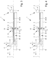
- FIG. 2 another device 1 for forming an imbricated stream 2 of overlapping sheets 3 is shown schematically in a side view. Identical or matching functional units, assemblies, components and other matching features in the Figures 1 and 2 shown device 1 are provided with the same reference numbers.
- the formation of an imbricated stream 2 of overlapping sheets 3 of paper, foil or cardboard takes place in the in 2 shown embodiment corresponding to the above-described imbricated stream formation in the device 1 1 .
- Deviating from the in 1 Device 1 shown is in accordance with the embodiment 2 provided that the shingle device 10 is designed to be adjustable in and/or counter to the transport direction X depending on the sheet length or the sheet format. this is in 2 shown schematically by the double arrow 21.
- the braking device 17, on the other hand, is non-adjustable in and/or opposite to the transport direction X of the sheets 3. In other words, this means that when the cutting length of the sheets 3 changes or when the sheet format changes, the shingling device 10 is offset, shifted or moved relative to the braking device 17 in such a way that a leading sheet is produced for each sheet length that is set 3 is braked approximately simultaneously at the front by the braking device 17 and at the rear by the delay unit 12 of the shingle device 10 .
- the stacking device 10 can be adjusted overall in or counter to the transport direction X of the sheet flow 2, i.e. the lifting unit 11 and the delay unit 12 are moved together, which for this purpose are in and/or counter to the transport direction X of the sheets 3 movable chassis or frame or carrier can be included or mounted. In principle, however, it is also possible that if the suction belt 13 extends sufficiently in the transport direction X, only the beater shaft 15 with the beater 16 is adjusted in or against the transport direction X.
- a suction profile 22 is provided between the shingling device 10 and the braking device 17 below the high-speed conveyor belt 9, which profile is designed as a hollow profile and is connected to a suction device (not shown), such as a suction fan.
- a suction device such as a suction fan.
- each conveyor belt 9 is preferably assigned a suction profile 22 .
- a first suction section 24 is formed between the shingling device 10 and the braking device 17, and a further suction section 25 is formed in the area between the shingling device 10 and the cross-cutting device 5.
- a negative pressure acts on the sheets 3 at least in the area of the leading edge of the sheets 3 via the suction profile 22 and the conveyor belt 9. The applied negative pressure prevents the leading edge of a sheet 3 from becoming detached.
- the formation of the suction section 24 means that the following sheet 3 is transported further in a defined position after it has passed the shingling device 10 . It is thus possible for the arches 3 to overlap in a defined manner without the arches 3 interfering with one another.
- the suction profile 22 preferably extends over the entire length of the area between the cross-cutting device 5 and the braking device 17. In the area in front of the shingling device 10, the further suction section 25 is formed by the suction profile 22.
- the negative pressure applied to the suction profile 22 should be significantly less strong in the area of the suction section 24 following the shingling device 10 in the transport direction X than the negative pressure present in the area of the further suction section 25 between the cross-cutting device 5 and the shingling device 10.
- a section 23 is provided on which no negative pressure or a comparatively less strong negative pressure is applied. In this way, the sheet 3 can be lifted in the area 23 and pressed against the suction belt 13 in a simple manner.
- the lifting unit 11 therefore does not have to counteract a negative pressure that would hold the trailing edge of the sheet 3 on the fast-moving conveyor belt 9 . It is thus possible for the trailing sheet 3 to be transported in the correct location and position under the leading sheet 3 that has been folded up, while at the same time the trailing edge of the sheet can be pressed against the suction belt 13 by the beater 16 without being adversely affected.
- the suction profile 22 can preferably be formed by a continuous hollow profile.
- the different levels of vacuum in the area of the suction section 24 and the suction section 25 can be achieved by a barrier or seal in the area of the scale device 10 .
- a low negative pressure is generated in the intake path 24 via the barrier.
- the pressure reduction in the area of the intake section 24 compared to the ambient pressure is preferably significantly lower than the pressure reduction in the area of the intake section 25.
- the barrier in the profile that forms the suction sections 24, 25 is designed to be movable, in particular displaceable, in and/or counter to the transport direction X of the sheets 3.
- the length of the intake section 24 can be adapted to the sheet format in a simple manner by adjusting the lock.
- the length of the suction section 25 is also changed, so that the sheets 3 are transported in a defined position and in the correct position from the cross-cutting device 5 to the shingling device 10 .
- the movable barrier is designed to be adjustable together with the lifting unit 11 and/or the entire shingling device 10 in and/or counter to the transport direction X of the sheets 3.
- a carriage (not shown), a scaffolding or a frame can be provided in which the shingling device 10 and the movable barrier are arranged, the carriage being able to be moved in and/or counter to the transport direction X of the sheets 3 .
- the device 1 can easily be set to a new or changed sheet format.
- suction belt 13 of the shingling device 10 extends over a sufficiently long distance in the transport direction X of the sheets, it can also be provided that only the lifting unit 11 and the movable lock are adjusted together in and/or counter to the transport direction X of the sheets 3.
- FIG. 3 another device 1 for forming an imbricated stream 2 of overlapping sheets 3 is shown schematically in a side view. Identical or matching functional units, assemblies, components and other matching features in the Figures 1, 2 and 3 shown device 1 are provided with the same reference numerals.
- the formation of an imbricated stream 2 of overlapping sheets 3 of paper, foil or cardboard takes place in the in 3 shown embodiment corresponding to the above-described imbricated stream formation in the device 1 1 .
- Deviating from the device 1 from 2 is the braking device 17 in and/or counter to the transport direction X of the sheets 3 according to the double arrow 21 designed to be displaceable or adjustable in order to be able to adapt the device 1 to a changed sheet format.
- the scale device 10 is in 3 shown device 1 fixed in position and thus not in and / or opposite to the transport direction X of the sheets 3 adjustable.
- the intake section 24 is in accordance with 3 formed by at least one telescoping suction profile, which consists of telescoping suction profile sections 26 and 27 and is connected to a suction device.
- the suction profile section 27 is preferably arranged in a stationary manner and the suction profile section 26 is preferably designed to be displaceable in and/or counter to the transport direction X of the sheets 3 .
- the length of the intake section 24 can also be adapted to the sheet format.
- a further device 1 for forming an imbricated stream 2 of overlapping sheets 3 is shown schematically in a side view.
- Identical or matching functional units, assemblies, components and other matching features in the Figures 1, 2 , 3 and 4 shown device 1 are provided with the same reference numerals.
- the formation of an imbricated stream 2 of overlapping sheets 3 of paper, foil or cardboard takes place in the in 2 shown embodiment corresponding to the above-described imbricated stream formation in the device 1 1 .
- the suction section 24 is formed from at least 2 suction profiles 28 and 29 that mesh with one another and that can overlap at least in sections transversely to the transport direction X of the sheets 3 .
- the suction profiles 28, 29 are in turn connected to at least one suction device. Crosswise to the direction of transport X of the sheets 3, the combing suction profiles 28, 29 can be formed in an alternating manner.
- the suction profile 29 is level with the front edge of the suction profile 28, the maximum length of the suction section 24 has been reached. If the suction profiles 28, 29 are pushed into one another so as to mesh, for example the suction profile 28 counter to the transport direction X of the sheets, the length of the suction path 24 is reduced.
Applications Claiming Priority (5)
| Application Number | Priority Date | Filing Date | Title |
|---|---|---|---|
| DE102017005661 | 2017-06-14 | ||
| DE102018103563 | 2018-02-16 | ||
| DE102018103597 | 2018-02-19 | ||
| EP18734471.8A EP3619153B1 (de) | 2017-06-14 | 2018-06-14 | Vorrichtung und verfahren zur bildung eines schuppenstroms von unterlappenden bögen |
| PCT/EP2018/065834 WO2018229205A1 (de) | 2017-06-14 | 2018-06-14 | Vorrichtung und verfahren zum lagedefinierten transport von bögen |
Related Parent Applications (2)
| Application Number | Title | Priority Date | Filing Date |
|---|---|---|---|
| EP18734471.8A Division EP3619153B1 (de) | 2017-06-14 | 2018-06-14 | Vorrichtung und verfahren zur bildung eines schuppenstroms von unterlappenden bögen |
| EP18734471.8A Division-Into EP3619153B1 (de) | 2017-06-14 | 2018-06-14 | Vorrichtung und verfahren zur bildung eines schuppenstroms von unterlappenden bögen |
Publications (1)
| Publication Number | Publication Date |
|---|---|
| EP4144677A1 true EP4144677A1 (de) | 2023-03-08 |
Family
ID=62750945
Family Applications (2)
| Application Number | Title | Priority Date | Filing Date |
|---|---|---|---|
| EP22203800.2A Pending EP4144677A1 (de) | 2017-06-14 | 2018-06-14 | Vorrichtung und verfahren zum lagedefinierten transport von bögen |
| EP18734471.8A Active EP3619153B1 (de) | 2017-06-14 | 2018-06-14 | Vorrichtung und verfahren zur bildung eines schuppenstroms von unterlappenden bögen |
Family Applications After (1)
| Application Number | Title | Priority Date | Filing Date |
|---|---|---|---|
| EP18734471.8A Active EP3619153B1 (de) | 2017-06-14 | 2018-06-14 | Vorrichtung und verfahren zur bildung eines schuppenstroms von unterlappenden bögen |
Country Status (8)
| Country | Link |
|---|---|
| US (1) | US11352232B2 (pl) |
| EP (2) | EP4144677A1 (pl) |
| JP (2) | JP7433218B2 (pl) |
| KR (1) | KR102357229B1 (pl) |
| DE (1) | DE102018114252A1 (pl) |
| ES (1) | ES2962982T3 (pl) |
| PL (1) | PL3619153T3 (pl) |
| WO (1) | WO2018229205A1 (pl) |
Citations (5)
| Publication number | Priority date | Publication date | Assignee | Title |
|---|---|---|---|---|
| DE3812685A1 (de) | 1988-04-16 | 1989-10-26 | Bielomatik Leuze & Co | Verzoegerungs-vorrichtung fuer bogenlagen |
| DE9103137U1 (pl) * | 1991-03-15 | 1991-06-13 | Georg Spiess Gmbh, 8906 Gersthofen, De | |
| EP0503531A1 (de) * | 1991-03-15 | 1992-09-16 | Georg Spiess GmbH | Vorrichtung zur Bildung einer Folge von sich unterlappenden Gegenständen |
| DE10103040A1 (de) | 2000-05-16 | 2001-11-22 | Heidelberger Druckmasch Ag | Vorrichtung und Verfahren zur Bildung einer Folge von unterlappten Bögen |
| US20150069696A1 (en) * | 2012-04-27 | 2015-03-12 | Andreas Schilling | Apparatus for overlapping and stacking sheets |
Family Cites Families (8)
| Publication number | Priority date | Publication date | Assignee | Title |
|---|---|---|---|---|
| JP2601959B2 (ja) * | 1990-10-15 | 1997-04-23 | 富士写真フイルム株式会社 | シート搬送区分装置 |
| JP2000296960A (ja) | 1999-04-14 | 2000-10-24 | Mitsubishi Heavy Ind Ltd | シート積上げ装置 |
| JP4056812B2 (ja) * | 2002-07-11 | 2008-03-05 | ハイニックス株式会社 | 断裁排出装置 |
| JP2008264967A (ja) * | 2007-04-24 | 2008-11-06 | Komori Corp | シーター装置 |
| US7942406B2 (en) * | 2008-08-22 | 2011-05-17 | Hinix Co., Ltd. | Roll feeder |
| DE102008060394B4 (de) * | 2008-12-03 | 2019-08-14 | Bw Papersystems Hamburg Gmbh | Vorrichtung und Verfahren zum Bilden eines Stroms sich überlappender Bögen oder Bogenstapel |
| DE102012214629A1 (de) | 2012-08-17 | 2014-02-20 | Bielomatik Leuze Gmbh + Co. Kg | Vorrichtung zum Schuppen und Ablegen von Bögen auf einen Stapel |
| DE202016004428U1 (de) * | 2016-07-20 | 2017-10-23 | Barry-Wehmiller Papersystems, Inc. | Vorrichtung zum Aufbringen von Datenträgern auf eine Trägerbahn |
-
2018
- 2018-06-14 WO PCT/EP2018/065834 patent/WO2018229205A1/de unknown
- 2018-06-14 PL PL18734471.8T patent/PL3619153T3/pl unknown
- 2018-06-14 US US16/621,526 patent/US11352232B2/en active Active
- 2018-06-14 JP JP2020519846A patent/JP7433218B2/ja active Active
- 2018-06-14 ES ES18734471T patent/ES2962982T3/es active Active
- 2018-06-14 EP EP22203800.2A patent/EP4144677A1/de active Pending
- 2018-06-14 DE DE102018114252.8A patent/DE102018114252A1/de active Pending
- 2018-06-14 EP EP18734471.8A patent/EP3619153B1/de active Active
- 2018-06-14 KR KR1020207000855A patent/KR102357229B1/ko active IP Right Grant
-
2022
- 2022-04-08 JP JP2022064281A patent/JP2022093379A/ja not_active Revoked
Patent Citations (5)
| Publication number | Priority date | Publication date | Assignee | Title |
|---|---|---|---|---|
| DE3812685A1 (de) | 1988-04-16 | 1989-10-26 | Bielomatik Leuze & Co | Verzoegerungs-vorrichtung fuer bogenlagen |
| DE9103137U1 (pl) * | 1991-03-15 | 1991-06-13 | Georg Spiess Gmbh, 8906 Gersthofen, De | |
| EP0503531A1 (de) * | 1991-03-15 | 1992-09-16 | Georg Spiess GmbH | Vorrichtung zur Bildung einer Folge von sich unterlappenden Gegenständen |
| DE10103040A1 (de) | 2000-05-16 | 2001-11-22 | Heidelberger Druckmasch Ag | Vorrichtung und Verfahren zur Bildung einer Folge von unterlappten Bögen |
| US20150069696A1 (en) * | 2012-04-27 | 2015-03-12 | Andreas Schilling | Apparatus for overlapping and stacking sheets |
Also Published As
| Publication number | Publication date |
|---|---|
| JP7433218B2 (ja) | 2024-02-19 |
| EP3619153B1 (de) | 2023-08-02 |
| EP3619153C0 (de) | 2023-08-02 |
| WO2018229205A1 (de) | 2018-12-20 |
| KR20200024838A (ko) | 2020-03-09 |
| ES2962982T3 (es) | 2024-03-22 |
| US20200165094A1 (en) | 2020-05-28 |
| EP3619153A1 (de) | 2020-03-11 |
| US11352232B2 (en) | 2022-06-07 |
| KR102357229B1 (ko) | 2022-02-08 |
| JP2020524122A (ja) | 2020-08-13 |
| DE102018114252A1 (de) | 2018-12-20 |
| JP2022093379A (ja) | 2022-06-23 |
| PL3619153T3 (pl) | 2024-02-05 |
Similar Documents
| Publication | Publication Date | Title |
|---|---|---|
| EP0498068B1 (de) | Falzapparat, bei dem der Transport der Falzexemplare über Transportmittel, Bandrollen und Bänder erfolgt | |
| DE2939277A1 (de) | Verfahren und vorrichtung zum abbremsen und ueberlappen von papierbogen | |
| DE102015221661B4 (de) | Trennvorrichtungen zum Abtrennen von Abschnitten von einer Materialbahn, Bearbeitungsmaschine und ein Verfahren zum Abtrennen zumindest eines Abschnitts von einer Materialbahn | |
| EP1944259A2 (de) | Querschneider mit Längsschnitt | |
| DE4435988A1 (de) | Vorrichtung zum Abbremsen von Bogen | |
| EP2841367B1 (de) | Vorrichtung zum schuppen und ablegen von bögen auf einen stapel | |
| EP0732287A2 (de) | Vorrichtung zum Stabilisieren einer Warenbahn | |
| DE10011006A1 (de) | Vorrichtung zum Schneiden von Papierbahnen | |
| EP2268481B1 (de) | Vorrichtung und verfahren zur herstellung von beuteln | |
| EP3619152B1 (de) | Vorrichtung und verfahren zur bildung eines schuppenstroms von unterlappenden bögen | |
| WO2013160399A1 (de) | Saugfördervorrichtung zum transport von flachteilen, und anlage zum herste llen|von flachteilen umfassend einer solchen saugfördervorrichtung | |
| EP3619153B1 (de) | Vorrichtung und verfahren zur bildung eines schuppenstroms von unterlappenden bögen | |
| DE202018103354U1 (de) | Vorrichtung zum lagedefinierten Transport von Bögen | |
| DE102010027820B4 (de) | Verfahren und Vorrichtung zum Einfädeln einer Faserstoffbahn in einem Aufwickler | |
| EP3737630B1 (de) | Vorrichtung zum schneiden einer materialbahn in einzelne bögen mit einem bahnspeicher | |
| DE202018102617U1 (de) | Vorrichtung zur Bildung eines Schuppenstroms von unter- oder überlappenden Bögen | |
| EP3059195B1 (de) | Falzvorrichtung und Verfahren | |
| DE19624277C2 (de) | Vorrichtung zum Schneiden von Papierbahnen | |
| DE3036816A1 (de) | Verfahren zum zusammenfuehren einer endlosbahn mit kontinuierlich gefoerdertem flaechigem gut, sowie vorrichtung zur durchfuehrung des verfahrens | |
| DE1202118B (de) | Vorrichtung zum intermittierenden Foerdern von aus einer Stanze herauskommenden Bahnen oder Bahnteilen aus Papier, Karton od. dgl. | |
| DE3131101C2 (de) | Verfahren zum Querschneiden einer Warenbahn, insbes. aus Papier, Kunststoff oder Metall und Stapeln der geschnittenen Bogen sowie Vorrichtung zur Durchführung des Verfahrens | |
| EP1808392B1 (de) | Verfahren und Vorrichtung zur Verarbeitung einer Bedruckstoffbahn zu Sammelprodukten | |
| DE102006021901B4 (de) | Verfahren zum Längsfalzen von zu falzenden Produkten | |
| DE19654984C2 (de) | Vorrichtung zum Schneiden von Papierbahnen | |
| CH453062A (de) | Vorrichtung an einer Zuschneidemaschine für Papierbahnen, zum Abbremsen und Überlappen der abgeschnittenen Papierbogen |
Legal Events
| Date | Code | Title | Description |
|---|---|---|---|
| PUAI | Public reference made under article 153(3) epc to a published international application that has entered the european phase |
Free format text: ORIGINAL CODE: 0009012 |
|
| STAA | Information on the status of an ep patent application or granted ep patent |
Free format text: STATUS: THE APPLICATION HAS BEEN PUBLISHED |
|
| AC | Divisional application: reference to earlier application |
Ref document number: 3619153 Country of ref document: EP Kind code of ref document: P |
|
| AK | Designated contracting states |
Kind code of ref document: A1 Designated state(s): AL AT BE BG CH CY CZ DE DK EE ES FI FR GB GR HR HU IE IS IT LI LT LU LV MC MK MT NL NO PL PT RO RS SE SI SK SM TR |
|
| STAA | Information on the status of an ep patent application or granted ep patent |
Free format text: STATUS: REQUEST FOR EXAMINATION WAS MADE |
|
| 17P | Request for examination filed |
Effective date: 20230801 |
|
| RBV | Designated contracting states (corrected) |
Designated state(s): AL AT BE BG CH CY CZ DE DK EE ES FI FR GB GR HR HU IE IS IT LI LT LU LV MC MK MT NL NO PL PT RO RS SE SI SK SM TR |