EP4140598B1 - Kleberschmelzvorrichtung für eine kantenanleimmaschine - Google Patents
Kleberschmelzvorrichtung für eine kantenanleimmaschine Download PDFInfo
- Publication number
- EP4140598B1 EP4140598B1 EP21193074.8A EP21193074A EP4140598B1 EP 4140598 B1 EP4140598 B1 EP 4140598B1 EP 21193074 A EP21193074 A EP 21193074A EP 4140598 B1 EP4140598 B1 EP 4140598B1
- Authority
- EP
- European Patent Office
- Prior art keywords
- melting
- adhesive
- outlet
- channels
- accordance
- Prior art date
- Legal status (The legal status is an assumption and is not a legal conclusion. Google has not performed a legal analysis and makes no representation as to the accuracy of the status listed.)
- Active
Links
Images



Classifications
-
- B—PERFORMING OPERATIONS; TRANSPORTING
- B05—SPRAYING OR ATOMISING IN GENERAL; APPLYING FLUENT MATERIALS TO SURFACES, IN GENERAL
- B05C—APPARATUS FOR APPLYING FLUENT MATERIALS TO SURFACES, IN GENERAL
- B05C5/00—Apparatus in which liquid or other fluent material is projected, poured or allowed to flow on to the surface of the work
- B05C5/02—Apparatus in which liquid or other fluent material is projected, poured or allowed to flow on to the surface of the work the liquid or other fluent material being discharged through an outlet orifice by pressure, e.g. from an outlet device in contact or almost in contact, with the work
- B05C5/0204—Apparatus in which liquid or other fluent material is projected, poured or allowed to flow on to the surface of the work the liquid or other fluent material being discharged through an outlet orifice by pressure, e.g. from an outlet device in contact or almost in contact, with the work for applying liquid or other fluent material to the edges of essentially flat articles
-
- B—PERFORMING OPERATIONS; TRANSPORTING
- B05—SPRAYING OR ATOMISING IN GENERAL; APPLYING FLUENT MATERIALS TO SURFACES, IN GENERAL
- B05C—APPARATUS FOR APPLYING FLUENT MATERIALS TO SURFACES, IN GENERAL
- B05C11/00—Component parts, details or accessories not specifically provided for in groups B05C1/00 - B05C9/00
- B05C11/10—Storage, supply or control of liquid or other fluent material; Recovery of excess liquid or other fluent material
- B05C11/1042—Storage, supply or control of liquid or other fluent material; Recovery of excess liquid or other fluent material provided with means for heating or cooling the liquid or other fluent material in the supplying means upstream of the applying apparatus
Definitions
- the invention relates to an adhesive melting device for an edge banding machine, wherein the adhesive melting device has a melting chamber for receiving adhesive material to be melted, a melting device with an electrically heatable melting body for melting the adhesive material and a pressure piston movable in a feed direction for pressing the adhesive material located in the melting chamber against the melting body, wherein the melting body comprises a plurality of through-channels which extend in the feed direction and each have an inlet section facing the melting chamber and an outlet section facing away from the melting chamber.
- Such adhesive melting devices are used in edgebanding machines, with the aid of which a glued edge, often also referred to as a "edge band,” can be fed to one long side of a workpiece moving in a transport direction and glued to the long side.
- the workpiece with the glued edge is then usually fed to a post-processing station to achieve a continuous transition between the top and bottom sides of the workpiece and the edge band.
- the adhesive is melted using an adhesive melting device.
- the melted adhesive can then be fed into an adhesive application system on the edgebander to apply the adhesive to the long side of the workpiece, allowing the edgeband to be subsequently bonded to the long side.
- Adhesive melting devices of the type mentioned above have a melting chamber into which the adhesive material to be melted can be introduced. Furthermore, the adhesive melting devices have a melting device for melting the adhesive material.
- the melting device has a An electrically heatable melting body comprising a plurality of through-channels, each having an inlet section facing the melting chamber and an outlet section facing away from the melting chamber.
- the adhesive melting devices also have a pressure piston movable in a feed direction, with the aid of which the adhesive material introduced into the melting chamber can be pressed against the melting body in order to melt the adhesive material.
- the through-channels extend in the feed direction of the pressure piston. The molten adhesive material can be fed to the adhesive application system via the through-channels.
- Such adhesive melting devices are known, for example, from EP 3 403 728 A1 known.
- the object of the present invention is to further develop an adhesive melting device of the type mentioned at the outset in such a way that the adhesive material can be melted within a shorter time.
- the adhesive material introduced into the melting chamber can be pressed against the honeycomb structure of the melting body by means of the pressure piston.
- the honeycomb structure faces the melting chamber and forms a large surface area through which rapid heat transfer from the electrically heated melting body to the adhesive material can occur. This allows the adhesive material to melt within a short time. Furthermore, the honeycomb structure has the advantage that the melting body can be easily cleaned.
- the honeycomb structure has a plurality of polygonal cells, each forming an entrance section of a passage channel and separated by partition walls are separated from each other. Heat transfer from the heated melt body to the adhesive material can occur via the partition walls.
- the partition walls can have flat surfaces, at least in some areas, without recesses or undercuts. This reduces the risk of adhesive residues forming within the honeycomb structure.
- At least some of the cells are hexagonal in shape.
- the hexagonal cells each have two opposite and parallel long sides which are integrally connected to one another via two pairs of narrow sides aligned at an angle to one another, the long sides being longer than the narrow sides.
- the two pairs of narrow sides are designed identically and that the two long sides are designed identically.
- the long sides are at least twice as long as the short sides.
- each of the cells of the honeycomb structure transitions continuously in the feed direction into a round, in particular circular, cross-sectional exit section of a through-channel.
- each cell of the honeycomb structure is adjoined by a round, cross-sectional exit section of a through-channel, with the transition from the cells to the round exit sections being continuous.
- the through-channels thus have no steps or recesses where adhesive residues could form and complicate cleaning of the melt body.
- the polygonal cells of the honeycomb structure taper continuously in the feed direction.
- the flow cross-section of the polygonal cells continuously decreases in the feed direction. This results in a continuous increase in the flow velocity of the adhesive material. This counteracts the formation of so-called dead spots within the cells, where the flow velocity drops to zero. Such dead spots could lead to thermal decomposition or curing of the adhesive material, which could result in the formation of adhesive residues within the cells.
- exit sections of the through-channels which have a round cross-section, especially a circular cross-section, taper continuously in the feed direction. This leads to a continuous reduction in the flow cross-sections in the area of the exit sections and thus to an increasing flow velocity of the adhesive material in the exit sections. This counteracts the formation of adhesive residues in the exit sections.
- the melting device comprises, in addition to the melting body, a collecting body which adjoins the melting body in the feed direction.
- the collecting body has several collecting channels into which the through-channels of the melting body open and which guide the molten adhesive material to an outlet area of the collecting body.
- the molten adhesive material can flow from the through-channels of the melting body to an outlet area of the collecting body via the collecting channels.
- the collecting channels can be designed to be aerodynamically efficient.
- the collecting body can be detachably connected to the melting body. This allows the collecting body to be separated from the melting body, for example, for cleaning purposes.
- At least one through channel leads into each collecting channel.
- the collecting channels have a width and/or depth that increases towards the outlet area.
- the width and/or depth of at least one collecting channel increases continuously over its entire length.
- the collecting channels are aligned perpendicular to the through channels.
- the collecting body forms a collecting plate which has a front side facing the melting body and a rear side facing away from the melting body, wherein the collecting channels are arranged in the form of depressions on the front side.
- the front and back of the collecting plate are flat.
- the adhesive melting device has an outlet body, wherein the melting device is detachably connectable to the outlet body, wherein the collecting body is arranged between the melting body and the outlet body, and wherein the outlet body has an outlet opening for the molten adhesive material aligned with the outlet region of the collecting body.
- the molten adhesive material can reach the outlet opening of the outlet body, from which the adhesive material can be fed into an adhesive application system, with the aid of which the adhesive material can be applied to a longitudinal edge of a workpiece moving in a transport direction.
- the melting device can be separated from the outlet body.
- the area of the rear side of the melting body, against which the collecting body rests with its side facing the melting body, and/or the area of the front side of the outlet body, against which the collecting body rests with its side facing the outlet body, are preferably designed to be flat.
- the collecting body can be detachably connected to the melting body and the outlet body. This facilitates maintenance, especially cleaning, of the melting device.
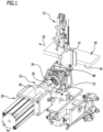
- FIG. 1 An adhesive application system 12 of the edge banding machine is shown schematically.
- the adhesive melting device 10 is connected to the adhesive application system 12.
- an adhesive material can be melted; this will be explained in more detail below.
- the adhesive application system 12 has a nozzle body 14.
- the workpiece 18 can be moved in a transport direction 20 by means of transport elements known per se and therefore not shown in the drawing, for example by means of transport rollers or transport chains.
- a glued edge can be glued to the long side 16 by means of the edge banding machine in a known manner.
- the adhesive melting device 10 has a melting chamber 22 into which the adhesive material to be melted can be introduced.
- Adhesive material can be designed, for example, in the form of an adhesive cartridge or in the form of adhesive granules.
- the adhesive melting device 10 also has a melting device 24 and an outlet body 25.
- the melting device 24 is in the Figures 2 to 6 shown schematically.
- Figure 2 also schematically shows the outlet body 25.
- the adhesive material introduced into the melting chamber 22 can be melted, and with the aid of the outlet body 25, the molten adhesive material can be fed into the adhesive application system 12.
- the outlet body 25 forms an interface between the melting device 24 and the adhesive application system 12.
- the adhesive melting device 10 has a pressure piston 26, which can be moved in a feed direction 30 by means of a feed unit 28. With the help of the pressure piston 26, the adhesive material introduced into the melting chamber 22 can be pressed against the melting device 24.
- the feed unit 28 can be configured, for example, as a piston-cylinder unit or, for example, as an electric motor. Such feed units 28 are known to those skilled in the art.
- the melting device 24 has a melting body 32 and a collecting body 34, which are arranged one behind the other in the feed direction 30.
- the outlet body 25 adjoins the collecting body 34 in the feed direction 30, this is shown in Figure 2 clearly.
- the melting body 32 has a plurality of through-channels 38 that extend in the feed direction 30 and each have an inlet section 40 facing the melting chamber 22 and an outlet section 42 facing away from the melting chamber 22.
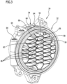
- the inlet sections 40 as a whole, form a honeycomb structure 44 facing the melting chamber 22.
- the honeycomb structure 44 has a plurality of polygonal cells 46, each forming an inlet section 40 of a through-channel 38 and separated from one another by partition walls 48. In the feed direction 30, each cell 46 is adjoined by an outlet section 42 of a through-channel 38, which extends to a flat rear side 50 of the melt body 32.
- the cells 46 are hexagonal in shape and have two opposing and parallel longitudinal sides 52, 54, which are integrally connected to one another via a first pair of narrow sides 56, 58 and a second pair of narrow sides 60, 62, wherein the narrow sides 56, 58 are arranged at an angle to one another and wherein the narrow sides 60, 62 are also arranged at an angle to one another.
- the longitudinal sides 52, 54 are significantly longer than the narrow sides 56, 58, 60, 62. In the illustrated embodiment, the longitudinal sides 52, 54 are more than twice as long as the narrow sides 56, 58, 60, 62.
- the cross sections of the outlet sections 42 of the through-channels 38 are round; in the illustrated embodiment, they are circular. Both the inlet sections 40 in the form of the cells 46 and the adjoining outlet sections 42 taper continuously in the feed direction 30, with the transition from the cells 46 to the outlet sections 42 also occurring continuously.
- the flow cross section of the through-channels 38 decreases continuously in the feed direction 30. This is particularly evident from Figure 5 This decreases significantly.
- the decreasing flow cross-section results in a continuous increase in the flow velocity of the adhesive material. This counteracts the risk of so-called dead spots forming within the through-channels 38, where the flow velocity drops to zero and where thermal decomposition or curing of the adhesive material could occur. The risk of adhesive residues forming within the through-channels 38 is therefore very low.
- the melting body 32 can be heated electrically.
- it has several cylindrical recesses 64 arranged between the outlet sections 42 of the through-channels 38, each of which can accommodate an electric heating cartridge.
- Such heating cartridges are known per se to those skilled in the art and are therefore not shown in the drawings for the sake of clarity.
- the honeycomb structure 44 enables rapid heat transfer from the electrically heated melting body 32 to the adhesive material.
- the adhesive material can therefore be melted within a short time.
- the through-channels 38 extend to the rear side 50 of the melting body 32.
- the rear side 50 is flat, and the collecting body 34 rests against the rear side 50.
- the collecting body 34 forms a collecting plate 66 and has a plurality of collecting channels 68, 70, 72, 74, 76, which are designed in the form of depressions and into which a plurality of through-channels 38 each open. Via the collecting channels 68, 70, 72, 74, 76, the molten adhesive material can flow from the through-channels 38 to an outlet region 78 of the collecting body 34.
- the flow cross-section of the collecting channels 68, 70, 72, 74, 76 increases in the direction of the outlet area 78.
- the collecting channels 68, 70, 72, 74, 76 widen and/or deepen as they approach the outlet area 78. This is particularly evident from Figure 6
- the increasing flow cross-section of the collecting channels 68, 70, 72, 74, 76 towards the outlet area 78 allows the intake of an increasing amount of molten adhesive material, which is fed to the collecting channels 68, 70, 72, 74, 76 via the through-channels 38, whereby the flow velocity of the adhesive material within the collecting channels 68, 70, 72, 74, 76 remains practically unchanged despite the increasing amount of adhesive material.
- the flow behavior of the adhesive material is therefore not impaired by the fact that several through channels 38 open into each collecting channel.
- the collecting plate 66 has a flat front side 79 facing the melting body 32 and a flat rear side 80 facing away from the melting body 32.
- the collecting channels 68, 70, 72, 74, 76 are arranged in the form of recesses on the front side 79.
- the rear side 80 is aligned parallel to the front side 79. With its rear side 80, the collecting plate 66 rests against a flat front side 82 of the outlet body 25, which has an outlet opening 84 aligned with the outlet region 78 of the collecting body 34, through which the molten adhesive material can be fed into the adhesive application system 12.
- the adhesive application system 12 has a connecting channel 86, which adjoins the outlet opening 84 and via which the molten adhesive material can be fed to the nozzle body 14.
- the adhesive material can be melted within a short time and fed to the adhesive application system 12.
- the melting device 24 can be easily cleaned.
- the melting body 32, the collecting body 34, and the outlet body 25 are detachably connected to one another.
Landscapes
- Coating Apparatus (AREA)
- Adhesives Or Adhesive Processes (AREA)
Description
- Die Erfindung betrifft eine Kleberschmelzvorrichtung für eine Kantenanleimmaschine, wobei die Kleberschmelzvorrichtung eine Schmelzkammer zum Aufnehmen von zu schmelzendem Klebermaterial, eine Schmelzeinrichtung mit einem elektrisch beheizbaren Schmelzkörper zum Schmelzen des Klebermaterials und einen in einer Vorschubrichtung bewegbaren Anpresskolben zum Anpressen des in der Schmelzkammer befindlichen Klebermaterials gegen den Schmelzkörper aufweist, wobei der Schmelzkörper eine Vielzahl von Durchgangskanäle umfasst, die sich in Vorschubrichtung erstrecken und jeweils einen der Schmelzkammer zugewandten Eingangsabschnitt und einen der Schmelzkammer abgewandten Ausgangsabschnitt aufweisen.
- Derartige Kleberschmelzvorrichtungen kommen bei Kantenanleimmaschinen zum Einsatz, mit deren Hilfe eine Anleimkante, die häufig auch als "Umleimer" bezeichnet wird, einer Längsseite eines in einer Transportrichtung bewegten Werkstücks zugeführt und mit der Längsseite verklebt werden kann. Anschließend wird das Werkstück mit der Anleimkante üblicherweise einer Nachbearbeitung zugeführt, um einen kontinuierlichen Übergang zwischen den Ober- und Unterseiten des Werkstücks und dem Umleimer zu erzielen.
- Zum Verkleben der Anleimkante mit der Längsseite des Werkstücks wird Klebermaterial mit Hilfe einer Kleberschmelzvorrichtung geschmolzen. Das geschmolzene Klebermaterial kann dann in ein Kleberauftragssystem der Kantenanleimmaschine eingespeist werden, um das Klebermaterial auf die Längsseite des Werkstücks aufzutragen, so dass anschließend die Anleimkante mit der Längsseite verklebt werden kann.
- Kleberschmelzvorrichtungen der eingangs genannten Art weisen eine Schmelzkammer auf, in die zu schmelzendes Klebermaterial eingebracht werden kann. Außerdem weisen die Kleberschmelzvorrichtungen eine Schmelzeinrichtung zum Schmelzen des Klebermaterials auf. Die Schmelzeinrichtung weist einen elektrisch beheizbaren Schmelzkörper auf, der eine Vielzahl von Durchgangskanäle umfasst, die jeweils einen der Schmelzkammer zugewandten Eingangsabschnitt und einen der Schmelzkammer abgewandten Ausgangsabschnitt aufweisen. Außerdem weisen die Kleberschmelzvorrichtungen einen in einer Vorschubrichtung bewegbaren Anpresskolben auf, mit dessen Hilfe das in die Schmelzkammer eingebrachte Klebermaterial gegen den Schmelzkörper gepresst werden kann, um das Klebermaterial zu schmelzen. Die Durchgangskanäle erstrecken sich in Vorschubrichtung des Anpresskolbens. Über die Durchgangskanäle kann das geschmolzene Klebermaterial dem Kleberauftragssystem zugeführt werden.
- Derartige Kleberschmelzvorrichtungen sind beispielsweise aus der
EP 3 403 728 A1 bekannt. - Aus der
EP 3 653 308 A1 ist eine Kleberschmelzvorrichtung mit den Merkmalen des Oberbegriffs von Patentanspruch 1 bekannt. - Aufgabe der vorliegenden Erfindung ist es, eine Kleberschmelzvorrichtung der eingangs genannten Art derart weiterzubilden, dass das Klebermaterial innerhalb kürzerer Zeit geschmolzen werden kann.
- Diese Aufgabe wird durch eine Kleberschmelzvorrichtung mit den Merkmalen von Patentanspruch 1 gelöst.
- Das in die Schmelzkammer eingebrachte Klebermaterial kann mittels des Anpresskolbens gegen die Wabenstruktur des Schmelzkörpers gepresst werden. Die Wabenstruktur ist der Schmelzkammer zugewandt und bildet eine große Oberfläche aus, über die eine schnelle Wärmeübertragung vom elektrisch beheizten Schmelzkörper zum Klebermaterial erfolgen kann. Dies ermöglicht es, das Klebermaterial innerhalb kurzer Zeit zu schmelzen. Darüber hinaus hat die Wabenstruktur den Vorteil, dass der Schmelzkörper auf einfache Weise gereinigt werden kann.
- Die Wabenstruktur weist eine Vielzahl mehreckiger Zellen auf, die jeweils einen Eingangsabschnitt eines Durchgangskanals ausbilden und durch Trennwände voneinander getrennt sind. Über die Trennwände kann die Wärmeübertragung vom beheizten Schmelzkörper zum Klebermaterial erfolgen. Die Trennwände können zumindest bereichsweise plane Oberflächen ohne Rücksprünge oder Hinterschnitte aufweisen. Dies verringert das Risiko, dass sich innerhalb der Wabenstruktur Rückstände von Klebermaterial ausbilden.
- Zumindest einige der Zellen sind sechseckförmig ausgestaltet.
- Von besonderem Vorteil ist es, wenn die sechseckförmigen Zellen jeweils zwei einander gegenüberliegende und parallel zueinander ausgerichtete Längsseiten aufweisen, die über zwei Paare von im Winkel zueinander ausgerichteten Schmalseiten einstückig miteinander verbunden sind, wobei die Längsseiten länger sind als die Schmalseiten.
- Insbesondere kann vorgesehen sein, dass die beiden Paare von Schmalseiten identisch ausgestaltet sind und dass die beiden Längsseiten identisch ausgestaltet sind.
- Als vorteilhaft hat es sich erwiesen, wenn die Längsseiten mindestens doppelt so lang sind wie die Schmalseiten.
- Bei einer bevorzugten Ausgestaltung der Erfindung geht jede der Zellen der Wabenstruktur in Vorschubrichtung kontinuierlich in einen im Querschnitt runden, insbesondere kreisförmigen Ausgangsabschnitt eines Durchgangskanals über. An die Zellen der Wabenstruktur schließt sich bei einer derartigen Ausgestaltung jeweils ein im Querschnitt runder Ausgangsabschnitt eines Durchgangskanals an, wobei der Übergang von den Zellen zu den runden Ausgangsabschnitten kontinuierlich erfolgt. Die Durchgangskanäle weisen somit keine Stufen oder Rücksprünge auf, an denen sich Rückstände von Klebermaterial ausbilden könnten und die die Reinigung des Schmelzkörpers erschweren könnten.
- Von Vorteil ist es, wenn sich die mehreckigen Zellen der Wabenstruktur in Vorschubrichtung kontinuierlich verjüngen. Bei einer derartigen Ausgestaltung der Erfindung verringert sich der Strömungsquerschnitt der mehreckigen Zellen in Vorschubrichtung kontinuierlich. Dies hat zur Folge, dass sich die Strömungsgeschwindigkeit des Klebermaterials kontinuierlich erhöht. Dadurch wird der Ausbildung sogenannter Totstellen innerhalb der Zellen entgegengewirkt, in denen die Strömungsgeschwindigkeit zu Null geht. Derartige Totstellen könnten zu einer thermischen Zersetzung oder zu einer Aushärtung des Klebermaterials führen, wodurch sich innerhalb der Zellen Rückstände von Klebermaterial ausbilden könnten.
- Günstig ist es, wenn sich die im Querschnitt runden, insbesondere kreisförmigen Ausgangsabschnitte der Durchgangskanäle in Vorschubrichtung kontinuierlich verjüngen. Dies führt zu einer kontinuierlichen Verringerung der Strömungsquerschnitte im Bereich der Ausgangsabschnitte und damit zu einer zunehmenden Strömungsgeschwindigkeit des Klebermaterials in den Ausgangsabschnitten. Dies wirkt der Ausbildung von Rückständen von Klebermaterial in den Ausgangsabschnitten entgegen.
- Besonders günstig ist es, wenn sich die Durchgangskanäle über ihre gesamte Länge kontinuierlich verjüngen.
- Bei einer vorteilhaften Ausgestaltung der Erfindung weist die Schmelzeinrichtung in Ergänzung zum Schmelzkörper einen Sammelkörper auf, der sich in Vorschubrichtung an den Schmelzkörper anschließt, wobei der Sammelkörper mehrere Sammelkanäle aufweist, in die die Durchgangskanäle des Schmelzkörpers einmünden und die das geschmolzene Klebermaterial zu einem Auslassbereich des Sammelkörpers führen. Über die Sammelkanäle kann das geschmolzene Klebermaterial von den Durchgangskanälen des Schmelzkörpers zu einem Auslassbereich des Sammelkörpers gelangen. Die Sammelkanäle können hierbei strömungsgünstig ausgestaltet sein.
- Von Vorteil ist es, wenn der Sammelkörper mit dem Schmelzkörper lösbar verbindbar ist. Dies erlaubt es, den Sammelkörper, beispielsweise zu Reinigungszwecken, vom Schmelzkörper zu trennen.
- In die Sammelkanäle mündet jeweils mindestens ein Durchgangskanal. Bevorzugt münden in jeden Sammelkanal mehrere Durchgangskanäle.
- Von Vorteil ist es, wenn in die Sammelkanäle in Richtung Auslassbereich aufeinanderfolgend mehrere Durchgangskanäle einmünden und sich der Strömungsquerschnitt der Sammelkanäle in Richtung Auslassbereich vergrößert. Der sich in Richtung auf den Auslassbereich vergrößernde Strömungsquerschnitt der Sammelkanäle erlaubt es, eine in Richtung Auslassbereich zunehmende Menge an geschmolzenem Klebermaterial aufzunehmen, das den Sammelkanälen über die Durchgangskanäle zugeführt wird, wobei sich die Strömungsgeschwindigkeit des Klebermaterials innerhalb der Sammelkanäle trotz der zunehmenden Menge an Klebermaterial praktisch nicht ändert. Das Strömungsverhalten des Klebermaterials wird also nicht dadurch beeinträchtigt, dass in die Sammelkanäle mehrere Durchgangskanäle einmünden.
- Bei einer bevorzugten Ausführungsform der Erfindung weisen die Sammelkanäle eine in Richtung Auslassbereich zunehmende Breite und/oder Tiefe auf.
- Von Vorteil ist es, wenn die Breite und/oder Tiefe zumindest eines Sammelkanals über dessen gesamte Länge kontinuierlich zunimmt.
- Günstig ist es, wenn die Sammelkanäle senkrecht zu den Durchgangskanälen ausgerichtet sind.
- Der Sammelkörper bildet bei einer bevorzugten Ausführungsform der Erfindung eine Sammelplatte aus, die eine dem Schmelzkörper zugewandte Vorderseite und eine dem Schmelzkörper abgewandte Rückseite aufweist, wobei die Sammelkanäle in Form von Vertiefungen an der Vorderseite angeordnet sind.
- Bevorzugt sind die Vorderseite und die Rückseite der Sammelplatte plan ausgestaltet.
- Günstig ist es, wenn die Rückseite der Sammelplatte parallel zur Vorderseite der Sammelplatte ausgerichtet ist.
- Bei einer besonders bevorzugten Ausführungsform der Erfindung weist die Kleberschmelzvorrichtung einen Auslasskörper auf, wobei die Schmelzeinrichtung mit dem Auslasskörper lösbar verbindbar ist, wobei der Sammelkörper zwischen dem Schmelzkörper und dem Auslasskörper angeordnet ist, und wobei der Auslasskörper eine fluchtend zum Auslassbereich des Sammelkörpers ausgerichtete Auslassöffnung für das geschmolzene Klebermaterial aufweist. Über die Sammelkanäle und den Auslassbereich des Sammelkörpers kann das geschmolzene Klebermaterial zur Auslassöffnung des Auslasskörpers gelangen, von der aus das Klebermaterial in ein Kleberauftragssystem eingespeist werden kann, mit dessen Hilfe das Klebermaterial auf eine Längskante eines in einer Transportrichtung bewegten Werkstückes aufgetragen werden kann. Zu Wartungszwecken, insbesondere zur Reinigung, kann die Schmelzeinrichtung vom Auslasskörper getrennt werden.
- Der Bereich der Rückseite des Schmelzkörpers, an dem der Sammelkörper mit seiner dem Schmelzkörper zugewandten Seite anliegt, und/oder der Bereich der Vorderseite des Auslasskörpers, an dem der Sammelkörper mit seiner dem Auslasskörper zugewandten Seite anliegt, sind bevorzugt plan ausgestaltet.
- Günstig ist es, wenn der Sammelkörper mit dem Schmelzkörper und dem Auslasskörper lösbar verbindbar ist. Dies erleichtert die Wartung, insbesondere die Reinigung, der Schmelzeinrichtung.
- Die nachfolgende Beschreibung einer vorteilhaften Ausführungsform der Erfindung dient im Zusammenhang mit der Zeichnung der näheren Erläuterung. Es zeigen:
- Figur 1:
- eine perspektivische Darstellung einer Kleberschmelzvorrichtung für eine Kantenanleimmaschine;
- Figur 2:
- eine Explosionszeichnung einer Schmelzeinrichtung und eines Auslasskörpers der Kleberschmelzvorrichtung aus
Figur 1 ; - Figur 3:
- eine perspektivische Darstellung der Schmelzeinrichtung schräg von vorne;
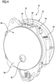
- Figur 4:
- eine perspektivische Darstellung der Schmelzeinrichtung schräg von hinten;
- Figur 5:
- eine Schnittansicht eines Schmelzkörpers der Schmelzeinrichtung;
- Figur 6:
- eine Schnittansicht eines Sammelkörpers der Schmelzeinrichtung.
- In der Zeichnung ist eine vorteilhafte Ausführungsform einer erfindungsgemäßen Kleberschmelzvorrichtung 10 schematisch dargestellt, die bei einer Kantenanleimmaschine zum Einsatz kommt. Derartige Kantenanleimmaschinen sind dem Fachmann an sich bekannt. In
Figur 1 ist ein Kleberauftragssystem 12 der Kantenanleimmaschine schematisch dargestellt. Die Kleberschmelzvorrichtung 10 ist an das Kleberauftragssystem 12 angeschlossen. Mit Hilfe der Kleberschmelzvorrichtung 10 kann ein Klebermaterial geschmolzen werden, dies wird nachfolgend noch näher erläutert, und mittels des Kleberauftragssystems 12 kann das geschmolzene Klebermaterial auf eine Längsseite 16 eines Werkstücks 18 aufgetragen werden. Zu diesem Zweck weist das Kleberauftragssystem einen Düsenkörper 14 auf. Das Werkstück 18 kann mit Hilfe von an sich bekannten und deshalb in der Zeichnung nicht dargestellten Transportgliedern, beispielsweise mit Hilfe von Transportrollen oder Transportketten, in einer Transportrichtung 20 bewegt werden. Nach dem Auftragen des Klebermaterials auf die Längsseite 16 kann mittels der Kantenanleimmaschine in bekannter Weise eine Anleimkante mit der Längsseite 16 verklebt werden. - Die Kleberschmelzvorrichtung 10 weist eine Schmelzkammer 22 auf, in die zu schmelzendes Klebermaterial eingebracht werden kann. Das zu schmelzende Klebermaterial kann beispielsweise in Form einer Kleberpatrone oder in Form eines Klebergranulates ausgestaltet sein.
- Die Kleberschmelzvorrichtung 10 weist außerdem eine Schmelzeinrichtung 24 und einen Auslasskörper 25 auf. Die Schmelzeinrichtung 24 ist in den
Figuren 2 bis 6 schematisch dargestellt.Figur 2 zeigt schematisch auch den Auslasskörper 25. Mit Hilfe der Schmelzeinrichtung 24 kann das in die Schmelzkammer 22 eingebrachte Klebermaterial geschmolzen werden, und mit Hilfe des Auslasskörpers 25 kann das geschmolzene Klebermaterial in das Kleberauftragssystem 12 eingespeist werden. Der Auslasskörper 25 bildet eine Schnittstelle zwischen der Schmelzeinrichtung 24 und dem Kleberauftragssystem 12 aus. - Die Kleberschmelzvorrichtung 10 weist einen Anpresskolben 26 auf, der mit Hilfe eines Vorschubaggregates 28 in einer Vorschubrichtung 30 bewegt werden kann. Mit Hilfe des Anpresskolbens 26 kann das in die Schmelzkammer 22 eingebrachte Klebermaterial gegen die Schmelzeinrichtung 24 gepresst werden. Das Vorschubaggregat 28 kann beispielsweise als Kolben-Zylinderaggregat oder beispielsweise als Elektromotor ausgestaltet sein. Derartige Vorschubaggregate 28 sind dem Fachmann bekannt.
- Die Schmelzeinrichtung 24 weist einen Schmelzkörper 32 und einen Sammelkörper 34 auf, die in Vorschubrichtung 30 hintereinander angeordnet sind. An den Sammelkörper 34 schließt sich in Vorschubrichtung 30 der Auslasskörper 25 an, dies wird aus
Figur 2 deutlich. - Der Schmelzkörper 32 weist eine Vielzahl von Durchgangskanäle 38 auf, die sich in Vorschubrichtung 30 erstrecken und jeweils einen der Schmelzkammer 22 zugewandten Eingangsabschnitt 40 und einen der Schmelzkammer 22 abgewandten Ausgangsabschnitt 42 aufweisen. Die Eingangsabschnitte 40 bilden in ihrer Gesamtheit eine der Schmelzkammer 22 zugewandte Wabenstruktur 44 aus.
- Die Wabenstruktur 44 weist eine Vielzahl mehreckiger Zellen 46 auf, die jeweils einen Eingangsabschnitt 40 eines Durchgangskanals 38 ausbilden und durch Trennwände 48 voneinander getrennt sind. In Vorschubrichtung 30 schließt sich an jede Zelle 46 ein Ausgangsabschnitt 42 eines Durchgangskanals 38 an, der sich bis zu einer plan ausgestalteten Rückseite 50 des Schmelzkörpers 32 erstreckt.
- Wie insbesondere aus
Figur 2 und3 deutlich wird, sind mehrere der Zellen 46 sechseckförmig ausgestaltet und weisen zwei einander gegenüberliegende und parallel zueinander ausgerichtete Längsseiten 52, 54 auf, die über ein erstes Paar von Schmalseiten 56, 58 und ein zweites Paar von Schmalseiten 60, 62 einstückig miteinander verbunden sind, wobei die Schmalseiten 56, 58 im Winkel zueinander angeordnet sind und wobei die Schmalseiten 60, 62 ebenfalls im Winkel zueinander angeordnet sind. Die Längsseiten 52, 54 sind deutlich länger als die Schmalseiten 56, 58, 60, 62. Im dargestellten Ausführungsbeispiel sind die Längsseiten 52, 54 mehr als doppelt so lang wie die Schmalseiten 56, 58, 60, 62. - Die Querschnitte der Ausgangsabschnitte 42 der Durchgangskanäle 38 sind rund ausgestaltet, im dargestellten Ausführungsbeispiel sind sie kreisförmig ausgestaltet. Sowohl die Eingangsabschnitte 40 in Form der Zellen 46 als auch die sich an diese anschließenden Ausgangsabschnitte 42 verjüngen sich kontinuierlich in Vorschubrichtung 30, wobei auch der Übergang von den Zellen 46 zu den Ausgangsabschnitten 42 kontinuierlich erfolgt. Somit verringert sich der Strömungsquerschnitt der Durchgangskanäle 38 in Vorschubrichtung 30 kontinuierlich. Dies wird insbesondere aus
Figur 5 deutlich. Der sich verringernde Strömungsquerschnitt hat zur Folge, dass sich die Strömungsgeschwindigkeit des Klebermaterials kontinuierlich erhöht. Dadurch wird der Gefahr entgegengewirkt, dass sich innerhalb der Durchgangskanäle 38 sogenannte Totstellen ausbilden, in denen die Strömungsgeschwindigkeit zu Null geht und an denen eine thermische Zersetzung oder eine Aushärtung des Klebermaterials erfolgen könnte. Die Gefahr, dass sich innerhalb der Durchgangskanäle 38 Rückstände von Klebermaterial ausbilden, ist deshalb sehr gering. - Der Schmelzkörper 32 kann elektrisch beheizt werden. Zu diesem Zweck weist er mehrere zylindrische Ausnehmungen 64 auf, die zwischen den Ausgangsabschnitten 42 der Durchgangskanäle 38 angeordnet sind und in die jeweils eine elektrische Heizpatrone eingesetzt werden kann. Derartige Heizpatronen sind dem Fachmann an sich bekannt und daher zur Erzielung einer besseren Übersicht in der Zeichnung nicht dargestellt.
- Die Wabenstruktur 44 ermöglicht eine schnelle Wärmeübertragung vom elektrisch beheizten Schmelzkörper 32 zum Klebermaterial. Das Klebermaterial kann daher innerhalb kurzer Zeit geschmolzen werden.
- Wie bereits erwähnt, erstrecken sich die Durchgangskanäle 38 bis zur Rückseite 50 des Schmelzkörpers 32. Die Rückseite 50 ist plan ausgestaltet, und an der Rückseite 50 liegt der Sammelkörper 34 an.
- Der Sammelkörper 34 bildet eine Sammelplatte 66 aus und weist mehrere Sammelkanäle 68, 70, 72, 74, 76 auf, die in Form von Vertiefungen ausgestaltet sind und in die jeweils mehrere Durchgangskanäle 38 einmünden. Über die Sammelkanäle 68, 70, 72, 74, 76 kann das geschmolzene Klebermaterial von den Durchgangskanälen 38 zu einem Auslassbereich 78 des Sammelkörpers 34 gelangen.
- Der Strömungsquerschnitt der Sammelkanäle 68, 70, 72, 74, 76 vergrößert sich in Richtung Auslassbereich 78. Zu diesem Zweck verbreitern und/oder vertiefen sich die Sammelkanäle 68, 70, 72, 74, 76 mit zunehmender Annäherung an den Auslassbereich 78. Dies wird insbesondere aus
Figur 6 deutlich. Der sich in Richtung Auslassbereich 78 vergrößernde Strömungsquerschnitt der Sammelkanäle 68, 70, 72, 74, 76 erlaubt es, eine in Richtung Auslassbereich 78 zunehmende Menge an geschmolzenem Klebermaterial aufzunehmen, das den Sammelkanälen 68, 70, 72, 74, 76 über die Durchgangskanäle 38 zugeführt wird, wobei sich die Strömungsgeschwindigkeit des Klebermaterials innerhalb der Sammelkanäle 68, 70, 72, 74, 76 trotz der zunehmenden Menge an Klebermaterial praktisch nicht ändert. Das Strömungsverhalten des Klebermaterials wird also nicht dadurch beeinträchtigt, dass in jeden Sammelkanal mehrere Durchgangskanäle 38 einmünden. - Die Sammelplatte 66 weist eine plane, dem Schmelzkörper 32 zugewandte Vorderseite 79 und eine plane, dem Schmelzkörper 32 abgewandte Rückseite 80 auf. Die Sammelkanäle 68, 70, 72, 74, 76 sind in Form von Vertiefungen an der Vorderseite 79 angeordnet. Die Rückseite 80 ist parallel zur Vorderseite 79 ausgerichtet. Mit ihrer Rückseite 80 liegt die Sammelplatte 66 an einer plan ausgestalteten Vorderseite 82 des Auslasskörpers 25 an, der eine fluchtend zum Auslassbereich 78 des Sammelkörpers 34 ausgerichtete Auslassöffnung 84 aufweist, über die das geschmolzene Klebermaterial in das Kleberauftragssystem 12 eingespeist werden kann. Zu diesem Zweck weist das Kleberauftragssystem 12 einen Verbindungskanal 86 auf, der sich an die Auslassöffnung 84 anschließt und über den das geschmolzene Klebermaterial dem Düsenkörper 14 zugeführt werden kann.
- Mit Hilfe der Kleberschmelzvorrichtung 10 kann das Klebermaterial innerhalb kurzer Zeit geschmolzen und dem Kleberauftragssystem 12 zugeführt werden. Die Schmelzeinrichtung 24 kann auf einfache Weise gereinigt werden. Zu diesem Zweck sind der Schmelzkörper 32, der Sammelkörper 34 und der Auslasskörper 25 lösbar miteinander verbunden.
Claims (13)
- Kleberschmelzvorrichtung für eine Kantenanleimmaschine, wobei die Kleberschmelzvorrichtung (10) eine Schmelzkammer (22) zum Aufnehmen von zu schmelzendem Klebermaterial, eine Schmelzeinrichtung (24) mit einem elektrisch beheizbaren Schmelzkörper (32) zum Schmelzen des Klebermaterials und einen in einer Vorschubrichtung (30) bewegbaren Anpresskolben (26) zum Anpressen des in der Schmelzkammer (22) befindlichen Klebermaterials gegen den Schmelzkörper (32) aufweist, wobei der Schmelzkörper (32) eine Vielzahl von Durchgangskanäle (38) umfasst, die sich in Vorschubrichtung (30) erstrecken und jeweils einen der Schmelzkammer (22) zugewandten Eingangsabschnitt (40) und einen der Schmelzkammer (22) abgewandten Ausgangsabschnitt (42) aufweisen, wobei die Eingangsabschnitte (40) eine Wabenstruktur (44) ausbilden, wobei die Wabenstruktur (44) eine Vielzahl mehreckiger Zellen (46) aufweist, die jeweils einen Eingangsabschnitt (40) eines Durchgangskanals (38) ausbilden und durch Trennwände (48) voneinander getrennt sind, dadurch gekennzeichnet, dass zumindest einige der Zellen (46) sechseckförmig ausgestaltet sind.
- Kleberschmelzvorrichtung nach Anspruch 1, dadurch gekennzeichnet, dass die sechseckförmigen Zellen (46) jeweils zwei einander gegenüberliegende und parallel zueinander ausgerichtete Längsseiten (52, 54) aufweisen, die über zwei Paare von im Winkel zueinander ausgerichteten Schmalseiten (56, 58; 60, 62) einstückig miteinander verbunden sind, wobei die Längsseiten (52, 54) länger sind als die Schmalseiten (56, 58, 60, 62).
- Kleberschmelzvorrichtung nach Anspruch 2, dadurch gekennzeichnet, dass die Längsseiten (52, 54) mindestens doppelt so lang sind wie die Schmalseiten (56, 58, 60, 62).
- Kleberschmelzvorrichtung nach einem der Ansprüche 1 bis 3, dadurch gekennzeichnet, dass jede der mehreckigen Zellen (46) der Wabenstruktur (44) in Vorschubrichtung (30) kontinuierlich in einen im Querschnitt runden Ausgangsabschnitt (42) eines Durchgangskanals (38) übergeht.
- Kleberschmelzvorrichtung nach Anspruch 4, dadurch gekennzeichnet, dass sich die mehreckigen Zellen (46) in Vorschubrichtung (30) kontinuierlich verjüngen.
- Kleberschmelzvorrichtung nach Anspruch 4 oder 5, dadurch gekennzeichnet, dass sich die im Querschnitt runden Ausgangsabschnitte (42) der Durchgangskanäle (38) in Vorschubrichtung (30) kontinuierlich verjüngen.
- Kleberschmelzvorrichtung nach einem der voranstehenden Ansprüche, dadurch gekennzeichnet, dass sich die Durchgangskanäle (38) über ihre gesamte Länge kontinuierlich verjüngen.
- Kleberschmelzvorrichtung nach einem der voranstehenden Ansprüche, dadurch gekennzeichnet, dass die Schmelzeinrichtung (24) einen Sammelkörper (34) aufweist, der sich in Vorschubrichtung (30) an den Schmelzkörper (32) anschließt, wobei der Sammelkörper (34) mehrere Sammelkanäle (68, 70, 72, 74, 76) aufweist, in die die Durchgangskanäle (38) des Schmelzkörpers (32) einmünden und die das geschmolzene Klebermaterial zu einem Auslassbereich (78) des Sammelkörpers (34) führen.
- Kleberschmelzvorrichtung nach Anspruch 8, dadurch gekennzeichnet, dass in die Sammelkanäle (68, 70, 72, 74, 76) in Richtung Auslassbereich (78) aufeinanderfolgend mehrere Durchgangskanäle (38) einmünden und sich der Strömungsquerschnitt der Sammelkanäle (68, 70, 72, 74, 76) in Richtung Auslassbereich (78) vergrößert.
- Kleberschmelzvorrichtung nach Anspruch 9, dadurch gekennzeichnet, dass die Sammelkanäle (68, 70, 72, 74, 76) eine in Richtung Auslassbereich (78) zunehmende Breite und/oder Tiefe aufweisen.
- Kleberschmelzvorrichtung nach Anspruch 10, dadurch gekennzeichnet, dass die Breite und/oder Tiefe zumindest eines Sammelkanals (68, 70, 72, 74, 76) über dessen gesamte Länge kontinuierlich zunimmt.
- Kleberschmelzvorrichtung nach einem der Ansprüche 8 bis 11, dadurch gekennzeichnet, dass der Sammelkörper (34) eine Sammelplatte (66) ausbildet, die eine dem Schmelzkörper (32) zugewandte Vorderseite (79) und eine dem Schmelzkörper (32) abgewandte Rückseite (80) aufweist, wobei die Sammelkanäle (68, 70, 72, 74, 76) in Form von Vertiefungen an der Vorderseite (79) angeordnet sind.
- Kleberschmelzvorrichtung nach einem der Ansprüche 8 bis 12, dadurch gekennzeichnet, dass die Kleberschmelzvorrichtung (10) einen Auslasskörper (25) aufweist, wobei die Schmelzeinrichtung (24) mit dem Auslasskörper (25) lösbar verbindbar ist, wobei der Sammelkörper (34) zwischen dem Schmelzkörper (32) und dem Auslasskörper (25) angeordnet ist, und wobei der Auslasskörper (25) eine fluchtend zum Auslassbereich (78) des Sammelkörpers (34) ausgerichtete Auslassöffnung (84) für das geschmolzene Klebermaterial aufweist.
Priority Applications (1)
| Application Number | Priority Date | Filing Date | Title |
|---|---|---|---|
| EP21193074.8A EP4140598B1 (de) | 2021-08-25 | 2021-08-25 | Kleberschmelzvorrichtung für eine kantenanleimmaschine |
Applications Claiming Priority (1)
| Application Number | Priority Date | Filing Date | Title |
|---|---|---|---|
| EP21193074.8A EP4140598B1 (de) | 2021-08-25 | 2021-08-25 | Kleberschmelzvorrichtung für eine kantenanleimmaschine |
Publications (2)
| Publication Number | Publication Date |
|---|---|
| EP4140598A1 EP4140598A1 (de) | 2023-03-01 |
| EP4140598B1 true EP4140598B1 (de) | 2025-06-18 |
Family
ID=77499750
Family Applications (1)
| Application Number | Title | Priority Date | Filing Date |
|---|---|---|---|
| EP21193074.8A Active EP4140598B1 (de) | 2021-08-25 | 2021-08-25 | Kleberschmelzvorrichtung für eine kantenanleimmaschine |
Country Status (1)
| Country | Link |
|---|---|
| EP (1) | EP4140598B1 (de) |
Family Cites Families (7)
| Publication number | Priority date | Publication date | Assignee | Title |
|---|---|---|---|---|
| DE3109369C2 (de) * | 1981-03-12 | 1984-01-12 | Reich Spezialmaschinen GmbH, 7440 Nürtingen | Schmelz- und Auftragsvorrichtung für Schmelzkleber |
| EP0342254A1 (de) * | 1988-05-18 | 1989-11-23 | Nordson Corporation | Vorrichtung zum Aufschmelzen von hochpolymeren, thermoplastischen Werkstoffen, insbesondere Klebstoffen |
| US7626143B2 (en) * | 2005-02-17 | 2009-12-01 | Scott Richard Miller | Apparatus and method for processing hot melt adhesives |
| TW201511846A (zh) * | 2013-09-17 | 2015-04-01 | Technos Co Ltd | 熱熔膠槍 |
| DE102017111013A1 (de) | 2017-05-19 | 2018-11-22 | Holz-Her Gmbh | Kleberauftragsvorrichtung |
| CN108160411B (zh) * | 2018-02-06 | 2024-01-30 | 北京延锋北汽汽车内饰件有限公司 | 一种标准桶热熔胶处理设备 |
| IT201800010342A1 (it) * | 2018-11-15 | 2020-05-15 | Zanin Nello S R L | Dispositivo fusore e procedimento per utilizzarlo |
-
2021
- 2021-08-25 EP EP21193074.8A patent/EP4140598B1/de active Active
Also Published As
| Publication number | Publication date |
|---|---|
| EP4140598A1 (de) | 2023-03-01 |
Similar Documents
| Publication | Publication Date | Title |
|---|---|---|
| EP0143936B2 (de) | Vorrichtung zum Verbinden bzw. Verdichten elektrischer Leiter | |
| DE3034068C2 (de) | Extrusionswerkzeug für die Herstellung von honigwaben-ähnlichen Profilen, insbesondere als Katalysatorträger, sowie Verfahren zu dessen Herstellung | |
| DE2522106C3 (de) | Vorrichtung zum kontinuierlichen Mischen fließfähiger Stoffe und Verfahren zum Herstellen eines Mischeinsatzes | |
| DE69632381T2 (de) | Pressverfahren für Bleche und Vorrichtung dafür | |
| EP0705649A1 (de) | Verfahren zur Herstellung eines Flach- oder Zentripetalsiebes | |
| DE3020009A1 (de) | Vorrichtung fuer die herstellung von beuteln aus einer kunststoffolien-schlauchbahn | |
| EP3676079A1 (de) | KONTAKTSCHWEIßHEIZKOMPONENTE UND SCHWEIßAUTOMAT | |
| EP2464473B1 (de) | Verfahren zum vieladrigen entgraten von drahtadern und zugehörige vorrichtung | |
| DE3224670C2 (de) | ||
| EP4140599B1 (de) | Kleberschmelzvorrichtung für eine kantenanleimmaschine | |
| EP4140598A1 (de) | Kleberschmelzvorrichtung für eine kantenanleimmaschine | |
| EP1488895A2 (de) | Schneidmesser sowie Verfahren zu dessen Herstellung | |
| EP3548204B1 (de) | Giessdüse | |
| EP1393868B1 (de) | Stanzwerkzeug für Riemen | |
| DE69726348T2 (de) | Vorrichtung zum Zerkleinern von verschiedenenartigen Bestandteilen eines fluiden Mediums, das in einem Filtrationsmodul strömen wird | |
| DE3613071C2 (de) | ||
| EP3474391B1 (de) | Verfahren zum verbinden mindestens zweier mehrdrähtiger litzen mittels ultraschalls | |
| DE2415205C3 (de) | Verfahren zum Brikettieren von Metallspänen, Metallpellets und Metallpulvern auf Walzenpressen | |
| EP4255720B1 (de) | Bearbeitungselement mit strukturelement | |
| AT506807B1 (de) | Biegewerkzeug für eine blechbiegepresse sowie verfahren zu dessen herstellung | |
| DE8131528U1 (de) | Vorrichtung zum nietartigen Verbinden von Blechen | |
| DE102011112125A1 (de) | Vorrichtung zum Verlegen einer Materialbahn | |
| DE19855073B4 (de) | Vorrichtung und Verfahren zur Herstellung einer Verbindung zweier Bauteile durch Nahtschweißen mittels eines Laserstrahls | |
| DE1246904C2 (de) | Verfahren zum kontinuierlichen stumpfen verschweissen benachbarter laengskanten zweier flacher, breiter, in einer ebene gefuehrter blechstreifen | |
| EP1818128B1 (de) | Verfahren und Vorrichtung zum Pressschweissen von zwei jeweils einen minimalen Stehflansch aufweisenden Bauteilen, insbesondere von zwei Blechen oder Profilen |
Legal Events
| Date | Code | Title | Description |
|---|---|---|---|
| PUAI | Public reference made under article 153(3) epc to a published international application that has entered the european phase |
Free format text: ORIGINAL CODE: 0009012 |
|
| STAA | Information on the status of an ep patent application or granted ep patent |
Free format text: STATUS: THE APPLICATION HAS BEEN PUBLISHED |
|
| AK | Designated contracting states |
Kind code of ref document: A1 Designated state(s): AL AT BE BG CH CY CZ DE DK EE ES FI FR GB GR HR HU IE IS IT LI LT LU LV MC MK MT NL NO PL PT RO RS SE SI SK SM TR |
|
| P01 | Opt-out of the competence of the unified patent court (upc) registered |
Effective date: 20230521 |
|
| STAA | Information on the status of an ep patent application or granted ep patent |
Free format text: STATUS: REQUEST FOR EXAMINATION WAS MADE |
|
| 17P | Request for examination filed |
Effective date: 20230831 |
|
| RBV | Designated contracting states (corrected) |
Designated state(s): AL AT BE BG CH CY CZ DE DK EE ES FI FR GB GR HR HU IE IS IT LI LT LU LV MC MK MT NL NO PL PT RO RS SE SI SK SM TR |
|
| GRAP | Despatch of communication of intention to grant a patent |
Free format text: ORIGINAL CODE: EPIDOSNIGR1 |
|
| STAA | Information on the status of an ep patent application or granted ep patent |
Free format text: STATUS: GRANT OF PATENT IS INTENDED |
|
| INTG | Intention to grant announced |
Effective date: 20250109 |
|
| GRAS | Grant fee paid |
Free format text: ORIGINAL CODE: EPIDOSNIGR3 |
|
| GRAA | (expected) grant |
Free format text: ORIGINAL CODE: 0009210 |
|
| STAA | Information on the status of an ep patent application or granted ep patent |
Free format text: STATUS: THE PATENT HAS BEEN GRANTED |
|
| AK | Designated contracting states |
Kind code of ref document: B1 Designated state(s): AL AT BE BG CH CY CZ DE DK EE ES FI FR GB GR HR HU IE IS IT LI LT LU LV MC MK MT NL NO PL PT RO RS SE SI SK SM TR |
|
| REG | Reference to a national code |
Ref country code: GB Ref legal event code: FG4D Free format text: NOT ENGLISH |
|
| REG | Reference to a national code |
Ref country code: CH Ref legal event code: EP |
|
| REG | Reference to a national code |
Ref country code: DE Ref legal event code: R096 Ref document number: 502021007759 Country of ref document: DE |
|
| REG | Reference to a national code |
Ref country code: CH Ref legal event code: EP |
|
| REG | Reference to a national code |
Ref country code: IE Ref legal event code: FG4D Free format text: LANGUAGE OF EP DOCUMENT: GERMAN |
|
| PG25 | Lapsed in a contracting state [announced via postgrant information from national office to epo] |
Ref country code: FI Free format text: LAPSE BECAUSE OF FAILURE TO SUBMIT A TRANSLATION OF THE DESCRIPTION OR TO PAY THE FEE WITHIN THE PRESCRIBED TIME-LIMIT Effective date: 20250618 |
|
| PGFP | Annual fee paid to national office [announced via postgrant information from national office to epo] |
Ref country code: DE Payment date: 20250822 Year of fee payment: 5 |
|
| REG | Reference to a national code |
Ref country code: LT Ref legal event code: MG9D |
|
| PG25 | Lapsed in a contracting state [announced via postgrant information from national office to epo] |
Ref country code: GR Free format text: LAPSE BECAUSE OF FAILURE TO SUBMIT A TRANSLATION OF THE DESCRIPTION OR TO PAY THE FEE WITHIN THE PRESCRIBED TIME-LIMIT Effective date: 20250919 Ref country code: NO Free format text: LAPSE BECAUSE OF FAILURE TO SUBMIT A TRANSLATION OF THE DESCRIPTION OR TO PAY THE FEE WITHIN THE PRESCRIBED TIME-LIMIT Effective date: 20250918 |
|
| PGFP | Annual fee paid to national office [announced via postgrant information from national office to epo] |
Ref country code: TR Payment date: 20250828 Year of fee payment: 5 |
|
| PG25 | Lapsed in a contracting state [announced via postgrant information from national office to epo] |
Ref country code: BG Free format text: LAPSE BECAUSE OF FAILURE TO SUBMIT A TRANSLATION OF THE DESCRIPTION OR TO PAY THE FEE WITHIN THE PRESCRIBED TIME-LIMIT Effective date: 20250618 |
|
| PG25 | Lapsed in a contracting state [announced via postgrant information from national office to epo] |
Ref country code: HR Free format text: LAPSE BECAUSE OF FAILURE TO SUBMIT A TRANSLATION OF THE DESCRIPTION OR TO PAY THE FEE WITHIN THE PRESCRIBED TIME-LIMIT Effective date: 20250618 |
|
| PGFP | Annual fee paid to national office [announced via postgrant information from national office to epo] |
Ref country code: AT Payment date: 20251020 Year of fee payment: 5 |
|
| PG25 | Lapsed in a contracting state [announced via postgrant information from national office to epo] |
Ref country code: RS Free format text: LAPSE BECAUSE OF FAILURE TO SUBMIT A TRANSLATION OF THE DESCRIPTION OR TO PAY THE FEE WITHIN THE PRESCRIBED TIME-LIMIT Effective date: 20250918 |
|
| REG | Reference to a national code |
Ref country code: NL Ref legal event code: MP Effective date: 20250618 |
|
| PG25 | Lapsed in a contracting state [announced via postgrant information from national office to epo] |
Ref country code: LV Free format text: LAPSE BECAUSE OF FAILURE TO SUBMIT A TRANSLATION OF THE DESCRIPTION OR TO PAY THE FEE WITHIN THE PRESCRIBED TIME-LIMIT Effective date: 20250618 |
|
| PG25 | Lapsed in a contracting state [announced via postgrant information from national office to epo] |
Ref country code: NL Free format text: LAPSE BECAUSE OF FAILURE TO SUBMIT A TRANSLATION OF THE DESCRIPTION OR TO PAY THE FEE WITHIN THE PRESCRIBED TIME-LIMIT Effective date: 20250618 |
|
| PG25 | Lapsed in a contracting state [announced via postgrant information from national office to epo] |
Ref country code: PT Free format text: LAPSE BECAUSE OF FAILURE TO SUBMIT A TRANSLATION OF THE DESCRIPTION OR TO PAY THE FEE WITHIN THE PRESCRIBED TIME-LIMIT Effective date: 20251020 |
|
| PG25 | Lapsed in a contracting state [announced via postgrant information from national office to epo] |
Ref country code: IS Free format text: LAPSE BECAUSE OF FAILURE TO SUBMIT A TRANSLATION OF THE DESCRIPTION OR TO PAY THE FEE WITHIN THE PRESCRIBED TIME-LIMIT Effective date: 20251018 |
|
| PG25 | Lapsed in a contracting state [announced via postgrant information from national office to epo] |
Ref country code: SM Free format text: LAPSE BECAUSE OF FAILURE TO SUBMIT A TRANSLATION OF THE DESCRIPTION OR TO PAY THE FEE WITHIN THE PRESCRIBED TIME-LIMIT Effective date: 20250618 |
|
| PG25 | Lapsed in a contracting state [announced via postgrant information from national office to epo] |
Ref country code: CZ Free format text: LAPSE BECAUSE OF FAILURE TO SUBMIT A TRANSLATION OF THE DESCRIPTION OR TO PAY THE FEE WITHIN THE PRESCRIBED TIME-LIMIT Effective date: 20250618 |
|
| PG25 | Lapsed in a contracting state [announced via postgrant information from national office to epo] |
Ref country code: PL Free format text: LAPSE BECAUSE OF FAILURE TO SUBMIT A TRANSLATION OF THE DESCRIPTION OR TO PAY THE FEE WITHIN THE PRESCRIBED TIME-LIMIT Effective date: 20250618 |
|
| PG25 | Lapsed in a contracting state [announced via postgrant information from national office to epo] |
Ref country code: EE Free format text: LAPSE BECAUSE OF FAILURE TO SUBMIT A TRANSLATION OF THE DESCRIPTION OR TO PAY THE FEE WITHIN THE PRESCRIBED TIME-LIMIT Effective date: 20250618 |
|
| PG25 | Lapsed in a contracting state [announced via postgrant information from national office to epo] |
Ref country code: SK Free format text: LAPSE BECAUSE OF FAILURE TO SUBMIT A TRANSLATION OF THE DESCRIPTION OR TO PAY THE FEE WITHIN THE PRESCRIBED TIME-LIMIT Effective date: 20250618 |
|
| PG25 | Lapsed in a contracting state [announced via postgrant information from national office to epo] |
Ref country code: ES Free format text: LAPSE BECAUSE OF FAILURE TO SUBMIT A TRANSLATION OF THE DESCRIPTION OR TO PAY THE FEE WITHIN THE PRESCRIBED TIME-LIMIT Effective date: 20250618 |
|
| PG25 | Lapsed in a contracting state [announced via postgrant information from national office to epo] |
Ref country code: RO Free format text: LAPSE BECAUSE OF FAILURE TO SUBMIT A TRANSLATION OF THE DESCRIPTION OR TO PAY THE FEE WITHIN THE PRESCRIBED TIME-LIMIT Effective date: 20250618 |
|
| REG | Reference to a national code |
Ref country code: DE Ref legal event code: R097 Ref document number: 502021007759 Country of ref document: DE |
|
| REG | Reference to a national code |
Ref country code: CH Ref legal event code: H13 Free format text: ST27 STATUS EVENT CODE: U-0-0-H10-H13 (AS PROVIDED BY THE NATIONAL OFFICE) Effective date: 20260324 |
|
| PG25 | Lapsed in a contracting state [announced via postgrant information from national office to epo] |
Ref country code: MC Free format text: LAPSE BECAUSE OF FAILURE TO SUBMIT A TRANSLATION OF THE DESCRIPTION OR TO PAY THE FEE WITHIN THE PRESCRIBED TIME-LIMIT Effective date: 20250618 |
|
| PG25 | Lapsed in a contracting state [announced via postgrant information from national office to epo] |
Ref country code: DK Free format text: LAPSE BECAUSE OF FAILURE TO SUBMIT A TRANSLATION OF THE DESCRIPTION OR TO PAY THE FEE WITHIN THE PRESCRIBED TIME-LIMIT Effective date: 20250618 |
|
| PG25 | Lapsed in a contracting state [announced via postgrant information from national office to epo] |
Ref country code: LU Free format text: LAPSE BECAUSE OF NON-PAYMENT OF DUE FEES Effective date: 20250825 |
|
| PG25 | Lapsed in a contracting state [announced via postgrant information from national office to epo] |
Ref country code: CH Free format text: LAPSE BECAUSE OF NON-PAYMENT OF DUE FEES Effective date: 20250831 |
|
| PLBE | No opposition filed within time limit |
Free format text: ORIGINAL CODE: 0009261 |
|
| STAA | Information on the status of an ep patent application or granted ep patent |
Free format text: STATUS: NO OPPOSITION FILED WITHIN TIME LIMIT |
|
| REG | Reference to a national code |
Ref country code: CH Ref legal event code: L10 Free format text: ST27 STATUS EVENT CODE: U-0-0-L10-L00 (AS PROVIDED BY THE NATIONAL OFFICE) Effective date: 20260430 |