EP4137785B1 - Hopper attachment structure and weighing device comprising same - Google Patents
Hopper attachment structure and weighing device comprising same Download PDFInfo
- Publication number
- EP4137785B1 EP4137785B1 EP20931427.7A EP20931427A EP4137785B1 EP 4137785 B1 EP4137785 B1 EP 4137785B1 EP 20931427 A EP20931427 A EP 20931427A EP 4137785 B1 EP4137785 B1 EP 4137785B1
- Authority
- EP
- European Patent Office
- Prior art keywords
- hopper
- driving unit
- attachment
- driving
- hoppers
- Prior art date
- Legal status (The legal status is an assumption and is not a legal conclusion. Google has not performed a legal analysis and makes no representation as to the accuracy of the status listed.)
- Active
Links
Images




Classifications
-
- G—PHYSICS
- G01—MEASURING; TESTING
- G01G—WEIGHING
- G01G19/00—Weighing apparatus or methods adapted for special purposes not provided for in the preceding groups
- G01G19/387—Weighing apparatus or methods adapted for special purposes not provided for in the preceding groups for combinatorial weighing, i.e. selecting a combination of articles whose total weight or number is closest to a desired value
- G01G19/393—Weighing apparatus or methods adapted for special purposes not provided for in the preceding groups for combinatorial weighing, i.e. selecting a combination of articles whose total weight or number is closest to a desired value using two or more weighing units
-
- G—PHYSICS
- G01—MEASURING; TESTING
- G01G—WEIGHING
- G01G13/00—Weighing apparatus with automatic feed or discharge for weighing-out batches of material
- G01G13/003—Details; specially adapted accessories
- G01G13/006—Container supply or discharge mechanism
-
- B—PERFORMING OPERATIONS; TRANSPORTING
- B65—CONVEYING; PACKING; STORING; HANDLING THIN OR FILAMENTARY MATERIAL
- B65D—CONTAINERS FOR STORAGE OR TRANSPORT OF ARTICLES OR MATERIALS, e.g. BAGS, BARRELS, BOTTLES, BOXES, CANS, CARTONS, CRATES, DRUMS, JARS, TANKS, HOPPERS, FORWARDING CONTAINERS; ACCESSORIES, CLOSURES, OR FITTINGS THEREFOR; PACKAGING ELEMENTS; PACKAGES
- B65D88/00—Large containers
- B65D88/26—Hoppers, i.e. containers having funnel-shaped discharge sections
-
- G—PHYSICS
- G01—MEASURING; TESTING
- G01G—WEIGHING
- G01G19/00—Weighing apparatus or methods adapted for special purposes not provided for in the preceding groups
- G01G19/387—Weighing apparatus or methods adapted for special purposes not provided for in the preceding groups for combinatorial weighing, i.e. selecting a combination of articles whose total weight or number is closest to a desired value
Definitions
- This invention relates to a hopper attachment structure for use in attachment of hoppers that temporary retain and then discharge items, and a weighing apparatus equipped with hopper attachment structure.
- Patent literature 1 describes an example of combination scales; weighing apparatuses used to combine and weigh items.
- This combination scale is equipped with, in an upper part of its body, a dispersion feeder and a plurality of linear feeders.
- the dispersion feeder radially disperses and transports supplied items.
- the linear feeders receive the items from the dispersion feeder and transport them further outward.
- This apparatus is further equipped with, in an outer circumference of its body, a plurality of feeding hoppers and a plurality of weighing hoppers.
- the feeding hoppers temporarily retain and then discharge the items received from the linear feeders.
- the weighing hoppers temporarily retain and weigh the items received from the feeding feeders.
- combinatorial computations are executed based on the weights of items in a plurality of weighing hoppers to select a combination of hoppers containing the items of a weight that stays within a predetermined range of weights. Then, gates of the selected hoppers are opened to discharge the items. The discharged items are guided and collected toward the center of the body through a collection chute and then thrown into a packaging apparatus disposed down below.
- the hoppers may be removably attached to the body.
- the hoppers may be readily removed from the body and cleaned to wash off the adhered item pieces or scraps.
- Patent literature 1 describes a weighing apparatus equipped with a hopper attachment structure that facilitate the removal of hoppers.
- a pair of upper and lower support bars are disposed horizontally on the rear surface of each hopper, and a pair of upper and lower hangers are disposed on the outer surface of a driving unit attached to the body of this apparatus.
- the support bars are fitted from the upper direction into grooves formed upward in the hangers, so that the hopper is securely attached to the driving unit in a certain direction and angle.
- CN 108 482 894 A discloses a hopper mechanism for a combined balance, belonging to the technical field of combined weighing. This hopper mechanism has advantages such that the weighing is more accurate, and the equipment operation is more stable.
- JP 2001 146319 A discloses a hopper device, wherein noise is reduced or prevented when a gate collides with a hopper main body.
- JP 5 731273 B2 discloses a hopper assembly of a combination weighing device, which can sufficiently protect a driving portion for opening/closing a gate from droplets and the like.
- Patent literature 1 Utility Model Registration No. 3221867
- the hangers used in the hopper attachment structure described in patent literature 1 are extending from a flat base portion, and this flat base portion is fitted to the front surface of the driving unit with bolts.
- a laterally long, upward step substantially as thick as the base portion is formed in an upper end of the flat base portion.
- the broken pieces or scraps of items described earlier may be likely to adhere to this step, and may be even more likely to get stuck in a gap generated between the base portion and the front surface of the driving unit.
- These pieces or scraps of items caught and stuck in such a step or a gap may easily become a breeding ground for bacteria and should desirably be carefully cleaned off. In combination scales equipped with multiple hoppers, the cleaning should be performed more meticulously and carefully, requiring a great deal of labor and troubles.
- This invention was accomplished to address these issues of the known art and is directed to providing a hopper attachment structure that can facilitate a cleaning operation without the risk of contaminating a hopper with unremoved broken pieces or scraps of items to be weighed, and a weighing apparatus equipped with such a hopper attachment structure.
- this invention provides the following technical features.
- the contact portion and the hook portion of the hopper may be formed by processing the attachment bracket in part into different shapes.
- an additional member(s) may need not be prepared, for example, support bars as hanger catchers. This may lead to cost reduction and weight reduction of the whole hopper.
- the engaging protrusion is formed on each of lateral surfaces on both sides of the driving unit, the support protrusion is formed on each of the lateral surfaces, and a pair of the attachment brackets facing each other are extended from the body.
- the hook portions of the paired attachment brackets extended from the body are engaged with the engaging protrusions on the lateral surfaces of the driving unit, and the contact portions of the attachment brackets are brought into contact with the support protrusions on the lateral surfaces of the driving unit.
- the hopper may be readily attached to the driving unit. Further, the hopper may be easily removed by simply lifting the body to disengage the hook portions from the engaging protrusions.
- the engaging protrusion formed on one of the lateral surfaces of the driving unit is a boss portion that pivotally and rotatably supports a driving arm used to open and close the gate.
- the boss portion that pivotally and rotatably supports the driving arm is used as an engaging protrusion on one lateral surface. This may favorably reduce the number of components, possibly leading to cost reduction, as compared with a dedicated protrusion for engagement being prepared apart from the boss portion.
- the boss portion that pivotally and rotatably supports the driving arm is screwed into the one of the lateral surfaces of the driving unit.
- any particular fitting member may be unnecessary.
- the support protrusions on the lateral surfaces of the driving unit are protruding more toward the body than the engaging protrusions, and the support protrusions contact the contact portions of the attachment brackets to support the attachment brackets from underneath.
- the hopper which is supportably engaged with the engaging protrusions on the lateral surfaces of the driving unit, may rotate under its own weight around the point of engagement, causing downward displacement. At that time, the support protrusions closer to the body than the point of engagement may receive the contact portions of the attachment brackets. Thus, the whole hopper may be reliably supported at a predetermined position in a certain direction.
- a weighing apparatus includes:
- the driving unit is provided with the engaging protrusion and the support protrusion; the former is engageable with the attachment bracket, and the latter supportably contacts the contact portion of the attachment bracket.
- the hopper may be attachable to the driving unit equipped with these elements.
- this invention may successfully provide a hopper attachment structure that can facilitate a cleaning operation without the risk of contaminating a hopper with any unremoved broken pieces or scraps of items to be weighed, and a weighing apparatus equipped with the hopper attachment structure.
- Fig. 1 is a longitudinal front view illustrating a schematic structure of a combination scale according to an embodiment of this invention.
- This combination scale may be used in a packaging line in which items, for example, snacks, sweets or any other foodstuffs are weighed, and the items having a certain weight that falls within a predetermined range of weights are discharged and thrown into a packaging apparatus disposed below, not illustrated in the drawings, and then packed into bags.
- This combination scale includes, as its main body, a center base body 1 having a substantially columnar shape.
- the center base body 1 is supported on a pedestal 2 at the center of this scale through a plurality of leg portions 3.
- the pedestal 2 has an opening in which a lower part of the combination scale is insertable. This pedestal is placed on a floor surface F.
- a dispersion feeder 4 is disposed above the center base body 1.
- the dispersion feeder 4 receives the items dropping from a feeder not illustrated in the drawings and transports the received items by radially dispersing them through vibrations.
- a plurality of linear feeders 5 are disposed around the dispersion feeder 4. These linear feeders 5 receive the items from the dispersion feeder 4 and linearly transports the items outward through vibrations.
- This combination scale further has, beneath the ends of the linear feeders 5, feeding hoppers 6 and weighing hoppers 7 that are disposed correspondingly to the linear feeders 5.
- a plurality of weighing units each having the linear feeder 5, feeding hopper 6 and weighing hopper 7 are circularly arranged around the center base body 1.
- a collection chute 8 is disposed at a position below the weighing hoppers 7 that are circularly arranged.
- the collection chute 8 receive the items discharged from a combination of selected ones of the weighing hoppers 7 containing the items having a summed weight that falls within a predetermined range of weights.
- At a position below the collection chute 8 is disposed a collection funnel 9 that collects the items dropping from the collection chute 8.
- a collection hopper 10 is disposed below the collection funnel 9. The items dropped and guided along the collection funnel 9 toward the center are received and temporarily retained by the collection hopper 10. Then, the collection hopper 10 discharges the items based on an item discharge request from the packaging apparatus.
- the dispersion feeder 4 disposed above the center base body 1 includes a top cone 11 and a vibrator not illustrated in the drawings.
- the top cone 11 is supplied with the items and is driven to vibrate by the vibrator.
- the linear feeders 5 each have a trough (feeder pan) 12 and a vibrator not illustrated in the drawings.
- the trough has a long shape along the inner-outer direction of this scale and is driven to vibrate by the vibrator.
- Driving units 13 and driving units 14 are mounted to the outer circumference of the center base body 1.
- the driving units 13 open and close gates of the feeding hoppers 6.
- the driving units 14 open and close gates of the weighing hoppers 7 and also measure the weights of items in the weighing hoppers 7.
- the feeding hoppers 6 and the weighing hoppers 7 are each removably attached, in the manner of a hook, to a respective one of these driving units 13 and 14.
- Fig. 2 is a lateral view from one side of hopper attachment units for the hoppers 6 and 7.
- Fig. 3 is a lateral view from another side of the hopper attachment units for the hoppers 6 and 7.
- the feeding hopper 6 has a body 6a and a pair of inner and outer gates 6b and 6c.
- the body 6a is formed in an angled tubular shape and has an opening vertically penetrating therethrough.
- the gates 6b and 6c are supported in a manner that these gates are allowed to swing and thereby open and close.
- the gates 6b and 6c are interlocked with each other with a synchronization link 15.
- a pair of attachment brackets 16 are fixed by welding to the outer lateral surfaces on both sides of the body 6a.
- a working link 17 is supported rotatably around a lateral fulcrum "a", as illustrated in Fig. 2 .
- This working link 17 is interlocked with the inner gate 6b through a connection link 18.
- a driving arm 19 is pivotally and rotatably supported, as illustrated in Fig. 2 .
- the driving arm 19 is driven to rotate around the lateral fulcrum "a" forward and backward by a built-in motor.
- the driving arm 19 has a driving pin 20 at a free end thereof, and this driving pin 20 is engaged with an engageable portion 17a formed at an end of the working link 17.
- the inner and outer gates 6b and 6c are synchronously opened and closed in response to the forward and backward rotations of the driving arm 19.
- a stopper 16a bending laterally outward is extended from the attachment bracket 16. This stopper 16a contacts the inner gate 6b to regulate the limit of its swing motion in the direction of gate closure, so that the gates 6b and 6c are both kept at predetermined positions of hopper closure.
- the weighing hopper 7 has a body 7a and a pair of inner and outer gates 7b and 7c.
- the body 7a is formed in an angled tubular shape and has an opening vertically penetrating therethrough.
- the gates 7b and 7c are supported in a manner that these gates are allowed to swing and thereby open and close.
- the gates 7b and 7c are interlocked with each other with a synchronization link 21.
- a pair of attachment brackets 22 are fixed by welding to the outer lateral surfaces on both sides of the body 7a.
- a working link 23 is supported rotatably around a lateral fulcrum "b", as illustrated in Fig. 2 .
- This working link 23 is interlocked with the inner gate 7b through a connection link 24.
- the driving unit 14 of the weighing hopper 7 is equipped with an upper case 14a and a lower case 14b.
- the lower case 14b is supported in a manner that this lower case is vertically displaceable relative to the upper case 14a.
- a load that acts upon the lower case 14b is measured by a load sensor housed in the upper case 14a.
- a driving arm 25 is pivotally and rotatably supported on one lateral surface of the lower case 14b.
- This driving arm 25 is driven to rotate forward and backward around the lateral fulcrum "b" by a built-in motor.
- the driving arm 25 has a driving pin 26 at a free end thereof, and this driving pin 26 is engaged with an engageable portion 23a formed at an end of the working link 23.
- the inner and outer gates 7b and 7c are synchronously opened and closed in response to the forward and backward rotations of the driving arm 25.
- a bent stopper 22a extended from the attachment bracket 22 contacts the inner gate 7b and thereby regulates movement of this gate, allowing the gates 7b and 7c to be kept at predetermined positions of hopper closure.
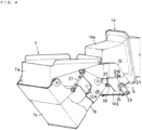
- Fig. 4 is a perspective view from one lateral side of structural details for attachment of the weighing hopper 7. This drawing shows the structure of Fig. 2 from which the working link 23 and the connection link 24 have been removed.
- Fig. 5 is a perspective view from another lateral side of the structural details for attachment of the weighing hopper 7.
- Fig. 6 is a perspective view from one lateral side of the driving unit 14 mounted for the weighing hopper 7.
- Fig. 7 is a perspective view from another lateral side of the driving unit 14 mounted for the weighing hopper 7.
- a boss portion 28 As illustrated in Fig. 6 , a boss portion 28; an engaging protrusion that pivotally and rotatably supports the driving arm 25, is securely screwed into one lateral surface of the lower case 14b of the driving unit 14.
- This boss portion 28 has, in a part thereof, a circular portion 28a.
- This circular portion 28a is engageable with the hook portion 27 of one of the attachment brackets 22 without any wobble.
- the boss portion 28, which pivotally and rotatably support the driving arm 25 that drives the gates 7b and 7c to open and close, is thus used as an engaging protrusion that supportably catches the attachment bracket 22. This may favorably reduce the number of components, possibly leading to cost reduction, as compared with a dedicated protrusion for engagement being prepared apart from the boss portion 28.
- a boss portion 29 As illustrated in Fig. 7 , a boss portion 29; an engaging protrusion, is screwed into the other lateral surface of the lower case 14b.
- This boss portion 29 has, in a part thereof, a circular portion 29a.
- This circular portion 29a is engageable with the hook portion 27 of the other attachment bracket 22 without any wobble.
- Support pins 30 are respectively screwed securely into the lateral surfaces of the lower case 14b at positions on the outer side than the boss portions 28 and 29, i.e., at positions closer to the hopper.
- Fig. 8 is a lateral view from one side of how the weighing hopper 7 is attachable.
- Fig. 9 is a lateral view from another side of how the weighing hopper 7 is attachable.
- the weighing hopper 7 is moved, from outward and upward, toward the driving unit 14 mounted to the outer circumference of the center base body 1, and the hook portions 27 of the attachment brackets 22 on both sides are engaged with the boss portions 28 and 29; engaging protrusions, disposed on the lateral surfaces of the lower case 14b. Then, contact portions 31 of the attachment brackets 22 at lower edges thereof are brought into contact with the support pins 30 of the lower case 14b.
- the contact portions 31 each have an angled part. These angled parts of the contact portions 31 contact the support pins 30 in two directions; upper direction and inner direction (on the driving-unit side). As a result, the weighing hopper 7 is laterally positioned in a predetermined direction and angle in which forward, backward and downward movements are preventable. The weighing hopper 7 thus positioned is then attached to the lower case 14b.
- the gates 7b and 7c may be allowed to open and close by having the working link 23 engaged with the driving pin 21 at the same time when the hopper is attached to the driving unit.
- the weighing hopper 7 may be easily removed from the scale when the hook portions 27 are pulled off the engaging protrusions 28 and 29, with the attached weighing hopper 7 being lifted upward and outward.
- the driving unit 14 may only need to have the following elements on its lateral surfaces for attachment of the weighing hopper 7; the boss portions 28 and 29 supportably engageable with the paired attachment brackets 22 of the weighing hopper 7, and the support pins 30 that supportably contacts the contact portions 31 of the attachment brackets 22. Therefore, front surfaces of the upper and lower cases 14a and 14b of the driving unit 14, i.e., the faces facing the body 7a of the weighing hopper 7, are unoccupied, flat surfaces, as illustrated in Figs. 6 and 7 .
- the problem with the known art described in patent literature 1 is a step and a gap inevitably formed when the flat base portion of the hanger is attached to the front surface of the driving unit with bolts. This embodiment, on the other hand, may certainly avoid such a problem.
- the elements required of the driving unit 14 for hopper attachment may be the boss portions 28 and 29 and the support pins 30 alone, which may eliminate the need to prepare a pair of upper and lower hangers as described in patent literature 1.
- the paired attachment brackets 22 may be processed in part into different shapes to form the hook portions 27 and the contact portions 31.
- a pair of upper and lower support bars disposed on the rear surface of the hopper may no longer be necessary. This may lead to cost reduction and weight reduction of the whole hopper.
- the scope of this invention may include the following modes.
Landscapes
- Physics & Mathematics (AREA)
- General Physics & Mathematics (AREA)
- Engineering & Computer Science (AREA)
- Mechanical Engineering (AREA)
- Filling Or Emptying Of Bunkers, Hoppers, And Tanks (AREA)
- Weight Measurement For Supplying Or Discharging Of Specified Amounts Of Material (AREA)
Applications Claiming Priority (1)
| Application Number | Priority Date | Filing Date | Title |
|---|---|---|---|
| PCT/JP2020/016897 WO2021210167A1 (ja) | 2020-04-17 | 2020-04-17 | ホッパ取付け構造及びそれを備えた計量装置 |
Publications (3)
| Publication Number | Publication Date |
|---|---|
| EP4137785A1 EP4137785A1 (en) | 2023-02-22 |
| EP4137785A4 EP4137785A4 (en) | 2024-01-03 |
| EP4137785B1 true EP4137785B1 (en) | 2024-07-24 |
Family
ID=78084302
Family Applications (1)
| Application Number | Title | Priority Date | Filing Date |
|---|---|---|---|
| EP20931427.7A Active EP4137785B1 (en) | 2020-04-17 | 2020-04-17 | Hopper attachment structure and weighing device comprising same |
Country Status (5)
| Country | Link |
|---|---|
| US (1) | US12429370B2 (https=) |
| EP (1) | EP4137785B1 (https=) |
| JP (1) | JP7403934B2 (https=) |
| CN (1) | CN115315616B (https=) |
| WO (1) | WO2021210167A1 (https=) |
Families Citing this family (6)
| Publication number | Priority date | Publication date | Assignee | Title |
|---|---|---|---|---|
| US12228446B2 (en) * | 2020-02-07 | 2025-02-18 | Yamato Scale Co., Ltd. | Combination scale |
| IT202200008882A1 (it) * | 2022-05-03 | 2023-11-03 | Ilapak Italia S P A | Kit di componenti per comporre una tramoggia intercambiabile per la dosatura/pesatura di prodotti in una apparecchiatura di pesatura combinata. |
| WO2024218936A1 (ja) * | 2023-04-20 | 2024-10-24 | 大和製衡株式会社 | 組合せ計量装置の防水構造 |
| JP7812190B2 (ja) * | 2023-04-20 | 2026-02-09 | 大和製衡株式会社 | 組合せ計量装置の防水構造 |
| EP4700339A1 (en) * | 2023-04-20 | 2026-02-25 | Yamato Scale Co., Ltd. | Waterproof structure of combination weighing device |
| JP2025062491A (ja) * | 2023-10-02 | 2025-04-14 | 株式会社イシダ | 物品滞留装置 |
Family Cites Families (18)
| Publication number | Priority date | Publication date | Assignee | Title |
|---|---|---|---|---|
| US4545446A (en) * | 1983-05-11 | 1985-10-08 | Kabushiki Kaisha Ishida Koki Seisakusho | Hopper in combinatorial weighing apparatus |
| GB8705451D0 (en) * | 1987-03-09 | 1987-04-15 | Driver Southall | Combinational weighing systems |
| JPH059346Y2 (https=) * | 1987-12-03 | 1993-03-08 | ||
| US5379923A (en) | 1992-06-17 | 1995-01-10 | Eagle Packaging Corp. | Hopper for a weighing machine |
| US5611437A (en) * | 1995-04-19 | 1997-03-18 | Sea-Chang Ting | Automatically openable and closable hopper set for a fruit weighing and sorting machine |
| GB9521252D0 (en) * | 1995-10-17 | 1995-12-20 | Bishopbarn Ltd | Improvements in and relating to weighing machines |
| JP2001148319A (ja) | 1999-11-22 | 2001-05-29 | Matsushita Electric Ind Co Ltd | フライバックトランス |
| JP4659167B2 (ja) * | 1999-11-24 | 2011-03-30 | 正俊 今中 | ホッパ装置 |
| JP2002168681A (ja) * | 2000-12-05 | 2002-06-14 | Anritsu Corp | 組合せ計量装置 |
| JP3819330B2 (ja) | 2002-06-26 | 2006-09-06 | 株式会社イシダ | ホッパ及びそれを備えた計量装置 |
| JP5295873B2 (ja) * | 2009-06-05 | 2013-09-18 | 株式会社イシダ | 組合せ計量装置 |
| CN106363348A (zh) * | 2010-10-29 | 2017-02-01 | 株式会社威工 | 容器的制造方法 |
| JP5731273B2 (ja) * | 2011-05-11 | 2015-06-10 | 株式会社イシダ | 組合せ計量機のホッパアセンブリ |
| CN204301843U (zh) * | 2014-12-12 | 2015-04-29 | 佛山市顺德区安本智能机器有限公司 | 一种用于组合秤的料斗 |
| JP6465356B2 (ja) * | 2015-07-02 | 2019-02-06 | 大和製衡株式会社 | ホッパ及びこれを備えた組合せ秤 |
| JP6707759B2 (ja) * | 2016-09-20 | 2020-06-10 | 株式会社イシダ | ホッパ及び組合せ計量装置 |
| CN108482894A (zh) * | 2018-05-22 | 2018-09-04 | 广东安本智能机器有限公司 | 一种用于组合秤的料斗机构 |
| JP3227867U (ja) | 2020-06-12 | 2020-09-24 | 株式会社竹本組 | 抜型枠保持用器具 |
-
2020
- 2020-04-17 JP JP2022515168A patent/JP7403934B2/ja active Active
- 2020-04-17 EP EP20931427.7A patent/EP4137785B1/en active Active
- 2020-04-17 CN CN202080099073.4A patent/CN115315616B/zh active Active
- 2020-04-17 US US17/916,381 patent/US12429370B2/en active Active
- 2020-04-17 WO PCT/JP2020/016897 patent/WO2021210167A1/ja not_active Ceased
Also Published As
| Publication number | Publication date |
|---|---|
| JP7403934B2 (ja) | 2023-12-25 |
| CN115315616B (zh) | 2025-09-05 |
| US12429370B2 (en) | 2025-09-30 |
| CN115315616A (zh) | 2022-11-08 |
| EP4137785A4 (en) | 2024-01-03 |
| EP4137785A1 (en) | 2023-02-22 |
| WO2021210167A1 (ja) | 2021-10-21 |
| JPWO2021210167A1 (https=) | 2021-10-21 |
| US20230152143A1 (en) | 2023-05-18 |
Similar Documents
| Publication | Publication Date | Title |
|---|---|---|
| EP4137785B1 (en) | Hopper attachment structure and weighing device comprising same | |
| JP6465356B2 (ja) | ホッパ及びこれを備えた組合せ秤 | |
| US7790990B2 (en) | Combination weigher with peripheral annular recycling table | |
| CN112204361B (zh) | 组合计量装置 | |
| WO2016067883A1 (ja) | 物品処理装置 | |
| EP3875923B1 (en) | Supporting body and article retaining device | |
| US11125604B2 (en) | Combination weighing device including a movable and detachable discharge chute | |
| JP5844041B2 (ja) | 集合シュート支持構造および組合せ計量装置 | |
| JP6242086B2 (ja) | 組合せ秤 | |
| JP6279355B2 (ja) | 組合せ秤 | |
| CN111693129B (zh) | 组合计量装置及组合计量装置用台架 | |
| JP2016020248A (ja) | ホッパ及びこれを備える組合せ秤 | |
| JP6396983B2 (ja) | 組合せ計量装置 | |
| JP6305836B2 (ja) | 物品規制装置及びこれを備える組合せ秤 | |
| JP2019172318A (ja) | 物品供給装置 | |
| JP5490607B2 (ja) | 組合せ秤 | |
| JP7086814B2 (ja) | 組合せ秤の直進フィーダ | |
| JP3200044U (ja) | ホッパ及びこれを備えた組合せ秤 | |
| JP2014215236A (ja) | 集合ホッパ及びこれを備えた組合せ秤 | |
| JP7537854B2 (ja) | ホッパ及び組合せ秤 | |
| JP2010096651A (ja) | 組合せ秤 | |
| EP4700340A1 (en) | Waterproof structure of combination weighing apparatus | |
| EP0307188A2 (en) | Collecting weighed articles | |
| JP2006170644A (ja) | 組合せ計量装置 | |
| JP2023089537A (ja) | 組合せ秤 |
Legal Events
| Date | Code | Title | Description |
|---|---|---|---|
| STAA | Information on the status of an ep patent application or granted ep patent |
Free format text: STATUS: THE INTERNATIONAL PUBLICATION HAS BEEN MADE |
|
| PUAI | Public reference made under article 153(3) epc to a published international application that has entered the european phase |
Free format text: ORIGINAL CODE: 0009012 |
|
| STAA | Information on the status of an ep patent application or granted ep patent |
Free format text: STATUS: REQUEST FOR EXAMINATION WAS MADE |
|
| 17P | Request for examination filed |
Effective date: 20221109 |
|
| AK | Designated contracting states |
Kind code of ref document: A1 Designated state(s): AL AT BE BG CH CY CZ DE DK EE ES FI FR GB GR HR HU IE IS IT LI LT LU LV MC MK MT NL NO PL PT RO RS SE SI SK SM TR |
|
| DAV | Request for validation of the european patent (deleted) | ||
| DAX | Request for extension of the european patent (deleted) | ||
| REG | Reference to a national code |
Ref country code: DE Free format text: PREVIOUS MAIN CLASS: G01G0019387000 Ref country code: DE Ref legal event code: R079 Ref document number: 602020034676 Country of ref document: DE Free format text: PREVIOUS MAIN CLASS: G01G0019387000 Ipc: G01G0019393000 |
|
| A4 | Supplementary search report drawn up and despatched |
Effective date: 20231130 |
|
| RIC1 | Information provided on ipc code assigned before grant |
Ipc: G01G 19/393 20060101AFI20231124BHEP |
|
| GRAP | Despatch of communication of intention to grant a patent |
Free format text: ORIGINAL CODE: EPIDOSNIGR1 |
|
| STAA | Information on the status of an ep patent application or granted ep patent |
Free format text: STATUS: GRANT OF PATENT IS INTENDED |
|
| INTG | Intention to grant announced |
Effective date: 20240409 |
|
| GRAS | Grant fee paid |
Free format text: ORIGINAL CODE: EPIDOSNIGR3 |
|
| GRAA | (expected) grant |
Free format text: ORIGINAL CODE: 0009210 |
|
| STAA | Information on the status of an ep patent application or granted ep patent |
Free format text: STATUS: THE PATENT HAS BEEN GRANTED |
|
| AK | Designated contracting states |
Kind code of ref document: B1 Designated state(s): AL AT BE BG CH CY CZ DE DK EE ES FI FR GB GR HR HU IE IS IT LI LT LU LV MC MK MT NL NO PL PT RO RS SE SI SK SM TR |
|
| REG | Reference to a national code |
Ref country code: GB Ref legal event code: FG4D |
|
| REG | Reference to a national code |
Ref country code: CH Ref legal event code: EP |
|
| REG | Reference to a national code |
Ref country code: IE Ref legal event code: FG4D Ref country code: DE Ref legal event code: R096 Ref document number: 602020034676 Country of ref document: DE |
|
| REG | Reference to a national code |
Ref country code: LT Ref legal event code: MG9D |
|
| REG | Reference to a national code |
Ref country code: NL Ref legal event code: MP Effective date: 20240724 |
|
| PG25 | Lapsed in a contracting state [announced via postgrant information from national office to epo] |
Ref country code: PT Free format text: LAPSE BECAUSE OF FAILURE TO SUBMIT A TRANSLATION OF THE DESCRIPTION OR TO PAY THE FEE WITHIN THE PRESCRIBED TIME-LIMIT Effective date: 20241125 |
|
| REG | Reference to a national code |
Ref country code: AT Ref legal event code: MK05 Ref document number: 1706692 Country of ref document: AT Kind code of ref document: T Effective date: 20240724 |
|
| PG25 | Lapsed in a contracting state [announced via postgrant information from national office to epo] |
Ref country code: NL Free format text: LAPSE BECAUSE OF FAILURE TO SUBMIT A TRANSLATION OF THE DESCRIPTION OR TO PAY THE FEE WITHIN THE PRESCRIBED TIME-LIMIT Effective date: 20240724 |
|
| PG25 | Lapsed in a contracting state [announced via postgrant information from national office to epo] |
Ref country code: PT Free format text: LAPSE BECAUSE OF FAILURE TO SUBMIT A TRANSLATION OF THE DESCRIPTION OR TO PAY THE FEE WITHIN THE PRESCRIBED TIME-LIMIT Effective date: 20241125 Ref country code: NL Free format text: LAPSE BECAUSE OF FAILURE TO SUBMIT A TRANSLATION OF THE DESCRIPTION OR TO PAY THE FEE WITHIN THE PRESCRIBED TIME-LIMIT Effective date: 20240724 |
|
| PG25 | Lapsed in a contracting state [announced via postgrant information from national office to epo] |
Ref country code: NO Free format text: LAPSE BECAUSE OF FAILURE TO SUBMIT A TRANSLATION OF THE DESCRIPTION OR TO PAY THE FEE WITHIN THE PRESCRIBED TIME-LIMIT Effective date: 20241024 |
|
| PG25 | Lapsed in a contracting state [announced via postgrant information from national office to epo] |
Ref country code: FI Free format text: LAPSE BECAUSE OF FAILURE TO SUBMIT A TRANSLATION OF THE DESCRIPTION OR TO PAY THE FEE WITHIN THE PRESCRIBED TIME-LIMIT Effective date: 20240724 Ref country code: PL Free format text: LAPSE BECAUSE OF FAILURE TO SUBMIT A TRANSLATION OF THE DESCRIPTION OR TO PAY THE FEE WITHIN THE PRESCRIBED TIME-LIMIT Effective date: 20240724 Ref country code: GR Free format text: LAPSE BECAUSE OF FAILURE TO SUBMIT A TRANSLATION OF THE DESCRIPTION OR TO PAY THE FEE WITHIN THE PRESCRIBED TIME-LIMIT Effective date: 20241025 |
|
| PG25 | Lapsed in a contracting state [announced via postgrant information from national office to epo] |
Ref country code: BG Free format text: LAPSE BECAUSE OF FAILURE TO SUBMIT A TRANSLATION OF THE DESCRIPTION OR TO PAY THE FEE WITHIN THE PRESCRIBED TIME-LIMIT Effective date: 20240724 |
|
| PG25 | Lapsed in a contracting state [announced via postgrant information from national office to epo] |
Ref country code: LV Free format text: LAPSE BECAUSE OF FAILURE TO SUBMIT A TRANSLATION OF THE DESCRIPTION OR TO PAY THE FEE WITHIN THE PRESCRIBED TIME-LIMIT Effective date: 20240724 |
|
| PG25 | Lapsed in a contracting state [announced via postgrant information from national office to epo] |
Ref country code: AT Free format text: LAPSE BECAUSE OF FAILURE TO SUBMIT A TRANSLATION OF THE DESCRIPTION OR TO PAY THE FEE WITHIN THE PRESCRIBED TIME-LIMIT Effective date: 20240724 Ref country code: IS Free format text: LAPSE BECAUSE OF FAILURE TO SUBMIT A TRANSLATION OF THE DESCRIPTION OR TO PAY THE FEE WITHIN THE PRESCRIBED TIME-LIMIT Effective date: 20241124 |
|
| PG25 | Lapsed in a contracting state [announced via postgrant information from national office to epo] |
Ref country code: HR Free format text: LAPSE BECAUSE OF FAILURE TO SUBMIT A TRANSLATION OF THE DESCRIPTION OR TO PAY THE FEE WITHIN THE PRESCRIBED TIME-LIMIT Effective date: 20240724 |
|
| PG25 | Lapsed in a contracting state [announced via postgrant information from national office to epo] |
Ref country code: RS Free format text: LAPSE BECAUSE OF FAILURE TO SUBMIT A TRANSLATION OF THE DESCRIPTION OR TO PAY THE FEE WITHIN THE PRESCRIBED TIME-LIMIT Effective date: 20241024 Ref country code: ES Free format text: LAPSE BECAUSE OF FAILURE TO SUBMIT A TRANSLATION OF THE DESCRIPTION OR TO PAY THE FEE WITHIN THE PRESCRIBED TIME-LIMIT Effective date: 20240724 |
|
| PG25 | Lapsed in a contracting state [announced via postgrant information from national office to epo] |
Ref country code: RS Free format text: LAPSE BECAUSE OF FAILURE TO SUBMIT A TRANSLATION OF THE DESCRIPTION OR TO PAY THE FEE WITHIN THE PRESCRIBED TIME-LIMIT Effective date: 20241024 Ref country code: PL Free format text: LAPSE BECAUSE OF FAILURE TO SUBMIT A TRANSLATION OF THE DESCRIPTION OR TO PAY THE FEE WITHIN THE PRESCRIBED TIME-LIMIT Effective date: 20240724 Ref country code: NO Free format text: LAPSE BECAUSE OF FAILURE TO SUBMIT A TRANSLATION OF THE DESCRIPTION OR TO PAY THE FEE WITHIN THE PRESCRIBED TIME-LIMIT Effective date: 20241024 Ref country code: LV Free format text: LAPSE BECAUSE OF FAILURE TO SUBMIT A TRANSLATION OF THE DESCRIPTION OR TO PAY THE FEE WITHIN THE PRESCRIBED TIME-LIMIT Effective date: 20240724 Ref country code: IS Free format text: LAPSE BECAUSE OF FAILURE TO SUBMIT A TRANSLATION OF THE DESCRIPTION OR TO PAY THE FEE WITHIN THE PRESCRIBED TIME-LIMIT Effective date: 20241124 Ref country code: HR Free format text: LAPSE BECAUSE OF FAILURE TO SUBMIT A TRANSLATION OF THE DESCRIPTION OR TO PAY THE FEE WITHIN THE PRESCRIBED TIME-LIMIT Effective date: 20240724 Ref country code: GR Free format text: LAPSE BECAUSE OF FAILURE TO SUBMIT A TRANSLATION OF THE DESCRIPTION OR TO PAY THE FEE WITHIN THE PRESCRIBED TIME-LIMIT Effective date: 20241025 Ref country code: FI Free format text: LAPSE BECAUSE OF FAILURE TO SUBMIT A TRANSLATION OF THE DESCRIPTION OR TO PAY THE FEE WITHIN THE PRESCRIBED TIME-LIMIT Effective date: 20240724 Ref country code: ES Free format text: LAPSE BECAUSE OF FAILURE TO SUBMIT A TRANSLATION OF THE DESCRIPTION OR TO PAY THE FEE WITHIN THE PRESCRIBED TIME-LIMIT Effective date: 20240724 Ref country code: BG Free format text: LAPSE BECAUSE OF FAILURE TO SUBMIT A TRANSLATION OF THE DESCRIPTION OR TO PAY THE FEE WITHIN THE PRESCRIBED TIME-LIMIT Effective date: 20240724 Ref country code: AT Free format text: LAPSE BECAUSE OF FAILURE TO SUBMIT A TRANSLATION OF THE DESCRIPTION OR TO PAY THE FEE WITHIN THE PRESCRIBED TIME-LIMIT Effective date: 20240724 |
|
| PG25 | Lapsed in a contracting state [announced via postgrant information from national office to epo] |
Ref country code: SM Free format text: LAPSE BECAUSE OF FAILURE TO SUBMIT A TRANSLATION OF THE DESCRIPTION OR TO PAY THE FEE WITHIN THE PRESCRIBED TIME-LIMIT Effective date: 20240724 Ref country code: DK Free format text: LAPSE BECAUSE OF FAILURE TO SUBMIT A TRANSLATION OF THE DESCRIPTION OR TO PAY THE FEE WITHIN THE PRESCRIBED TIME-LIMIT Effective date: 20240724 Ref country code: RO Free format text: LAPSE BECAUSE OF FAILURE TO SUBMIT A TRANSLATION OF THE DESCRIPTION OR TO PAY THE FEE WITHIN THE PRESCRIBED TIME-LIMIT Effective date: 20240724 |
|
| PG25 | Lapsed in a contracting state [announced via postgrant information from national office to epo] |
Ref country code: EE Free format text: LAPSE BECAUSE OF FAILURE TO SUBMIT A TRANSLATION OF THE DESCRIPTION OR TO PAY THE FEE WITHIN THE PRESCRIBED TIME-LIMIT Effective date: 20240724 |
|
| PG25 | Lapsed in a contracting state [announced via postgrant information from national office to epo] |
Ref country code: CZ Free format text: LAPSE BECAUSE OF FAILURE TO SUBMIT A TRANSLATION OF THE DESCRIPTION OR TO PAY THE FEE WITHIN THE PRESCRIBED TIME-LIMIT Effective date: 20240724 |
|
| REG | Reference to a national code |
Ref country code: DE Ref legal event code: R097 Ref document number: 602020034676 Country of ref document: DE |
|
| PG25 | Lapsed in a contracting state [announced via postgrant information from national office to epo] |
Ref country code: SK Free format text: LAPSE BECAUSE OF FAILURE TO SUBMIT A TRANSLATION OF THE DESCRIPTION OR TO PAY THE FEE WITHIN THE PRESCRIBED TIME-LIMIT Effective date: 20240724 |
|
| PLBE | No opposition filed within time limit |
Free format text: ORIGINAL CODE: 0009261 |
|
| STAA | Information on the status of an ep patent application or granted ep patent |
Free format text: STATUS: NO OPPOSITION FILED WITHIN TIME LIMIT |
|
| 26N | No opposition filed |
Effective date: 20250425 |
|
| PGFP | Annual fee paid to national office [announced via postgrant information from national office to epo] |
Ref country code: DE Payment date: 20250305 Year of fee payment: 6 |
|
| PG25 | Lapsed in a contracting state [announced via postgrant information from national office to epo] |
Ref country code: SE Free format text: LAPSE BECAUSE OF FAILURE TO SUBMIT A TRANSLATION OF THE DESCRIPTION OR TO PAY THE FEE WITHIN THE PRESCRIBED TIME-LIMIT Effective date: 20240724 |
|
| REG | Reference to a national code |
Ref country code: CH Ref legal event code: H13 Free format text: ST27 STATUS EVENT CODE: U-0-0-H10-H13 (AS PROVIDED BY THE NATIONAL OFFICE) Effective date: 20251125 |
|
| PG25 | Lapsed in a contracting state [announced via postgrant information from national office to epo] |
Ref country code: LU Free format text: LAPSE BECAUSE OF NON-PAYMENT OF DUE FEES Effective date: 20250417 |
|
| PG25 | Lapsed in a contracting state [announced via postgrant information from national office to epo] |
Ref country code: MC Free format text: LAPSE BECAUSE OF FAILURE TO SUBMIT A TRANSLATION OF THE DESCRIPTION OR TO PAY THE FEE WITHIN THE PRESCRIBED TIME-LIMIT Effective date: 20240724 |
|
| REG | Reference to a national code |
Ref country code: BE Ref legal event code: MM Effective date: 20250430 |
|
| PG25 | Lapsed in a contracting state [announced via postgrant information from national office to epo] |
Ref country code: BE Free format text: LAPSE BECAUSE OF NON-PAYMENT OF DUE FEES Effective date: 20250430 |
|
| PG25 | Lapsed in a contracting state [announced via postgrant information from national office to epo] |
Ref country code: CH Free format text: LAPSE BECAUSE OF NON-PAYMENT OF DUE FEES Effective date: 20250430 |
|
| PGFP | Annual fee paid to national office [announced via postgrant information from national office to epo] |
Ref country code: GB Payment date: 20260313 Year of fee payment: 7 |
|
| PG25 | Lapsed in a contracting state [announced via postgrant information from national office to epo] |
Ref country code: IE Free format text: LAPSE BECAUSE OF NON-PAYMENT OF DUE FEES Effective date: 20250417 |
|
| PGFP | Annual fee paid to national office [announced via postgrant information from national office to epo] |
Ref country code: IT Payment date: 20260320 Year of fee payment: 7 |
|
| PGFP | Annual fee paid to national office [announced via postgrant information from national office to epo] |
Ref country code: FR Payment date: 20260309 Year of fee payment: 7 |