EP4137029B1 - Elektrisches gerät, insbesondere sauggerät oder werkzeugmaschine - Google Patents
Elektrisches gerät, insbesondere sauggerät oder werkzeugmaschine Download PDFInfo
- Publication number
- EP4137029B1 EP4137029B1 EP22186384.8A EP22186384A EP4137029B1 EP 4137029 B1 EP4137029 B1 EP 4137029B1 EP 22186384 A EP22186384 A EP 22186384A EP 4137029 B1 EP4137029 B1 EP 4137029B1
- Authority
- EP
- European Patent Office
- Prior art keywords
- energy storage
- suction
- housing
- receptacle
- electrical device
- Prior art date
- Legal status (The legal status is an assumption and is not a legal conclusion. Google has not performed a legal analysis and makes no representation as to the accuracy of the status listed.)
- Active
Links
Images


Classifications
-
- A—HUMAN NECESSITIES
- A47—FURNITURE; DOMESTIC ARTICLES OR APPLIANCES; COFFEE MILLS; SPICE MILLS; SUCTION CLEANERS IN GENERAL
- A47L—DOMESTIC WASHING OR CLEANING; SUCTION CLEANERS IN GENERAL
- A47L9/00—Details or accessories of suction cleaners, e.g. mechanical means for controlling the suction or for effecting pulsating action; Storing devices specially adapted to suction cleaners or parts thereof; Carrying-vehicles specially adapted for suction cleaners
- A47L9/28—Installation of the electric equipment, e.g. adaptation or attachment to the suction cleaner; Controlling suction cleaners by electric means
- A47L9/2868—Arrangements for power supply of vacuum cleaners or the accessories thereof
- A47L9/2884—Details of arrangements of batteries or their installation
-
- A—HUMAN NECESSITIES
- A47—FURNITURE; DOMESTIC ARTICLES OR APPLIANCES; COFFEE MILLS; SPICE MILLS; SUCTION CLEANERS IN GENERAL
- A47L—DOMESTIC WASHING OR CLEANING; SUCTION CLEANERS IN GENERAL
- A47L11/00—Machines for cleaning floors, carpets, furniture, walls, or wall coverings
- A47L11/40—Parts or details of machines not provided for in groups A47L11/02 - A47L11/38, or not restricted to one of these groups, e.g. handles, arrangements of switches, skirts, buffers, levers
- A47L11/4002—Installations of electric equipment
- A47L11/4005—Arrangements of batteries or cells; Electric power supply arrangements
-
- A—HUMAN NECESSITIES
- A47—FURNITURE; DOMESTIC ARTICLES OR APPLIANCES; COFFEE MILLS; SPICE MILLS; SUCTION CLEANERS IN GENERAL
- A47L—DOMESTIC WASHING OR CLEANING; SUCTION CLEANERS IN GENERAL
- A47L9/00—Details or accessories of suction cleaners, e.g. mechanical means for controlling the suction or for effecting pulsating action; Storing devices specially adapted to suction cleaners or parts thereof; Carrying-vehicles specially adapted for suction cleaners
- A47L9/22—Mountings for motor fan assemblies
-
- B—PERFORMING OPERATIONS; TRANSPORTING
- B25—HAND TOOLS; PORTABLE POWER-DRIVEN TOOLS; MANIPULATORS
- B25F—COMBINATION OR MULTI-PURPOSE TOOLS NOT OTHERWISE PROVIDED FOR; DETAILS OR COMPONENTS OF PORTABLE POWER-DRIVEN TOOLS NOT PARTICULARLY RELATED TO THE OPERATIONS PERFORMED AND NOT OTHERWISE PROVIDED FOR
- B25F5/00—Details or components of portable power-driven tools not particularly related to the operations performed and not otherwise provided for
- B25F5/02—Construction of casings, bodies or handles
-
- B—PERFORMING OPERATIONS; TRANSPORTING
- B25—HAND TOOLS; PORTABLE POWER-DRIVEN TOOLS; MANIPULATORS
- B25H—WORKSHOP EQUIPMENT, e.g. FOR MARKING-OUT WORK; STORAGE MEANS FOR WORKSHOPS
- B25H3/00—Storage means or arrangements for workshops facilitating access to, or handling of, work tools or instruments
- B25H3/02—Boxes
-
- H—ELECTRICITY
- H02—GENERATION; CONVERSION OR DISTRIBUTION OF ELECTRIC POWER
- H02J—CIRCUIT ARRANGEMENTS OR SYSTEMS FOR SUPPLYING OR DISTRIBUTING ELECTRIC POWER; SYSTEMS FOR STORING ELECTRIC ENERGY
- H02J7/00—Circuit arrangements for charging or depolarising batteries or for supplying loads from batteries
- H02J7/0013—Circuit arrangements for charging or depolarising batteries or for supplying loads from batteries acting upon several batteries simultaneously or sequentially
-
- H—ELECTRICITY
- H02—GENERATION; CONVERSION OR DISTRIBUTION OF ELECTRIC POWER
- H02J—CIRCUIT ARRANGEMENTS OR SYSTEMS FOR SUPPLYING OR DISTRIBUTING ELECTRIC POWER; SYSTEMS FOR STORING ELECTRIC ENERGY
- H02J7/00—Circuit arrangements for charging or depolarising batteries or for supplying loads from batteries
- H02J7/0042—Circuit arrangements for charging or depolarising batteries or for supplying loads from batteries characterised by the mechanical construction
- H02J7/0045—Circuit arrangements for charging or depolarising batteries or for supplying loads from batteries characterised by the mechanical construction concerning the insertion or the connection of the batteries
Definitions
- the invention relates to an electrical device, for example in the form of a suction device or a machine tool and/or as a mobile electrical device, with a housing in which at least one electrical consumer, in particular a drive motor, is arranged, the electrical device being used to supply electrical power to the electrical consumer, in particular the drive motor, has a power supply device with an energy storage receptacle, in the interior of which at least two device interfaces are arranged for the detachable connection of an energy storage interface of an electrical energy storage device, in particular a battery pack.
- the energy storage devices are, for example, so-called battery packs that can be detachably connected to the electrical device, for example the suction device or the machine tool, in particular a hand-held machine tool.
- the electrical device for example the suction device or the machine tool, in particular a hand-held machine tool.
- electrical devices of this type in order to increase mobility and/or electrical power, it is necessary for several, for example two, such energy storage devices to be available for energy output at the same time.
- the electrical power density of rechargeable energy storage devices is still so low that they are relatively voluminous.
- the energy storage receptacle must therefore have a large storage volume so that the energy storage can still be grasped by an operator in order to remove them from the energy storage receptacle, for example.
- Examples of such electrical devices are from the DE 10 2010 043577 A1 , DE 10 2005 007923 A1 and DE 20 2020 105705 U1 known.
- an electrical device in particular a suction device or a machine tool, of the type mentioned at the outset, provision is made for the device interfaces to be arranged on opposite side walls of the energy storage receptacle, so that the energy storage devices are mounted with bottom walls facing one another Device interfaces can be arranged.
- the electrical device is advantageously a mobile electrical device.
- the invention can also be easily applied to stationary electrical devices.
- the electrical energy storage contains, for example, several battery cells.
- the battery cells are arranged, for example, in a row arrangement next to one another in a housing of the respective energy storage device.
- the battery cells are, for example, connected in series and/or parallel to one another.
- the electrical energy stores are preferably rechargeable electrical energy stores. To charge a respective energy storage device, it can be removed from the energy storage holder.
- the energy storage can, for example, be connectable with its energy storage interface to a charger for electrical charging.
- the battery cells have, for example, cylindrical housings or a cylindrical shape.
- the battery cells are arranged, for example, in one or more layers within an energy storage housing.
- the energy storage interfaces of the preferably mobile electrical device are connected in series or parallel to one another, for example, so that, for example, a supply voltage that the energy storage provides is added in a series connection. If the energy storage interfaces are connected in parallel to one another, the available current is higher, for example.
- Further energy storage devices can easily be arranged at the energy storage interface.
- the further energy storage devices can also be held in or on the energy storage interface with bottom walls facing one another.
- the stationary or mobile electrical device for example, to have energy storage interfaces that are not arranged on opposite side walls of the energy storage receptacle.
- the electrical device can also have at least one further energy storage receptacle, in which, for example, energy storage interfaces are provided which are arranged on opposite sides of a retaining wall of the energy storage receptacle.
- the at least one energy storage receptacle can also have only a single energy storage interface for connecting a single energy storage device.
- the at least one further energy storage recording channel can be designed as a receiving pocket, receiving compartment or the like.
- the electrical device is a mobile electrical device, it retains its mobility, so to speak, because it does not rely on a network interface.
- the electrical consumer is preferably an electric drive motor.
- the electrical device can also include, for example, a charging interface for charging another electrical energy storage device.
- the housing has a housing interior in which the charging interface for charging the further electrical energy storage is arranged.
- the machine tool is, for example, a sawing machine, milling machine or the like.
- the energy storage receptacle has an insertion opening through which the energy storage can be inserted into the energy storage receptacle.
- An extension of the insertion opening is preferably suitable for inserting an energy storage device into the energy storage receptacle or removing it from the energy storage receptacle, while the other energy storage device is arranged in the energy storage receptacle. It is advantageous if the insertion opening is arranged on an outer wall of the housing.
- the energy storage receptacle has an opening on a side opposite the insertion opening, so that a type of passage is present, for example.
- a passage or passage opening is particularly suitable for cooling the energy storage device arranged in the energy storage receptacle.
- the energy storage receptacle is preferably designed as a pocket or a compartment on an outer wall of the housing.
- the energy storage receptacle has such a depth that the energy storage does not or only extends a maximum of 10% of its length in front of the energy storage receptacle and / or an outer contour of the housing protrude when the energy storage is included in the energy storage receptacle. It is therefore advantageous if the energy storage device or energy storage devices can, so to speak, engage completely in the energy storage holder and/or do not protrude in front of a wall, in particular not in front of an outer wall, of the housing on which the energy storage holder is arranged.
- the device interfaces have longitudinal guide contours for guiding engagement of longitudinal guide contours of the energy storage interfaces along plug-in axles.
- the longitudinal guide contours include, for example, guide grooves and guide projections, each of which extends along the plug-in axes.
- the quick-release axles can be parallel to each other. However, it is also possible for the quick-release axles to be arranged at an angle to one another, preferably at a small angle of a maximum of 30°, in particular a maximum of 20°, particularly preferably a maximum of 10° or even more preferably a maximum of 5°.
- device interfaces also have rear gripping contours which interact with counter-rear gripping contours of the energy storage interfaces, so that the energy storage devices, when they are arranged on the device interfaces, are held in a form-fitting manner on the device interfaces transversely to their respective plug-in axes .
- the rear gripping contours include holding projections which extend transversely to the respective plug-in axle and which can be brought into or out of engagement with one another by a sliding actuation parallel to the plug-in axle.
- the device interfaces include locking devices for locking locking devices of the energy storage interfaces.
- the locking devices include, for example, one or more locking receptacles.
- the energy storage interfaces have locking devices that are complementary to the locking devices of the device interfaces, for example at least one locking projection.
- the device interfaces of the electrical device preferably include contact arrangements for establishing electrical connections to contact arrangements of the energy storage interfaces of the energy storage devices.
- These contact arrangements of the device interfaces and/or the energy storage interfaces include, for example, energy supply contacts and/or data contacts.
- the contact arrangements include, for example, spring contacts, contact tongues or the like.
- the contact arrangements of the energy storage interfaces and the device interfaces come into electrical contact with one another when the energy storage devices are connected to the device interfaces.
- the energy supply contacts are used to supply electrical energy to the at least one electrical consumer, in particular the drive motor, of the electrical device.
- the data contacts of the device interfaces are used to transmit data from the energy storage device to the electrical device and/or vice versa.
- the data contacts are, for example, connected to a control of the electrical device, via which the control of the electrical device receives, for example, information about a charge status and/or a voltage of the respective energy storage from the energy storage.
- the energy storage can also include a controller.
- a respective control of the energy storage device and/or the electrical device includes, for example, one or more processors and memory, in which, for example, in the electrical device there is a control program for controlling the electrical device and in the energy storage device there is a control program for controlling the energy storage, for example a charging program, is stored.
- the respective control of electrical device or energy storage is designed to execute program code of the respective control program.
- the energy storage receptacle can, for example, be open on a side extending between the side walls. However, the energy storage receptacle is preferably completely surrounded by peripheral walls. The peripheral walls extend from the insertion opening into an interior of the housing.
- the energy storage receptacle has connecting walls extending between the opposite side walls, which delimit an interior space for receiving the energy storage.
- the connecting walls are, for example, ceiling walls or floor walls.
- the connecting walls and the side walls form, for example, peripheral walls of the energy storage receptacle.
- an operating space for gripping the energy storage is provided between at least one connecting wall and the energy storage opposite it, when the energy storage is accommodated in the energy storage receptacle, so that, for example, the energy storage can be gripped laterally and / or actuated.
- the operating space has a width corresponding to the finger of an adult person and/or a width of at least 1.5 cm, preferably at least 2 cm.
- the operator can therefore intervene in the operating space with his fingers, for example to grasp the respective energy storage device with a clamp-like handle.
- the operating space extends continuously between the side walls of the energy storage receptacle.
- the operating space preferably has a constant height between the side walls.
- the operating space it is also possible for the operating space to have a greater width in the area of the bottom walls or near the bottom walls than near the side walls. Even then, it is easily possible for an operator to intervene in the operating room in order to selectively operate one or the other energy storage device or both energy storage devices at the same time.
- An advantageous concept provides that an operating space is arranged between each connecting wall and the energy storage opposite it, through which the energy storage can be gripped like a clip on opposite long sides when the energy storage is accommodated in the energy storage receptacle. Especially with this configuration, a clip-like handle for gripping the energy storage is easily possible.
- a preferred embodiment provides that an operating space is arranged between each connecting wall and the energy storage opposite it, through which the energy storage can be gripped like a clip on opposite long sides when the energy storage is accommodated in the energy storage receptacle.
- the operator can grasp the energy storage like pliers or clips and pull it out of the energy storage receptacle.
- the energy storage has a control element on at least one long side, which engages in the energy storage receptacle when the energy storage is accommodated in the energy storage receptacle, by actuating the energy storage from the device interface in the energy storage receptacle. Recording is solvable.
- the control element is used, for example, to adjust the locking device of the energy storage device from the locking position holding the energy storage device at the device interface into a locking-release position in which the energy storage device can be detached from the device interface, for example by pulling along the plug-in axle.
- control element is arranged on opposite sides, in particular long sides, of the energy storage device.
- the electrical device forms a suction device.
- the housing forms a suction device housing, in the interior of which a suction turbine is arranged for generating a suction flow, the suction device housing having a suction inlet for admitting the suction flow and a dust collection space for collecting dust contained in the suction flow, with between a filter element for retaining dust is arranged in the dust collection space in the dust collection space and a suction turbine inflow opening of the suction turbine.
- the insertion opening is advantageously arranged on an outer wall of the housing, in particular the suction device housing, of the electrical device, which extends between a bottom wall and a top wall.
- the housing of the electrical device which is designed, for example, as a suction device housing, is designed as a stacking housing designed to form a housing stack extending in the direction of a stacking axis, under which at least one stacking container can be stacked underneath and / or on which at least one stacking container can be stacked.
- the stacking container is, for example, another suction device.
- the stacking container it is also possible for the stacking container to be, for example, a transport container for a machine tool, in particular for an abrasive and/or cutting machine tool, for example a grinding machine or sawing machine. The dust or particles that arise when operating the grinding machine or sawing machine can be sucked up using the suction device.
- the stacking housing and the further stacking container can be attached to the stacking housing of the vacuum cleaner and
- the form-fitting contours arranged in the stacking container optionally engage in a form-fitting manner, so that they hold each other in a form-fitting manner transversely to the stacking axis.
- feet can be arranged on one stacking container or stacking housing and receptacles for the feet on the other stacking container or stacking housing supporting or receiving the feet, which engage in a form-fitting manner.
- the electrical device in particular the suction device, to have coupling means for coupling its housing to a stacking container stacked or stacked underneath along the stacking axis, wherein the coupling means of the electrical device and the housing are designed to interact with coupling means of the stacking container, so that the Housing is firmly connected to the stacking container transversely to the stacking axis and parallel to the stacking axis using the coupling means.
- the coupling means advantageously comprise rear gripping contours arranged on the stacking container and stacking housing, which can be brought into and out of engagement with one another transversely to the stacking axis.
- the coupling means can, for example, comprise one or more locking elements, in particular at least one pivot bolt and at least one locking projection with which the pivot bolt can be brought into engagement.
- the electrical device in particular the suction device, advantageously comprises a container attachment, which can be stacked along the stacking axis as a stacking container on the housing or stacked under the housing, the container attachment and the housing providing the coupling means for firmly coupling the housing to the container attachment in parallel and transversely to the stacking axis, and wherein the container attachment has a receiving space for at least one component, in particular a suction hose, of the electrical device or the suction device.
- the container attachment preferably has a passage opening which is aligned with the suction inlet of the suction device housing when the container attachment is arranged on the suction device housing, the passage opening being provided and designed for pushing through and/or inserting a suction hose.
- the suction device advantageously has a dust collection container which is arranged in the dust collection space or provides the dust collection space and can be removed from the suction device housing, in particular in the form of a cassette.
- the dust collection container faces the suction inlet. The suction stream flowing in via the suction inlet can therefore flow into the dust collection space of the dust collection container.
- An energy storage device provided for power supply preferably comprises an energy storage housing, in the interior of which an arrangement of battery cells for providing electrical energy is arranged.
- At least one device interface for detachable connection to an energy storage interface of the energy storage device is provided on the housing of the electrical device, the device interface and the energy storage interface having contact arrangements for establishing electrical connections via the interfaces, i.e. the device interface and the Energy storage interface, include.
- the energy storage housing has, for example, longitudinal side walls that extend between end side walls.
- the longitudinal side walls and the end side walls are arranged, for example, between a bottom wall and an interface wall, which lie opposite one another, and together with these walls delimit an interior space of the energy storage housing.
- a respective energy storage interface of the energy storage is arranged on the interface wall, with which the energy storage can be connected to a respective device interface of the electrical device.
- the energy storage device advantageously only has electrical contacts on the interface wall.
- the bottom walls of the energy storage housings advantageously lie opposite one another.
- the bottom walls of energy stores accommodated in the energy storage receptacle extend parallel to one another and/or lie opposite one another with their flat sides.
- the energy storage receptacle advantageously has opposite side walls.
- the interface wall of an energy storage device preferably lies opposite one of these side walls of the energy storage receptacle when the energy storage device is accommodated in the energy storage receptacle.
- connecting walls advantageously extend between the opposite side walls.
- the longitudinal side walls of the energy storage housing are advantageously opposite these connecting walls when the energy storage is accommodated in the energy storage receptacle.
- the energy storage advantageously comprises a fan for generating a cooling air flow, which can flow into the energy storage housing via an energy storage inflow opening and flow out of the energy storage housing via an energy storage outflow opening.
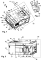
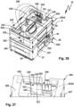
- a suction device 10 has a suction device housing 20 in which a suction turbine 11 of the suction device 10 is accommodated. With the suction turbine 11, a suction flow S can be generated, which can flow into the suction device housing 20 through a suction inlet 12. A suction hose SL can be connected to the suction inlet 12.
- the suction stream S flows through a dust collection space 21 of the suction device housing 20, in which particles contained in the suction stream S, for example dust, can be collected.
- a filter element 13, for example a plate filter, is arranged between the suction turbine 11 and the dust collection space 13, so that particles contained in the suction stream S are retained in the dust collection space 21. Downstream of the filter element 13, the suction flow S flows through the suction turbine 11 and flows out of the suction device housing 20 via an air outlet 22.
- the suction device 10 is, for example, a mobile electrical device that can be easily brought to its place of use.
- the suction device housing 20 is, for example, box-shaped and compact. However, the features and configurations explained below can also be used in a stationary electrical device.
- the suction device 10 can be placed with its underside 14 on a surface.
- the suction inlet 12 is arranged on an upper side 15 of the suction device 10 opposite the underside 14.
- the suction device 10 or its suction device housing 20 has longer long sides 16 and 17, of which the long side 16, for example, forms a front side and the long side 17 forms a back side of the suction device 10.
- the dust collecting space 21 and a suction turbine part 24 are provided, in which the suction turbine 11 is accommodated.
- the suction device housing 20 comprises a bottom wall 25, from which peripheral walls protrude, namely front and rear longitudinal side walls 26, 27 on the longitudinal sides 16 and 17 and longitudinal side walls 28 and 29 on the longitudinal sides 18 and 19 extending between the longitudinal side walls 26 and 27 overall enclose the housing interior 23.
- An intermediate wall 30 is arranged between the suction turbine part 24 and the dust collection space 21, which divides the housing interior 23, so to speak, into the suction turbine part 24 and the dust collection space 21.
- a flow opening 32 for the suction flow S is provided on the intermediate wall 30, through which the suction flow S can flow from the dust collection space 21 in the direction of the suction turbine part 24, which has a suction turbine receiving space 31 in which the suction turbine 11 is accommodated.
- the intermediate wall 30 could also be referred to as a bulkhead which, apart from the flow opening 32 and other small outflow openings 98, 108 to be described, separates the suction turbine part 24 from the dust collection space 21.
- the suction flow S flows out of the suction turbine receiving space 31 via the air outlet 22.
- the suction turbine part 24 and in particular the suction turbine receiving space 31 are closed by a cover wall 34, while the Dust collection chamber 21 is open on its side opposite to the bottom wall 25, for example at the top in the position of use.
- the air outlet 22 is arranged, for example, on one of the peripheral walls of the suction device housing 20, for example the front longitudinal side wall 26, but the longitudinal side walls 27 or 28 could also have an air outlet. In any case, it is advantageous if the air outlet 22 is not arranged on the bottom wall 25 and/or not on the cover wall 34, both of which are possible in principle.
- the dust collection room 21 has a receiving compartment 35 for a dust collection container 36.
- the dust collection container 36 is used to collect dirt.
- a filter bag can also be arranged in the dust collection container 36 or the dust collection space 21.
- the dust collection container 36 is designed, for example, as a type of cassette or module, which can be removed from the vacuum device housing 20 in order, for example, to empty dust from the dust collection container 36.
- the dust collection container 36 has a bottom wall 37, side walls 38 and 39 projecting from the bottom wall and a filter receptacle 40 for the filter element 13, which delimit an interior 43 of the dust collection container 36.
- the filter element 13 lies opposite the side wall 39.
- the side walls 38 extend between the filter receptacle 40 and the side wall 39.
- the side walls 38, 39 and an upper wall of the filter receptacle 40 delimit a receiving opening 41 which is opposite the bottom wall 37.
- the dust collection container 36 is therefore open at its top.
- a carrying handle 42 is pivotally articulated in the manner of a handle using pivot bearings 42A, with which the dust collection container 36 can be gripped.
- the carrying handle 42 When the carrying handle 42 is swung out, it can be grasped by an operator.
- the carrying handle 42 can move in the direction of the filter holder 40 can be pivoted so that the carrying handle 42 does not protrude or insignificantly protrudes from the receiving opening 41.
- the carrying handle 42 pivoted in the direction of the filter holder 40 locks the dust collection container 36 in the receiving compartment 35.
- the filter element 13 is expediently tensioned in the direction of the intermediate wall 30, so that a flow connection between the interior 43 of the dust collection container 36 and the flow opening 32 and thus the suction turbine 11 is established via the filter element 13.
- the suction turbine part 24 and the dust collection chamber 21 form components of a lower housing part 44 of the suction device housing 20.
- the lower housing part 44 can be closed by a cover 45.
- the suction device housing 20 is open or in an open position OD of the lid 45, the receiving compartment 35 is open in order to insert the dust collection container 36 into the receiving compartment 35 or remove it from it.
- the cover 45 has a cover body, for example a cover wall 46, which includes a suction turbine section 47 and a closure section 48.
- the suction turbine section 47 is assigned to the suction turbine part 24 and lies opposite the cover wall 34 when the lid 45 is closed.
- the closure section 48 has a seal 49 with which the interior 43 of the dust collection container 36 can be closed.
- the seal 49 rests, for example, on the end faces of the side walls 38 and 39 and a side wall delimiting the filter receptacle 40 and in particular on these side walls 38, 39 and the outer circumference of the filter receptacle 40, so that the closure section 48 tightly closes the dust collection container 36.
- the lid 45 can be locked to the lower housing part 44 in a closed position SD of the lid 45 using a locking device 50.
- the locking device 50 comprises a locking element 51 pivotably mounted on the cover 45, which in a locking position is in engagement with a locking element 52 on the lower housing part 44 and can be pivoted into a release position in which it is out of engagement with the locking element 52.
- the locking element 51 is therefore designed in the manner of a swivel lock.
- the locking element 52 is arranged on the longitudinal side wall 26 of the lower housing part 44.
- the locking element 52 is designed, for example, as a locking projection.
- the locking element 51 is arranged on a front side of the lid 45 assigned to the front or front longitudinal side 16 of the suction device 10.
- the cover 45 is pivotally connected to the lower housing part 44 by means of pivot bearings 53 and can be pivoted between its open position OD and its closed position SD.
- the pivot bearings 53 are arranged, for example, on the longitudinal side wall 27, in particular its upper end face or narrow side.
- a band 53A optionally present between the cover 45 and the lower housing part 44, which is fastened, for example, to the cover wall 34 and a wall surface of the closure section 48 opposite this, limits the pivoting path of the cover 45 in the direction of its open position OD.
- feet 54, 55 are arranged, with which the suction device housing 20 can be placed on a surface, but also in engagement with receptacles 56, 57 with another suction device housing 20 of a similar suction device 10 in intervention can be brought.
- the feet 54 and the receptacles 56 are arranged close to the rear longitudinal side wall 27.
- the receptacles 56 and the feet 54 have rear gripping contours 56A, 54A, which can be brought into and out of engagement with one another transversely to a stacking direction or stacking axis SR and, when they are in engagement with one another, suction device housings 20 stacked on top of one another along the stacking axis SR to be connected in a tensile manner.
- the rear gripping contours 56A, 54A form components of coupling means 58.
- the coupling means 58 for coupling containers stacked on top of one another or suction device housings 20 further comprise a locking element 59, which is arranged in the manner of the locking element 52 on the lower housing part 44, but not close to the free end face of the longitudinal side wall 26, but close to the bottom wall 25.
- the locking element 51 also forms a component the coupling means 58. If the locking element 51 of a lower container or suction device housing 20 is brought into engagement with the locking element 59 by pivoting the locking element 51, the containers or suction device housings 20 are also in the area of the front or front long side 16 coupled to each other and thus a tensile connection of these suction device housings 20 is produced in the direction of the stacking axis SR or in the stacking direction.
- the suction inlet 12 can be closed by a closure element 60.
- the closure element 60 has a closure body 61 which can be inserted into the suction inlet 12.
- the closure body 61 is therefore designed as a plug-in projection or plug-in body.
- the closure element 60 is movably mounted on the suction device housing 20 by means of a bearing 62 between a closure position V and a release position FS, the closure element 60 closing the suction inlet 12 in the closure position V and releasing it in the release position FS.
- the suction inlet 12 is free or open for arranging, in particular for inserting, the suction hose SL.
- the bearing 62 is, for example, a pivot bearing, by means of which the closure element 60 is pivotally mounted about a pivot axis SC.
- the pivot axis SC is, for example, orthogonal to the top surface of the top 45A of the lid 44 or to the top surface of the suction device housing 20.
- the bearing 62 includes a bearing projection 63 on the closure element 60, which engages in a bearing receptacle 64 on the top 15 of the lid 44.
- the bearing holder 64 is, for example, as a passage opening on the cover body or the top wall 46.
- the bearing projection 63 penetrates the passage opening.
- the closure body 61 and the bearing projection 63 are arranged on an arm body 65 of the closure element 60.
- the arm body 65 extends along a longitudinal axis L60 between the bearing projection 63 and the closure body 61, which are arranged at opposite longitudinal end regions of the arm body 65.
- the arm body 65 is preferably plate-like and/or is designed in the manner of a tab.
- the cover 45 and thus the suction device housing 20 have a closure element receptacle 67 for the closure element 60.
- the closure element receptacle 67 is designed as a recess on the top 45A of the lid 45.
- An upper side 66 of the closure element 60 facing away from the upper side 45A of the lid 45 does not protrude in front of the upper side 45A of the lid 45 or is behind this upper side 45A, which is not shown in the exemplary embodiment, but represents an option.
- the top 45A of the lid 45 is available for stacking another container or suction device housing 20 or the container attachment 200 explained below, without the closure element 60 representing an interfering contour.
- the closure element receptacle 67 is, for example, approximately triangular in plan view, the bearing 62 being arranged in a corner region of this triangle and the suction inlet 12 and a provision receptacle 68 being arranged in the other corner regions.
- the provision receptacle 68 is also designed as a plug-in receptacle and has a peripheral wall 69 and a base 70.
- the suction inlet 12 is designed as a plug-in receptacle with a peripheral wall 71, into which either the form-fitting body 61 or the suction hose SL can be inserted.
- the closure body 61 projects in front of the arm body 65 in the manner of a closure projection and has a peripheral wall 72 and a base 73.
- a handle section 74 protrudes from the floor 70 into an interior space delimited by the peripheral wall 72 and forms a handle 74A for gripping the closure element 60.
- the closure body 61 preferably the closure element 60 as a whole, consists of a flexible material, which on the one hand enables a clamping or sealing fit in the suction inlet 12 or the provision receptacle 68, but on the other hand also enables comfortable handling.
- the arm body 65 is flexible, so that the closure body 61 can be moved out of the suction inlet 12 or the provision receptacle 68 while bending the arm body 65.
- a correspondingly movable mounting or pivotable mounting on the bearing 62 would also be possible in order to pivot the closure element 60 back and forth not only about the pivot axis SC between the provision receptacle 68 and the suction inlet 12, but also out of engagement or transversely to the pivot axis SC to pivot into engagement with the provision receptacle 68 and the suction inlet 12.
- the closure element 60 can be movably mounted in the bearing receptacle 65 about a pivot axis SQ that runs transversely to the pivot axis SC, so that the closure element 60 can be moved away from the top 45A out of engagement with the suction inlet 12 or the provision receptacle 68.
- the bearing projection 63 can have a significantly smaller diameter than the bearing receptacle 64 and thus have a movement play transverse to the pivot axis SC in the bearing holder 64.
- the handle section 74 includes a base wall 75 from which side walls 76 protrude.
- the base wall 75 and the side walls 76 form an approximately U-shaped or V-shaped configuration in cross section.
- the side walls 76 extend between the base wall 75 and the bottom 73 of the closure body 61.
- the base wall 75 and the bottom 70 are, for example, parallel to one another.
- the side walls 76 lie opposite the peripheral wall 72 of the closure body 61.
- the side walls 76 are advantageously long such that the handle section 74 extends to the arm body 65.
- the base wall 75 is approximately aligned with the arm body 65 and/or with the top 45A of the lid 45. This makes gripping the handle 74A easier.
- a seal 77 for example in the form of ribs or sealing projections 77A, which rests on the peripheral wall 71 or the peripheral wall 72 in a sealing or clamping fit when the closure body 61 engages in the provision receptacle 68 or the suction inlet 12 .
- the closure body 61 is reliably held in the provision receptacle 68 or the suction inlet 12.
- the seal 77 ensures that the suction inlet 12 is sealed when no suction hose SL is inserted, so that no dust or similar other dirt can escape from the dust collection container 36 or the dust collection space 21 into the environment. Nevertheless, the operator easily manages to actuate the closure element 60 from the provision receptacle 68 into the suction inlet 12 or vice versa.
- Insertion into the provision receptacle 68 or the suction inlet 12 is achieved, for example, by pressing DV on the base wall 75 of the handle section 74.
- the handle section 74 can be gripped with a clamp-like handle movement and pulled out of the suction inlet 12 or the provision receptacle 68 in the opposite direction to the actuation direction of the pressure actuation DV.
- the side walls 76 are parallel to one another or, as in the exemplary embodiment, inclined obliquely to one another at a small angle, so that an operator can grasp the two side walls 76 like a clamp when gripping the handle section 74 and move them towards one another, for example by a pressure load DO.
- sections of the peripheral wall 72 and thus the seal 77 are actuated away from the peripheral wall 71 or 72, so that the clamping fit of the closure body 61 on the provision receptacle 68 or the suction inlet 12 is canceled or at least less tight.
- the side walls 76 give way under pressure when the operator acts on them and form recessed grips, so that handling is made even easier.
- rib structures or similar other gripping structures can also be provided on the handle section or handle of a closure element in order to make handling easier.
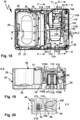
- the suction device 10 advantageously has a container attachment 200 or is compatible with a container attachment 200.
- the container attachment 200 preferably has the same contour on its outer circumference as the suction device housing 20.
- the container attachment 200 can be stacked on the suction device 10, namely its suction device housing 20, and connected to it using the coupling means 58 already explained.
- the container attachment 200 comprises a suction device housing 220 with a bottom wall 225, from which longitudinal side walls 226, 227, 228 and 229 protrude, which overall delimit a receiving space 223 of the container attachment 200.
- the receiving space 223 is suitable for holding the suction hose SL.
- a handle 224 receiving space 223 protrudes from the bottom wall 225.
- the handle 224 is designed in the manner of a handle, so that the container attachment 200 attached to the suction device housing 20 serves as a carrying handle for carrying a stack 9 consisting of the suction device 10 and the container attachment 200. This forms a suction device housing 20 stacking housing 20A.
- the container attachment 200 forms a stacking container 200A.
- the suction hose SL can be wrapped around the handle 224 so that it serves as a wrapping aid.
- a passage 222 for the suction hose SL is provided on the bottom wall 225, which is aligned with the suction inlet 12 when the container attachment 200 is attached to the suction device 10. Furthermore, a lateral passage 221 for the suction hose SL is provided on the longitudinal side wall 28.
- locking elements 251, 259 are provided as coupling means 58, which are identical in construction and/or compatible with the locking elements 51 and 59.
- the locking element 51 of the suction device 10 can be brought into engagement with the locking element 259 in order to form the stack 9 consisting of the suction device 10 and the stacked container attachment 200.
- the coupling means 58 also easily bring about a firm connection between the container attachment 200 and the suction device housing 20 transversely to the stacking axis SR.
- Further containers for example containers for transporting tools, can be stacked or underneath the stack 9, which can be coupled to the container attachment 200 or the suction device housing 20 using coupling means compatible with the coupling means 58.
- the container attachment 200 can also be arranged under the suction device housing 20 and connected to it using the coupling means 58 to form a stack.
- a further container attachment 200 (not shown in the drawing) or a further suction device 10 (not shown), for example on the in Figure 6
- Upper container attachment 200 is stacked and coupled to it to form a stack using coupling means that are compatible with the coupling means 58.
- the suction device 10 as a suction device that can be operated via a power supply network.
- the suction device 10 is not only extremely compact, but can also be used flexibly in that the suction device 10 has a power supply device 80 to which energy storage devices 170, for example so-called battery packs, can be connected.
- energy storage devices 170A, 170B For power supply, for example, two similar energy storage devices 170, hereinafter also referred to as energy storage devices 170A, 170B, are available.
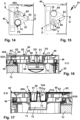
- the power supply device 80 includes an energy storage receptacle 81 in the area of the suction turbine part 24.
- the energy storage receptacle 81 extends between the longitudinal side wall 28 and the intermediate wall 30 almost over the entire distance between the longitudinal side wall 28 and the intermediate wall 30, so that in the energy storage receptacle 81 two energy storage devices 170 can be arranged.
- the energy storage receptacle 81 includes an insertion opening 82 through which the energy storage devices 170 can be inserted into the energy storage receptacle 81.
- the insertion opening 82 is delimited by side walls 83, 84, which run next to the side wall 28 of the suction device housing 20 and the intermediate wall 30 of the suction device housing 20, in particular parallel to the same. Between Side walls 83 and 84 extend a side wall or connecting wall 85 located closer to the cover 45 and a side wall or thick wall 86 closer to the bottom wall 25 or formed by the bottom wall 25.
- the energy storage receptacle 81 is delimited by a bottom wall 87 which corresponds to the insertion opening 82 is opposite.
- Interfaces 90 are arranged on the side walls 83, 84, with which the energy storage devices 170 can be connected, which have energy storage interfaces 190 that match the interfaces 90.
- the interfaces 90, 190 comprise complementary longitudinal guide contours 91, 191 which can be inserted into one another along a plug-in axis SA.
- the longitudinal guide contours 91, 191 include longitudinal grooves and longitudinal projections that can engage with one another.
- Behind-grip contours 91A, 191A of the interfaces 90, 191 extend transversely to the respective plug-in axle SA, with which the energy storage devices 170 can be brought into positive engagement with the device interfaces 90 transversely to the respective plug-in axle SA.
- the interfaces 90, 190 can be connected to one another in a form-fitting manner, apart from sliding mobility along the respective plug-in axis SA.
- the interfaces 90, 190 include locking devices 92, 192 in order to lock the energy storage devices 170 on the device interfaces 90.
- the latching devices 92 are designed, for example, as latching receptacles 93, into which latching projections 193 of the latching devices 192 can engage in a latching manner, so that the energy storage devices 170 are held in a non-displaceable manner at the interfaces 90 with respect to the plug-in axle SA.
- the locking projections 193 are, for example, spring-loaded or resilient in the direction of their locking position, in which they engage in the locking receptacles 93 and can be brought out of engagement with the locking receptacles 93 against the aforementioned spring loading.
- the interfaces 90, 190 include contact arrangements 94, 194 to establish electrical connections between the energy storage 170 and the suction device 10.
- the contact arrangements 94, 194 include, for example, energy supply contacts 95, 195 with different polarity, for example a positive potential and ground, as well as data contacts 96, 196 for data transmission between the suction device 10 and the respective energy storage 170.
- data transmission for example, sees a digital bus data transmission , especially with an I2C bus.
- Each energy storage device 171 has an energy storage housing 171, which comprises longitudinal side walls 172 on its long sides 172A and end side walls 173, 174 extending between them.
- a bottom wall 175 extends between the side walls 172-174 and, opposite it, an interface wall 176, on which the energy storage interface 190 is arranged.
- the interface wall 176 may have a stepped shape so that, for example, the data contacts 196 are at a greater distance from the bottom wall 175 than the power supply contacts 195.
- the power supply contacts 195 and the data contacts 196 are arranged one behind the other with respect to the plug-in axle SA.
- the data contacts 196 are arranged at the front with respect to the insertion direction along the insertion axis SA, that is, closer to the end wall 173, while the supply contacts 195 are arranged at the rear in the insertion direction along the insertion axis SA, i.e. near the end wall 174.
- the energy storage housing 171 has an interior 177 in which battery cells 178 are arranged to protect them from environmental influences. However, the battery cells 178 heat up, for example when charging or discharging, i.e. when the suction device 10 is operated using the energy storage 170.
- each energy storage device 170 has a fan 179.
- the fan 179 generates a cooling air flow KL, which flows into the interior 177 through an energy storage inflow opening 180 and flows out of it through an energy storage outflow opening 181.
- the energy storage inflow opening 180 is arranged on the bottom wall 175, while the energy storage outflow opening 181 is arranged on the interface wall 176.
- the energy storage inflow openings 180 and the energy storage outflow openings 181 are arranged at opposite longitudinal end regions of the energy storage 170, namely close to the end wall 174 and the end side wall 173, so that the cooling air flow KL, for example a cooling air flow KLA in the energy storage 170 and a cooling air flow KLA in the energy storage 170B Cooling air flow KLB flows through a respective energy storage device 170, so to speak, from back to front in relation to the plug-in direction or plug-in axle SA.
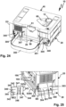
- the device interfaces 90 are arranged on opposite sides of the energy storage receptacle 81, namely on the side walls 83 and 84. Accordingly, the energy storage devices 170 are accommodated in the energy storage receptacle 81 with opposite bottom walls 175.
- operating elements 197 are provided on the longitudinal side walls 172 of the energy storage housing 171.
- An operator can therefore grasp the energy storage housing 171 laterally and/or like a clamp, so to speak, in order to simultaneously act on the two operating elements 197 arranged on the opposite longitudinal side walls 172 in order to bring the locking projections 193 out of engagement with the locking receptacles 93, so that the respective energy storage 170 can be removed from the device interface 90.
- the receptacles 81 allow convenient handling because there are operating rooms 88 and 89 between the connecting walls 85, 86 and the energy storage units 170 inserted into the energy storage receptacle 81, into which an operator can operate the operating elements 197, for example printing surfaces or Have tactile surfaces, can grasp.
- the operating rooms 88 and 89 are, so to speak, uniform or continuous operating rooms because there is no separating component between the energy stores 170 accommodated in the energy storage receptacle 81. If, for example, the energy storage 170 would be accommodated in the energy storage receptacle 81 with energy storage interfaces 190 facing each other, there would have to be an intermediate wall in the energy storage receptacle 81 on which the device interfaces 90 are arranged.
- the operator can grasp the energy storage 170, for example on its longitudinal side walls 172, in order to remove it from the energy storage receptacle 81. Operation is also made easier when inserting the energy storage device 170 into the energy storage receptacle 81, because in this case too the operator can grasp the longitudinal side walls 172 in order to connect a respective energy storage device 170 to the device interface 90 assigned to it.
- the side walls 83, 84 are advantageously spaced from one another in such a way that the energy storage devices 170 connected to the device interfaces 90 have a distance between their bottom walls 175, so that the cooling air flow KL can flow into the space between the bottom walls 175.
- Outflow openings 97 and 98 which are close to the device interfaces 90 and thus close to the energy storage outflow openings 181 of the energy storage 170 on the side walls 83 and 84 of the energy storage, serve to dissipate the cooling air flows KL from the energy storage 170 arranged at the device interfaces 90.
- Recording 81 are arranged.
- the outflow openings 97 and 98 are referred to below as receiving outflow openings because of their arrangement in the energy storage receptacle 81 and are located close to the bottom wall 87, so that little or no heat accumulates in the energy storage receptacle 81.
- the receiving outflow opening 98 opens directly into a space between the intermediate wall 30 and the filter element 13, so that a cooling air channel 99 is formed between the intermediate wall 30 and the filter element 13, which leads from the receiving outflow opening 98 to the flow opening 32 on the intermediate wall 30 .
- a cooling air flow KLA can therefore flow on the side wall 84 arranged energy storage 170 flow out of the receiving outflow opening 98 and is sucked out by the suction turbine 11 via the cooling air duct 99.
- the suction turbine 11 can even increase the cooling air flow KLA, which is indicated schematically by arrows.
- the energy storage 170B can be cooled by a cooling air flow KLB, which can flow out of the energy storage receptacle 81 through the receiving outflow opening 97.
- the receiving outflow opening 97 forms a channel inflow opening 97A for a cooling air duct 100.
- cooling air duct 100 does not lead directly to the flow opening 32, but rather opens into a further cooling air duct 101, which serves to cool other components of the suction device 10, for example to cool a power supply device 140 as well as a permanent one Cooling of the suction turbine 11.
- the suction turbine 11 is, for example, a so-called through-flow turbine or a turbine that is cooled or can be cooled by the suction flow conveyed by it.
- Such permanent cooling of the suction turbine 11 is particularly important if it cannot otherwise suck in sufficient air on the inflow side. Such a situation occurs, for example, when the suction inlet 12 is blocked or blocked, when the filter element 13 is no longer permeable, when the dust collection space 21 is overfilled or the like.
- the suction turbine 11 is a so-called through-flow turbine.
- the suction turbine 11 has the suction turbine inflow opening on its side facing the flow opening 32 11A on and on its side facing away from the flow opening 32 at least one, preferably several suction turbine outflow openings 11B.
- a seal 11E is provided between, on the one hand, the intermediate wall 30 and, on the other hand, the end face of the suction turbine 11, which faces the intermediate wall 30 and has the suction turbine inflow opening 11A, so that it rests tightly against the intermediate wall 30 and the suction flow S flows through the flow opening 32 can flow, but does not flow into the suction turbine receiving space 31, in which the suction turbine 11 is arranged.
- the suction turbine receiving space 31 is delimited in the area of the suction turbine outflow openings 11B by a side wall 31A.
- a suction turbine bearing element 11F is advantageously arranged, which is elastically flexible, so that this suction turbine bearing element 11F and the seal 11E support the suction turbine 11 in the suction device -Store housing 20 in a vibration-damped manner.
- the suction turbine 11 has a schematically illustrated fan 11C and an electric drive motor 11D for driving the fan 11C.
- the drive motor 11D is cooled by the suction flow S during normal operation of the suction device 10, i.e. when the suction flow S flows.
- the suction device 10 has a power supply device 140.
- the current supply device 140 includes, for example, one or more power electronic semiconductor elements 141, for example thyristors, MosFets or the like.
- the semiconductor elements 141 heat up during operation, namely when the suction turbine 11 is energized.
- the power supply device 140 is arranged on a circuit board 104, which is sandwiched between the longitudinal side wall 28 and the side wall 83 of the energy storage receptacle 81 of the power supply device 80 is.
- the circuit board 104 also partially extends into a gap between the side wall 28 of the side wall 31A.
- the power supply device 140 is connected to the device interfaces 90A, 90B, in particular the power supply contacts 95, using lines 143. Lines 144 connect the power supply device 140 to the suction turbine 11.
- the suction device 10 advantageously has a control 150.
- the controller 150 includes, for example, a processor 151 and memory 152, in which at least one control program 153 is provided for controlling, for example, the suction turbine 11.
- controls 155 which are arranged on a control wall 156, an operator can control the suction device 10.
- the control wall 156 is arranged on the side wall 28.
- the controller 150 is electrically connected to the controls 155. With the controls 155, the suction device 10 can be switched on or off, for example. Furthermore, the performance of the suction turbine 11 can be adjustable using the operating elements 155.
- a display 157 is advantageously provided on the control wall 156, for example to display a status of the suction device 11.
- the control 150 also generates heat, the removal of which is advantageously solved in the suction device 11, as will become clear below.
- the cooling air channel 101 is fluidly connected to the receiving outflow opening 97. Air can thus flow into the cooling air channel 101 via the receiving outflow opening 97, for example the cooling air flow KLB. However, the cooling air flow KLB is already heated by the cooling of the energy storage 170B.
- Ambient air i.e. generally cooler air
- the channel inflow opening 102 is, for example, close to the bottom wall 25 the area of the longitudinal side wall 28 facing the bottom wall 25.
- a protective grille 102A is advantageously arranged at the channel inflow opening 102.
- the cooling air flow KLC flows via the channel inflow opening 102 into a channel section 103A of the cooling air channel 101, which runs between the circuit board 142 and the side wall 31A.
- the cooling air flow KLC therefore flows behind the circuit board 142 or the cooling air flow KLC flows past the circuit board 142.
- the channel section 103A is selected so that the cooling air flow KLC essentially flows past the current supply device 140, i.e. in particular the semiconductor elements 141, which become particularly warm during operation of the suction device 11. However, such warming and, in the worst case, heating is effectively counteracted using the cooling air flow KLC.
- the channel section 103A opens into a hose receptacle 104, in which a hose 110, i.e. a tubular body 110A for guiding cooling air, is accommodated.
- the hose receptacle 104 has, for example, a plug-in receptacle 105 into which the hose 110 is inserted, and an air guide surface 106 on a wall 107.
- the cooling air flow KLC flowing out of the channel section 103A is directed via the air guide surface 106 into an inlet opening 111 of the hose 110. There is a distance between the inlet opening 111 and the air guide surface 106 or the wall 107 so that the cooling air flow KLC can flow unhindered into the inlet opening 111.
- the design and/or a cross section of the plug-in receptacle 105 ensures that the hose 110 is only compressed to such an extent that it clamps securely in the plug-in receptacle 105, but is not compressed in such a way that its flow cross-section is no longer sufficient to pass through the cooling air flow KLC .
- the plug-in receptacle 105 is advantageously opposite a plug-in stop 105A, on which a jacket of the cooling air hose 110 can be inserted when inserted into the Plug socket 105 can strike.
- the plug stop 105A is at a distance from the air guide surface 106.
- the inlet opening 111 cannot be closed by the air guide surface 106 because of the plug-in stop 105A.
- the cooling air flow KLB can flow past the circuit board 142 and/or in an intermediate space between the circuit board 142 and the cover wall 34 and into the inlet opening 111 of the cooling air hose 110, so that the cooling air hose 110 carries both the cooling air flow KLB and the cooling air flow KLC in the direction of the channel outflow opening 108.
- the cooling air hose 110 thus provides a common channel section 103B for the cooling air flows KLB and KLC.
- the cooling air hose 110 has a hose section 112 which leads the cooling air flow KLC and/or the cooling air flow KLB past the suction turbine receiving space 31 to a channel outflow opening 108 which is arranged on the intermediate wall 30 and into the space between the intermediate wall 30 and the filter element 13 opens out. There, the cooling air flow KLC and/or the cooling air flow KLB can flow in the direction of the flow opening 32 in order to be sucked out by the suction turbine 11.
- the hose section 112 has an arcuate course. An end region 113 of the hose section 112 is held in the area of the channel outflow opening 108 in a receptacle 109, which is designed, for example, as a plug-in receptacle.
- cooling air flow KLC cools the power supply device 140, but also the suction turbine 11.
- the cooling air channels 99 and 100 advantageously have smaller flow cross sections than the cooling air channel 101.
- the cooling air channel 101 namely cools the Power electronics, for example the semiconductor elements 141. This measure helps ensure that sufficient cooling air flows through the cooling air channel 101 and not, so to speak, past it through the cooling air channels 99 and / or 100.
- the channel inflow openings 97A, 98A and 102 are permanently open.
- the cooling air flows KLA, KLB and KLC can thus contribute permanently to cooling the suction turbine 11.
- a sensor 154 is arranged on the suction turbine 11, the sensor signals of which are evaluated by the controller 150.
- the sensor 154 includes or is, for example, a temperature sensor and/or pressure sensor and/or flow sensor. Due to the permanent cooling of the suction turbine 11 using the cooling air flows KLA, KLB and KLC, even when the suction flow S is interrupted or does not flow, there is sufficient flow pressure at the sensor 154 so that it can report valid temperature signals to the controller 150.
- controller 150 is designed to monitor a volume flow of the suction flow S, for example using the at least one control program 153.
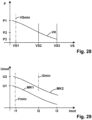
- the suction flow S has a volume flow VS, which has a pressure-dependent course depending on a pressure P.
- a characteristic curve VK of a volume flow of the suction flow S is in Figure 28 shown schematically.
- the volume flow VS has values VS1, VS2 and VS3 in liters per second.
- the suction flow S should not fall below a minimum speed of, for example, 20 m/s, so that, for example, a so-called dust class is maintained, according to which the suction device 10 always ensures sufficient suction for this dust class.
- the required minimum speed of the suction flow S results in a minimum value VSmin for the volume flow of the suction flow S, which is, for example, approx. 10 l/s with a hose diameter of 27 mm of the suction hose SL.
- the controller 150 can use engine characteristics MK1 and MK2 as well as other engine characteristics of the drive motor 11D of the suction turbine 11, not shown in the drawing, to create a characteristic VK of the volume flow of the Determine the suction flow S, because both the characteristic curve VK and the motor characteristic curves MK1 and MK2 have a substantially constant, in particular essentially linear, course in the area relevant for monitoring the volume flow or the flow velocity of the suction flow S.
- the motor characteristics MK1 and MK2 depend on voltages U1 and U2 with which the drive motor 11D is operated.
- the motor characteristics MK1 and MK2 are proportional to a current curve of the motor current Imot, with which the drive motor 11D is energized by the current supply device 140.
- the controller 150 controls the energization device 140 and receives feedback from it, for example, the motor voltage present, for example the motor voltages U1 and U2, as well as the respective motor current Imot for energizing the drive motor 11D.
- the controller 150 recognizes that the flow velocity of the Suction flow S is too low and, for example, issues a warning on display 157.
- the controller 150 can alternatively or additionally also output an acoustic warning on a loudspeaker or other acoustic output means 158.
- a carrying strap 350 is advantageously suitable for conveniently transporting the suction device 10 or the stack 9 consisting of the suction device 10 and container attachment 200 or the container attachment 200 alone.
- the carrying strap 350 can be ergonomically adapted to the respective carrying situation using a length adjustment device 351.
- the carrying strap 350 can be attached either to the suction device 10 or to the container attachment 200.
- the carrying strap 350 has a fastening device 340 on each of its longitudinal end regions.
- the fastening devices 340 can be brought into engagement with fastening receptacles 300 of the suction device 10 or with fastening receptacles 320 of the container attachment 200 as required.
- the fastening devices 340 have base bodies 341 which are designed like a plate.
- the base bodies 341 have rear gripping contours 342 on their longitudinal sides, which, in cooperation with rear gripping contours 302 of the fastening receptacle 300, serve as longitudinal guides along which the fastening devices 340 can be inserted into a respective fastening receptacle 300 along a plug-in axis S300.
- the base body 341 In the plugging direction at the front with respect to a plug-in axle S300, the base body 341 has a further rear gripping contour 343, the front section 343A of which abuts against a stop 303 of the fastening receptacle 300 at the end of the plug-in movement along the plug-in axis S300.
- a latch 304 of the fastening receptacle 300 which can be actuated using an actuating surface or actuating contour 305, can move into its locking position, in which it passes behind and/or over a rear gripping contour 344 of the fastening device 340.
- the latch 304 is, for example, spring-loaded in its locking position and can be actuated against this spring loading by means of an actuating surface 305 with an unlocking actuation BE in the direction of its release position. Then the latch 304 comes out of engagement with the rear gripping contour 344, so that the fastening device 300 can be moved out of the fastening receptacle 300 designed as a plug-in receptacle.
- the rear gripping contour 343 and the rear gripping contour 344 extend between the rear gripping contours 342.
- the rear gripping contour 343 and the rear gripping contour 344 are arranged on opposite longitudinal end regions of the base body 341.
- the fastening receptacles 320 are also designed as plug-in receptacles.
- a fastening device 340 can be inserted into a respective fastening receptacle 320 along a plug-in axis S320 or can be moved out of the fastening receptacle 320 along the plug-in axis S320.
- the rear gripping contours 343 and 344 of the fastening device 340 act as longitudinal guide contours, which can come into engagement with longitudinal guide contours or rear gripping contours 322 of the fastening receptacle 320 and guide the fastening device 340 along the plug-in axle S320.
- One of the rear gripping contours 342 of the fastening device 340 which is at the front in the plugging direction with respect to the plug-in axle S320, abuts a stop 323 on the bottom or end of the fastening receptacle 320 with respect to the plug-in axle S320.
- a rear gripping contour for receiving this rear gripping contour 342 can optionally be provided there.
- a latch 346 of the fastening device 340 can also come into engagement with a locking contour 324 of a locking element 325 of the fastening receptacle 320, so that the fastening device 340 is locked in the fastening receptacle 320.
- the latch 346 is designed as a resilient tongue or resilient element with respect to the base body 341 and has an actuating surface 345 with which it can be brought out of engagement with the locking contour 324 of the fastening receptacle 320, which is indicated by an arrow or an actuation BE2 in the drawing.
- the fastening devices 340 have belt receptacles 347 for the carrying strap 350.
- the carrying strap 350 can, for example, be inserted through a push-through opening 348 of a belt receptacle 347 and be held frictionally on the belt receptacle 347 by appropriate loop measures.
- the fastening receptacles 320 of the container attachment 200 are located on the longitudinal side walls 228 and 229 in such a way that the carrying strap 340 can be brought into engagement with the fastening receptacles 320 by bridging the receiving space 223 of the container attachment 200.
- the stack 9 can, so to speak, hang down from the carrying strap 350 and be carried comfortably.
- the fastening receptacles 300 enable the suction device 10 to be carried in the manner of a shoulder bag.
- the fastening receptacle 300 is arranged on one of the longitudinal side walls 26, 27, 28 or 29, specifically on the longitudinal side wall 26 in the exemplary embodiment. In any case, it is advantageous if the fastening receptacles 300 are arranged on narrow sides of the suction device housing 20.
- fastening receptacle 300 is arranged at longitudinal end regions of the longitudinal side wall 26, i.e. close to the longitudinal side walls 28 and 29, so that the carrying strap 350 can serve a central section of the longitudinal side wall 26 as a strap or hand carrying handle suitable for hanging on a shoulder .
Landscapes
- Engineering & Computer Science (AREA)
- Mechanical Engineering (AREA)
- Power Engineering (AREA)
- Battery Mounting, Suspending (AREA)
- Packages (AREA)
- Auxiliary Devices For Machine Tools (AREA)
Applications Claiming Priority (2)
| Application Number | Priority Date | Filing Date | Title |
|---|---|---|---|
| DE102021121708 | 2021-08-20 | ||
| DE102021129515.7A DE102021129515A1 (de) | 2021-08-20 | 2021-11-12 | Elektrisches Gerät, insbesondere Sauggerät oder Werkzeugmaschine |
Publications (2)
| Publication Number | Publication Date |
|---|---|
| EP4137029A1 EP4137029A1 (de) | 2023-02-22 |
| EP4137029B1 true EP4137029B1 (de) | 2024-02-14 |
Family
ID=82701885
Family Applications (1)
| Application Number | Title | Priority Date | Filing Date |
|---|---|---|---|
| EP22186384.8A Active EP4137029B1 (de) | 2021-08-20 | 2022-07-22 | Elektrisches gerät, insbesondere sauggerät oder werkzeugmaschine |
Country Status (7)
| Country | Link |
|---|---|
| US (1) | US20230076422A1 (enExample) |
| EP (1) | EP4137029B1 (enExample) |
| JP (1) | JP2023029313A (enExample) |
| CN (1) | CN115707421A (enExample) |
| AU (1) | AU2022209260A1 (enExample) |
| DK (1) | DK4137029T3 (enExample) |
| FI (1) | FI4137029T3 (enExample) |
Families Citing this family (4)
| Publication number | Priority date | Publication date | Assignee | Title |
|---|---|---|---|---|
| WO2023273787A1 (zh) * | 2021-06-29 | 2023-01-05 | 南京泉峰科技有限公司 | 工具箱系统 |
| EP4512578A1 (de) * | 2023-08-24 | 2025-02-26 | Festool GmbH | Vakuum-spannvorrichtung |
| EP4520236A1 (de) * | 2023-09-05 | 2025-03-12 | Hilti Aktiengesellschaft | Werkzeugmaschine mit integrierter ermittlung eines volumen-stroms und verfahren zum betrieb der werkzeugmaschine |
| CN118137623B (zh) * | 2024-05-06 | 2024-07-09 | 中骏智能(泉州)有限公司 | 一种储能升压一体机 |
Family Cites Families (9)
| Publication number | Priority date | Publication date | Assignee | Title |
|---|---|---|---|---|
| DE102005007923B4 (de) * | 2005-02-11 | 2006-10-19 | Alfred Kärcher Gmbh & Co. Kg | Reinigungsgerät |
| DE102010043577A1 (de) * | 2010-11-08 | 2012-05-10 | Alfred Kärcher Gmbh & Co. Kg | Sauggerät |
| JP2014147904A (ja) * | 2013-02-01 | 2014-08-21 | Makita Corp | 集塵機 |
| US9980618B2 (en) * | 2014-02-13 | 2018-05-29 | Makita Corporation | Dust collecting device |
| US10448797B2 (en) * | 2016-10-19 | 2019-10-22 | Tti (Macao Commercial Offshore) Limited | Vacuum cleaner |
| DE102016120329A1 (de) * | 2016-10-25 | 2018-04-26 | Festool Gmbh | Anschlussvorrichtung eines Elektrogeräts oder eines Energiespeichers |
| US11529637B2 (en) * | 2017-04-11 | 2022-12-20 | Festool Gmbh | Cyclone pre-separator and arrangement |
| CN112310493B (zh) * | 2019-11-29 | 2021-12-07 | 宁德时代新能源科技股份有限公司 | 失效电池单元的处理方法、电池模块、电池组和装置 |
| DE202020105705U1 (de) * | 2020-10-05 | 2020-11-18 | Einhell Germany Ag | Elektrowerkzeugmaschine |
-
2022
- 2022-07-22 EP EP22186384.8A patent/EP4137029B1/de active Active
- 2022-07-22 DK DK22186384.8T patent/DK4137029T3/da active
- 2022-07-22 FI FIEP22186384.8T patent/FI4137029T3/fi active
- 2022-07-27 AU AU2022209260A patent/AU2022209260A1/en active Pending
- 2022-08-18 US US17/890,326 patent/US20230076422A1/en active Pending
- 2022-08-19 JP JP2022130920A patent/JP2023029313A/ja active Pending
- 2022-08-19 CN CN202210999312.2A patent/CN115707421A/zh active Pending
Also Published As
| Publication number | Publication date |
|---|---|
| AU2022209260A1 (en) | 2023-03-09 |
| DK4137029T3 (da) | 2024-02-26 |
| CN115707421A (zh) | 2023-02-21 |
| FI4137029T3 (fi) | 2024-03-01 |
| EP4137029A1 (de) | 2023-02-22 |
| JP2023029313A (ja) | 2023-03-03 |
| US20230076422A1 (en) | 2023-03-09 |
Similar Documents
| Publication | Publication Date | Title |
|---|---|---|
| EP4137029B1 (de) | Elektrisches gerät, insbesondere sauggerät oder werkzeugmaschine | |
| DE60223488T2 (de) | Tragbarer Behälter für ein elektrisches Handwerkzeug mit Fähigkeit zum Absaugen und Sammeln von Staub | |
| EP2897513B1 (de) | Staubsauger mit batteriedeckel | |
| EP4137024B1 (de) | Sauggerät mit einem verschlusselement | |
| DE102014200663A1 (de) | Akkubetriebener Handstaubsauger | |
| EP1171261A1 (de) | Handwerkzeugmaschine mit staubabsaugung | |
| EP2895045B1 (de) | Staubsauger | |
| EP3609380A1 (de) | Zyklonvorabscheider und anordnung | |
| DE102010064026A1 (de) | Staubsauer mit temperiertem Akkumulator | |
| DE202015004939U1 (de) | Staubsammler | |
| EP4137023B1 (de) | Sauggerät | |
| DE102012213047A1 (de) | Handwerkzeugkoffer | |
| DE202011001475U1 (de) | Elektrowerkzeugmaschine, insbesondere eine Schleif- oder Poliermaschine | |
| WO2022122280A1 (de) | Sauggerät mit mindestens einer aufnahme für eine batterie | |
| DE102010023829A1 (de) | Motorbetriebenes Werkzeug | |
| DE212020000707U1 (de) | Elektrowerkzeugsystem | |
| EP1784287A1 (de) | Wechselhandwerkzeugakkueinheit, handwerkzeugmaschine und ladevorrichtung | |
| DE202006001011U1 (de) | Gerät zur Vakuumerzeugung für Druckverschlussbeutel | |
| DE102016224105A1 (de) | Saugvorrichtung | |
| DE102021129515A1 (de) | Elektrisches Gerät, insbesondere Sauggerät oder Werkzeugmaschine | |
| EP1293298B1 (de) | Handwerkzeugmaschine mit Staubabsaugung | |
| EP2978354B1 (de) | Sauger | |
| WO2022122287A1 (de) | Sauggerät mit verschluss für batterieeinheit-aufnahme | |
| LU92984B1 (de) | Elektrowerkzeug und akkuelement | |
| EP2782720A2 (de) | Handwerkzeugkofferhaltevorrichtung |
Legal Events
| Date | Code | Title | Description |
|---|---|---|---|
| PUAI | Public reference made under article 153(3) epc to a published international application that has entered the european phase |
Free format text: ORIGINAL CODE: 0009012 |
|
| STAA | Information on the status of an ep patent application or granted ep patent |
Free format text: STATUS: THE APPLICATION HAS BEEN PUBLISHED |
|
| AK | Designated contracting states |
Kind code of ref document: A1 Designated state(s): AL AT BE BG CH CY CZ DE DK EE ES FI FR GB GR HR HU IE IS IT LI LT LU LV MC MK MT NL NO PL PT RO RS SE SI SK SM TR |
|
| STAA | Information on the status of an ep patent application or granted ep patent |
Free format text: STATUS: REQUEST FOR EXAMINATION WAS MADE |
|
| 17P | Request for examination filed |
Effective date: 20230323 |
|
| RBV | Designated contracting states (corrected) |
Designated state(s): AL AT BE BG CH CY CZ DE DK EE ES FI FR GB GR HR HU IE IS IT LI LT LU LV MC MK MT NL NO PL PT RO RS SE SI SK SM TR |
|
| RIC1 | Information provided on ipc code assigned before grant |
Ipc: B25F 5/02 20060101ALI20230905BHEP Ipc: A47L 11/40 20060101ALI20230905BHEP Ipc: A47L 9/28 20060101AFI20230905BHEP |
|
| GRAP | Despatch of communication of intention to grant a patent |
Free format text: ORIGINAL CODE: EPIDOSNIGR1 |
|
| STAA | Information on the status of an ep patent application or granted ep patent |
Free format text: STATUS: GRANT OF PATENT IS INTENDED |
|
| RAP3 | Party data changed (applicant data changed or rights of an application transferred) |
Owner name: FESTOOL GMBH |
|
| INTG | Intention to grant announced |
Effective date: 20231016 |
|
| P01 | Opt-out of the competence of the unified patent court (upc) registered |
Effective date: 20231110 |
|
| GRAS | Grant fee paid |
Free format text: ORIGINAL CODE: EPIDOSNIGR3 |
|
| GRAA | (expected) grant |
Free format text: ORIGINAL CODE: 0009210 |
|
| STAA | Information on the status of an ep patent application or granted ep patent |
Free format text: STATUS: THE PATENT HAS BEEN GRANTED |
|
| AK | Designated contracting states |
Kind code of ref document: B1 Designated state(s): AL AT BE BG CH CY CZ DE DK EE ES FI FR GB GR HR HU IE IS IT LI LT LU LV MC MK MT NL NO PL PT RO RS SE SI SK SM TR |
|
| REG | Reference to a national code |
Ref country code: GB Ref legal event code: FG4D Free format text: NOT ENGLISH |
|
| REG | Reference to a national code |
Ref country code: CH Ref legal event code: EP |
|
| REG | Reference to a national code |
Ref country code: DK Ref legal event code: T3 Effective date: 20240223 |
|
| REG | Reference to a national code |
Ref country code: DE Ref legal event code: R096 Ref document number: 502022000500 Country of ref document: DE |
|
| REG | Reference to a national code |
Ref country code: FI Ref legal event code: FGE |
|
| REG | Reference to a national code |
Ref country code: IE Ref legal event code: FG4D Free format text: LANGUAGE OF EP DOCUMENT: GERMAN |
|
| REG | Reference to a national code |
Ref country code: NL Ref legal event code: FP |
|
| REG | Reference to a national code |
Ref country code: LT Ref legal event code: MG9D |
|
| PG25 | Lapsed in a contracting state [announced via postgrant information from national office to epo] |
Ref country code: IS Free format text: LAPSE BECAUSE OF FAILURE TO SUBMIT A TRANSLATION OF THE DESCRIPTION OR TO PAY THE FEE WITHIN THE PRESCRIBED TIME-LIMIT Effective date: 20240614 |
|
| PG25 | Lapsed in a contracting state [announced via postgrant information from national office to epo] |
Ref country code: LT Free format text: LAPSE BECAUSE OF FAILURE TO SUBMIT A TRANSLATION OF THE DESCRIPTION OR TO PAY THE FEE WITHIN THE PRESCRIBED TIME-LIMIT Effective date: 20240214 |
|
| PG25 | Lapsed in a contracting state [announced via postgrant information from national office to epo] |
Ref country code: GR Free format text: LAPSE BECAUSE OF FAILURE TO SUBMIT A TRANSLATION OF THE DESCRIPTION OR TO PAY THE FEE WITHIN THE PRESCRIBED TIME-LIMIT Effective date: 20240515 |
|
| PG25 | Lapsed in a contracting state [announced via postgrant information from national office to epo] |
Ref country code: RS Free format text: LAPSE BECAUSE OF FAILURE TO SUBMIT A TRANSLATION OF THE DESCRIPTION OR TO PAY THE FEE WITHIN THE PRESCRIBED TIME-LIMIT Effective date: 20240514 Ref country code: HR Free format text: LAPSE BECAUSE OF FAILURE TO SUBMIT A TRANSLATION OF THE DESCRIPTION OR TO PAY THE FEE WITHIN THE PRESCRIBED TIME-LIMIT Effective date: 20240214 |
|
| PG25 | Lapsed in a contracting state [announced via postgrant information from national office to epo] |
Ref country code: ES Free format text: LAPSE BECAUSE OF FAILURE TO SUBMIT A TRANSLATION OF THE DESCRIPTION OR TO PAY THE FEE WITHIN THE PRESCRIBED TIME-LIMIT Effective date: 20240214 |
|
| PG25 | Lapsed in a contracting state [announced via postgrant information from national office to epo] |
Ref country code: RS Free format text: LAPSE BECAUSE OF FAILURE TO SUBMIT A TRANSLATION OF THE DESCRIPTION OR TO PAY THE FEE WITHIN THE PRESCRIBED TIME-LIMIT Effective date: 20240514 Ref country code: NO Free format text: LAPSE BECAUSE OF FAILURE TO SUBMIT A TRANSLATION OF THE DESCRIPTION OR TO PAY THE FEE WITHIN THE PRESCRIBED TIME-LIMIT Effective date: 20240514 Ref country code: LT Free format text: LAPSE BECAUSE OF FAILURE TO SUBMIT A TRANSLATION OF THE DESCRIPTION OR TO PAY THE FEE WITHIN THE PRESCRIBED TIME-LIMIT Effective date: 20240214 Ref country code: IS Free format text: LAPSE BECAUSE OF FAILURE TO SUBMIT A TRANSLATION OF THE DESCRIPTION OR TO PAY THE FEE WITHIN THE PRESCRIBED TIME-LIMIT Effective date: 20240614 Ref country code: HR Free format text: LAPSE BECAUSE OF FAILURE TO SUBMIT A TRANSLATION OF THE DESCRIPTION OR TO PAY THE FEE WITHIN THE PRESCRIBED TIME-LIMIT Effective date: 20240214 Ref country code: GR Free format text: LAPSE BECAUSE OF FAILURE TO SUBMIT A TRANSLATION OF THE DESCRIPTION OR TO PAY THE FEE WITHIN THE PRESCRIBED TIME-LIMIT Effective date: 20240515 Ref country code: ES Free format text: LAPSE BECAUSE OF FAILURE TO SUBMIT A TRANSLATION OF THE DESCRIPTION OR TO PAY THE FEE WITHIN THE PRESCRIBED TIME-LIMIT Effective date: 20240214 Ref country code: BG Free format text: LAPSE BECAUSE OF FAILURE TO SUBMIT A TRANSLATION OF THE DESCRIPTION OR TO PAY THE FEE WITHIN THE PRESCRIBED TIME-LIMIT Effective date: 20240214 |
|
| PG25 | Lapsed in a contracting state [announced via postgrant information from national office to epo] |
Ref country code: PT Free format text: LAPSE BECAUSE OF FAILURE TO SUBMIT A TRANSLATION OF THE DESCRIPTION OR TO PAY THE FEE WITHIN THE PRESCRIBED TIME-LIMIT Effective date: 20240614 Ref country code: PL Free format text: LAPSE BECAUSE OF FAILURE TO SUBMIT A TRANSLATION OF THE DESCRIPTION OR TO PAY THE FEE WITHIN THE PRESCRIBED TIME-LIMIT Effective date: 20240214 |
|
| PG25 | Lapsed in a contracting state [announced via postgrant information from national office to epo] |
Ref country code: SE Free format text: LAPSE BECAUSE OF FAILURE TO SUBMIT A TRANSLATION OF THE DESCRIPTION OR TO PAY THE FEE WITHIN THE PRESCRIBED TIME-LIMIT Effective date: 20240214 Ref country code: PT Free format text: LAPSE BECAUSE OF FAILURE TO SUBMIT A TRANSLATION OF THE DESCRIPTION OR TO PAY THE FEE WITHIN THE PRESCRIBED TIME-LIMIT Effective date: 20240614 Ref country code: PL Free format text: LAPSE BECAUSE OF FAILURE TO SUBMIT A TRANSLATION OF THE DESCRIPTION OR TO PAY THE FEE WITHIN THE PRESCRIBED TIME-LIMIT Effective date: 20240214 Ref country code: LV Free format text: LAPSE BECAUSE OF FAILURE TO SUBMIT A TRANSLATION OF THE DESCRIPTION OR TO PAY THE FEE WITHIN THE PRESCRIBED TIME-LIMIT Effective date: 20240214 |
|
| PG25 | Lapsed in a contracting state [announced via postgrant information from national office to epo] |
Ref country code: SM Free format text: LAPSE BECAUSE OF FAILURE TO SUBMIT A TRANSLATION OF THE DESCRIPTION OR TO PAY THE FEE WITHIN THE PRESCRIBED TIME-LIMIT Effective date: 20240214 |
|
| PG25 | Lapsed in a contracting state [announced via postgrant information from national office to epo] |
Ref country code: CZ Free format text: LAPSE BECAUSE OF FAILURE TO SUBMIT A TRANSLATION OF THE DESCRIPTION OR TO PAY THE FEE WITHIN THE PRESCRIBED TIME-LIMIT Effective date: 20240214 Ref country code: EE Free format text: LAPSE BECAUSE OF FAILURE TO SUBMIT A TRANSLATION OF THE DESCRIPTION OR TO PAY THE FEE WITHIN THE PRESCRIBED TIME-LIMIT Effective date: 20240214 |
|
| PG25 | Lapsed in a contracting state [announced via postgrant information from national office to epo] |
Ref country code: SK Free format text: LAPSE BECAUSE OF FAILURE TO SUBMIT A TRANSLATION OF THE DESCRIPTION OR TO PAY THE FEE WITHIN THE PRESCRIBED TIME-LIMIT Effective date: 20240214 |
|
| PG25 | Lapsed in a contracting state [announced via postgrant information from national office to epo] |
Ref country code: SM Free format text: LAPSE BECAUSE OF FAILURE TO SUBMIT A TRANSLATION OF THE DESCRIPTION OR TO PAY THE FEE WITHIN THE PRESCRIBED TIME-LIMIT Effective date: 20240214 Ref country code: SK Free format text: LAPSE BECAUSE OF FAILURE TO SUBMIT A TRANSLATION OF THE DESCRIPTION OR TO PAY THE FEE WITHIN THE PRESCRIBED TIME-LIMIT Effective date: 20240214 Ref country code: RO Free format text: LAPSE BECAUSE OF FAILURE TO SUBMIT A TRANSLATION OF THE DESCRIPTION OR TO PAY THE FEE WITHIN THE PRESCRIBED TIME-LIMIT Effective date: 20240214 Ref country code: EE Free format text: LAPSE BECAUSE OF FAILURE TO SUBMIT A TRANSLATION OF THE DESCRIPTION OR TO PAY THE FEE WITHIN THE PRESCRIBED TIME-LIMIT Effective date: 20240214 Ref country code: CZ Free format text: LAPSE BECAUSE OF FAILURE TO SUBMIT A TRANSLATION OF THE DESCRIPTION OR TO PAY THE FEE WITHIN THE PRESCRIBED TIME-LIMIT Effective date: 20240214 |
|
| REG | Reference to a national code |
Ref country code: DE Ref legal event code: R097 Ref document number: 502022000500 Country of ref document: DE |
|
| PLBE | No opposition filed within time limit |
Free format text: ORIGINAL CODE: 0009261 |
|
| STAA | Information on the status of an ep patent application or granted ep patent |
Free format text: STATUS: NO OPPOSITION FILED WITHIN TIME LIMIT |
|
| 26N | No opposition filed |
Effective date: 20241115 |
|
| PG25 | Lapsed in a contracting state [announced via postgrant information from national office to epo] |
Ref country code: MC Free format text: LAPSE BECAUSE OF FAILURE TO SUBMIT A TRANSLATION OF THE DESCRIPTION OR TO PAY THE FEE WITHIN THE PRESCRIBED TIME-LIMIT Effective date: 20240214 |
|
| PG25 | Lapsed in a contracting state [announced via postgrant information from national office to epo] |
Ref country code: LU Free format text: LAPSE BECAUSE OF NON-PAYMENT OF DUE FEES Effective date: 20240722 |
|
| PG25 | Lapsed in a contracting state [announced via postgrant information from national office to epo] |
Ref country code: LU Free format text: LAPSE BECAUSE OF NON-PAYMENT OF DUE FEES Effective date: 20240722 |
|
| PG25 | Lapsed in a contracting state [announced via postgrant information from national office to epo] |
Ref country code: SI Free format text: LAPSE BECAUSE OF FAILURE TO SUBMIT A TRANSLATION OF THE DESCRIPTION OR TO PAY THE FEE WITHIN THE PRESCRIBED TIME-LIMIT Effective date: 20240214 Ref country code: BE Free format text: LAPSE BECAUSE OF NON-PAYMENT OF DUE FEES Effective date: 20240731 |
|
| REG | Reference to a national code |
Ref country code: BE Ref legal event code: MM Effective date: 20240731 |
|
| PGFP | Annual fee paid to national office [announced via postgrant information from national office to epo] |
Ref country code: FR Payment date: 20250618 Year of fee payment: 4 |
|
| PG25 | Lapsed in a contracting state [announced via postgrant information from national office to epo] |
Ref country code: IE Free format text: LAPSE BECAUSE OF NON-PAYMENT OF DUE FEES Effective date: 20240722 |
|
| PGFP | Annual fee paid to national office [announced via postgrant information from national office to epo] |
Ref country code: NL Payment date: 20250721 Year of fee payment: 4 |
|
| PGFP | Annual fee paid to national office [announced via postgrant information from national office to epo] |
Ref country code: FI Payment date: 20250725 Year of fee payment: 4 |
|
| PGFP | Annual fee paid to national office [announced via postgrant information from national office to epo] |
Ref country code: DK Payment date: 20250725 Year of fee payment: 4 Ref country code: DE Payment date: 20250618 Year of fee payment: 4 |
|
| PGFP | Annual fee paid to national office [announced via postgrant information from national office to epo] |
Ref country code: IT Payment date: 20250731 Year of fee payment: 4 |
|
| PGFP | Annual fee paid to national office [announced via postgrant information from national office to epo] |
Ref country code: AT Payment date: 20251020 Year of fee payment: 4 |