EP4122866B1 - Hebemagnet, stahlblechhebevorrichtung und stahlblechförderverfahren - Google Patents
Hebemagnet, stahlblechhebevorrichtung und stahlblechförderverfahren Download PDFInfo
- Publication number
- EP4122866B1 EP4122866B1 EP21812401.4A EP21812401A EP4122866B1 EP 4122866 B1 EP4122866 B1 EP 4122866B1 EP 21812401 A EP21812401 A EP 21812401A EP 4122866 B1 EP4122866 B1 EP 4122866B1
- Authority
- EP
- European Patent Office
- Prior art keywords
- magnetic flux
- steel plates
- lifted
- lifting
- coil
- Prior art date
- Legal status (The legal status is an assumption and is not a legal conclusion. Google has not performed a legal analysis and makes no representation as to the accuracy of the status listed.)
- Active
Links
Images


Classifications
-
- B—PERFORMING OPERATIONS; TRANSPORTING
- B66—HOISTING; LIFTING; HAULING
- B66C—CRANES; LOAD-ENGAGING ELEMENTS OR DEVICES FOR CRANES, CAPSTANS, WINCHES, OR TACKLES
- B66C1/00—Load-engaging elements or devices attached to lifting or lowering gear of cranes or adapted for connection therewith for transmitting lifting forces to articles or groups of articles
- B66C1/04—Load-engaging elements or devices attached to lifting or lowering gear of cranes or adapted for connection therewith for transmitting lifting forces to articles or groups of articles by magnetic means
- B66C1/06—Load-engaging elements or devices attached to lifting or lowering gear of cranes or adapted for connection therewith for transmitting lifting forces to articles or groups of articles by magnetic means electromagnetic
- B66C1/08—Circuits therefor
-
- B—PERFORMING OPERATIONS; TRANSPORTING
- B66—HOISTING; LIFTING; HAULING
- B66C—CRANES; LOAD-ENGAGING ELEMENTS OR DEVICES FOR CRANES, CAPSTANS, WINCHES, OR TACKLES
- B66C13/00—Other constructional features or details
- B66C13/18—Control systems or devices
-
- G—PHYSICS
- G01—MEASURING; TESTING
- G01R—MEASURING ELECTRIC VARIABLES; MEASURING MAGNETIC VARIABLES
- G01R33/00—Arrangements or instruments for measuring magnetic variables
- G01R33/02—Measuring direction or magnitude of magnetic fields or magnetic flux
- G01R33/06—Measuring direction or magnitude of magnetic fields or magnetic flux using galvano-magnetic devices
- G01R33/07—Hall effect devices
-
- H—ELECTRICITY
- H01—ELECTRIC ELEMENTS
- H01F—MAGNETS; INDUCTANCES; TRANSFORMERS; SELECTION OF MATERIALS FOR THEIR MAGNETIC PROPERTIES
- H01F7/00—Magnets
- H01F7/06—Electromagnets; Actuators including electromagnets
- H01F7/08—Electromagnets; Actuators including electromagnets with armatures
- H01F7/18—Circuit arrangements for obtaining desired operating characteristics, e.g. for slow operation, for sequential energisation of windings, for high-speed energisation of windings
Definitions
- the present invention relates to a lifting magnet and a steel plate lifting apparatus that are used to lift and convey steel plates, for example, in steel works and steel material processing plants, and also relates to a steel plate conveying method.
- a plate mill in a steel works generally includes a rolling facility, a finishing facility, and a product warehouse.
- a rolling step is performed which involves rolling a block of steel material to a desired thickness.
- a finishing step is performed which involves cutting into a shipping size, removing burrs from edges, repairing surface flaws, and inspecting internal flaws.
- steel plates awaiting shipment are stored.
- Steel plates that are in-process in the finishing step and steel plates that are waiting shipment in the product warehouse, are stored in stacks of several to more than a dozen layers because of space constrains.
- For transfer or shipment of steel plates one to several steel plates are lifted and moved by using an electromagnetic lifting magnet attached to a crane.
- the method described in Japanese Unexamined Patent Application Publication No. 2-295889 is a method that controls current in the coil to control the output of magnetic flux, so as to change the penetration depth of the magnetic flux.
- a lifting magnet typically used in a plate mill of a steel works is designed in such a way that a large amount of magnetic flux can be applied from a large magnetic pole to steel plates. Accordingly, since the maximum magnetic flux penetration depth is large, a small change in current leads to significant changes in magnetic flux penetration depth. Therefore, the number of steel plates to be lifted cannot be properly controlled, because of significant impact of gaps created by warpage of steel plates or depending on surface quality.
- the lifting magnet described in JP 2000 226179 A is configured to vary the size of an electromagnet to change the penetration depth of magnetic flux. That is, the lifting magnet described in JP 2000 226179 A is not one that controls the magnetic flux of the electromagnet to control the number of steel plates to be lifted. Therefore, as in the case of the method described in Japanese Unexamined Patent Application Publication No. 2-295889 , the lifting magnet described in JP 2000 226179 A cannot properly control the number of steel plates to be lifted.
- an object of the present invention is to solve the problems of the related art described above, and to provide not only a lifting magnet and a steel plate lifting apparatus that can achieve improved performance of controlling the number of steel plates to be lifted during control operation, but also provide a steel plate conveying method.
- the present invention for solving the aforementioned problems is summarized as follows.
- a lifting magnet includes a plurality of electromagnetic coils arranged in a nested manner and configured to be independently ON/OFF-controlled and voltage-controlled.
- the lifting magnet according to the invention further includes an inner pole disposed inside an innermost one of the electromagnetic coils; an intermediate pole interposed between adjacent ones of the electromagnetic coils; an outer pole disposed outside an outermost one of the electromagnetic coils; and a yoke disposed in contact with upper ends of the inner pole, the intermediate pole, and the outer pole.
- a maximum amount of magnetic flux of the innermost one of the electromagnetic coils is smaller than a maximum amount of magnetic flux of the rest of the electromagnetic coils.
- the lifting magnet according to the invention may further include a magnetic flux sensor configured to measure a magnetic flux density directly under magnetic poles.
- a steel plate lifting apparatus includes the lifting magnet according to one of claims 1 to 3, and a control device configured to control an operation of the plurality of electromagnetic coils by using a result of measurement made by the magnetic flux sensor.
- control device may be configured to perform control in such a way that a voltage corresponding to a set number of steel plates to be lifted is applied to the electromagnetic coils; calculate, from the magnetic flux density measured by the magnetic flux sensor, a magnetic flux penetration depth for the steel plates to be lifted; determine, from the calculated magnetic flux penetration depth, whether the number of steel plates to be lifted matches the set number; and control the voltage applied to the electromagnetic coils on the basis of the determination.
- control device may be configured to control a voltage applied to the innermost one of the electromagnetic coils to control the number of steel plates to be lifted.
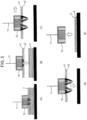
- control device may be configured to perform control in such a way that some of the electromagnetic coils is excited for lifting steel plates, and that at least one of the rest of the electromagnetic coils is excited for conveying the lifted steel plates.
- a steel plate conveying method carried out by using the steel plate lifting apparatus according to any one of claims 4 to 7 is a steel plate conveying method that includes lifting steel plates to be conveyed by exciting some of the electromagnetic coils; and conveying, after the lifting, the lifted steel plates by exciting at least one of the rest of the electromagnetic coils.
- the steel plates are lifted by exciting the innermost one of the electromagnetic coils; and after the lifting, the lifted steel plates are conveyed by exciting the rest of the electromagnetic coils.
- the lifting magnet includes a magnetic flux sensor for measuring the magnetic flux density directly under the magnetic poles
- the magnetic flux penetration depth for steel plates to be lifted can be calculated from the magnetic flux density measured by the magnetic flux sensor, and the attracted state of the steel plates can be determined from the calculated magnetic flux penetration depth.
- a steel plate lifting apparatus calculates, from the magnetic flux density measured by the magnetic flux sensor, the magnetic flux penetration depth for steel plates to be lifted, determines, from the calculated magnetic flux penetration depth, the attracted state of the steel plates, and performs feedback control on a voltage applied to the electromagnetic coil on the basis of the determination. This is advantageous in that the number of steel plates to be lifted can be controlled with high precision, and that the operation of conveying steel plates can be made more efficient.
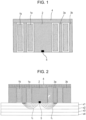
- the lifting magnet includes a plurality of electromagnetic coils 1a and 1b arranged in a nested manner and capable of being independently ON/OFF-controlled and voltage-controlled.
- the lifting magnet includes the first electromagnetic coil 1a on the inner side and the second electromagnetic coil 1b on the outer side (hereinafter, "electromagnetic coil” will be simply referred to as “coil” for convenience in explanation).
- This lifting magnet has a horizontal cross-section, such as that illustrated in Fig. 9 .
- the first coil 1a and the second coil 1b are, for example, ring-shaped exciting coils insulated by being wound many times with an enameled copper wire.
- the two coils 1a and 1b are arranged in a nested manner, with an intermediate pole 3a interposed therebetween.
- the two coils 1a and 1b have different ring diameters.
- the plurality of coils 1a and 1b are concentrically arranged in this example, they simply need to be arranged in a nested manner and do not necessarily need to be concentrically arranged.
- An inner pole 2 formed by, for example, a cylindrical iron core is disposed inside the first coil 1a on the inner side.
- the intermediate pole 3a formed by a ring-shaped iron core is interposed between the first coil 1a and the second coil 1b.
- An outer pole 3b formed by a ring-shaped iron core is disposed outside the second coil 1b.
- a yoke 4 is disposed to be in contact with, and secured to, the upper ends of the inner pole 2, the intermediate pole 3a, and the outer pole 3b.
- gaps between the coils 1a and 1b and the magnetic poles and the yoke 4 are filled with a nonmagnetic material, such as a resin, for securing the coils 1a and 1b in place.
- a nonmagnetic material such as a resin
- the inner pole 2, the intermediate pole 3a, the outer pole 3b, and the yoke 4 are formed of a soft magnetic material, such as mild steel, and some or all of them may constitute an integral structure.
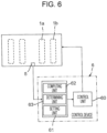
- the lifting magnet of the present embodiment includes a magnetic flux sensor 5 that measures a magnetic flux density of a magnetic pole. From the magnetic flux density measured by the magnetic flux sensor 5, a magnetic flux penetration depth for steel plates to be lifted (or conveyed) can be determined. Since the magnetic flux penetration depth shows the thickness (or number) of steel plates in an attracted state, it is possible to determine whether a desired number of steel plates to be lifted are in an attracted state.
- a steel plate lifting apparatus includes a lifting magnet including the magnetic flux sensor 5, and a control device 6 configured to control the number of steel plates to be lifted on the basis of the magnetic flux density measured by the magnetic flux sensor 5.
- the control device 6 calculates, from a magnetic flux density measured by the magnetic flux sensor, a magnetic flux penetration depth for steel plates to be lifted, determines, from the calculated magnetic flux penetration depth, an attracted state of steel plates, and performs feedback control on a voltage applied to an electromagnetic coil on the basis of the determination.
- the number of steel plates to be lifted can thus be controlled with particularly high precision, and the operation of lifting and conveying the steel plates can be made more efficient.
- the magnetic flux sensor 5 is constituted, for example, by a Hall element or a search coil.
- the magnetic flux sensor 5 of the present embodiment is constituted by a Hall element.
- the magnetic flux sensor 5 may be installed at any position where the magnetic flux density of the magnetic pole can be measured.
- the magnetic flux sensor 5 is installed at the lower end (or at the center of the lower end) of the inner pole 2 to measure the magnetic flux density of the magnetic flux that passes through the inner pole 2.
- the magnetic flux penetration depth can be calculated on the basis of the magnetic flux density of the inner pole 2 measured by the magnetic flux sensor 5.
- a plurality of magnetic flux sensors 5 may be provided at different positions of the magnetic pole (inner pole 2 or/and intermediate pole 3a, outer pole 3b).
- Fig. 4 is a vertical cross-sectional view schematically illustrating another embodiment of the lifting magnet according to the present invention.
- the magnetic flux sensor 5 is constituted by a search coil, which is disposed along the circumferential direction at the lower end of the inner pole 2.
- the magnetic flux sensor 5 is preferably installed in such a way that it can measure the magnetic flux density of the magnetic flux passing through the inner pole 2.
- the magnetic flux density is considered substantially uniform within the lower surface of the inner pole.
- the magnetic flux density is measured by the magnetic flux sensor 5 installed at the center of the lower end of the inner pole 2.
- the magnetic flux sensor 5 is constituted by a search coil as in the case of the embodiment illustrated in Fig. 4
- the amount (or total amount) of magnetic flux on the lower surface of the inner pole is measured by the search coil. Accordingly, an in-plane average value obtained by dividing the measured amount (or total amount) of magnetic flux by the area of the lower surface of the inner pole is determined as the magnetic flux density of the inner pole 2.
- the amount of magnetic flux that can pass in the steel plates can be expressed as ⁇ ⁇ ⁇ I ⁇ t ⁇ B s , where ⁇ I (mm) is an inner pole diameter, t (mm) is the total plate thickness of steel plates to be lifted, and B s (T) is the saturation magnetic flux density of the steel plates.
Landscapes
- Physics & Mathematics (AREA)
- Electromagnetism (AREA)
- Engineering & Computer Science (AREA)
- Mechanical Engineering (AREA)
- Power Engineering (AREA)
- Condensed Matter Physics & Semiconductors (AREA)
- General Physics & Mathematics (AREA)
- Automation & Control Theory (AREA)
- Load-Engaging Elements For Cranes (AREA)
Claims (9)
- Hebemagnet (10), aufweisend:eine Mehrzahl von elektromagnetischen Spulen (1), die in einer verschachtelten Weise angeordnet und dazu ausgestaltet sind, unabhängig AN/AUS-gesteuert und spannungsgesteuert zu werden;einen inneren Pol (2), der innerhalb einer innersten der elektromagnetischen Spulen (1) angeordnet ist;einen Zwischenpol (3a), der zwischen benachbarten elektromagnetischen Spulen (1) angeordnet ist;einen äußeren Pol (3b), der außerhalb einer äußersten der elektromagnetischen Spulen (1) angeordnet ist; undein Joch (4), das in Kontakt mit oberen Enden des inneren Pols (2), des Zwischenpols (3a) und des äußeren Pols (3b) angeordnet ist,dadurch gekennzeichnet, dasseine maximale Menge magnetischen Flusses der innersten der elektromagnetischen Spulen (1) kleiner ist als eine maximale Menge magnetischen Flusses des Rests der elektromagnetischen Spulen (1).
- Hebemagnet (10) gemäß Anspruch 1, ferner aufweisend einen magnetischen Flusssensor (5), der dazu ausgestaltet ist, eine magnetische Flussdichte direkt unter den magnetischen Polen zu messen.
- Hebemagnet (10) nach Anspruch 2, wobei der magnetische Flusssensor (5) an einem unteren Ende des inneren Pols (2) angeordnet ist.
- Stahlplattenhebevorrichtung, aufweisend:den Hebemagnet (10) gemäß einem der Ansprüche 1 bis 3; undeine Steuervorrichtung (6), die dazu ausgestaltet ist, einen Betrieb der Mehrzahl von elektromagnetischen Spulen (1) mittels eines durch den magnetischen Flusssensor (5) erzeugten Messergebnisses zu steuern.
- Stahlplattenhebevorrichtung nach Anspruch 4, wobei die Steuervorrichtung (6) dazu ausgestaltet ist,eine Steuerung in einer solchen Weise durchzuführen, dass eine Spannung, die einer festgelegten Anzahl von zu hebenden Stahlplatten (x) entspricht, auf die elektromagnetischen Spulen (1) aufgebracht wird;ausgehend von der durch den magnetischen Flusssensor (5) gemessenen magnetischen Flussdichte eine Eindringtiefe des magnetischen Flusses für die zu hebenden Stahlplatten (x) zu berechnen;ausgehend von der berechneten Eindringtiefe des magnetischen Flusses zu bestimmen, ob die Anzahl von zu hebenden Stahlplatten (x) zu der festgelegten Anzahl passt; unddie Spannung zu steuern, die auf die elektromagnetischen Spulen (1) auf der Grundlage der Bestimmung aufgebracht wird.
- Stahlplattenhebevorrichtung nach Anspruch 5, wobei die Steuervorrichtung (6) zum Heben von Stahlplatten (x) dazu ausgestaltet ist, eine Spannung zu steuern, die auf die innerste der elektromagnetischen Spulen (1) aufgebracht wird, um die Anzahl von zu hebenden Stahlplatten (x) zu steuern.
- Stahlplattenhebevorrichtung nach einem der Ansprüche 4 bis 6, wobei die Steuervorrichtung (6) dazu ausgestaltet ist, eine Steuerung in einer solchen Weise durchzuführen, dass irgendeine der elektromagnetischen Spulen (1) zum Heben von Stahlplatten (x) angeregt wird und dass zumindest eine der übrigen der elektromagnetischen Spulen (1) zum Befördern der angehobenen Stahlplatten angeregt wird.
- Stahlplattenbeförderungsverfahren, das durch Verwenden der Stahlplattenhebevorrichtung nach einem der Ansprüche 4 bis 7 ausgeführt wird, wobei das Stahlplattenbeförderungsverfahren umfasst:Heben von zu befördernden Stahlplatten (x) durch Anregen von einigen der elektromagnetischen Spulen (1); undBefördern der gehobenen Stahlplatten (x) nach dem Heben durch Anregen von zumindest einer der übrigen der elektromagnetischen Spulen (1).
- Stahlplattenbeförderungsverfahren nach Anspruch 8, wobei die Stahlplatten (x) durch Anregen der innersten der elektromagnetischen Spulen (1) angehoben werden; und
die gehobenen Stahlplatten (x) nach dem Heben durch Anregen der übrigen der elektromagnetischen Spulen (1) befördert werden.
Applications Claiming Priority (2)
| Application Number | Priority Date | Filing Date | Title |
|---|---|---|---|
| JP2020091097 | 2020-05-26 | ||
| PCT/JP2021/019144 WO2021241392A1 (ja) | 2020-05-26 | 2021-05-20 | リフティングマグネット及び鋼板の吊り上げ装置、並びに鋼板の搬送方法 |
Publications (3)
| Publication Number | Publication Date |
|---|---|
| EP4122866A1 EP4122866A1 (de) | 2023-01-25 |
| EP4122866A4 EP4122866A4 (de) | 2023-09-27 |
| EP4122866B1 true EP4122866B1 (de) | 2025-07-02 |
Family
ID=78744472
Family Applications (1)
| Application Number | Title | Priority Date | Filing Date |
|---|---|---|---|
| EP21812401.4A Active EP4122866B1 (de) | 2020-05-26 | 2021-05-20 | Hebemagnet, stahlblechhebevorrichtung und stahlblechförderverfahren |
Country Status (7)
| Country | Link |
|---|---|
| US (1) | US20230174347A1 (de) |
| EP (1) | EP4122866B1 (de) |
| JP (1) | JP7287479B2 (de) |
| KR (1) | KR102863670B1 (de) |
| CN (1) | CN115551797A (de) |
| TW (1) | TWI843948B (de) |
| WO (1) | WO2021241392A1 (de) |
Family Cites Families (15)
| Publication number | Priority date | Publication date | Assignee | Title |
|---|---|---|---|---|
| GB1187557A (en) * | 1968-05-14 | 1970-04-08 | Nielsen & Son Maskinfab As H | A Lifting Magnet for Sheet-Formed Objects of Magnetisable Material |
| JPS5176564A (ja) * | 1974-12-27 | 1976-07-02 | Hitachi Ltd | Tsuriagedenjishaku |
| JPS6362479U (de) * | 1986-10-13 | 1988-04-25 | ||
| JPH06104548B2 (ja) | 1989-05-11 | 1994-12-21 | 新日本製鐵株式会社 | リフティングマグネットクレーン装置 |
| JPH06227785A (ja) * | 1993-02-02 | 1994-08-16 | Hitachi Kiden Kogyo Ltd | リフティングマグネット装置 |
| GB9613061D0 (en) * | 1995-09-02 | 1996-08-28 | Magnetic Patent Holdings Ltd | Magnetic suspension system |
| JP2000226179A (ja) | 1999-02-04 | 2000-08-15 | Mitsubishi Plastics Ind Ltd | 吊上げ装置 |
| JP2007217119A (ja) * | 2006-02-16 | 2007-08-30 | Sumitomo Heavy Ind Ltd | リフティングマグネット |
| JP2008265997A (ja) * | 2007-04-24 | 2008-11-06 | Sumitomo Heavy Ind Ltd | リフティングマグネット駆動回路及びリフティングマグネット装置 |
| KR20120073164A (ko) * | 2012-05-14 | 2012-07-04 | 최규철 | 후판 이송시스템 |
| TWM486643U (zh) * | 2014-06-12 | 2014-09-21 | China Steel Corp | 磁力可調吸盤電控系統 |
| CN204342244U (zh) * | 2014-09-11 | 2015-05-20 | 杨曙强 | 卸船机上吊运钢板的安全型矩形电磁吸盘 |
| US11097401B2 (en) * | 2017-04-27 | 2021-08-24 | Magswitch Technology Worldwide Pty Ltd. | Magnetic coupling device with at least one of a sensor arrangement and a degauss capability |
| WO2019107504A1 (ja) * | 2017-11-29 | 2019-06-06 | Jfeスチール株式会社 | リフティングマグネット用取り付け磁極、鋼材吊上げ用磁極付リフティングマグネット、鋼材の搬送方法、並びに鋼板の製造方法 |
| DE102018101945B4 (de) * | 2018-01-29 | 2022-11-10 | Tremba GmbH | Vorrichtung, System und Verfahren zum selektiven magnetischen Abheben mindestens einer Metallplatte von einem Stapel |
-
2021
- 2021-05-20 EP EP21812401.4A patent/EP4122866B1/de active Active
- 2021-05-20 KR KR1020227039417A patent/KR102863670B1/ko active Active
- 2021-05-20 WO PCT/JP2021/019144 patent/WO2021241392A1/ja not_active Ceased
- 2021-05-20 US US17/926,016 patent/US20230174347A1/en active Pending
- 2021-05-20 JP JP2021549983A patent/JP7287479B2/ja active Active
- 2021-05-20 CN CN202180034951.9A patent/CN115551797A/zh active Pending
- 2021-05-24 TW TW110118664A patent/TWI843948B/zh active
Also Published As
| Publication number | Publication date |
|---|---|
| BR112022022870A2 (pt) | 2022-12-20 |
| TW202202436A (zh) | 2022-01-16 |
| EP4122866A4 (de) | 2023-09-27 |
| JPWO2021241392A1 (de) | 2021-12-02 |
| US20230174347A1 (en) | 2023-06-08 |
| EP4122866A1 (de) | 2023-01-25 |
| WO2021241392A1 (ja) | 2021-12-02 |
| CN115551797A (zh) | 2022-12-30 |
| KR20220166349A (ko) | 2022-12-16 |
| KR102863670B1 (ko) | 2025-09-23 |
| JP7287479B2 (ja) | 2023-06-06 |
| TWI843948B (zh) | 2024-06-01 |
Similar Documents
| Publication | Publication Date | Title |
|---|---|---|
| EP3718946B1 (de) | Befestigungsmagnetpol für hubmagnet, hubmagnet mit magnetpol zum heben von stahlmaterial, verfahren zum fördern von stahlmaterial und verfahren zur herstellung von stahlblech | |
| EP4122866B1 (de) | Hebemagnet, stahlblechhebevorrichtung und stahlblechförderverfahren | |
| EP4257532A1 (de) | Stahlblechhebeverfahren mit hebemagnet, hebemagnet und stahlblechherstellungsverfahren mit hebemagnet | |
| KR20120073164A (ko) | 후판 이송시스템 | |
| US3983961A (en) | Transducer for servomechanisms | |
| JPH06104548B2 (ja) | リフティングマグネットクレーン装置 | |
| JP2004345774A (ja) | リフティングマグネットクレーン装置 | |
| JPH0977452A (ja) | 吊上電磁石を用いたクレーンの自動運転方法 | |
| BR112022022870B1 (pt) | Ímã de elevação e aparelho de elevação de chapa de aço e método de transporte de chapa de aço | |
| JP7715141B2 (ja) | 鋼板の吊上方法及び吊上装置、並びに、鋼板の製造方法 | |
| KR101209158B1 (ko) | 후판 이송시스템 | |
| JPH06278127A (ja) | スライシングマシン | |
| JPH10157965A (ja) | リフマグクレーン | |
| RU2184063C2 (ru) | Электромагнитный листоукладчик | |
| JP2001006862A (ja) | 電磁誘導加熱装置 | |
| JP2503309B2 (ja) | 鋼板吊上用電磁石装置 | |
| JP2841578B2 (ja) | 鉄損値測定データの校正方法及び校正装置 | |
| JPH02295890A (ja) | リフティングマグネットクレーン装置 | |
| JPS61212006A (ja) | リフテイングマグネツト装置 | |
| JPH0567519A (ja) | 電磁石装置 | |
| JPH0714792B2 (ja) | 鋼板吊枚数選別制御方法 | |
| JPH03128890A (ja) | 鋼板吊枚数選別制御方法 | |
| JPS6186357A (ja) | マグネツトロ−ラの励磁方法 |
Legal Events
| Date | Code | Title | Description |
|---|---|---|---|
| STAA | Information on the status of an ep patent application or granted ep patent |
Free format text: STATUS: THE INTERNATIONAL PUBLICATION HAS BEEN MADE |
|
| PUAI | Public reference made under article 153(3) epc to a published international application that has entered the european phase |
Free format text: ORIGINAL CODE: 0009012 |
|
| STAA | Information on the status of an ep patent application or granted ep patent |
Free format text: STATUS: REQUEST FOR EXAMINATION WAS MADE |
|
| 17P | Request for examination filed |
Effective date: 20221017 |
|
| AK | Designated contracting states |
Kind code of ref document: A1 Designated state(s): AL AT BE BG CH CY CZ DE DK EE ES FI FR GB GR HR HU IE IS IT LI LT LU LV MC MK MT NL NO PL PT RO RS SE SI SK SM TR |
|
| DAV | Request for validation of the european patent (deleted) | ||
| DAX | Request for extension of the european patent (deleted) | ||
| A4 | Supplementary search report drawn up and despatched |
Effective date: 20230825 |
|
| RIC1 | Information provided on ipc code assigned before grant |
Ipc: B66C 1/06 20060101AFI20230821BHEP |
|
| GRAP | Despatch of communication of intention to grant a patent |
Free format text: ORIGINAL CODE: EPIDOSNIGR1 |
|
| STAA | Information on the status of an ep patent application or granted ep patent |
Free format text: STATUS: GRANT OF PATENT IS INTENDED |
|
| INTG | Intention to grant announced |
Effective date: 20241108 |
|
| GRAJ | Information related to disapproval of communication of intention to grant by the applicant or resumption of examination proceedings by the epo deleted |
Free format text: ORIGINAL CODE: EPIDOSDIGR1 |
|
| STAA | Information on the status of an ep patent application or granted ep patent |
Free format text: STATUS: REQUEST FOR EXAMINATION WAS MADE |
|
| GRAP | Despatch of communication of intention to grant a patent |
Free format text: ORIGINAL CODE: EPIDOSNIGR1 |
|
| STAA | Information on the status of an ep patent application or granted ep patent |
Free format text: STATUS: GRANT OF PATENT IS INTENDED |
|
| INTC | Intention to grant announced (deleted) | ||
| INTG | Intention to grant announced |
Effective date: 20250207 |
|
| GRAS | Grant fee paid |
Free format text: ORIGINAL CODE: EPIDOSNIGR3 |
|
| GRAA | (expected) grant |
Free format text: ORIGINAL CODE: 0009210 |
|
| STAA | Information on the status of an ep patent application or granted ep patent |
Free format text: STATUS: THE PATENT HAS BEEN GRANTED |
|
| AK | Designated contracting states |
Kind code of ref document: B1 Designated state(s): AL AT BE BG CH CY CZ DE DK EE ES FI FR GB GR HR HU IE IS IT LI LT LU LV MC MK MT NL NO PL PT RO RS SE SI SK SM TR |
|
| REG | Reference to a national code |
Ref country code: GB Ref legal event code: FG4D |
|
| REG | Reference to a national code |
Ref country code: CH Ref legal event code: EP |
|
| REG | Reference to a national code |
Ref country code: DE Ref legal event code: R096 Ref document number: 602021033493 Country of ref document: DE |
|
| REG | Reference to a national code |
Ref country code: IE Ref legal event code: FG4D |
|
| REG | Reference to a national code |
Ref country code: NL Ref legal event code: MP Effective date: 20250702 |
|
| PG25 | Lapsed in a contracting state [announced via postgrant information from national office to epo] |
Ref country code: PT Free format text: LAPSE BECAUSE OF FAILURE TO SUBMIT A TRANSLATION OF THE DESCRIPTION OR TO PAY THE FEE WITHIN THE PRESCRIBED TIME-LIMIT Effective date: 20251103 |
|
| PG25 | Lapsed in a contracting state [announced via postgrant information from national office to epo] |
Ref country code: NL Free format text: LAPSE BECAUSE OF FAILURE TO SUBMIT A TRANSLATION OF THE DESCRIPTION OR TO PAY THE FEE WITHIN THE PRESCRIBED TIME-LIMIT Effective date: 20250702 |
|
| REG | Reference to a national code |
Ref country code: AT Ref legal event code: MK05 Ref document number: 1809083 Country of ref document: AT Kind code of ref document: T Effective date: 20250702 |
|
| PG25 | Lapsed in a contracting state [announced via postgrant information from national office to epo] |
Ref country code: IS Free format text: LAPSE BECAUSE OF FAILURE TO SUBMIT A TRANSLATION OF THE DESCRIPTION OR TO PAY THE FEE WITHIN THE PRESCRIBED TIME-LIMIT Effective date: 20251102 |
|
| PG25 | Lapsed in a contracting state [announced via postgrant information from national office to epo] |
Ref country code: NO Free format text: LAPSE BECAUSE OF FAILURE TO SUBMIT A TRANSLATION OF THE DESCRIPTION OR TO PAY THE FEE WITHIN THE PRESCRIBED TIME-LIMIT Effective date: 20251002 |
|
| REG | Reference to a national code |
Ref country code: LT Ref legal event code: MG9D |
|
| PG25 | Lapsed in a contracting state [announced via postgrant information from national office to epo] |
Ref country code: AT Free format text: LAPSE BECAUSE OF FAILURE TO SUBMIT A TRANSLATION OF THE DESCRIPTION OR TO PAY THE FEE WITHIN THE PRESCRIBED TIME-LIMIT Effective date: 20250702 |
|
| PG25 | Lapsed in a contracting state [announced via postgrant information from national office to epo] |
Ref country code: FI Free format text: LAPSE BECAUSE OF FAILURE TO SUBMIT A TRANSLATION OF THE DESCRIPTION OR TO PAY THE FEE WITHIN THE PRESCRIBED TIME-LIMIT Effective date: 20250702 |
|
| PG25 | Lapsed in a contracting state [announced via postgrant information from national office to epo] |
Ref country code: HR Free format text: LAPSE BECAUSE OF FAILURE TO SUBMIT A TRANSLATION OF THE DESCRIPTION OR TO PAY THE FEE WITHIN THE PRESCRIBED TIME-LIMIT Effective date: 20250702 |
|
| PG25 | Lapsed in a contracting state [announced via postgrant information from national office to epo] |
Ref country code: GR Free format text: LAPSE BECAUSE OF FAILURE TO SUBMIT A TRANSLATION OF THE DESCRIPTION OR TO PAY THE FEE WITHIN THE PRESCRIBED TIME-LIMIT Effective date: 20251003 |
|
| PG25 | Lapsed in a contracting state [announced via postgrant information from national office to epo] |
Ref country code: SE Free format text: LAPSE BECAUSE OF FAILURE TO SUBMIT A TRANSLATION OF THE DESCRIPTION OR TO PAY THE FEE WITHIN THE PRESCRIBED TIME-LIMIT Effective date: 20250702 Ref country code: CZ Free format text: LAPSE BECAUSE OF FAILURE TO SUBMIT A TRANSLATION OF THE DESCRIPTION OR TO PAY THE FEE WITHIN THE PRESCRIBED TIME-LIMIT Effective date: 20250702 |
|
| PG25 | Lapsed in a contracting state [announced via postgrant information from national office to epo] |
Ref country code: LV Free format text: LAPSE BECAUSE OF FAILURE TO SUBMIT A TRANSLATION OF THE DESCRIPTION OR TO PAY THE FEE WITHIN THE PRESCRIBED TIME-LIMIT Effective date: 20250702 |
|
| PG25 | Lapsed in a contracting state [announced via postgrant information from national office to epo] |
Ref country code: BG Free format text: LAPSE BECAUSE OF FAILURE TO SUBMIT A TRANSLATION OF THE DESCRIPTION OR TO PAY THE FEE WITHIN THE PRESCRIBED TIME-LIMIT Effective date: 20250702 Ref country code: PL Free format text: LAPSE BECAUSE OF FAILURE TO SUBMIT A TRANSLATION OF THE DESCRIPTION OR TO PAY THE FEE WITHIN THE PRESCRIBED TIME-LIMIT Effective date: 20250702 |
|
| PG25 | Lapsed in a contracting state [announced via postgrant information from national office to epo] |
Ref country code: RS Free format text: LAPSE BECAUSE OF FAILURE TO SUBMIT A TRANSLATION OF THE DESCRIPTION OR TO PAY THE FEE WITHIN THE PRESCRIBED TIME-LIMIT Effective date: 20251002 |
|
| PG25 | Lapsed in a contracting state [announced via postgrant information from national office to epo] |
Ref country code: ES Free format text: LAPSE BECAUSE OF FAILURE TO SUBMIT A TRANSLATION OF THE DESCRIPTION OR TO PAY THE FEE WITHIN THE PRESCRIBED TIME-LIMIT Effective date: 20250702 |
|
| PG25 | Lapsed in a contracting state [announced via postgrant information from national office to epo] |
Ref country code: SM Free format text: LAPSE BECAUSE OF FAILURE TO SUBMIT A TRANSLATION OF THE DESCRIPTION OR TO PAY THE FEE WITHIN THE PRESCRIBED TIME-LIMIT Effective date: 20250702 |
|
| PG25 | Lapsed in a contracting state [announced via postgrant information from national office to epo] |
Ref country code: DK Free format text: LAPSE BECAUSE OF FAILURE TO SUBMIT A TRANSLATION OF THE DESCRIPTION OR TO PAY THE FEE WITHIN THE PRESCRIBED TIME-LIMIT Effective date: 20250702 |
|
| PG25 | Lapsed in a contracting state [announced via postgrant information from national office to epo] |
Ref country code: IT Free format text: LAPSE BECAUSE OF FAILURE TO SUBMIT A TRANSLATION OF THE DESCRIPTION OR TO PAY THE FEE WITHIN THE PRESCRIBED TIME-LIMIT Effective date: 20250702 |