EP3718946B1 - Befestigungsmagnetpol für hubmagnet, hubmagnet mit magnetpol zum heben von stahlmaterial, verfahren zum fördern von stahlmaterial und verfahren zur herstellung von stahlblech - Google Patents
Befestigungsmagnetpol für hubmagnet, hubmagnet mit magnetpol zum heben von stahlmaterial, verfahren zum fördern von stahlmaterial und verfahren zur herstellung von stahlblech Download PDFInfo
- Publication number
- EP3718946B1 EP3718946B1 EP18883651.4A EP18883651A EP3718946B1 EP 3718946 B1 EP3718946 B1 EP 3718946B1 EP 18883651 A EP18883651 A EP 18883651A EP 3718946 B1 EP3718946 B1 EP 3718946B1
- Authority
- EP
- European Patent Office
- Prior art keywords
- lifting
- magnetic pole
- magnetic
- pole
- magnet
- Prior art date
- Legal status (The legal status is an assumption and is not a legal conclusion. Google has not performed a legal analysis and makes no representation as to the accuracy of the status listed.)
- Active
Links
Images


Classifications
-
- B—PERFORMING OPERATIONS; TRANSPORTING
- B66—HOISTING; LIFTING; HAULING
- B66C—CRANES; LOAD-ENGAGING ELEMENTS OR DEVICES FOR CRANES, CAPSTANS, WINCHES, OR TACKLES
- B66C1/00—Load-engaging elements or devices attached to lifting or lowering gear of cranes or adapted for connection therewith for transmitting lifting forces to articles or groups of articles
- B66C1/04—Load-engaging elements or devices attached to lifting or lowering gear of cranes or adapted for connection therewith for transmitting lifting forces to articles or groups of articles by magnetic means
- B66C1/06—Load-engaging elements or devices attached to lifting or lowering gear of cranes or adapted for connection therewith for transmitting lifting forces to articles or groups of articles by magnetic means electromagnetic
-
- H—ELECTRICITY
- H01—ELECTRIC ELEMENTS
- H01F—MAGNETS; INDUCTANCES; TRANSFORMERS; SELECTION OF MATERIALS FOR THEIR MAGNETIC PROPERTIES
- H01F3/00—Cores, Yokes, or armatures
- H01F3/10—Composite arrangements of magnetic circuits
-
- H—ELECTRICITY
- H01—ELECTRIC ELEMENTS
- H01F—MAGNETS; INDUCTANCES; TRANSFORMERS; SELECTION OF MATERIALS FOR THEIR MAGNETIC PROPERTIES
- H01F7/00—Magnets
- H01F7/06—Electromagnets; Actuators including electromagnets
- H01F7/08—Electromagnets; Actuators including electromagnets with armatures
- H01F7/13—Electromagnets; Actuators including electromagnets with armatures characterised by pulling-force characteristics
-
- H—ELECTRICITY
- H01—ELECTRIC ELEMENTS
- H01F—MAGNETS; INDUCTANCES; TRANSFORMERS; SELECTION OF MATERIALS FOR THEIR MAGNETIC PROPERTIES
- H01F7/00—Magnets
- H01F7/06—Electromagnets; Actuators including electromagnets
- H01F7/20—Electromagnets; Actuators including electromagnets without armatures
- H01F7/206—Electromagnets for lifting, handling or transporting of magnetic pieces or material
-
- H—ELECTRICITY
- H01—ELECTRIC ELEMENTS
- H01F—MAGNETS; INDUCTANCES; TRANSFORMERS; SELECTION OF MATERIALS FOR THEIR MAGNETIC PROPERTIES
- H01F7/00—Magnets
- H01F7/06—Electromagnets; Actuators including electromagnets
- H01F7/08—Electromagnets; Actuators including electromagnets with armatures
- H01F7/18—Circuit arrangements for obtaining desired operating characteristics, e.g. for slow operation, for sequential energisation of windings, for high-speed energisation of windings
Definitions
- the present invention relates to a lifting-magnet attachment magnetic pole unit used to lift and convey steel materials in such places as steel works and steel plate processing plants, a steel-lifting magnetic-pole-equipped lifting magnet, a steel material conveying method, and a steel plate manufacturing method.
- Steel materials are lifted and conveyed in a plate mill of a steel works.
- the process carried out in the plate mill is roughly divided into two steps: a rolling step which involves rolling out a block of steel into a steel plate of a desired thickness; and a finishing step which involves cutting into a shipping size, removing burrs from edges, repairing surface flaws, and inspecting internal flaws.
- a rolling step which involves rolling out a block of steel into a steel plate of a desired thickness
- a finishing step which involves cutting into a shipping size, removing burrs from edges, repairing surface flaws, and inspecting internal flaws.
- steel plates are stored in stacks of several to more than a dozen pieces for space saving.
- steel plates may be simply referred to as steel materials.
- the finishing step and the shipment or transfer operation involve lifting and moving only one or more (e.g., two or three) intended pieces of plate from the storage area using an electromagnetic lifting magnet attached to a crane.
- an electromagnetic lifting magnet attached to a crane typically used in the steel works leads to attracting unnecessary steel materials stacked underneath the steel material to be lifted.
- the unnecessary steel materials attracted here need to be dropped by controlling the amount of current in the lifting magnet or by turning on and off the power, so as to adjust the number of plates to be attracted.
- the operation may need to be redone many times and this leads to significant loss of work efficiency.
- the operation involving adjusting the number of plates to be attracted, as described above has been a significant hindrance to automating the crane operation.
- Patent Literature 1 and Patent Literature 4 each describe a method that controls lifting force by controlling current applied to a coil of the lifting magnet.
- Patent Literature 2 describes a technique that uses a lifting magnet having a plurality of small permanent magnets.
- Patent Literature 3 describes a technique that uses a lifting magnet having a plurality of small electromagnetic magnets that are excited independently.
- Patent Literature 5 relates to a lifting electromagnet in which the contact area of a magnetic pole is variably controlled by vertical movement of a movable magnetic pole.
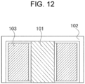
- Fig. 12 is a cross-sectional view illustrating an internal structure of a typical electromagnetic lifting magnet.
- the typical electromagnetic lifting magnet (hereinafter, a typical lifting magnet will be simply referred to as a lifting magnet) has an internal coil 103 with a diameter of one hundred to several hundred mm.
- An iron core (inner pole) 101 is mounted inside the coil 103 and a yoke (outer pole) 102 for transmitting a magnetic field is mounted outside the coil 103.
- a magnetic field circuit is formed and the steel material is attracted to the lifting magnet.
- magnetic flux saturation occurs in the uppermost piece of steel materials if the steel materials have a relatively thin plate thickness of 20 mm or less. Then, a plurality of plates are simultaneously attracted to the lifting magnet and this leads to a loss of efficiency in conveying steel materials and poses a significant hindrance to automating the crane operation.
- controlling the number of plates attracted to the lifting magnet requires controlling the penetration depth to which the magnetic flux reaches in stacked steel materials, in accordance with the plate thickness of the steel materials and the number of steel materials to be lifted.
- Patent Literature 1 For the problem of magnetic flux saturation in the uppermost piece of steel material, the technique described in Patent Literature 1 is also effective, which controls current to be applied.
- the technique described in Patent Literature 1 is also effective, which controls current to be applied.
- Sensing of the plate thickness of steel materials to be lifted is also required. This requires sensors and related equipment and leads to increased initial introduction costs.
- Patent Literature 2 uses permanent magnets, with which producing large attracting force is typically more difficult than with electromagnetic lifting magnets. Therefore, it is difficult to apply this technique to a lifting magnet used to transport steel materials that weigh several tons (t) to several tens of tons (t) in the plate mill of the steel works.
- Patent Literature 3 requires a smaller coil to be mounted on each of small magnetic poles.
- the small coil needs to be designed such that its attracting force is equivalent to that of a large coil.
- the attracting force of a coil can be determined roughly by (attracting area) ⁇ (square of the number of coil turns) ⁇ (square of current). If the size of the coil is reduced by reducing the number of turns without changing the diameter of the coil copper wire, it is necessary to increase either the attracting area or the current value. Increasing the attracting area increases the weight of the lifting magnet and this leads to an increase in load on the crane.
- Patent Literature 4 presents a method that controls the output of magnetic flux by controlling current in the coil and changes the penetration depth of the magnetic flux.
- a lifting magnet typically used in the plate mill of the steel works is designed such that a large magnetic pole can apply a large amount of magnetic flux to steel materials, and the maximum penetration depth of magnetic flux is large, as described below. Therefore, the penetration depth of magnetic flux changes significantly in response to a small change in current. If steel materials to be lifted are of a thin plate thickness, the number of steel materials to be lifted cannot be properly controlled because of gaps created by warpage or errors of the magnetic flux sensor. Therefore, it is difficult to apply the technique of Patent Literature 4 to a lifting magnet used to transport steel materials weighing several tons (t) to several tens of tons (t) in the plate mill of the steel works.
- Patent Literature 3 is a method that changes the penetration depth of magnetic flux by varying the size of an electromagnet.
- To exert attracting force equivalent to that when one large magnetic pole is attached to a lifting magnet it is necessary to make the total area of magnetic poles and the output magnetic flux density substantially the same as those in the electromagnet having a large coil.
- To maintain the total area of magnetic poles it is necessary to attach many small electromagnets to the lifting magnet.
- An object of the present invention is to provide a lifting-magnet attachment magnetic pole unit, a steel-lifting magnetic-pole-equipped lifting magnet, a steel material conveying method, and a steel plate manufacturing method with which only one or a desired number of steel materials can be held.
- lifting-magnet attachment magnetic pole unit of the present invention refers to one that is attached to a lifting magnet and serves as part of a magnetic field circuit of the lifting magnet.
- the present inventors examined techniques for lifting only a desired one piece of steel materials (e.g., steel plates) stacked in layers. The present inventors then found out that by applying a magnetic flux from the inner pole of the lifting magnet to steel materials in a dispersed form without reducing the amount of magnetic flux, the magnetic flux density in the uppermost piece of steel material was reduced and the occurrence of magnetic flux saturation was avoided. The present inventors also found out that since the amount of magnetic flux applied to steel materials was not changed, there was no reduction in attracting force and the uppermost piece of steel material was strongly attracted.
- the present inventors examined techniques for lifting only some (e.g., two or three) desired pieces of steel materials (e.g., steel plates) stacked in layers. The present inventors then found out that by changing the magnetic field circuit, it was possible to change the maximum penetration depth of magnetic flux and control the number of steel materials to be lifted even if the steel materials were of a thin plate thickness.
- the present invention is based on these findings and is summarized as follows.
- the present invention can prevent the occurrence of magnetic flux saturation in the uppermost piece of steel materials stacked in layers. Therefore, even when the steel materials are of a plate thickness of 20 mm or less, only the uppermost piece of those stacked in layers can be easily lifted with the magnetic-pole-equipped lifting magnet. Additionally, since the entire magnetic flux produced in the coil can be used to lift the steel material at the top, larger lifting force can be exerted with the same power consumption as a typical lifting magnet.
- the present invention can change the maximum penetration depth of magnetic flux to a desired value by changing the magnetic field circuit.
- the number of steel materials to be lifted can be controlled with high accuracy.
- a lifting-magnet attachment magnetic pole unit is a lifting-magnet attachment magnetic pole unit for a lifting magnet used to lift and convey a steel material with magnetic force.
- the lifting-magnet attachment magnetic pole unit includes a first split magnetic pole that is in contact with an iron core of the lifting magnet and has a branched structure, and a second split magnetic pole that is in contact with a yoke of the lifting magnet and has a branched structure.
- the first and second split magnetic poles are alternately arranged.
- the dimensions of the first split magnetic pole may satisfy Inequality (1) described below.
- the distance between the first and second split magnetic poles alternately arranged may be 30 mm or less.
- the first and second split magnetic poles may each have a plate thickness of 20 mm or less.
- a steel-lifting magnetic-pole-equipped lifting magnet is a magnetic-pole-equipped lifting magnet used to lift and convey a steel material with magnetic force.
- the steel-lifting magnetic-pole-equipped lifting magnet includes the iron core and the yoke disposed opposite each other, with a coil interposed therebetween, the first split magnetic pole in contact with the iron core and having a branched structure, and the second split magnetic pole in contact with the yoke and having a branched structure.
- the first and second split magnetic poles are alternately arranged.
- the dimensions of the first split magnetic pole may satisfy Inequality (1) described below.
- the distance between the first and second split magnetic poles alternately arranged may be 30 mm or less.
- the first and second split magnetic poles may each have a plate thickness of 20 mm or less.
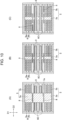
- Fig. 1 is a diagram illustrating how magnetic flux flows in steel materials lifted by a typical lifting magnet (which is an electromagnetic lifting magnet here). Specifically, Fig. 1(A) is a plan view of the steel materials lifted using one lifting magnet, as viewed from above, and Fig. 1(B) is a side cross-sectional view of the steel materials (or cross-sectional view taken along line X-X' in Fig. 1(A) ).
- Fig. 2 is a diagram illustrating how magnetic flux flows in steel materials lifted by smaller lifting magnets into which the lifting magnet described above is divided. Specifically, Fig. 2(A) is a plan view of the steel materials lifted using four separate smaller lifting magnets, and Fig.
- FIG. 2(B) is a side cross-sectional view of the steel materials (or cross-sectional view taken along line Y-Y' in Fig. 2(A) ).
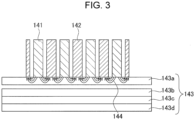
- Fig. 3 is a side cross-sectional view of the steel materials and the lifting magnets, with the steel materials being in a lifted state. Note that arrows in the drawings indicate how magnetic flux flows.
- the lifting magnets (electromagnetic lifting magnets) illustrated in Figs. 2 and 3 have the same structure as that illustrated in Fig. 1 .
- the first embodiment of the present invention where only the uppermost piece of steel material can be easily lifted, is completed by solving the problem of magnetic flux saturation in the uppermost piece of steel material.
- the reason for saturation of magnetic flux in the uppermost piece of steel material will now be described with reference to Figs. 1 and 2 .
- a typical electromagnetic lifting magnet has an internal coil with a diameter of one hundred to several hundred mm.
- An iron core (inner pole) is mounted inside the coil, and a yoke (outer pole) for transmitting a magnetic field is mounted outside the coil.
- a magnetic flux applied from an iron core 111 is diffused from the bottom of the inner pole 111 and travels toward the bottom of a yoke 112 (outer pole).
- a region directly below the outer periphery of the inner pole 111 is a neck portion 113 of the magnetic flux diffusion, that is, a portion where the magnetic flux density is highest in the steel material.
- the inner pole 111 measuring 2a long ⁇ 2a wide is used, and the neck portion 113 has a cross-sectional area of (perimeter of inner pole 111) ⁇ (plate thickness of steel material), that is, 8a ⁇ (plate thickness of steel material).
- a magnetic flux 134 diffused from the inner pole 111 toward the outer pole 112 is large in amount in the neck portion 113.
- the magnetic flux 134 reaches not only a steel material 133a at the top, but also two pieces of steel material 133b and 133c underneath.
- the present inventors focused on the correlation between the size of the neck portion 113 and the magnetic flux density and carried out further studies. The present inventors then found out that reducing the size of the inner pole was effective in reducing the magnetic flux density. Inner poles with a smaller size are illustrated in Fig. 2 .
- a magnetic flux applied from each iron core 121 is diffused from the bottom of the inner pole 121 and travels toward the bottom of a yoke 122 (outer pole) located outside the inner pole 121.
- a region directly below the outer periphery of each inner pole 121 is a neck portion 123 of the magnetic flux diffusion, that is, a portion where the magnetic flux density is highest in the steel material.
- the magnetic flux 144 reaches only a steel material 143a at the top and a steel material 143b underneath.
- a portion (neck portion) where the magnetic flux density is highest in the steel material is divided into a plurality of neck portions 123, which have a larger total cross-sectional area.
- the neck portions 123 thus have a lower magnetic flux density, and this reduces the occurrence of magnetic flux saturation in the uppermost piece of steel material.
- the present inventors carried out further studies to solve the issues resulting from size reduction of the inner pole.
- a large amount of magnetic flux 134 is diffused from the inner pole 111 toward the outer pole 112 and magnetic flux saturation occurs in the steel material 133a at the top.
- the magnetic flux 134 then reaches the underneath steel materials 133b and 133c.
- Fig. 1(B) when, as illustrated in Fig.
- a plurality of smaller split inner poles 141 and outer poles 142 are used to lift the uppermost piece of the steel materials 143a to 143d stacked in layers, the magnetic flux 144 diffused from each inner pole 141 to adjacent ones of the outer poles 142 is limited in amount and magnetic flux saturation does not occur in the steel material 143a at the top. The magnetic flux 144 does not reach the underneath steel materials 143b to 143d.
- the present inventors thus found out that when a magnetic flux was produced by one large coil and input to a steel material by branched inner and outer poles, a magnetic flux diffusion effect was achieved and the problems described above were solved.
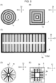
- FIG. 4 schematically illustrates an exemplary lifting-magnet attachment magnetic pole unit used in the first embodiment of the present invention.
- Fig. 5 schematically illustrates other cross-sectional shapes of the lifting-magnet attachment magnetic pole unit.
- Fig. 4(A) and Figs. 5(A) to 5(E) each illustrate a lifting-magnet attachment magnetic pole unit, as viewed from the underside, and
- Fig. 4(B) is a cross-sectional view taken along line C-C' in Fig. 4(A) .
- directions D1 and D2 indicated by two-way arrows are parallel to the steel material surface, whereas direction D3 is perpendicular to the steel material surface.
- a lifting-magnet attachment magnetic pole unit used in an apparatus for conveying steel materials includes at least a first split magnetic pole 5 and a second split magnetic pole 6.
- the first split magnetic pole 5 includes a first shaft 5a in contact with an iron core (inner pole) of a typical lifting magnet, and a plurality of first branches 5b configured to branch off the first shaft 5a.
- the second split magnetic pole 6 includes a second shaft 6a in contact with a yoke (outer pole) of the typical lifting magnet, and a plurality of second branches 6b configured to branch off the second shaft 6a.
- the first and second split magnetic poles 5 and 6 are configured to allow the first and second branches 5b and 6b to be alternately arranged.
- first and second branches 5b and 6b are alternately arranged, with non-magnetic bodies or spaces each interposed between adjacent ones of the first and second branches 5b and 6b.
- Figs. 4(A) and 4(B) illustrate a configuration where the first and second branches 5b and 6b are alternately arranged, with spaces each interposed between adjacent ones of the first and second branches 5b and 6b.
- a distance X 1 between adjacent ones of the first and second branches 5b and 6b alternately arranged is preferably 30 mm or less. If this distance exceeds 30 mm, the resulting decrease in the number of first and second branches makes it difficult to fully achieve the magnetic flux diffusion effect. This may cause the occurrence of magnetic flux saturation in the uppermost piece of steel material. It is preferable that the distance X 1 be 20 mm or less. Although the present invention does not specify the lower limit of the distance X 1 , the distance X 1 is set to 5 mm or more to prevent the magnetic field circuit from shorting. It is preferable that the distance X 1 be 10 mm or more. When the spaces described above are replaced by non-magnetic bodies, it is preferable to adjust the width of the non-magnetic bodies in the same manner as above.
- a plate thickness T 1 of the first and second split magnetic poles 5 and 6 is preferably 20 mm or less. If the plate thickness T 1 exceeds 20 mm, a large amount of magnetic flux is applied from the magnetic pole of one branch (i.e., each of the first and second branches 5b and 6b) and the magnetic flux diffusion effect cannot be easily achieved. This may cause the occurrence of magnetic flux saturation in the uppermost piece of steel material.
- the plate thickness T 1 is preferably 15 mm or less. Although the present invention does not specify the lower limit of T 1 , the plate thickness T 1 is set to 5 mm or more to ensure the strength of the magnetic poles of branches for lifting steel materials having a large plate thickness.
- the dimensions of the first split magnetic pole 5 preferably satisfy Inequality (1) described below.
- the cross-sectional area of the inner pole inside the coil of the lifting magnet is S (mm 2 )
- the mean magnetic flux density in the inner pole inside the coil is B (T)
- the total perimeter of the inner pole in a region where the inner pole is in contact with a lifted steel material is L (mm)
- the plate thickness of the steel material is t (mm)
- the saturation magnetic flux density in the steel material is B S (T)
- the cross-sectional area of the neck portions 113 and 123 in the steel material is L ⁇ t.
- the magnetic flux that can pass through the neck portion is expressed as (cross-sectional area of neck portion) ⁇ (saturation magnetic flux density in steel material), that is, L ⁇ t ⁇ B S .
- the magnetic flux applied from the coil is expressed as (cross-sectional area of inner pole) ⁇ (mean magnetic flux density in inner pole), that is, S ⁇ B. Therefore, if a relation where the magnetic flux that can pass through the neck portion (i.e., L ⁇ t ⁇ B S ) is greater than the magnetic flux applied from the coil (i.e., S ⁇ B) is satisfied, that is, if the following Inequality (1) representing this relation is satisfied, then it is theoretically unlikely that magnetic flux saturation will occur in the uppermost piece of steel material.
- the dimensions of the first split magnetic pole 5 do not satisfy Inequality (1), it is theoretically possible that magnetic flux saturation will occur in the uppermost piece of steel material. Even in this case, however, the level of magnetic flux saturation in the uppermost piece of steel material is lower than that in the conventional technique where the magnetic pole does not have a branched shape.
- the branched shape reduces the level of magnetic flux saturation and makes it difficult to attract steel materials at lower levels. That is, with the present invention, where the magnetic pole is split as described above, it is possible to reduce the level of magnetic flux saturation and make it difficult to attract steel materials at lower levels. Additionally, when the first split magnetic pole 5 satisfies Inequality (1), the magnetic flux saturation becomes zero and this can make the attracting force for attracting the steel materials at lower levels substantially zero. It is thus possible to perform control such that not all steel materials stacked at lower levels are attracted.
- the first shaft 5a is connected to the iron core of a typical electromagnetic lifting magnet and the second shaft 6a is connected to the yoke of the lifting magnet to form the first and second split magnetic poles 5 and 6 having a branched structure on the typical lifting magnet.
- a magnetic field circuit is formed by a magnetic flux applied (input) from an iron core 2 (inner pole) to the first shaft 5a, the first branches 5b, the steel material, the second branches 6b, the second shaft 6a, and a yoke 3 (outer pole) in this order.
- the steel material to be lifted is thus attracted to the lifting magnet. It is thus possible to avoid an increase in the weight of the lifting magnet and an increase in heat generation in the coil, and to lift and move steel materials piece by piece without causing the problem of the magnetic flux saturation described above.
- the first split magnetic pole 5 of the present invention is configured to have dimensions that satisfy Inequality (1).
- Inequality (1) When a steel material is to be lifted using a lifting magnet, a magnetic flux output from one coil can be effectively branched off by the first and second branches 5b and 6b and input to the steel material.
- This enables further accurate adjustment that can prevent the occurrence of magnetic flux saturation in the steel material. Therefore, in particular, even in the case of relatively thin steel materials with a plate thickness of 20 mm or less, only one piece of steel material at the top of those stacked in layers can be easily lifted. In particular, even in the case of steel materials with a plate thickness exceeding 20 mm, it is still possible to similarly lift them piece by piece.
- the lifting-magnet attachment magnetic pole unit according to the first embodiment of the present invention may be of an attachment type that can be attached later to the inner pole and the outer pole of the typical lifting magnet described above.
- the magnetic poles (inner and outer poles) of the lifting magnet itself may be divided into branched magnetic poles (first and second branches 5b and 6b). In either case, the same effects as the present invention can be achieved.
- the first and second split magnetic poles 5 and 6 of the present invention may be of any shape that allows the magnetic flux output from the inner pole toward the outer pole of the lifting magnet to be divided.
- the first and second split magnetic poles 5 and 6 may be in the shape of overlapping circles of different sizes as illustrated in Fig. 5(A) , in the shape of overlapping squares of different sizes as illustrated in Fig. 5(B) , in the shape of a rectangle in which the first and second branches 5b and 6b are alternately arranged in two rows as illustrated in Fig.
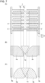
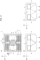
- FIG. 6 schematically illustrates a magnetic-pole-equipped lifting magnet which is an embodiment of the present invention.
- Fig. 6(A) illustrates the magnetic-pole-equipped lifting magnet as viewed from the underside
- Fig. 6(B) is a cross-sectional view taken along line A-A' in Fig. 6(A)
- Fig. 6(C) is a cross-sectional view taken along line B-B' in Fig. 6(A)
- Fig. 6(D) is a cross-sectional view taken along line C-C' in Fig. 6(A) .
- a magnetic-pole-equipped lifting magnet 7 used in an apparatus for conveying steel materials includes the iron core 2 and the yoke 3 disposed opposite each other, with the coil 4 interposed therebetween, the first split magnetic pole 5, and the second split magnetic pole 6.
- the first split magnetic pole 5 and the second split magnetic pole 6 both have a branched structure.
- the configuration of the first and second split magnetic poles 5 and 6 will not be described, as it is the same as that mentioned in the foregoing description of the lifting-magnet attachment magnetic pole unit.
- the "lifting magnet” in Inequality (1) refers to "magnetic-pole-equipped lifting magnet" of the present invention.
- a magnetic field circuit is formed by a magnetic flux applied (input) from the iron core 2 (inner pole) to the first shaft 5a, the first branches 5b, the steel material, the second branches 6b, the second shaft 6a, and the yoke 3 (outer pole) in this order.
- the steel material is thus attracted to the magnetic-pole-equipped lifting magnet.
- the magnetic-pole-equipped lifting magnet of the present invention can achieve the same effects as the lifting-magnet attachment magnetic pole unit described above.
- a lifting-magnet attachment magnetic pole unit and a steel-lifting magnetic-pole-equipped lifting magnet according to a second embodiment are configured basically the same as those of the first embodiment, but differ therefrom in that the first split magnetic pole includes at least one movable magnetic pole and a fixed magnetic pole in a region adjacent to the movable magnetic pole.
- the fixed magnetic pole is disposed on a surface in contact with the steel material.
- the movable magnetic pole is of a movable type.
- the fixed magnetic pole has dimensions satisfying Inequality (2) described below.
- the second embodiment of the present invention can control the number of steel materials to be lifted by one magnetic-pole-equipped lifting magnet, as described above, such that, for example, only one piece of steel material is lifted or only a desired number of (e.g., two or three) pieces of steel material are lifted.
- the present inventors completed the present invention by finding that controlling the penetration depth of magnetic flux in steel materials was effective in controlling the number of steel materials to be lifted. Since techniques other than those related to controlling the number of steel materials to be lifted, are basically the same as those of the first embodiment, redundant description will be omitted.
- the present invention provides a lifting magnet that includes, as in Fig. 11 described below, split magnetic poles structured to divide the magnetic flux output from one coil, and a fixed magnetic pole configured to allow the magnetic flux output from the coil to penetrate to a desired depth.
- the magnetic flux 134 applied from the inner pole 111 into the steel materials is diffused from the bottom of the inner pole 111 toward the bottom of the outer pole 112.
- a region directly below the outer periphery of the inner pole 111 is a portion (neck portion) where the magnetic flux density is highest in the steel materials.
- the cross-sectional area of this portion determines the penetration depth of the magnetic flux 134.
- the penetration depth of the magnetic flux is from the steel material 133a at the top to the steel material 133c at the third level from the top.
- the amount of magnetic flux that can pass through the steel material is expressed as L ⁇ t ⁇ B S , where L (mm) is the total perimeter of a portion where the inner pole 111 is in contact with the lifted steel material 133, t (mm) is the plate thickness of the steel material, and B S (T) is the saturation magnetic flux density in the steel material.
- Patent Literature 4 is a method that controls the mean magnetic flux density (B) in the inner pole by controlling the current value of the coil to satisfy the relational equation A.
- the technique described in Patent Literature 3 is a method that controls the total perimeter (L) of the portion where the inner pole is in contact with the steel material to satisfy the relational equation A.
- a large magnetic-pole lifting magnet such as that typically used in the plate mill of the steel works, has a large maximum magnetic flux penetration depth, as described above.
- Patent Literature 4 when the mean magnetic flux density (B) in the inner pole is controlled by controlling the current value of the coil to adjust the number of steel materials to be lifted, the penetration depth of magnetic flux changes significantly in response to a small change in current. Therefore, if steel materials are of a small (thin) plate thickness, it is difficult to control the number of steel materials to be lifted with high accuracy, because of gaps created by warpage or errors of the magnetic flux sensor.
- the size of the coil may be simply reduced to use a plurality of coils reduced in size.
- using this method to control for example, thin steel materials with a plate thickness of about 5 mm is not practical, because of the resulting increase in the weight of the lifting magnet and in the amount of heat generation in the coil.
- the present inventors examined techniques for adjusting the penetration depth of magnetic flux and obtained the following knowledge.
- the cross-sectional area (S) of the inner pole is proportional to the square of the magnetic pole size
- the total perimeter (L) of the portion where the inner pole is in contact with the steel material is proportional to the magnetic pole size.
- the branched magnetic poles 5b and 6b i.e., split magnetic poles into which the inner and outer poles are partially branched
- the magnetic pole 9 formed into a predetermined size i.e., fixed magnetic pole in contact with the inner pole and disposed in a region in contact with the steel material.
- a magnetic flux is input to the steel material using at least one of the magnetic poles described above.
- the present inventors thus found out that, with this technique, it is possible to control the total perimeter (L) of the portion where the inner pole is in contact with the steel material and to adjust the penetration depth of magnetic flux.
- the mean magnetic flux density (B) in the inner pole can be controlled, where necessary, by current control.
- the present invention it is possible to adjust the maximum penetration depth of magnetic flux to an appropriate level in accordance with the plate thickness of steel materials to be lifted while avoiding an increase in the weight of the lifting magnet and an increase in heat generation in the coil. Also, since the maximum penetration depth of magnetic flux is controlled by magnetic poles, if this control is combined with controlling the penetration depth of magnetic flux using current, the penetration depth of magnetic flux can be controlled with higher accuracy than when only current is used to carry out the control. For example, in the plate mill of the steel works, steel materials with a plate thickness of several mm to several tens of mm are mainly lifted. By varying the design values of magnetic pole sizes, it is theoretically possible to control the number of steel materials to be lifted even if the steel materials are of a smaller plate thickness on the order of 0.1 mm.
- One lifting-magnet attachment magnetic pole unit may have a plurality of magnetic poles (split or fixed magnetic poles) that differ in the total perimeter (L) of the portion where the inner pole is in contact with the steel material. Then, by appropriately switching between magnetic field circuits of these magnetic poles, the maximum penetration depth of magnetic flux can be adjusted. Thus, by using one lifting-magnet attachment magnetic pole unit, the number of steel materials of various plate thicknesses to be lifted can be controlled with high accuracy.
- FIG. 9 schematically illustrates an exemplary lifting-magnet attachment magnetic pole unit used in the second embodiment of the present invention.
- Fig. 10 schematically illustrates another exemplary lifting-magnet attachment magnetic pole unit used in the second embodiment of the present invention.
- Fig. 9(A) and Fig. 10(A) are plan views each illustrating the lifting-magnet attachment magnetic pole unit as viewed from the lifting magnet
- Figs. 9(B) and 9(C) and Figs. 10(B) and 10(C) are plan views each illustrating the lifting-magnet attachment magnetic pole unit as viewed from the steel material.
- the same parts in the drawings are identified by the same reference numerals.
- directions D1 and D2 indicated by two-way arrows are parallel to the steel material surface.
- the lifting-magnet attachment magnetic pole unit used in an apparatus for conveying steel materials includes at least the first split magnetic pole 5 and the second split magnetic pole 6, as in the first embodiment.
- the first split magnetic pole 5 includes the first shaft 5a in contact with an iron core (inner pole) of a lifting magnet, and the plurality of first branches 5b branching off the first shaft 5a.
- the second split magnetic pole 6 includes the second shaft 6a in contact with a yoke (outer pole) of the lifting magnet, and the plurality of second branches 6b branching off the second shaft 6a.
- the first and second branches 5b and 6b are alternately arranged, for example, with spaces or non-magnetic bodies each interposed between adjacent ones of the first and second branches 5b and 6b.
- the first shaft 5a includes at least one movable magnetic pole 8 and a fixed magnetic pole 9.
- the first shaft 5a is divided by the movable magnetic pole 8 into a plurality of regions.
- the fixed magnetic pole 9 is in a region of the first shaft 5a adjacent to the movable magnetic pole 8, and is disposed on a surface in contact with the steel material.
- the movable magnetic pole 8 is of a movable type. In the example illustrated in Fig. 9(C) , the movable magnetic pole 8 is capable of moving in a direction parallel to the first branches 5b (or second branches 6b).
- the movable magnetic pole 8 is moved, for example, using a linear slider.
- the shape (e.g., circular or rectangular shape) of the fixed magnetic pole 9 may be appropriately determined in accordance with the number of steel materials to be lifted.
- Figs. 9(A) to 9(C) illustrate an example where the first shaft 5a is divided by two movable magnetic poles 8 into three regions. Of the three regions, two outer regions each have the first and second branches alternately arranged at predetermined intervals. In the center region (interposed between the two movable magnetic poles 8), the fixed magnetic pole 9 circular in shape is disposed on the surface in contact with the steel material.
- one lifting-magnet attachment magnetic pole unit has therein two magnetic poles (i.e., two magnetic field circuits), the split and fixed magnetic poles. Lifting one piece of steel material involves using the first branch 5b, the second branch 6b, and the fixed magnetic pole 9 as illustrated in Fig. 9(B) , whereas lifting two or more steel materials involves using only the fixed magnetic pole 9 as illustrated in Fig. 9(C) .
- Fig. 9 illustrates an example where adjacent ones of the first and second branches 5b and 6b are provided with a space therebetween.
- the distance X 1 between adjacent ones of the first and second branches 5b and 6b be 30 mm or less. It is more preferable that the distance X 1 be 20 mm or less.
- the lower limit of the distance X 1 is not specified, it is preferable that the distance X 1 be 5 mm or more for preventing the magnetic field circuit from shorting. It is more preferable that the distance X 1 be 10 mm or more.
- the plate thickness T 1 of the first and second split magnetic poles 5 and 6 be 20 mm or less. It is more preferable that the plate thickness T 1 be 15 mm or less. Although the present invention does not specify the lower limit of the plate thickness T 1 , it is preferable that the plate thickness T 1 be 5 mm or more, as in the embodiment described above.
- the plate thickness T 2 of the fixed magnetic pole 9 may be appropriately set in accordance with the maximum total plate thickness T 1 of steel materials to be lifted. For the maximum total plate thickness t 1 of steel materials to be lifted, the plate thickness T 2 of the fixed magnetic pole 9 and the number of branches are set to determine L 1 such that Inequality (2) is satisfied.
- This exemplary lifting-magnet attachment magnetic pole unit has the same structure as that illustrated in Fig. 9 , except that the fixed magnetic pole 9 is quadrangular in shape. Redundant description will therefore be omitted.
- the fixed magnetic pole 9 is configured to be split.
- two rectangular fixed magnetic poles 9 are arranged to extend parallel to the first branches 5b.
- the two fixed magnetic poles 9 are provided with second branches 6c adjacent thereto.
- the second branches 6c may be replaced by spaces or non-magnetic bodies.
- the fixed magnetic pole is configured to be split for the purpose of controlling the penetration depth of magnetic flux in accordance with the maximum total plate thickness of steel materials to be lifted.
- the fixed magnetic pole 9 may be split into two to increase, in limited space, the perimeter of the portion where the intended inner pole is in contact with the steel material. If the perimeter of the portion where the intended inner pole is in contact with the steel material can be secured with one fixed magnetic pole 9 alone, the fixed magnetic pole 9 may be kept undivided.
- the penetration depth of magnetic flux is controlled by switching the path of magnetic flux produced in the coil either to the split and fixed magnetic poles which do not allow the magnetic flux to penetrate deep in the steel material in the plate thickness direction, or to the fixed magnetic pole alone which allows the magnetic flux to penetrate deep in the steel material in the plate thickness direction.
- the switching is made by changing the position of the movable magnetic poles 8.
- Fig. 9(B) and Fig. 10(B) each illustrate the movable magnetic poles 8 that are in contact with the first shaft 5a, that is, the movable magnetic poles 8 that are each located between adjacent regions of the first shaft 5a divided as described above.
- a magnetic field circuit is formed by a magnetic flux applied (input) from the iron core (inner pole) 2 to the fixed magnetic pole 9, the first shaft 5a, the first branches 5b, the steel material, the second branches 6b, the second shaft 6a, and the yoke 3 (outer pole) in this order.
- this allows only one piece of steel material to be lifted using the first split magnetic pole 5, the second split magnetic pole 6, and the fixed magnetic pole 9.
- Fig. 9(C) and Fig. 10(C) each illustrate the movable magnetic poles 8 that are away from the first shaft 5a, that is, the movable magnetic poles 8 that are located outside the gaps between adjacent regions of the first shaft 5a divided as described above.
- the magnetic flux output from the coil is applied only to the fixed magnetic pole 9. This makes the penetration depth of the magnetic flux greater, and allows the magnetic flux to reach the second and subsequent pieces of the steel materials stacked in layers.
- the number of steel materials to be lifted can be controlled by appropriately adjusting the size of the fixed magnetic pole 9 to control the penetration depth for the fixed magnetic pole 9.
- the dimensions of the fixed magnetic pole 9 preferably satisfy Inequality (2) described below.
- the cross-sectional area of the inner pole inside the coil of the lifting magnet is S (mm 2 )
- the mean magnetic flux density in the inner pole inside the coil is B (T)
- the total perimeter of the fixed magnetic pole in a region where the fixed magnetic pole is in contact with a lifted steel material is L 1 (mm)
- the maximum sum of the plate thicknesses of steel materials lifted by the fixed magnetic pole is t 1 (mm)
- the saturation magnetic flux density in the steel material is B S (T).
- the magnetic flux that can pass through the neck portions 113 and 123 in the steel material is expressed as (cross-sectional area of neck portion) ⁇ (saturation magnetic flux density in steel material), that is, L 1 ⁇ t 1 ⁇ B S .
- the magnetic flux applied from the coil is expressed as (cross-sectional area of inner pole) ⁇ (mean magnetic flux density in inner pole), that is, S ⁇ B.
- the penetration depth of magnetic flux can be set to a value appropriate for the maximum total plate thickness (t 1 ) of steel materials to be lifted.
- the penetration depth of magnetic flux can be controlled with higher accuracy.
- the number of plates to be lifted can thus be accurately controlled. Therefore, in particular, even in the case of relatively thin steel materials with a plate thickness of 20 mm or less, it is possible to accurately lift only an intended number of steel materials stacked in layers. In particular, even in the case of steel materials with a plate thickness exceeding 20 mm, it is still possible to achieve the same effects as above.
- the first shaft 5a is connected to the iron core (inner pole) of a typical electromagnetic lifting magnet and the second shaft 6a is connected to the yoke (outer pole) of the lifting magnet to form the first and second split magnetic poles 5 and 6 having a branched structure and the fixed magnetic pole 9 on the typical lifting magnet.
- the lifting-magnet attachment magnetic pole unit according to the second embodiment of the present invention may be of an attachment type that can be attached later to the inner pole and the outer pole of the typical lifting magnet described above.
- the magnetic poles (inner and outer poles) of the lifting magnet themselves may be divided into branched magnetic poles (first and second branches 5b and 6b), and the first shaft 5a may be divided by movable magnetic poles to provide a fixed magnetic pole in a predetermined region. In either case, the same effects as the present invention can be achieved.
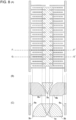
- FIG. 11 schematically illustrates an exemplary magnetic-pole-equipped lifting magnet according to the second embodiment of the present invention.
- Fig. 11(A) is a plan view of the magnetic-pole-equipped lifting magnet as viewed from the underside
- Fig. 11(B) is a cross-sectional view taken along line H-H' in Fig. 11(A)
- Fig. 11(C) is a cross-sectional view taken along line I-I' in Fig. 11(A) .
- the magnetic-pole-equipped lifting magnet 7 used in an apparatus for conveying steel materials includes the iron core 2 (inner pole) and the yoke 3 (outer pole) disposed opposite each other, with the coil 4 interposed therebetween, the first split magnetic pole 5, and the second split magnetic pole 6.
- the first split magnetic pole 5 and the second split magnetic pole 6 both have a branched structure.
- the first shaft 5a of the first split magnetic pole 5 is divided by at least one movable magnetic pole 8, and the first split magnetic pole 5 has the fixed magnetic pole 9 in a region interposed between movable magnetic poles 8.
- Fig. 11(A) illustrates an example where the first shaft 5a is divided by two movable magnetic poles 8 into three sections.
- the “lifting magnet” in Inequality (2) refers to “magnetic-pole-equipped lifting magnet” of the present invention.
- a magnetic field circuit is formed by a magnetic flux applied (input) from the iron core 2 (inner pole) to the fixed magnetic pole 9, the first shaft 5a, the first branches 5b, the steel material, the second branches 6b, the second shaft 6a, and the yoke 3 (outer pole) in this order.
- the movable magnetic poles 8 are located in contact with the first shaft 5a, a magnetic flux is output and branched from the inner pole toward the outer pole, through the first branches 5b, the second branches 6b, and the fixed magnetic pole 9.
- a magnetic field circuit can be controlled to be formed either on the side of the first branches 5b and the second branches 6b and in the fixed magnetic pole 9, or only in the fixed magnetic pole 9.
- a magnetic flux output from one coil is applied to the steel materials through the split magnetic poles or the fixed magnetic pole, so that the maximum penetration depth of magnetic flux in the steel materials can be controlled. That is, in the present invention, by changing the magnetic field circuit as described above, the maximum penetration depth of magnetic flux can be changed to a desired value.
- the number of pieces of steel materials to be lifted can be easily controlled with high accuracy.
- the one magnetic pole unit can accommodate lifting of steel materials of various plate thicknesses.
- the present invention is applicable to methods for conveying steel materials in such places as steel works.
- Either of the lifting-magnet attachment magnetic pole unit and the steel-lifting magnetic-pole-equipped lifting magnet, according to the first and second embodiments described above, can be used here.
- the lifting-magnet attachment magnetic pole unit is attached to a typical lifting magnet and steel materials are lifted and conveyed with the magnetic force.
- a magnetic-pole-equipped lifting magnet is used, steel materials are lifted and conveyed with the magnetic force of the lifting magnet.
- the steel material (e.g., steel plate) conveying apparatus may include, at an attracting portion for lifting of steel materials, a lifting magnet with the lifting-magnet attachment magnetic pole unit illustrated in Fig. 4 attached thereto or the magnetic-pole-equipped lifting magnet illustrated in Fig. 6 .
- the conveying apparatus may include, at an attracting portion for lifting of steel materials, a lifting magnet with the lifting-magnet attachment magnetic pole unit illustrated in Figs. 9 and 10 attached thereto or the magnetic-pole-equipped lifting magnet illustrated in Fig. 11 .
- the present invention is a steel plate manufacturing method in which, by using the steel material conveying method which involves using the lifting-magnet attachment magnetic pole unit or the magnetic-pole-equipped lifting magnet according to the first and second embodiments, each or only some (e.g., two or three) intended pieces of steel plate stored in a steel plate storage place (storage area) after rolling are lifted and conveyed with magnetic force, and subjected to a finishing step.
- steel plates can be manufactured by heating a steel having a predetermined component composition, applying hot rolling to the steel, cooling the steel, and shearing the steel into a desired size.
- the component composition of the steel applicable to the steel plate manufacturing method of the present invention is not particularly limited, and steel having a known component composition may be used.
- heating and cooling temperature conditions and the rolling reduction ratio are not particularly limited, and known conditions can be employed.
- Fig. 7 schematically illustrates a configuration of a lifting-magnet attachment magnetic pole unit according to the first embodiment of the present invention, used in Example 1.
- Fig. 7(A) is a plan view of the lifting-magnet attachment magnetic pole unit, as viewed from the underside
- Fig. 7(B) is a cross-sectional view taken along line D-D' in Fig. 7(A)
- Fig. 7(C) is a cross-sectional view taken along line E-E' in Fig. 7(A) .
- Example 1 as an example of the present invention, a steel plate lifting test was performed using a magnetic-pole-equipped lifting magnet, such as that illustrated in Fig. 6 , obtained by attaching the lifting-magnet attachment magnetic pole unit (made of SS400) of the present invention illustrated in Fig. 7 to a lifting magnet (not shown) including an inner pole 150 mm in diameter and an outer pole 60 mm in thickness and 500 mm ⁇ 500 mm in size.
- the magnetic pole unit is 10 mm thick, and the inner pole and the outer pole have a 20 mm gap therebetween.
- the dimensions of the first and second split magnetic poles are not particularly limited.
- As steel plates to be lifted SS400 plates 5 mm in plate thickness, 3 m long ⁇ 1.5 m wide, and weighing about 180 kg were used. Of ten steel plates stacked in layers, the uppermost piece (first plate) was attracted by the lifting magnet and attraction weight (attracting force) exerted on each steel plate was measured. The result of the measurement is shown in Table 1.
- Table 1 shows that a large attracting force of 770 kgf was exerted on the first piece of plate at the top, whereas an attracting force exerted on the second piece of plate underneath was 110 kgf, an attracting force exerted on the third piece of plate underneath was 4 kgf, and an attracting force exerted on the fourth and subsequent pieces of plate further underneath was less than or equal to a measurement limit (0 kgf).
- the steel plates each weigh about 180 kg and this shows that the second and subsequent steel plates are not attracted.
- the first split magnetic pole 5 and the second split magnetic pole 6 of the magnetic pole unit described above were formed to have predetermined dimensions.
- a steel plate lifting test was performed in the same manner as above.
- Table 1 shows that a large attracting force of 1800 kgf was exerted on the first piece of plate at the top, whereas an attracting force exerted on the second piece of plate underneath was 1 kgf, and an attracting force exerted on the third and subsequent pieces of plate further underneath was less than or equal to the measurement limit.
- the steel plates each weigh about 180 kg and this shows that the second and subsequent pieces of steel plate are not attracted.
- Example 1 shows that in the examples of the present invention described above, where substantially the entire magnetic flux produced by the coil is concentrated on the first plate, only the uppermost piece of ten pieces of steel plate stacked in layers can be lifted. A result similar to this can be obtained even when the lifting-magnet attachment magnetic pole unit is replaced by a magnetic-pole-equipped lifting magnet of the present invention configured with the same dimensions.
- Fig. 8 schematically illustrates a configuration of a lifting-magnet attachment magnetic pole unit according to the first embodiment, used in Example 2.
- Fig. 8(A) is a plan view of the lifting-magnet attachment magnetic pole unit, as viewed from the underside
- Fig. 8(B) is a cross-sectional view taken along line F-F' in Fig. 8(A)
- Fig. 8(C) is a cross-sectional view taken along line G-G' in Fig. 8 (A) .
- Example 2 as an example of the present invention, a steel plate lifting test was performed using a magnetic-pole-equipped lifting magnet, such as that illustrated in Fig. 6 , obtained by attaching the lifting-magnet attachment magnetic pole unit (made of SS400) of the present invention illustrated in Fig. 8 to a lifting magnet (not shown) including an inner pole 1000 mm ⁇ 100 mm in size and an outer pole 60 mm in thickness and 1500 mm ⁇ 500 mm in size.
- the magnetic pole unit is 20 mm thick, and the inner pole and the outer pole have a 30 mm gap therebetween.
- the dimensions of the first and second split magnetic poles are not particularly limited.
- Table 2 shows that a large attracting force of 3800 kgf was exerted on the first piece of plate at the top, whereas an attracting force exerted on the second piece of plate underneath was 540 kgf, an attracting force exerted on the third plate underneath was 5 kgf, and an attracting force exerted on the fourth and subsequent pieces of plate further underneath was less than or equal to a measurement limit (0 kgf).
- the steel plates each weigh about 720 kg and this shows that the second and subsequent pieces of steel plate underneath are not attracted.
- the first and second split magnetic poles 5 and 6 of the magnetic pole unit described above were formed to have predetermined dimensions.
- a steel plate lifting test was performed in the same manner as above.
- Table 2 shows that a large attracting force of 8500 kgf was exerted on the first piece of plate at the top, whereas an attracting force exerted on the second piece of plate underneath was 5 kgf and an attracting force exerted on the third and subsequent plates further underneath was less than or equal to the measurement limit.
- the steel plates each weigh about 720 kg and this shows that the second and subsequent pieces of steel plate are not attracted.
- Example 2 shows that in the examples of the present invention described above, where substantially the entire magnetic flux produced by the coil is concentrated on the first plate, only the uppermost piece of ten steel plates stacked in layers can be lifted. A result similar to this can be obtained even when the lifting-magnet attachment magnetic pole unit is replaced by a magnetic-pole-equipped lifting magnet of the present invention configured with the same dimensions.
- Example 3 the lifting-magnet attachment magnetic pole unit according to the second embodiment of the present invention, illustrated in Fig. 9 , was used.
- Example 3 as an example of the present invention, a steel plate lifting test was performed using the magnetic-pole-equipped lifting magnet, illustrated in Fig. 11(A) , obtained by attaching the lifting-magnet attachment magnetic pole unit (made of SS400) illustrated in Fig. 9 to a lifting magnet (not shown) including an inner pole 100 mm in diameter and an outer pole 25 mm in thickness and 350 mm ⁇ 350 mm in size.
- the first and second split magnetic poles 5 and 6 are 10 mm thick, and the first and second split magnetic poles 5 and 6 have a 10 mm gap therebetween.
- the first and second split magnetic poles 5 and 6 are designed to lift one piece of plate at the top.
- the fixed magnetic pole 9 is circular in shape and is 100 mm in diameter.
- the fixed magnetic pole 9 is designed to lift three pieces of steel material at the top.
- the magnetic field circuit was switched by moving the movable magnetic poles 8 with a linear slider.
- the fixed magnetic pole 9 is configured to have dimensions that satisfy Inequality (2).
- the left column of Table 3 shows the measurement result of lifting with the first and second split magnetic poles 5 and 6 and the fixed magnetic pole 9, whereas the right column of Table 3 shows the measurement result of lifting with only the fixed magnetic pole 9.
- Table 3 shows that in the case of lifting with the first and second split magnetic poles 5 and 6 and the fixed magnetic pole 9, a large attracting force of 3800 kgf was exerted on the first plate at the top, whereas an attracting force exerted on the second piece of plate underneath was 1 kgf and an attracting force exerted on the third and subsequent pieces of plate further underneath was less than or equal to the measurement limit (0 kgf).
- an attracting force exerted on the first piece of plate at the top was 1370 kgf
- an attracting force exerted on the second piece of plate underneath was 600 kgf
- an attracting force exerted on the third piece of plate underneath was 490 kgf
- an attracting force exerted on the fourth piece of plate underneath was 2 kgf
- an attracting force exerted on the fifth piece of plate underneath was less than or equal to the measurement limit (0 kgf).
- Example 3 shows that by switching the magnetic field circuit with the movable magnetic poles 8, the number of steel plates that can be lifted with only one magnetic-pole-equipped lifting magnet can be controlled between one and three. Although no measurement result is shown, if, in the case of lifting with only the fixed magnetic pole 9, the control described above is combined with the control of current applied to the coil, lifting of two plates is also possible.
- Example 4 the lifting-magnet attachment magnetic pole unit according to the second embodiment of the present invention, illustrated in Fig. 10 , was used.
- Example 4 as an example of the present invention, a steel plate lifting test was performed using the magnetic-pole-equipped lifting magnet, illustrated in Fig. 11(A) , obtained by attaching the lifting-magnet attachment magnetic pole unit (made of SS400) illustrated in Fig. 10 to a lifting magnet (not shown) including an inner pole 100 mm in diameter and an outer pole 25 mm in thickness and 350 mm ⁇ 350 mm in size.
- the first and second split magnetic poles 5 and 6 are 10 mm thick, and the first and second split magnetic poles 5 and 6 have a 10 mm gap therebetween.
- the first and second split magnetic poles 5 and 6 are designed to lift one piece of plate at the top.
- the fixed magnetic pole 9 is split into two separate rectangles, which are 20 mm thick. Each separate portion of the fixed magnetic pole 9 and the second branch 6c adjacent thereto have a 10 mm gap therebetween.
- the fixed magnetic pole 9 is designed to lift two pieces of steel material at the top.
- the magnetic field circuit was switched by moving the movable magnetic poles 8 with a linear slider.
- the fixed magnetic pole 9 is configured to have dimensions that satisfy Inequality (2).
- the estimated mean magnetic flux density in the inner pole inside the coil was 1 T, and the saturation magnetic flux density of SS400 was about 2 T. Therefore, when the cross-sectional area S (mm 2 ) of the inner pole inside the coil is 7850 mm 2 , the mean magnetic flux density B (T) in the inner pole inside the coil is 1.0, and the total perimeter of a portion where the fixed magnetic pole 9 is in contact with a lifted steel material is L 1 (mm), then the total perimeter of a portion where the first split magnetic pole 5 is in contact with the steel material is 3180 mm, the total perimeter of the portion where the fixed magnetic pole 9 is in contact with the steel material is 540 mm, and the maximum sum t 1 (mm) of the plate thicknesses of steel plates lifted by the fixed magnetic pole is 10 mm.
- the left column of Table 4 shows the measurement result of lifting with the first and second split magnetic poles 5 and 6 and the fixed magnetic pole 9, whereas the right column of Table 4 shows the measurement result of lifting with only the fixed magnetic pole 9.
- Table 4 shows that in the case of lifting with the first and second split magnetic poles 5 and 6 and the fixed magnetic pole 9, a large attracting force of 3800 kgf was exerted on the first plate at the top, whereas an attracting force exerted on the second plate underneath was 1 kgf and an attracting force exerted on the third and subsequent plates underneath was less than or equal to the measurement limit (0 kgf).
- an attracting force exerted on the first plate at the top was 1530 kgf
- an attracting force exerted on the second plate underneath was 700 kgf
- an attracting force exerted on the third plate underneath was 3 kgf
- an attracting force exerted on the fourth and subsequent plates underneath was less than or equal to the measurement limit (0 kgf).
- Example 4 shows that by switching the magnetic field circuit with the movable magnetic poles 8, the number of steel plates that can be lifted with only one magnetic-pole-equipped lifting magnet can be controlled between one and two.
Landscapes
- Physics & Mathematics (AREA)
- Electromagnetism (AREA)
- Engineering & Computer Science (AREA)
- Mechanical Engineering (AREA)
- Power Engineering (AREA)
- Chemical & Material Sciences (AREA)
- Composite Materials (AREA)
- Load-Engaging Elements For Cranes (AREA)
Claims (11)
- Hubmagnetbefestigungsmagnetpoleinheit für einen Hubmagnet zum Heben und Befördern von Stahlmaterial mit Magnetkraft, wobei die Hubmagnetbefestigungsmagnetpoleinheit aufweist:einen ersten geteilten Magnetpol (5), aufweisendeinen ersten Schaft (5a), der mit einem Eisenkern des Hubmagnets in Kontakt ist; undeinen zweiten geteilten Magnetpol (6), aufweisendeinen zweiten Schaft (6a) in Kontakt mit einem Joch des Hubmagnets,dadurch gekennzeichnet, dass der erste geteilte Magnetpol (5) eine Mehrzahl von ersten Zweigen (5b) aufweist, die dazu ausgestaltet ist, den ersten Schaft (5a) zu verzweigen, und der zweite Magnetpol (6) eine Mehrzahl von zweiten Zweigen (6b) aufweist, die dazu ausgestaltet ist, den zweiten Schaft (6a) zu verzweigen,wobei die ersten und zweiten Zweige (5b, 6b) wechselweise angeordnet sind.
- Hubmagnetbefestigungsmagnetpoleinheit nach Anspruch 1, wobei der erste geteilte Magnetpol (5) Abmessungen aufweist, die Ungleichung (1) erfüllen:
 S eine Querschnittsfläche (mm2) eines inneren Pols des Hubmagnets ist;B eine mittlere magnetische Flussdichte (T) innerhalb des inneren Pols des Hubmagnets ist;L ein Gesamtumfang (mm) des ersten geteilten Magnetpols (5) in einem Bereich ist, in dem der erste geteilte Magnetpol (5) in Kontakt mit einem gehobenen Stahlmaterial ist;t eine Plattendicke (mm) des gehobenen Stahlmaterials ist; undBS eine magnetische Sättigungsflussdichte (T) in dem gehobenen Stahlmaterial ist.
 - Hubmagnetbefestigungsmagnetpoleinheit nach Anspruch 1 oder 2, wobei der erste geteilte Magnetpol (5) zumindest einen bewegbaren Magnetpol und einen feststehenden Magnetpol (9) in einem zu dem bewegbaren Magnetpol (8) benachbarten Bereich aufweist, wobei der feststehende Magnetpol an einer Oberfläche angeordnet ist, die mit dem Stahlmaterial in Kontakt ist.
- Hubmagnetbefestigungsmagnetpoleinheit nach Anspruch 3, wobei der bewegbare Magnetpol (8) von einem bewegbaren Typ ist.
- Hubmagnetbefestigungsmagnetpoleinheit nach Anspruch 3 oder 4, wobei der feststehende Magnetpol (9) Abmessungen aufweist, die Ungleichung (2) erfüllen:
 S eine Querschnittsfläche (mm2) eines inneren Pols des Hubmagnets ist;B eine mittlere magnetische Flussdichte (T) innerhalb des inneren Pols des Hubmagnets ist;L1 ein Gesamtumfang (mm) des feststehenden Magnetpols (9) in einem Bereich ist, in dem der feststehende Magnetpol mit einem gehobenen Stahlmaterial in Kontakt ist;t1 eine maximale Summe (mm) der Plattendicken der Stahlmaterialien ist, die durch den feststehenden Magnetpol (9) gehoben werden; undBS eine magnetische Sättigungsflussdichte (T) in den gehobenen Stahlmaterialien ist.
 - Hubmagnetbefestigungsmagnetpoleinheit nach einem der Ansprüche 1 bis 5, wobei ein Abstand zwischen dem ersten und zweiten geteilten Magnetpol (5, 6), die wechselweise angeordnet sind, 30 mm oder weniger ist.
- Hubmagnetbefestigungsmagnetpoleinheit nach einem der Ansprüche 1 bis 6, wobei der erste und zweite Magnetpol (5, 6) jeweils eine Plattendicke von 20 mm oder weniger aufweisen.
- Hubmagnet zum Heben und Befördern eines Stahlmaterials mit Magnetkraft, wobei der Hubmagnet als der Magnetpol die Hubmagnetbefestigungsmagnetpoleinheit nach einem der Ansprüche 1 bis 7 aufweist.
- Stahlmaterialbeförderungsverfahren unter Einsatz der Hubmagnetbefestigungsmagnetpoleinheit nach einem der Ansprüche 1 bis 7, wobei das Stahlmaterialbeförderungsverfahren ein Befestigen der Hubmagnetbefestigungsmagnetpoleinheit an einem Hubmagnet und ein Heben und Befördern eines Stahlmagnets mit Magnetkraft umfasst.
- Stahlmaterialbeförderungsverfahren unter Einsatz des mit dem stahlhebenden Magnetpol ausgestatteten Hubmagnets nach Anspruch 8, wobei das Stahlmaterialbeförderungsverfahren ein Heben und Befördern eines Stahlmaterials mit Magnetkraft umfasst.
- Stahlplattenherstellungsverfahren umfassend ein Befördern einer Stahlplatte unter Einsatz des Stahlmaterialbeförderungsverfahrens nach einem der Ansprüche 9 oder 10 nach einem Rollen und ein Ausführen eines Endbearbeitungsschritts.
Applications Claiming Priority (2)
| Application Number | Priority Date | Filing Date | Title |
|---|---|---|---|
| JP2017228619 | 2017-11-29 | ||
| PCT/JP2018/044025 WO2019107504A1 (ja) | 2017-11-29 | 2018-11-29 | リフティングマグネット用取り付け磁極、鋼材吊上げ用磁極付リフティングマグネット、鋼材の搬送方法、並びに鋼板の製造方法 |
Publications (3)
| Publication Number | Publication Date |
|---|---|
| EP3718946A1 EP3718946A1 (de) | 2020-10-07 |
| EP3718946A4 EP3718946A4 (de) | 2021-01-13 |
| EP3718946B1 true EP3718946B1 (de) | 2024-09-11 |
Family
ID=66665700
Family Applications (1)
| Application Number | Title | Priority Date | Filing Date |
|---|---|---|---|
| EP18883651.4A Active EP3718946B1 (de) | 2017-11-29 | 2018-11-29 | Befestigungsmagnetpol für hubmagnet, hubmagnet mit magnetpol zum heben von stahlmaterial, verfahren zum fördern von stahlmaterial und verfahren zur herstellung von stahlblech |
Country Status (6)
| Country | Link |
|---|---|
| US (1) | US11875940B2 (de) |
| EP (1) | EP3718946B1 (de) |
| JP (1) | JP6787484B2 (de) |
| KR (1) | KR102435215B1 (de) |
| CN (1) | CN111417591B (de) |
| WO (1) | WO2019107504A1 (de) |
Families Citing this family (4)
| Publication number | Priority date | Publication date | Assignee | Title |
|---|---|---|---|---|
| WO2019107504A1 (ja) * | 2017-11-29 | 2019-06-06 | Jfeスチール株式会社 | リフティングマグネット用取り付け磁極、鋼材吊上げ用磁極付リフティングマグネット、鋼材の搬送方法、並びに鋼板の製造方法 |
| EP4122866B1 (de) * | 2020-05-26 | 2025-07-02 | JFE Steel Corporation | Hebemagnet, stahlblechhebevorrichtung und stahlblechförderverfahren |
| CN112678664B (zh) * | 2020-12-29 | 2025-09-02 | 大连星航起重吊具有限公司 | 一种精确吸多张钢板的起重电磁铁和控制方法 |
| US12441589B2 (en) | 2021-02-26 | 2025-10-14 | Jfe Steel Corporation | Steel plate lifting method with use of lifting magnet, lifting magnet, and method for manufacturing steel plate by using lifting magnet |
Family Cites Families (30)
| Publication number | Priority date | Publication date | Assignee | Title |
|---|---|---|---|---|
| DE2210193A1 (de) * | 1972-03-03 | 1973-09-06 | Heinrich Dipl Ing List | Last- und hebe- magnet mit permanentmagnetischer fluss- und kraft-erzeugung |
| JPS5717832B2 (de) * | 1974-06-21 | 1982-04-13 | ||
| JPS5436451Y2 (de) * | 1975-06-02 | 1979-11-02 | ||
| JPS5328265A (en) * | 1976-08-30 | 1978-03-16 | Nippon Steel Corp | Lifting magnet |
| JPS5926597B2 (ja) * | 1981-04-23 | 1984-06-28 | 神鋼電機株式会社 | 溶融アルミニウム内鉄片の吊上用電磁石 |
| JPS5918555U (ja) * | 1982-07-22 | 1984-02-04 | 三菱電機株式会社 | 電動機の支持装置 |
| JPS5928555U (ja) * | 1982-08-13 | 1984-02-22 | 神鋼電機株式会社 | リフテイングマグネツト |
| JP2602649B2 (ja) * | 1987-04-02 | 1997-04-23 | 鐘通工業 株式会社 | 永久磁石式電磁チヤツク |
| JPH053508Y2 (de) * | 1987-06-26 | 1993-01-27 | ||
| JPH06104548B2 (ja) | 1989-05-11 | 1994-12-21 | 新日本製鐵株式会社 | リフティングマグネットクレーン装置 |
| CN2130798Y (zh) * | 1992-06-20 | 1993-04-28 | 大连理工大学 | 永磁起重吸盘 |
| JPH07277664A (ja) | 1994-04-04 | 1995-10-24 | Hitachi Metals Ltd | 吊上装置 |
| JP3131679B2 (ja) * | 1995-09-05 | 2001-02-05 | 日立機材株式会社 | 吊上装置 |
| EP0801304B1 (de) * | 1995-10-31 | 2001-10-10 | Nkk Corporation | Vorrichtung zur magnetischen fehlerdetektion |
| KR200150655Y1 (ko) * | 1995-12-27 | 1999-07-01 | 이구택 | 전기자석크레인 후판매수 검출장치 |
| JPH10194656A (ja) | 1996-12-27 | 1998-07-28 | Shinko Electric Co Ltd | 旋回機構を備えた励磁区分選択が可能な吊り上げ電磁石装置 |
| JP2000226179A (ja) | 1999-02-04 | 2000-08-15 | Mitsubishi Plastics Ind Ltd | 吊上げ装置 |
| KR100406432B1 (ko) * | 2001-12-22 | 2003-11-19 | 재단법인 포항산업과학연구원 | 영구자석을 이용한 코일 권상기 |
| JP2007217119A (ja) * | 2006-02-16 | 2007-08-30 | Sumitomo Heavy Ind Ltd | リフティングマグネット |
| CN200974738Y (zh) * | 2006-12-01 | 2007-11-14 | 杨祖成 | 废钢起重电磁铁 |
| CN201024036Y (zh) * | 2007-04-09 | 2008-02-20 | 杨祖成 | 钢板材起重电磁铁 |
| CN201056454Y (zh) * | 2007-04-28 | 2008-05-07 | 杨祖成 | 钢板起重电磁铁 |
| CN201056457Y (zh) * | 2007-05-17 | 2008-05-07 | 杨祖成 | 钢轨起重电磁铁 |
| KR20110132686A (ko) * | 2010-06-03 | 2011-12-09 | 김상현 | 권상기용 전자석 |
| KR101125280B1 (ko) * | 2010-09-20 | 2012-03-21 | 최태광 | 영구자석과 전자석을 결합한 자성체 홀딩장치 |
| JP5773667B2 (ja) * | 2011-01-31 | 2015-09-02 | 東芝エレベータ株式会社 | 磁石ユニットおよびエレベータの磁気ガイド装置 |
| KR20120073164A (ko) * | 2012-05-14 | 2012-07-04 | 최규철 | 후판 이송시스템 |
| JP2015027903A (ja) * | 2013-07-30 | 2015-02-12 | シンフォニアテクノロジー株式会社 | リフティングマグネット |
| CN109952628B (zh) * | 2016-11-04 | 2020-08-25 | 株式会社电装 | 电磁继电器 |
| WO2019107504A1 (ja) * | 2017-11-29 | 2019-06-06 | Jfeスチール株式会社 | リフティングマグネット用取り付け磁極、鋼材吊上げ用磁極付リフティングマグネット、鋼材の搬送方法、並びに鋼板の製造方法 |
-
2018
- 2018-11-29 WO PCT/JP2018/044025 patent/WO2019107504A1/ja not_active Ceased
- 2018-11-29 JP JP2019510467A patent/JP6787484B2/ja active Active
- 2018-11-29 US US16/767,200 patent/US11875940B2/en active Active
- 2018-11-29 EP EP18883651.4A patent/EP3718946B1/de active Active
- 2018-11-29 CN CN201880076571.XA patent/CN111417591B/zh active Active
- 2018-11-29 KR KR1020207015568A patent/KR102435215B1/ko active Active
Also Published As
| Publication number | Publication date |
|---|---|
| KR20200074211A (ko) | 2020-06-24 |
| EP3718946A4 (de) | 2021-01-13 |
| JPWO2019107504A1 (ja) | 2019-12-12 |
| CN111417591A (zh) | 2020-07-14 |
| KR102435215B1 (ko) | 2022-08-22 |
| US11875940B2 (en) | 2024-01-16 |
| WO2019107504A1 (ja) | 2019-06-06 |
| EP3718946A1 (de) | 2020-10-07 |
| US20200385240A1 (en) | 2020-12-10 |
| JP6787484B2 (ja) | 2020-11-18 |
| CN111417591B (zh) | 2022-05-24 |
Similar Documents
| Publication | Publication Date | Title |
|---|---|---|
| EP3718946B1 (de) | Befestigungsmagnetpol für hubmagnet, hubmagnet mit magnetpol zum heben von stahlmaterial, verfahren zum fördern von stahlmaterial und verfahren zur herstellung von stahlblech | |
| DE69215278T2 (de) | Supraleitender Verbundkörper und Schwebesystem | |
| US7506566B2 (en) | Bulk stamped amorphous metal magnetic component | |
| DE102010028769A1 (de) | System zum Transportieren von Behältern zwischen unterschiedlichen Stationen und Behälterträger | |
| CZ20014215A3 (cs) | Způsob zlepąení magnetických charakteristik křemíkových ocelových plechů s orientovanými zrny pro elektrotechnické účely působením laseru | |
| EP3901971A1 (de) | Kornorientiertes elektrisches stahlblech und herstellungsverfahren dafür | |
| US20120299686A1 (en) | Static apparatus | |
| Leuning et al. | Analysis of a novel laser welding strategy for electrical steel laminations | |
| US20120312432A1 (en) | Metallic material as a solid solution having a body-centered cubic (bcc) structure, an orientation of crystal axis <001> of which is controlled, and method of manufacturing the same | |
| KR102716688B1 (ko) | 누설 자기 검사 장치 및 결함 검사 방법 | |
| KR20120073164A (ko) | 후판 이송시스템 | |
| EP4257532A1 (de) | Stahlblechhebeverfahren mit hebemagnet, hebemagnet und stahlblechherstellungsverfahren mit hebemagnet | |
| EP4122866B1 (de) | Hebemagnet, stahlblechhebevorrichtung und stahlblechförderverfahren | |
| DE102008017984A1 (de) | Magnetlager sowie Verfahren zur Herstellung eines dafür geeigneten Lagerrings | |
| JP4597715B2 (ja) | 磁気加熱装置 | |
| RU2479480C1 (ru) | Прямоугольный грузоподъемный электромагнит | |
| JP4473442B2 (ja) | 方向性電磁鋼板コイルの切断装置 | |
| JP5850713B2 (ja) | マグネトロンスパッタリング装置及びマグネトロンスパッタリング方法 | |
| KR101821578B1 (ko) | 광폭 강판용 전자석 리프터 | |
| CN224005774U (zh) | 一种铁芯硅钢片接料平台 | |
| Fujisaki | Application of electromagnetic force to runout table | |
| JPH09275022A (ja) | 磁気特性の優れた低騒音鉄心 | |
| JP2015200522A (ja) | 保磁力分布磁石の保磁力性能判定装置 | |
| Ding et al. | Design of lifting permanent magnet based on neural network | |
| US20160133367A1 (en) | Methods and systems for fabricating amorphous ribbon assembly components for stacked transformer cores |
Legal Events
| Date | Code | Title | Description |
|---|---|---|---|
| STAA | Information on the status of an ep patent application or granted ep patent |
Free format text: STATUS: THE INTERNATIONAL PUBLICATION HAS BEEN MADE |
|
| PUAI | Public reference made under article 153(3) epc to a published international application that has entered the european phase |
Free format text: ORIGINAL CODE: 0009012 |
|
| STAA | Information on the status of an ep patent application or granted ep patent |
Free format text: STATUS: REQUEST FOR EXAMINATION WAS MADE |
|
| 17P | Request for examination filed |
Effective date: 20200528 |
|
| AK | Designated contracting states |
Kind code of ref document: A1 Designated state(s): AL AT BE BG CH CY CZ DE DK EE ES FI FR GB GR HR HU IE IS IT LI LT LU LV MC MK MT NL NO PL PT RO RS SE SI SK SM TR |
|
| AX | Request for extension of the european patent |
Extension state: BA ME |
|
| A4 | Supplementary search report drawn up and despatched |
Effective date: 20201211 |
|
| RIC1 | Information provided on ipc code assigned before grant |
Ipc: B66C 1/06 20060101AFI20201207BHEP |
|
| DAV | Request for validation of the european patent (deleted) | ||
| DAX | Request for extension of the european patent (deleted) | ||
| STAA | Information on the status of an ep patent application or granted ep patent |
Free format text: STATUS: EXAMINATION IS IN PROGRESS |
|
| 17Q | First examination report despatched |
Effective date: 20220831 |
|
| GRAP | Despatch of communication of intention to grant a patent |
Free format text: ORIGINAL CODE: EPIDOSNIGR1 |
|
| STAA | Information on the status of an ep patent application or granted ep patent |
Free format text: STATUS: GRANT OF PATENT IS INTENDED |
|
| INTG | Intention to grant announced |
Effective date: 20231130 |
|
| GRAJ | Information related to disapproval of communication of intention to grant by the applicant or resumption of examination proceedings by the epo deleted |
Free format text: ORIGINAL CODE: EPIDOSDIGR1 |
|
| STAA | Information on the status of an ep patent application or granted ep patent |
Free format text: STATUS: EXAMINATION IS IN PROGRESS |
|
| INTC | Intention to grant announced (deleted) | ||
| GRAP | Despatch of communication of intention to grant a patent |
Free format text: ORIGINAL CODE: EPIDOSNIGR1 |
|
| STAA | Information on the status of an ep patent application or granted ep patent |
Free format text: STATUS: GRANT OF PATENT IS INTENDED |
|
| INTG | Intention to grant announced |
Effective date: 20240411 |
|
| RIN1 | Information on inventor provided before grant (corrected) |
Inventor name: YOTSUJI, JUNICHI Inventor name: KOBAYASHI, MASAKI Inventor name: TAKAKI, YUKI |
|
| GRAS | Grant fee paid |
Free format text: ORIGINAL CODE: EPIDOSNIGR3 |
|
| GRAA | (expected) grant |
Free format text: ORIGINAL CODE: 0009210 |
|
| STAA | Information on the status of an ep patent application or granted ep patent |
Free format text: STATUS: THE PATENT HAS BEEN GRANTED |
|
| AK | Designated contracting states |
Kind code of ref document: B1 Designated state(s): AL AT BE BG CH CY CZ DE DK EE ES FI FR GB GR HR HU IE IS IT LI LT LU LV MC MK MT NL NO PL PT RO RS SE SI SK SM TR |
|
| REG | Reference to a national code |
Ref country code: GB Ref legal event code: FG4D |
|
| REG | Reference to a national code |
Ref country code: CH Ref legal event code: EP |
|
| REG | Reference to a national code |
Ref country code: DE Ref legal event code: R096 Ref document number: 602018074380 Country of ref document: DE |
|
| REG | Reference to a national code |
Ref country code: IE Ref legal event code: FG4D |
|
| REG | Reference to a national code |
Ref country code: LT Ref legal event code: MG9D |
|
| PG25 | Lapsed in a contracting state [announced via postgrant information from national office to epo] |
Ref country code: NO Free format text: LAPSE BECAUSE OF FAILURE TO SUBMIT A TRANSLATION OF THE DESCRIPTION OR TO PAY THE FEE WITHIN THE PRESCRIBED TIME-LIMIT Effective date: 20241211 |
|
| REG | Reference to a national code |
Ref country code: NL Ref legal event code: MP Effective date: 20240911 |
|
| PG25 | Lapsed in a contracting state [announced via postgrant information from national office to epo] |
Ref country code: FI Free format text: LAPSE BECAUSE OF FAILURE TO SUBMIT A TRANSLATION OF THE DESCRIPTION OR TO PAY THE FEE WITHIN THE PRESCRIBED TIME-LIMIT Effective date: 20240911 Ref country code: GR Free format text: LAPSE BECAUSE OF FAILURE TO SUBMIT A TRANSLATION OF THE DESCRIPTION OR TO PAY THE FEE WITHIN THE PRESCRIBED TIME-LIMIT Effective date: 20241212 |
|
| PG25 | Lapsed in a contracting state [announced via postgrant information from national office to epo] |
Ref country code: BG Free format text: LAPSE BECAUSE OF FAILURE TO SUBMIT A TRANSLATION OF THE DESCRIPTION OR TO PAY THE FEE WITHIN THE PRESCRIBED TIME-LIMIT Effective date: 20240911 |
|
| PG25 | Lapsed in a contracting state [announced via postgrant information from national office to epo] |
Ref country code: LV Free format text: LAPSE BECAUSE OF FAILURE TO SUBMIT A TRANSLATION OF THE DESCRIPTION OR TO PAY THE FEE WITHIN THE PRESCRIBED TIME-LIMIT Effective date: 20240911 |
|
| PG25 | Lapsed in a contracting state [announced via postgrant information from national office to epo] |
Ref country code: HR Free format text: LAPSE BECAUSE OF FAILURE TO SUBMIT A TRANSLATION OF THE DESCRIPTION OR TO PAY THE FEE WITHIN THE PRESCRIBED TIME-LIMIT Effective date: 20240911 |
|
| PG25 | Lapsed in a contracting state [announced via postgrant information from national office to epo] |
Ref country code: ES Free format text: LAPSE BECAUSE OF FAILURE TO SUBMIT A TRANSLATION OF THE DESCRIPTION OR TO PAY THE FEE WITHIN THE PRESCRIBED TIME-LIMIT Effective date: 20240911 Ref country code: RS Free format text: LAPSE BECAUSE OF FAILURE TO SUBMIT A TRANSLATION OF THE DESCRIPTION OR TO PAY THE FEE WITHIN THE PRESCRIBED TIME-LIMIT Effective date: 20241211 |
|
| PG25 | Lapsed in a contracting state [announced via postgrant information from national office to epo] |
Ref country code: RS Free format text: LAPSE BECAUSE OF FAILURE TO SUBMIT A TRANSLATION OF THE DESCRIPTION OR TO PAY THE FEE WITHIN THE PRESCRIBED TIME-LIMIT Effective date: 20241211 Ref country code: NO Free format text: LAPSE BECAUSE OF FAILURE TO SUBMIT A TRANSLATION OF THE DESCRIPTION OR TO PAY THE FEE WITHIN THE PRESCRIBED TIME-LIMIT Effective date: 20241211 Ref country code: LV Free format text: LAPSE BECAUSE OF FAILURE TO SUBMIT A TRANSLATION OF THE DESCRIPTION OR TO PAY THE FEE WITHIN THE PRESCRIBED TIME-LIMIT Effective date: 20240911 Ref country code: HR Free format text: LAPSE BECAUSE OF FAILURE TO SUBMIT A TRANSLATION OF THE DESCRIPTION OR TO PAY THE FEE WITHIN THE PRESCRIBED TIME-LIMIT Effective date: 20240911 Ref country code: GR Free format text: LAPSE BECAUSE OF FAILURE TO SUBMIT A TRANSLATION OF THE DESCRIPTION OR TO PAY THE FEE WITHIN THE PRESCRIBED TIME-LIMIT Effective date: 20241212 Ref country code: FI Free format text: LAPSE BECAUSE OF FAILURE TO SUBMIT A TRANSLATION OF THE DESCRIPTION OR TO PAY THE FEE WITHIN THE PRESCRIBED TIME-LIMIT Effective date: 20240911 Ref country code: ES Free format text: LAPSE BECAUSE OF FAILURE TO SUBMIT A TRANSLATION OF THE DESCRIPTION OR TO PAY THE FEE WITHIN THE PRESCRIBED TIME-LIMIT Effective date: 20240911 Ref country code: BG Free format text: LAPSE BECAUSE OF FAILURE TO SUBMIT A TRANSLATION OF THE DESCRIPTION OR TO PAY THE FEE WITHIN THE PRESCRIBED TIME-LIMIT Effective date: 20240911 |
|
| REG | Reference to a national code |
Ref country code: AT Ref legal event code: MK05 Ref document number: 1722537 Country of ref document: AT Kind code of ref document: T Effective date: 20240911 |
|
| PG25 | Lapsed in a contracting state [announced via postgrant information from national office to epo] |
Ref country code: NL Free format text: LAPSE BECAUSE OF FAILURE TO SUBMIT A TRANSLATION OF THE DESCRIPTION OR TO PAY THE FEE WITHIN THE PRESCRIBED TIME-LIMIT Effective date: 20240911 |
|
| PG25 | Lapsed in a contracting state [announced via postgrant information from national office to epo] |
Ref country code: IS Free format text: LAPSE BECAUSE OF FAILURE TO SUBMIT A TRANSLATION OF THE DESCRIPTION OR TO PAY THE FEE WITHIN THE PRESCRIBED TIME-LIMIT Effective date: 20250111 Ref country code: PT Free format text: LAPSE BECAUSE OF FAILURE TO SUBMIT A TRANSLATION OF THE DESCRIPTION OR TO PAY THE FEE WITHIN THE PRESCRIBED TIME-LIMIT Effective date: 20250113 |
|
| PG25 | Lapsed in a contracting state [announced via postgrant information from national office to epo] |
Ref country code: SM Free format text: LAPSE BECAUSE OF FAILURE TO SUBMIT A TRANSLATION OF THE DESCRIPTION OR TO PAY THE FEE WITHIN THE PRESCRIBED TIME-LIMIT Effective date: 20240911 Ref country code: RO Free format text: LAPSE BECAUSE OF FAILURE TO SUBMIT A TRANSLATION OF THE DESCRIPTION OR TO PAY THE FEE WITHIN THE PRESCRIBED TIME-LIMIT Effective date: 20240911 |
|
| PG25 | Lapsed in a contracting state [announced via postgrant information from national office to epo] |
Ref country code: EE Free format text: LAPSE BECAUSE OF FAILURE TO SUBMIT A TRANSLATION OF THE DESCRIPTION OR TO PAY THE FEE WITHIN THE PRESCRIBED TIME-LIMIT Effective date: 20240911 Ref country code: AT Free format text: LAPSE BECAUSE OF FAILURE TO SUBMIT A TRANSLATION OF THE DESCRIPTION OR TO PAY THE FEE WITHIN THE PRESCRIBED TIME-LIMIT Effective date: 20240911 |
|
| PG25 | Lapsed in a contracting state [announced via postgrant information from national office to epo] |
Ref country code: PL Free format text: LAPSE BECAUSE OF FAILURE TO SUBMIT A TRANSLATION OF THE DESCRIPTION OR TO PAY THE FEE WITHIN THE PRESCRIBED TIME-LIMIT Effective date: 20240911 Ref country code: CZ Free format text: LAPSE BECAUSE OF FAILURE TO SUBMIT A TRANSLATION OF THE DESCRIPTION OR TO PAY THE FEE WITHIN THE PRESCRIBED TIME-LIMIT Effective date: 20240911 |
|
| PG25 | Lapsed in a contracting state [announced via postgrant information from national office to epo] |
Ref country code: SK Free format text: LAPSE BECAUSE OF FAILURE TO SUBMIT A TRANSLATION OF THE DESCRIPTION OR TO PAY THE FEE WITHIN THE PRESCRIBED TIME-LIMIT Effective date: 20240911 Ref country code: IT Free format text: LAPSE BECAUSE OF FAILURE TO SUBMIT A TRANSLATION OF THE DESCRIPTION OR TO PAY THE FEE WITHIN THE PRESCRIBED TIME-LIMIT Effective date: 20240911 |
|
| REG | Reference to a national code |
Ref country code: DE Ref legal event code: R097 Ref document number: 602018074380 Country of ref document: DE |
|
| REG | Reference to a national code |
Ref country code: CH Ref legal event code: PL |
|
| PG25 | Lapsed in a contracting state [announced via postgrant information from national office to epo] |
Ref country code: MC Free format text: LAPSE BECAUSE OF FAILURE TO SUBMIT A TRANSLATION OF THE DESCRIPTION OR TO PAY THE FEE WITHIN THE PRESCRIBED TIME-LIMIT Effective date: 20240911 |
|
| PG25 | Lapsed in a contracting state [announced via postgrant information from national office to epo] |
Ref country code: DK Free format text: LAPSE BECAUSE OF FAILURE TO SUBMIT A TRANSLATION OF THE DESCRIPTION OR TO PAY THE FEE WITHIN THE PRESCRIBED TIME-LIMIT Effective date: 20240911 |
|
| PG25 | Lapsed in a contracting state [announced via postgrant information from national office to epo] |
Ref country code: LU Free format text: LAPSE BECAUSE OF NON-PAYMENT OF DUE FEES Effective date: 20241129 |
|
| REG | Reference to a national code |
Ref country code: CH Ref legal event code: PL |
|
| PLBE | No opposition filed within time limit |
Free format text: ORIGINAL CODE: 0009261 |
|
| STAA | Information on the status of an ep patent application or granted ep patent |
Free format text: STATUS: NO OPPOSITION FILED WITHIN TIME LIMIT |
|
| PG25 | Lapsed in a contracting state [announced via postgrant information from national office to epo] |
Ref country code: CH Free format text: LAPSE BECAUSE OF NON-PAYMENT OF DUE FEES Effective date: 20241130 |
|
| 26N | No opposition filed |
Effective date: 20250612 |
|
| GBPC | Gb: european patent ceased through non-payment of renewal fee |
Effective date: 20241211 |
|
| REG | Reference to a national code |
Ref country code: BE Ref legal event code: MM Effective date: 20241130 |
|
| PG25 | Lapsed in a contracting state [announced via postgrant information from national office to epo] |
Ref country code: SE Free format text: LAPSE BECAUSE OF FAILURE TO SUBMIT A TRANSLATION OF THE DESCRIPTION OR TO PAY THE FEE WITHIN THE PRESCRIBED TIME-LIMIT Effective date: 20240911 |
|
| PG25 | Lapsed in a contracting state [announced via postgrant information from national office to epo] |
Ref country code: GB Free format text: LAPSE BECAUSE OF NON-PAYMENT OF DUE FEES Effective date: 20241211 Ref country code: BE Free format text: LAPSE BECAUSE OF NON-PAYMENT OF DUE FEES Effective date: 20241130 |
|
| PGFP | Annual fee paid to national office [announced via postgrant information from national office to epo] |
Ref country code: FR Payment date: 20250930 Year of fee payment: 8 |
|
| PG25 | Lapsed in a contracting state [announced via postgrant information from national office to epo] |
Ref country code: IE Free format text: LAPSE BECAUSE OF NON-PAYMENT OF DUE FEES Effective date: 20241129 |
|
| PGFP | Annual fee paid to national office [announced via postgrant information from national office to epo] |
Ref country code: DE Payment date: 20250930 Year of fee payment: 8 |
|
| PGFP | Annual fee paid to national office [announced via postgrant information from national office to epo] |
Ref country code: TR Payment date: 20251206 Year of fee payment: 8 |
|
| PG25 | Lapsed in a contracting state [announced via postgrant information from national office to epo] |
Ref country code: HU Free format text: LAPSE BECAUSE OF FAILURE TO SUBMIT A TRANSLATION OF THE DESCRIPTION OR TO PAY THE FEE WITHIN THE PRESCRIBED TIME-LIMIT; INVALID AB INITIO Effective date: 20181129 |
|
| PG25 | Lapsed in a contracting state [announced via postgrant information from national office to epo] |
Ref country code: CY Free format text: LAPSE BECAUSE OF FAILURE TO SUBMIT A TRANSLATION OF THE DESCRIPTION OR TO PAY THE FEE WITHIN THE PRESCRIBED TIME-LIMIT; INVALID AB INITIO Effective date: 20181129 |