EP4120635A1 - Endgeräteüberwachungsvorrichtung - Google Patents
Endgeräteüberwachungsvorrichtung Download PDFInfo
- Publication number
- EP4120635A1 EP4120635A1 EP21768715.1A EP21768715A EP4120635A1 EP 4120635 A1 EP4120635 A1 EP 4120635A1 EP 21768715 A EP21768715 A EP 21768715A EP 4120635 A1 EP4120635 A1 EP 4120635A1
- Authority
- EP
- European Patent Office
- Prior art keywords
- terminal
- screen
- communication
- information
- slave device
- Prior art date
- Legal status (The legal status is an assumption and is not a legal conclusion. Google has not performed a legal analysis and makes no representation as to the accuracy of the status listed.)
- Pending
Links
Images


Classifications
-
- G—PHYSICS
- G05—CONTROLLING; REGULATING
- G05B—CONTROL OR REGULATING SYSTEMS IN GENERAL; FUNCTIONAL ELEMENTS OF SUCH SYSTEMS; MONITORING OR TESTING ARRANGEMENTS FOR SUCH SYSTEMS OR ELEMENTS
- G05B19/00—Program-control systems
- G05B19/02—Program-control systems electric
- G05B19/04—Program control other than numerical control, i.e. in sequence controllers or logic controllers
- G05B19/05—Programmable logic controllers, e.g. simulating logic interconnections of signals according to ladder diagrams or function charts
- G05B19/058—Safety, monitoring
-
- G—PHYSICS
- G05—CONTROLLING; REGULATING
- G05B—CONTROL OR REGULATING SYSTEMS IN GENERAL; FUNCTIONAL ELEMENTS OF SUCH SYSTEMS; MONITORING OR TESTING ARRANGEMENTS FOR SUCH SYSTEMS OR ELEMENTS
- G05B19/00—Program-control systems
- G05B19/02—Program-control systems electric
- G05B19/04—Program control other than numerical control, i.e. in sequence controllers or logic controllers
- G05B19/042—Program control other than numerical control, i.e. in sequence controllers or logic controllers using digital processors
-
- G—PHYSICS
- G05—CONTROLLING; REGULATING
- G05B—CONTROL OR REGULATING SYSTEMS IN GENERAL; FUNCTIONAL ELEMENTS OF SUCH SYSTEMS; MONITORING OR TESTING ARRANGEMENTS FOR SUCH SYSTEMS OR ELEMENTS
- G05B19/00—Program-control systems
- G05B19/02—Program-control systems electric
- G05B19/04—Program control other than numerical control, i.e. in sequence controllers or logic controllers
- G05B19/05—Programmable logic controllers, e.g. simulating logic interconnections of signals according to ladder diagrams or function charts
-
- H—ELECTRICITY
- H04—ELECTRIC COMMUNICATION TECHNIQUE
- H04L—TRANSMISSION OF DIGITAL INFORMATION, e.g. TELEGRAPHIC COMMUNICATION
- H04L41/00—Arrangements for maintenance, administration or management of data switching networks, e.g. of packet switching networks
- H04L41/22—Arrangements for maintenance, administration or management of data switching networks, e.g. of packet switching networks comprising specially adapted graphical user interfaces [GUI]
-
- H—ELECTRICITY
- H04—ELECTRIC COMMUNICATION TECHNIQUE
- H04L—TRANSMISSION OF DIGITAL INFORMATION, e.g. TELEGRAPHIC COMMUNICATION
- H04L43/00—Arrangements for monitoring or testing data switching networks
- H04L43/08—Monitoring or testing based on specific metrics, e.g. QoS, energy consumption or environmental parameters
- H04L43/0805—Monitoring or testing based on specific metrics, e.g. QoS, energy consumption or environmental parameters by checking availability
- H04L43/0817—Monitoring or testing based on specific metrics, e.g. QoS, energy consumption or environmental parameters by checking availability by checking functioning
-
- G—PHYSICS
- G05—CONTROLLING; REGULATING
- G05B—CONTROL OR REGULATING SYSTEMS IN GENERAL; FUNCTIONAL ELEMENTS OF SUCH SYSTEMS; MONITORING OR TESTING ARRANGEMENTS FOR SUCH SYSTEMS OR ELEMENTS
- G05B2219/00—Program-control systems
- G05B2219/10—Plc systems
- G05B2219/12—Plc mp multi processor system
- G05B2219/1215—Leader-follower system
-
- G—PHYSICS
- G05—CONTROLLING; REGULATING
- G05B—CONTROL OR REGULATING SYSTEMS IN GENERAL; FUNCTIONAL ELEMENTS OF SUCH SYSTEMS; MONITORING OR TESTING ARRANGEMENTS FOR SUCH SYSTEMS OR ELEMENTS
- G05B2219/00—Program-control systems
- G05B2219/10—Plc systems
- G05B2219/14—Plc safety
- G05B2219/14097—Display of error messages
Definitions
- the invention relates to a terminal monitoring device.
- field network In the field of factory automation (FA), the control on various kinds of devices sharing work processes is performed. In order to cooperatively operate various controllers, I/O control apparatuses, manufacturing devices, etc., used in the work within fixed areas such as factory facilities, an industrial network connecting these devices, which is referred to as "field network", is constructed.
- a master-slave type formed by various slave devices and a master device is adopted in the conventional industrial network.
- the slave device is a network terminal that controls or collects data of an apparatus in the factory or a device such as a sensor or a controller.
- the master device jointly manages the slave devices, and is referred to as "programmable logic controller (PLC)", for example.
- PLC programmable logic controller
- a display apparatus capable of displaying the actions or the statuses of the devices may also be connected to the industrial network.
- an industrial network multiple communication cables are stretched among the respective devices to construct the network.
- Ethernet/IP is an example of the industrial network (ETHERNET: registered trademark; Ethernet: registered trademark).
- Patent Literature 1 Japanese Patent No. 4494687
- the invention is made in view of the above issue, and an objective of the invention is to realize a terminal monitoring device capable of easily verifying the statuses of the slave devices connected in the industrial network.
- a terminal monitoring device is is connected to a network including slave devices, as terminals, controlled by a master device.
- the terminal monitoring device includes: a display unit, displaying a screen; a terminal information acquisition unit, acquiring terminal information including each address, type information, and communication status information from the terminals; and a terminal list screen generation unit, generating, based on the terminal information, a terminal list screen on which selection boxes representing the terminals and displaying the terminal information are disposed side by side, and displaying the terminal list screen on a display unit.
- the terminal monitoring device capable of easily recognizing the statuses of the slave devices connected the an industrial network is realized.
- FIG. 1 is a schematic configuration diagram illustrating an industrial network 1 in a manufacturing factory, to which a terminal monitoring device 10 according to the application example is applied.
- the industrial network 1 is formed by a master device 20 and multiple slave devices (slave devices 40, etc.) as network terminals.
- the respective slave devices are controlled by the master device 20 through the industrial network 1, and construct various processes in a manufacturing factory, etc.
- the slave devices are connected to the master device 20 via a hub 30 or another slave device.
- the slave devices may form, together with a ring supervisor 60, a partial network of a ring topology in the industrial network 1.
- the terminal monitoring device 10 is also connected to the industrial network 1.
- the terminal monitoring device 10 includes a display unit, a terminal information acquisition unit, and a terminal list screen generation unit.
- the display unit has a display 121, and the display 121 displays a screen.
- the terminal information acquisition unit is a functional block acquiring terminal information including respective addresses, type information, and communication status information from the terminals in the industrial network 1.
- the terminal list screen generation unit is a functional block that generates a terminal list screen based on the terminal information, and displays the terminal list screen on the display unit.
- the terminal list screen has a characteristic that the selection boxes representing the terminals and displaying the terminal information are arranged side-by-side. Therefore, in the terminal monitoring device 10 according to the application example, it is easy to verify the statuses of the slave devices connected to the industrial network. Alternatively, in the terminal monitoring device 10, the browsability of the statuses of the respective slave devices in the entire industrial network is favorable.
- the administrator or the operator (referred to as the administrator, etc., in the following) of the industrial network 1 can select a specific slave device and more detailed information relating to the status of the slave device can be displayed. Accordingly, it is possible for the administrator, etc., to easily access the detailed information of the status of the slave device through the terminal monitoring device 10.
- Ethernet/IP ETHERNET: registered trademark; Ethernet: registered trademark
- the industrial network 1 is formed by including the master device 20 and multiple slave devices (slave devices 40, slave devices 50, and other slave devices not shown herein).
- the industrial network 1 is further formed to include the terminal monitoring device 10 according to Embodiment 1.
- the display 121 displaying a screen is provided at the terminal monitoring device 10.
- a control computer (not shown), which is also referred to as a tool, is connected to the industrial network 1.
- a programmable logic controller is applicable to the master device 20.
- the slave devices (the slave devices 40, the slave devices 50, and other slave devices not shown herein) managed or controlled by the master device 20 are appropriately linked to the master device 20 via the hub 30 or another slave device.
- the hub 30 is a communication device that branches a communication path from the master device side (upstream side).
- the slave devices may form, together with a ring supervisor 60, a partial network of a ring topology in the industrial network 1.
- a partial network is referred to as a ring network 2.
- the ring supervisor 60 is a communication device that constructs the ring network 2 by using multiple slave devices affiliated with the ring supervisor 60.
- the ring supervisor 60 is also referred to as an Ethernet/IP tap (ETAP).
- the ring supervisor 60 and the slave devices managed by the ring supervisor 60 form the partial network of the ring topology.
- the slave devices managed by the ring supervisor 60 are linked to the master device side (upstream side) of the industrial network 1 through the ring supervisor 60.
- Communication cables 70 respectively connect the terminal monitoring device 10, the master device 20, the hubs 30, the ring supervisors 60, and the slave devices.
- the slave device may be further connected to another slave device (another device) by being connected to the communication cable 70 not only on the master device side but also to the opposite side (downstream side). of the master device
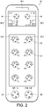
- FIG. 2 illustrates the slave device 40 as a specific example of the slave device applied to the industrial network 1.
- the slave device 40 is a terminal in the industrial network 1, and includes two Ethernet ports (communication ports) for connection with the industrial network 1.
- an Ethernet connector 41 and an Ethernet connector 42 for connection with the communication cables 70 are respectively provided.
- the slave device 40 of the example is a terminal also referred to as an I/O control apparatus. Multiple devices, such as sensors or controllers, may be connected to the slave device 40 that is an I/O control apparatus.
- the slave device 40 includes multiple device ports for such devices, each of which is provided with a device connector 43.
- the slave device 40 includes eight device ports, and symbols P1 to P8 are labeled to the sides of the respectively corresponding device connectors 43.
- the slave device 40 may supply power of a required voltage to the device through the device port.
- the slave device 40 may receive a voltage signal from the device through the device port.
- the slave device 40 may conduct communication with the device through the device port in accordance with a predetermined communication specification.
- a predetermined communication specification I/O-LINK may be adopted.
- the slave device 40 further includes a power input port PWR_IN and a power output port PWR_OUT.
- a power input connector 44 and a power output connector 45 are respectively provided at the power input port PWR IN and the power output port PWR_OUT.
- the respective connectors are disposed on the front surface of the slave device 40.
- the surface on the front surface side of the slave device 40 is referred to as a panel surface.
- FIG. 2 merely schematically illustrates each of the Ethernet connector 41, the Ethernet connector 42, the device connectors 43, the power input connector 44, and the power input connector 45, and does not serve to accurately depict the shapes thereof.
- a lamp 461 which may notify the occurrence of an operational abnormality in the slave device 40 is disposed.
- an indicator 462 that may display a status of the operation of the slave device 40, or a communication status via the Ethernet port ETN1, the Ethernet ETN2, etc., is disposed.
- the indicator 462 includes the following: a lamp U/IN_PWR displaying a status of power supply to the slave device 40 through the power input port PWR_IN; a lamp OUT PWR displaying a status of power output through the power output port PWR_OUT.
- a lamp L/A_ETH1 displaying the communication status via the Ethernet port ETN1; a lamp L/A_ETH2 displaying the communication status via the Ethernet port ETN2; a network abnormality display lamp NS for displaying a communication status (network status) relating to whether the communication is normal; and a device abnormality display lamp MS for displaying a device abnormality of the slave device 40 itself.
- a device status display lamp 463 is disposed on the panel surface of the slave device 40.
- the device status display lamp 463 is adjacent to the device connector 43 of each device port, and displays the connection of a device to the each device port or the status of the connected device.
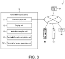
- FIG. 3 is a block diagram illustrating a configuration of the terminal monitoring device 10 according to Embodiment 1.
- the terminal monitoring device 10 according to Embodiment 1 includes a communication unit 11, a display unit 12, an instruction reception unit 13, a terminal information acquisition unit 14, and a terminal list screen generation unit 151.
- the communication unit 11 is a communication interface that conducts communication with the master device 20 or the respective terminals forming the industrial network 1.
- the display unit 12 has a display 121, and transmits information to the administrator, etc., of the industrial network 1 through a screen displayed on the display 121.
- Multiple communication ports for connection with the industrial network may also be provided at the communication unit 11. In such case, by switching the communication port, it is possible to switch the terminal monitoring device 10 to be connected to any of multiple industrial networks.
- the instruction reception unit 13 is a user interface of receiving an instruction from the administrator, etc.
- a conventional technique may be applied as appropriate.
- a touch panel display integrated with the display 121 may be applied.
- technologies such as a keyboard, a moving button (so-called "arrow key"), a mouse, a track ball, a stylus, etc., may also be adopted.
- the terminal information acquisition unit 14 is a functional block acquiring terminal information including the addresses, the type information, and the communication status information from the respective terminals forming the industrial network 1 through the communication unit 11.
- Examples of the respective terminals may include the slave devices 40 which are I/O control apparatuses, the slave devices 50 or other slave devices, and the ring supervisors 60.
- the terminal information in the case where the terminal is the ring supervisor 60 may also include the addresses of the slave devices forming the ring network 2 managed by the ring supervisor 60.
- the terminal list screen generation unit 151 is a functional block generating a terminal list screen P1 based on the terminal information and displaying the terminal list screen P1 on the display unit 12.
- the terminal list screen P1 in Embodiment 1 is described in the following.
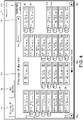
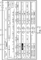
- FIG. 4 illustrates the terminal list screen P1 generated by the terminal list screen generation unit 151 and displayed on the display 121 of the display unit 12. On the terminal list screen P1, the following is displayed.
- "Ethernet/IP Monitor" is shown.
- a screen selection box Bp indicating that there are the terminal list screen P1 and a screen other than the terminal list screen P1.
- a screen selection box Bp By selecting a screen using the screen selection box Bp, it is easy for the administrator, etc., to select and display a desired screen on the display 121.
- a screen selection box displaying the terminal list screen P1 and shown as "Ethernet/IP Monitor" is selected.
- a time text expression Ctm A configuration read box Br (information acquisition instruction box) used for an operation for reading the configuration of the industrial network 1.
- the function of the configuration read box Br will be described in the following.
- a selection box Bn representing each terminal in the industrial network 1. With the administrator, etc., selecting the terminal by using the selection box Bn representing the terminal, the detailed information relating to the terminal can be displayed on the display 121 as a separate screen and acquired.
- the administrator, etc. operates the port list box Spt and selects the communication port from the list of the multiple communication ports of the communication unit 11 that is displayed.
- the terminal list screen P1 relating to the industrial network to which the communication port is connected is generated by the terminal list screen generation unit 151, and is displayed on the display 121 of the display unit 12.
- the selection boxes Bn representing the terminals are disposed side-by-side on the terminal list screen P1 in the order of Internet protocol (IP) addresses.
- IP Internet protocol
- a selection box Bn representing a specific terminal is disposed at the same position.
- the connection of terminals, such as the slave devices may be modified, or the power of an apparatus not in use may be turned off.
- the administrator viewing the terminal list screen P1 may easily grasp the conditions of the terminals in the industrial network 1.
- the terminal list screen P1 is configured to be capable of page-feeding.
- page feeding boxes Bpg respectively used for feeding the page forward and backward are provided at two ends of the lower part of the terminal list screen P1.
- a text expression Cmd of the model information of the terminal and a text expression Cip of the IP address are displayed. Accordingly, the administrator, etc., can easily recognize which apparatus model the terminal in the industrial network that is specified by the IP address is.
- the selection box Bn representing the terminal is provided with an expression representing the properties of the terminal.
- an expression representing the properties of the terminal a figure expression Prm representing that the terminal is the ring supervisor 60 and a figure expression Prs representing that the terminal is a slave device forming the ring network 2 are displayed.
- a terminal is shown as not a terminal forming the ring network 2. Accordingly, the administrator, etc., can easily recognize the presence of the ring network 2 constructed in the industrial network 1 and the apparatuses forming the ring network 2.
- an image expression which is like a lamp and expresses the status of the terminal is displayed in the selection box Bn representing the terminal.
- a machine status image Lms is displayed.
- a machine status on whether the terminal itself suffers from an apparatus abnormality is represented in colors.
- a communication status image expression Lns is displayed.
- the network status on whether the communication of the terminal is abnormal is represented in colors. Accordingly, the administrator, etc., can view through these terminals and easily recognize whether each terminal in the industrial network 1 is abnormal.
- the terminal list screen P1 is generated according to the following.
- the instruction reception unit 13 detects that the administrator, etc., operates the configuration read box Br.
- the terminal information acquisition unit 14 performs broadcasting to the industrial network 1 through the communication unit 11.
- Each terminal in the industrial network 1 receiving broadcasting returns a telegraphic message with IP address and model information to the terminal monitoring device 10.
- the terminal information acquisition unit 14 acquires a portion of the apparatus information of each terminal from the telegraphic messages.
- the terminal list screen generation unit 15 generates, based on the apparatus information, the terminal list screen P1 in which the selection box Bn representing each terminal is disposed.
- the terminal information acquisition unit 14 may inquire the terminal about the addresses of the slave devices forming the ring network 2 and receives the result of the inquiry.
- the terminal list screen generation unit 151 adds the figure expression Prm indicating that the terminal is the ring supervisor 60, the figure expressions Prs indicating that the terminals are the slave devices forming the ring network 2 to the selection boxes Bn representing the terminals.
- the terminal information acquisition unit 14 periodically inquires about and receives the status of the terminal from each terminal whose IP address is acquired.
- the terminal list screen generation unit 151 determines the colors of the machine status image expression Lms and the communication status image expression Lns of the selection box Bn representing the terminal. Accordingly, the administrator can learn, in a real-time manner, the status of each terminal on the display 121.
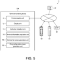
- FIG. 5 is a block diagram illustrating a configuration of the terminal monitoring device 10A.
- the terminal monitoring device 10A includes the communication unit 11, the display unit 12, the instruction reception unit 13, the terminal information acquisition unit 14, the terminal list screen generation unit 151, and a ring configuration screen generation unit 152.
- the terminal information acquired by the terminal information acquisition unit 14 of Embodiment 2 includes the contents of the terminal information according to Embodiment 1.
- the terminal information acquired by the terminal information acquisition unit 14 includes the information relating to the configuration of the ring network 2 managed by the ring supervisor 60 and the communication status information among the terminals in the ring network 2.
- the ring configuration screen generation unit 152 is a functional block generating the ring configuration screen P2 based on the terminal information and displaying the ring configuration screen P2 on the display unit 12.
- the ring configuration screen P2 in Embodiment 2 is described in the following.
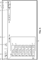
- FIG. 6 illustrates the ring configuration screen P2 generated by the ring configuration screen generation unit 152 and displayed on the display 121 of the display unit 12.
- the ring configuration screen P2 is a screen illustrating the configuration of a specific ring network 2 in the industrial network 1. On the ring configuration screen 2, the following is displayed.
- "DLR Monitor" is shown.
- the screen selection box Bp indicating that there are the ring configuration screen P2 and a screen other than the ring configuration screen P2.
- the screen displayed on the display 121 is transitioned to the ring configuration screen P2.
- the administrator, etc. performs an operation of selecting "Ethernet/IP Monitor” from the screen selection box Bp on the ring configuration screen P2
- the screen displayed by the display 121 is transitioned to the terminal list screen P1. Accordingly, it is possible to easily switch to the desired screen.
- the time text expression Ctm The configuration read box Br.
- the above are the same as the previous embodiment.
- An address list box Sip indicating the IP address of the ring supervisor 60 of the ring network 2 that is selected.
- the administrator, etc. operates the address list box Sip to select the IP address of the specific ring supervisor 60 from the list of the IP addresses of the ring supervisors 60 that are displayed. Then, the administrator, etc., can select the specific ring network 2 and display the specific ring network 2 on the ring configuration screen P2.
- the detailed information relating to the terminal can be displayed on the display 121 as a separate screen and acquired.
- the selection boxes Bn representing the terminals of the ring network 2 are connected by a connection line Pcb indicating the connection relationship among the terminals in a connection order inside the ring network 2, and are disposed side-by-side on the ring configuration screen P2. Therefore, the administrator, etc., can easily have a grasp of the configuration of the ring network 2 according to the ring configuration screen P2. This point is different from the terminal list screen P1 in which the selection boxes Bn representing the terminals are disposed in the order of IP addresses.
- the text expression Cmd of the model information of the terminal, the text expression Cip of the IP address, the machine status image expression Lms, and the communication status image expression Lns displayed in the selection box Bn representing the terminal are the same as the above.
- the figure expression Prm added to the selection box Bn representing the terminal and illustrating that the terminal is the ring supervisor 60 is the same as the above.
- the following method can be applied.
- the administrator, etc. performs an operation of selecting the selection box Bn illustrating the ring supervisor 60 on the terminal list screen P1 and representing the terminal.
- the screen displayed on the display 121 is transitioned to the ring configuration screen P2 illustrating the ring network 2 managed by the ring supervisor 60.
- the image expression Prm indicating that the terminal is the ring supervisor 60 is added for the ring supervisor 60, so as to be displayed in an easily understandable manner. Accordingly, with such transition, the administrator can easily select and display the ring network 2 as the target.
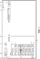
- FIG. 7 is a view illustrating the ring configuration screen P2 when an abnormality, such as communication interruption, occurs between specific terminals of the ring network 2.
- an abnormality such as communication interruption
- the ring configuration screen P2 is generated according to the following.
- the terminal information acquisition unit 14 acquires the apparatus information of each terminal present in the industrial network 1.
- the terminal information acquisition unit 14 inquires the target ring supervisor 60 about the configuration of the ring network 2 and receives the result of the inquiry. Based on such information, the ring configuration screen generation unit 152 disposes the selection boxes Bn of the terminals forming the ring network 2 in accordance with the configuration of the ring network 2.
- the terminal information acquisition unit 14 periodically inquires the ring supervisor 60 about the status of the ring network 2 and receives the status. Based on such information, if an abnormality, such as communication interruption, occurs between specific terminals, the ring configuration screen generation unit 152 adds the warning image expression Wr for this purpose.
- the ring network 2 has redundancy. Even if the communication interruption occurs at one place between the terminals, the communication of the terminals forming the ring network 2 is not interrupted. By making use of the redundancy, in the terminal monitoring device 10A, the communication abnormality between terminals in the ring network 2 can be displayed in a real-time manner on the ring configuration screen P2.
- the list of the IP addresses of the ring supervisors 60 that can be displayed by the address list box Sip of the ring configuration screen P2 is extracted and generated based on the type information in the terminal information.
- FIG. 8 is a block diagram illustrating a configuration of the terminal monitoring device 10B.
- the terminal monitoring device 10B includes the communication unit 11, the display unit 12, the instruction reception unit 13, the terminal information acquisition unit 14, the terminal list screen generation unit 151, a communication status screen generation unit 153, a cable diagnosis control unit 16, and a lamp lighting control unit 17.
- the terminal information acquired by the terminal information acquisition unit 14 of Embodiment 3 includes the contents of the terminal information according to Embodiment 1. Additionally, in the case where the terminal is the slave device 40, the terminal information acquired by the terminal information acquisition unit 14 may also include detailed information relating to communication executed by the slave device 49.
- the cable diagnosis control unit 16 is a functional block that instructs the slave device 40 to execute a cable diagnosis, and acquires the result.
- the communication status generation unit 153 is a functional block generating and displaying the communication status screen P3 on the display unit 12 based on the result of execution of the cable diagnosis and the terminal information.
- the communication status screen P3 in Embodiment 3 is described in the following.
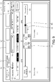
- FIG. 6 illustrates the communication status screen P3 generated by the communication status screen generation unit 153 and displayed on the display 121 of the display unit 12.
- the communication status screen P3 is a screen illustrating detailed information regarding the communication status of a specific slave device 40. On the communication status screen P3, the following is displayed.
- the model name and the characters indicating that the model is being monitored are described as "GI-xxxxxxx Monitor". Accordingly, the administrator, etc., can clearly recognize that the screen is a screen illustrating the information relating to the slave device 40 of a specific model.
- "Ethernet/IP statistical information" is described for the communication status screen P3.
- the address list box Sip indicating the IP address of the selected slave device 40.
- An image expression Pst illustrating a list of the statuses of the slave devices 40.
- the image expression Pst imitates the expression of each lamp of the indicator 462 provided at the slave device 40, and displays synchronically with the indicator 462 of the slave device 40.
- the administrator, etc. can grasp the status of the slave device 40 by using the terminal monitoring device 10B without checking the actual slave device 40.
- a lamp lighting instruction box Bih Details in this regard will be described in the following.
- the cable information text expression Ccb displays the status of the communication cable 70 connected to each Ethernet port.
- the administrator, etc. can recognize that the content displayed on the communication status screen P3 is information relating to the slave device 40 of such model at a glance.
- the image expression Pet imitating each Ethernet connector of the slave device 40, the administrator, etc. can recognize that the content displayed on the communication status screen P3 is information specifically related to the Ethernet port of the slave device 40 at a glance.
- the displayed information being the information of which Ethernet port connected to the cable can be recognized at a glance.
- the distance from the Ethernet connector 42 to the place where the failure occurs is displayed as a distance text expression Cds. Accordingly, in the case where a failure of the communication cable 70 occurs, the administrator, etc., can recognize the fact that the failure occurs, the content of the failure, and the place where the failure occurs on the communication status screen P3 in a real-time manner. It is noted that, as the information of the failure of the communication cable 70, a failure of short circuit is also displayed in addition to a disconnection.
- An Ethernet port text expression Cet which is information regarding the communication status of each of the Ethernet port ETN1 and the Ethernet port ETN2.
- the information regarding the communication status is the statistic information, etc., relating to communication errors, and is various information relating to the communication through each Ethernet port held by the slave device 40.
- the communication status screen P3 is generated according to the following.
- the instruction reception unit 13 receives an instruction of transitioning to the communication status screen P3 from the administrator, etc. Cases of such instruction are provided in the following:
- the terminal information acquisition unit 14 inquires the slave device 40 about the terminal information relating to communication through the communication unit 11.
- the communication status screen generation unit 153 generates the communication status screen P3 based on such information, and displays the communication status screen P3 on the display unit 12.
- the cable diagnosis control unit 16 makes the slave device 40 execute a cable diagnosis with respect to the communication cable 70 connected to the Ethernet port that is abnormal. By doing so, the cable diagnosis control unit 16 receives the result of the cable diagnosis from the slave device 40.
- the result of the cable diagnosis may be any of normal, disconnected, short-circuited.
- the result of cable diagnosis may include a distance from the slave device 40 to the location of the failure.
- the communication status screen generation unit 153 Based on the information, the communication status screen generation unit 153 generates the communication status screen P3 including the information of the failure of the communication cable and displays the communication status screen P3 on the display unit 12. Through simply displaying the communication status screen P3, the administrator, etc., can learn the occurrence of the failure of the communication cable 70 and the content thereof without specifically sending an instruction with respect to the slave device 40.
- the inquiry about the terminal information for generating the communication status screen P3 is repetitively executed when the communication status screen P3 is displayed, and on the display status screen P3, detailed information regarding the communication status of the specific slave device 40 is displayed in a real-time manner.
- the list of the IP addresses of the slave devices 40 that can be displayed by the address list box Sip of the communication status screen P3 is generated by extracting the type information in the terminal information.
- the communication status screen P3 turns on the lamp 461 of a specific slave device 40 that displays information. Then, through a further operation by the administrator, etc., afterwards, the lighting is turned off.
- the lamp lighting control unit 17 instructs the slave device 40 to turn on or turn off the lamp 461 through the communication unit 11.
- the lighting described herein also includes blinking of the lamp 461.
- the administrator, etc. can easily learn at which place of the field the slave device 40 displayed on the communication status screen P3 is present. Specifically, in the communication status screen P3, in the case where an abnormality such as a disconnection, etc., of the communication cable 70 or an abnormality of the slave device 40 itself is reported, by operating the lamp lighting instruction box Bih, the location where the abnormality occurs can be directly recognized.
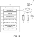
- FIG. 10 is a block diagram illustrating a configuration of the terminal monitoring device 10C.
- the terminal monitoring device 10C includes the communication unit 11, the display unit 12, the instruction reception unit 13, the terminal information acquisition unit 14, the terminal list screen generation unit 151, a device connection status screen generation unit 154, and the lamp lighting control unit 17.
- the terminal information acquired by the terminal information acquisition unit 14 of Embodiment 4 includes the contents of the terminal information according to Embodiment 1. Additionally, in the case where the terminal is a slave device 40 that is an I/O control apparatus, the terminal information acquired by the terminal information acquisition unit 14 may include detailed information illustrating the connection status with a device at each device port.
- the device connection status screen generation unit 154 is a functional block generating the device connection status screen P4 based on the terminal information and displaying the device connection status screen P4 on the display unit 12.
- the device connection status screen P4 in Embodiment 4 is described in the following.
- FIG. 11 illustrates the device connection status screen P4 generated by the device connection status screen generation unit 154 and displayed on the display 121 of the display unit 12.
- the device connection status screen P4 is a screen illustrating detailed information regarding the connection status of the slave device 40 as an I/O control apparatus with a device. On the device connection status screen P4, the following is displayed.
- the text expression Cp4 is the same as the text expression Cp3 in the communication status screen P3.
- the slave information selection box Bsi showing there are the device connection status screen P4 and the screen other than the device connection status screen P4 regarding the specific slave device 40.
- a screen may further display information of other types without being limited to the example.
- slave information selection box Bsi By selecting the screen using the slave information selection box Bsi, it is easy for the administrator, etc., to select and display a screen displaying desired information regarding the specific slave device 40 on the display 121. By making such slave information selection box Bsi common among various screens regarding the specific slave device 40, the administrator, etc., may make a selection easily.
- the time text expression Ctm The port list box Spt.
- the administrator, etc. can recognize that the content displayed by the device connection status screen P4 is the information relating to the slave device 40 of such model at a glance.
- the administrator, etc. can recognize that the content displayed by the device connection status screen P4 is specifically related to the device port of the slave device 40 at a glance.
- a device port information text expression Cpi being associated with each device connector 43 and displayed, which device port being related to the information illustrated in the device port information text expression Cpi can be recognized at a glance.
- the device port information text expression Cpi may include information as follows: an expression relating to setting of a connection mode with the device; an expression relating to the connection status with the device; and an expression relating to a model name of the connected device.
- the administrator, etc. can easily grasp the detailed information regarding devices set to and connected with the slave device 40 as an I/O control apparatus in this way through display of the display 121.
- the device connection status screen P4 is generated according to the following.
- the instruction reception unit 13 receives an instruction of transitioning to the device connection status screen P4 from the administrator, etc. Cases of such instruction are provided in the following:
- the terminal information acquisition unit 14 inquires the slave device 40 about the terminal information relating to the device connection status through the communication unit 11.
- the device connection status screen generation unit 154 generates the device connection status screen P4 based on such information, and displays the device connection status screen P4 on the display unit 12.
- the inquiry about the terminal information for generating the device connection status screen P4 is repetitively executed when the device connection status screen P4 is displayed. Then, on the device connection status P4, the detailed information illustrating the connection status with the device at each device port of the specific slave device 40 is displayed in a real-time manner.
- the functional blocks (specifically, the instruction reception unit 13, the terminal information acquisition unit 14, the terminal list screen generation unit 151, the ring configuration screen generation unit 152, the communication status screen generation unit 153, the device connection status screen generation unit 154, the cable diagnosis control unit 16, the lamp lighting control unit 17) of the terminal monitoring device 10, 10A, 10B, 10C may be realized by using logic circuits (hardware) formed in integrated circuits (IC chips), etc., and may also be realized by software.
- the terminal monitoring device 10, 10A, 10B, 10C includes a computer executing the commands of a program, which is software, that realizes the respective functions.
- the computer for example, includes one or more processor as well as a computer-readable recording medium storing the program.
- the processor reads the program from the recording medium and executes the program, thereby achieving the objective of the invention.
- a central processing unit can be used, for example.
- a "non-transient tangible medium” such as a device, a disc, a card, a semiconductor memory, a programmable logic circuit, in addition to a read only memory (ROM), can be used.
- the computer may further include a random access memory (RAM) which expands the program.
- the program may also be supplied to the computer via any transmission medium (such as a communication network or broadcast waves) able to transmit the program.
- An aspect of the invention can also be realized in the form of a data signal embedded in a carrier wave, in which the program is embodied by electronic transmission.
- a terminal monitoring device is connected to a network including slave devices, as terminals, controlled by a master device.
- the terminal monitoring device includes: a display unit, displaying a screen; a terminal information acquisition unit, acquiring terminal information including each address, type information, and communication status information from the terminals; and a terminal list screen generation unit, generating, based on the terminal information, a terminal list screen on which selection boxes representing the terminals and displaying the terminal information are disposed side by side, and displaying the terminal list screen on a display unit.
- the terminal monitoring device allowing the administrator, etc., to easily verify the statuses of the slave devices connected to the industrial network through the terminal list screen can be realized.
- the terminal monitoring device may also include a configuration in which an arrangement order of the selection boxes on the terminal list screen follows an arrangement order of the addresses, and, in the arrangement order of the addresses, when a number is vacant, a position of the number that is vacant is displayed as a vacant field where the selection box is not disposed.
- the terminal monitoring apparatus allowing the administrator, etc., to easily grasp the statuses of the terminals in the industrial network even in the case where the connection of the terminal, such as the slave device, is changed, or the power of an apparatus not in use is turned off can be realized.
- the terminal monitoring device may also include a configuration in which a configuration read box is disposed on the terminal list screen, and the configuration read box receives an instruction of acquiring the terminal information provided to the terminal information acquisition unit.
- the terminal list screen can be updated at the timing when the administrator, etc., operates the configuration read box.
- the terminal monitoring device may also include a configuration in which the network is provided with a partial network of a ring topology in which multiple slave devices are connected through a ring supervisor, the partial network being formed by the slave devices and the ring supervisor.
- the terminal information includes: addresses of the slave devices forming the partial network and managed by the ring supervisor, and communication status information with the terminal in the partial network.
- the terminal monitoring device further includes a ring configuration screen generation unit generating, based on the terminal information, a ring configuration screen in which selection boxes representing the terminals forming the partial network and displaying the terminal information are arranged in a connection order of the terminals, and displaying the ring configuration screen on the display unit.
- the terminal monitoring device allowing the administrator, etc., to easily grasp the configuration of the partial network of the ring topology in the industrial network through the ring configuration screen can be realized.
- the terminal monitoring device may also include a configuration in which, when the communication status information comprises information illustrating a communication abnormality between specific terminals in the partial network, an expression illustrating the communication abnormality is displayed between the selection boxes representing the specific terminals on the ring configuration screen.
- the terminal monitoring device allowing the administrator, etc., to, when a communication abnormality occurs between specific terminals, easily grasp the occurrence of the abnormality and the specification of the position of the abnormality can be realized.
- the terminal monitoring device may also include a configuration in which, on the terminal list screen, when the selection box representing the terminal that is the ring supervisor is selected, the ring configuration screen is displayed.
- the terminal monitoring device allowing the administrator, etc., to easily select the desired partial network of the ring topology and display the details of the partial network can be realized.
- the terminal monitoring device may also include a configuration in which the terminal information, in a case where the terminal is the slave device, includes information of a communication status relating to each of a plurality of communication ports of the slave device.
- the terminal monitoring device further includes: a communication status screen generation unit, generating, based on the terminal information, a communication status screen illustrating a communication status relating to each of the communication ports of the slave device, and displaying the communication status screen on the display unit; and a cable diagnosis control unit, making the slave device execute a diagnosis of a communication cable connected to a specific communication port and acquiring a result of the diagnosis.
- information of the communication status regarding the slave device comprises information illustrating a communication abnormality of the specific communication port of the slave device
- an expression illustrating a status of the communication cable based on the result of the diagnosis acquired from the cable diagnosis control unit is displayed on the communication status screen regarding the slave device.
- the terminal monitoring device allowing the administrator, etc., to easily grasp the status of the communication cable connected with the specific slave device in the industrial network through the communication status screen can be realized.
- the terminal monitoring device may also include a configuration in which, when a selection box representing the terminal that is the slave device is selected on the terminal list screen or the ring configuration screen, the communication status screen regarding the slave device is displayed.
- the terminal monitoring device allowing the administrator, etc., to easily select a specific slave device from the industrial network and display the details of the communication status of the specific slave device can be realized.
- the terminal monitoring device may also include a configuration in which, the terminal information, in a case where the terminal is the slave device in which a plurality of device ports for connection with devices are provided, includes information relating to communication with the device at each of the device ports of the slave device.
- the terminal monitoring device further includes a device connection status screen generation unit, generating, based on the terminal information, a device connection status screen illustrating connection statuses of the devices at the device ports of the slave device, and displaying the device connection status screen on the display unit.
- the terminal monitoring device allowing the administrator, etc., to easily grasp the statuses of the device ports in the slave device with multiple device ports in the industrial network through the device connection status screen can be easily realized.
- the terminal monitoring device may also include a configuration in which, when a selection box representing the terminal that is the slave device is selected on the terminal list screen or the ring configuration screen, the device connection status screen regarding the slave device is displayed.
- the terminal monitoring device allowing the administrator, etc., to easily select the specific slave device with multiple device ports from the industrial network and display the details of the statuses of the device ports can be realized.
- the terminal monitoring device may also include a configuration which further includes a lamp lighting control unit which makes the slave device turn on a lamp mounted on the slave device.
- a lighting instruction box is disposed on the communication status screen or the device connection status screen, and the lighting instruction box receives a lamp lighting instruction provided for the slave device displayed on the screen to the lamp lighting control unit.
- the terminal monitoring device allowing the administrator, etc., to easily find the specific slave device of the industrial network illustrated in the communication status screen or the device connection status screen can be realized.
Landscapes
- Engineering & Computer Science (AREA)
- Physics & Mathematics (AREA)
- General Physics & Mathematics (AREA)
- Automation & Control Theory (AREA)
- Computer Networks & Wireless Communication (AREA)
- Signal Processing (AREA)
- Environmental & Geological Engineering (AREA)
- Human Computer Interaction (AREA)
- Small-Scale Networks (AREA)
- Programmable Controllers (AREA)
- Testing And Monitoring For Control Systems (AREA)
- Data Exchanges In Wide-Area Networks (AREA)
Applications Claiming Priority (2)
| Application Number | Priority Date | Filing Date | Title |
|---|---|---|---|
| JP2020043753A JP7484252B2 (ja) | 2020-03-13 | 2020-03-13 | 端末監視装置 |
| PCT/JP2021/007601 WO2021182147A1 (ja) | 2020-03-13 | 2021-03-01 | 端末監視装置 |
Publications (2)
| Publication Number | Publication Date |
|---|---|
| EP4120635A1 true EP4120635A1 (de) | 2023-01-18 |
| EP4120635A4 EP4120635A4 (de) | 2024-04-24 |
Family
ID=77670533
Family Applications (1)
| Application Number | Title | Priority Date | Filing Date |
|---|---|---|---|
| EP21768715.1A Pending EP4120635A4 (de) | 2020-03-13 | 2021-03-01 | Endgeräteüberwachungsvorrichtung |
Country Status (5)
| Country | Link |
|---|---|
| US (1) | US12372938B2 (de) |
| EP (1) | EP4120635A4 (de) |
| JP (1) | JP7484252B2 (de) |
| CN (1) | CN115104289B (de) |
| WO (1) | WO2021182147A1 (de) |
Families Citing this family (1)
| Publication number | Priority date | Publication date | Assignee | Title |
|---|---|---|---|---|
| JP7735905B2 (ja) * | 2022-03-14 | 2025-09-09 | オムロン株式会社 | 端末制御装置、端末制御装置の制御方法、端末制御プログラム、スレーブ装置、及びマスタ装置 |
Family Cites Families (22)
| Publication number | Priority date | Publication date | Assignee | Title |
|---|---|---|---|---|
| US6856627B2 (en) * | 1999-01-15 | 2005-02-15 | Cisco Technology, Inc. | Method for routing information over a network |
| JP2002123307A (ja) | 2000-10-17 | 2002-04-26 | Toshiba Mach Co Ltd | 工作機械の監視システムおよび数値制御装置 |
| JP4494687B2 (ja) | 2001-09-27 | 2010-06-30 | 株式会社キーエンス | センサ管理装置およびセンサ管理プログラム |
| JP2004133806A (ja) | 2002-10-11 | 2004-04-30 | Omron Corp | プログラマブル表示器及びモニタ方法並びに画面作成装置 |
| JP4153771B2 (ja) * | 2002-10-17 | 2008-09-24 | 株式会社東芝 | 伝送システムとその監視制御装置およびプロテクション機能の設定更新方法 |
| US8590033B2 (en) * | 2008-09-25 | 2013-11-19 | Fisher-Rosemount Systems, Inc. | One button security lockdown of a process control network |
| US7990897B2 (en) * | 2009-03-11 | 2011-08-02 | Sony Corporation | Method and apparatus for a wireless home mesh network with network topology visualizer |
| CN102136928B (zh) * | 2010-07-02 | 2013-10-09 | 华为技术有限公司 | 拓扑发现方法及装置 |
| JP5195955B2 (ja) * | 2011-03-15 | 2013-05-15 | オムロン株式会社 | 設計支援システム |
| WO2012124392A1 (ja) | 2011-03-15 | 2012-09-20 | オムロン株式会社 | ネットワークシステム、マスター装置およびネットワークシステムの制御方法 |
| JP2014157542A (ja) | 2013-02-18 | 2014-08-28 | Nec Personal Computers Ltd | 端末装置および装置のプログラム |
| US11067475B2 (en) * | 2013-04-01 | 2021-07-20 | United States Of America As Represented By The Secretary Of The Army | Bedload transport methodology and method of use |
| JP6127755B2 (ja) * | 2013-06-13 | 2017-05-17 | オムロン株式会社 | 情報処理装置、情報処理装置の制御方法および制御プログラム |
| JP6378185B2 (ja) | 2013-09-03 | 2018-08-22 | フェリカネットワークス株式会社 | 情報処理端末、及び情報処理方法 |
| ES2770797T3 (es) * | 2015-01-23 | 2020-07-03 | Geely Holding Group Co Ltd | Terminales móviles, equipo terminal combinado, y método para control conjunto |
| JP2017108511A (ja) | 2015-12-08 | 2017-06-15 | 株式会社東芝 | 監視装置、監視方法、監視プログラム及び監視システム |
| JP2018011147A (ja) * | 2016-07-12 | 2018-01-18 | オムロン株式会社 | 情報処理装置、情報処理プログラムおよび情報処理方法 |
| JP2018107761A (ja) * | 2016-12-28 | 2018-07-05 | 日本電気株式会社 | 運用管理装置、システムおよび方法 |
| JP6798605B2 (ja) * | 2017-03-06 | 2020-12-09 | 富士通株式会社 | 監視処理プログラム、監視処理方法及び監視装置 |
| JP6882059B2 (ja) * | 2017-05-12 | 2021-06-02 | キヤノン株式会社 | プログラム、方法、及び装置 |
| JP2019169089A (ja) | 2018-03-26 | 2019-10-03 | オムロン株式会社 | ネットワーク管理装置、管理方法、管理プログラムおよび記録媒体 |
| JP6922814B2 (ja) * | 2018-03-27 | 2021-08-18 | オムロン株式会社 | サポート装置、サポートプログラム、設定方法 |
-
2020
- 2020-03-13 JP JP2020043753A patent/JP7484252B2/ja active Active
-
2021
- 2021-03-01 US US17/798,304 patent/US12372938B2/en active Active
- 2021-03-01 WO PCT/JP2021/007601 patent/WO2021182147A1/ja not_active Ceased
- 2021-03-01 CN CN202180013756.8A patent/CN115104289B/zh active Active
- 2021-03-01 EP EP21768715.1A patent/EP4120635A4/de active Pending
Also Published As
| Publication number | Publication date |
|---|---|
| EP4120635A4 (de) | 2024-04-24 |
| US20230096483A1 (en) | 2023-03-30 |
| JP7484252B2 (ja) | 2024-05-16 |
| WO2021182147A1 (ja) | 2021-09-16 |
| CN115104289A (zh) | 2022-09-23 |
| US12372938B2 (en) | 2025-07-29 |
| CN115104289B (zh) | 2024-07-05 |
| JP2021145273A (ja) | 2021-09-24 |
Similar Documents
| Publication | Publication Date | Title |
|---|---|---|
| US9411614B2 (en) | Input/output devices having reconfigurable functionality | |
| US9483928B2 (en) | Input/output circuits and devices having physically corresponding status indicators | |
| US8264852B2 (en) | Pluggable bases with different levels of redundancy and method for same | |
| CN107592187B (zh) | 一种基于双通道表决系统的表决方法 | |
| CN102122157A (zh) | 保持原系统功能和性能的冗余架构控制系统和方法 | |
| US8943188B2 (en) | Automation network comprising network components that produce status messages | |
| CN103926853A (zh) | 一种可编程电阻输出装置和方法 | |
| CN112051827A (zh) | 一种基于列车网络的轴温监测系统的调试系统 | |
| EP4120635A1 (de) | Endgeräteüberwachungsvorrichtung | |
| EP3385828B1 (de) | Computerimplementiertes verfahren zum konfigurieren eines elektronischen relais | |
| KR20140141938A (ko) | Plc 시스템에서 통신모듈의 이중화 방법 | |
| CN112562553A (zh) | 一种液晶控制模块的测试系统及测试方法 | |
| CN107659517B (zh) | 一种基于本地管理的PoE交换机及管理系统 | |
| CN120045488A (zh) | 硬件控制系统、方法、装置、存储介质及电子设备 | |
| US20240264585A1 (en) | High Availability Networking Device | |
| US20240103498A1 (en) | Systems and methods of remotely controlling channel resets for input/output modules of industrial systems | |
| CN203930476U (zh) | 一种船用车令传送及执行装置 | |
| CN217155448U (zh) | 一种室外监测系统测试工装 | |
| CN214098423U (zh) | 一种无纸记录仪用主控模块 | |
| RU239471U1 (ru) | Беспроводной терминал сбора данных со станков с ЧПУ | |
| CN118606529B (zh) | 一种采煤作业的实时可视化方法及系统 | |
| JP2847957B2 (ja) | 増設システム | |
| JP2012129862A (ja) | 通信モジュール | |
| KR200363756Y1 (ko) | 계전기 원격 제어장치 | |
| CN223624339U (zh) | 一种配电终端运维装置 |
Legal Events
| Date | Code | Title | Description |
|---|---|---|---|
| STAA | Information on the status of an ep patent application or granted ep patent |
Free format text: STATUS: THE INTERNATIONAL PUBLICATION HAS BEEN MADE |
|
| PUAI | Public reference made under article 153(3) epc to a published international application that has entered the european phase |
Free format text: ORIGINAL CODE: 0009012 |
|
| STAA | Information on the status of an ep patent application or granted ep patent |
Free format text: STATUS: REQUEST FOR EXAMINATION WAS MADE |
|
| 17P | Request for examination filed |
Effective date: 20220810 |
|
| AK | Designated contracting states |
Kind code of ref document: A1 Designated state(s): AL AT BE BG CH CY CZ DE DK EE ES FI FR GB GR HR HU IE IS IT LI LT LU LV MC MK MT NL NO PL PT RO RS SE SI SK SM TR |
|
| DAV | Request for validation of the european patent (deleted) | ||
| DAX | Request for extension of the european patent (deleted) | ||
| REG | Reference to a national code |
Ref country code: DE Ref legal event code: R079 Free format text: PREVIOUS MAIN CLASS: H04L0012280000 Ipc: G05B0019042000 |
|
| A4 | Supplementary search report drawn up and despatched |
Effective date: 20240325 |
|
| RIC1 | Information provided on ipc code assigned before grant |
Ipc: H04L 43/0817 20220101ALI20240319BHEP Ipc: H04L 41/22 20220101ALI20240319BHEP Ipc: H04L 12/28 20060101ALI20240319BHEP Ipc: G05B 19/048 20060101ALI20240319BHEP Ipc: G05B 19/042 20060101AFI20240319BHEP |
|
| STAA | Information on the status of an ep patent application or granted ep patent |
Free format text: STATUS: EXAMINATION IS IN PROGRESS |
|
| 17Q | First examination report despatched |
Effective date: 20250612 |