EP4113183B1 - Greifvorrichtung für glasfaserkabel - Google Patents
Greifvorrichtung für glasfaserkabel Download PDFInfo
- Publication number
- EP4113183B1 EP4113183B1 EP20921467.5A EP20921467A EP4113183B1 EP 4113183 B1 EP4113183 B1 EP 4113183B1 EP 20921467 A EP20921467 A EP 20921467A EP 4113183 B1 EP4113183 B1 EP 4113183B1
- Authority
- EP
- European Patent Office
- Prior art keywords
- optical fiber
- fiber cable
- thin plate
- plate portion
- protrusion
- Prior art date
- Legal status (The legal status is an assumption and is not a legal conclusion. Google has not performed a legal analysis and makes no representation as to the accuracy of the status listed.)
- Active
Links
Images


Classifications
-
- G—PHYSICS
- G02—OPTICS
- G02B—OPTICAL ELEMENTS, SYSTEMS OR APPARATUS
- G02B6/00—Light guides; Structural details of arrangements comprising light guides and other optical elements, e.g. couplings
- G02B6/44—Mechanical structures for providing tensile strength and external protection for fibres, e.g. optical transmission cables
- G02B6/4439—Auxiliary devices
- G02B6/4471—Terminating devices ; Cable clamps
- G02B6/44785—Cable clamps
Definitions
- the present disclosure relates to an optical fiber cable holding device for holding an optical fiber cable.
- a tension member such as steel wire is disposed to prevent an optical fiber core from being stretched more than necessary, for the purpose of securing quality of the communication.
- the optical fiber cable is fixed to prevent bending and damage of optical fibers caused by movement of the optical fiber cable.
- Patent Literature 1 discloses that steel wire is suitable for the tension member.
- Patent Literature 2 discloses a mechanism for bending and press-contact of the tension member and a member for holding an end of a cable.
- a cable including a nonmetallic tension member is made of, for example, glass fiber or chemical fiber as a main material.
- the optical fiber cable is typically required to be housed and fixed in the closure for connection and the like.
- the optical fiber cable is fixed at two positions in the closure. At one of the two positions, the optical fiber cable is held by bending and pressure-contact of the tension member as disclosed in Patent Literature 2. At the other position, the optical fiber cable is held in such a manner that a cable jacket is sandwiched.
- the tension member may be damaged because the material of the tension member is fragile unlike a metal, and a holding method to fix the tension member itself is cannot be used. Therefore, the cable is required to be fixed only by the latter method; however, it is not possible to hold the cable with strength sufficient to fix the cable at the single position because large sandwiching force causes buckling deformation of the cable jacket and damages the optical fiber core.
- US 2007/261880 A1 discloses a prior art cable gripping device.
- the present disclosure is to solve the above-described issues, and an object of the present disclosure is to fix an optical fiber cable having a nonmetallic tension member in a closure without damaging the tension member and a core.
- the invention to solve the above-described issues is a method to fix an optical fiber cable having a nonmetallic tension member in a closure by using a holding band, and the holding band causes appropriate gripping force and appropriate frictional force to act on the cable, which enables fixing of the cable by holding at a single point and eliminates damage by press-contact of the nonmetallic tension member.
- an optical fiber cable holding device includes all the features specified in appended claim 1.
- FIG. 1 is a perspective view of a holding band according to the present disclosure.
- a holding band 1 according to the present disclosure functions as an optical fiber cable holding device, and includes a thin plate portion 10, a band-diameter adjuster 11, a binding mechanism portion 12, and protrusion fitting holes 13.
- the holding band 1 is manufactured by processing a metal such as stainless steel or a nonmetallic synthetic resin.
- the band-diameter adjuster 11 and the binding mechanism portion 12 housing the band-diameter adjuster 11 are connected and fixed to one end of the thin plate portion 10.
- the protrusion fitting holes 13 to be screwed onto protrusions of the band-diameter adjuster 11 are provided on the other end of the thin plate portion 10.
- the thin plate portion 10 can pass through the binding mechanism portion 12 by being wound, and the band-diameter adjuster 11 fitted to the protrusion fitting holes 13 is tightened to adjust a diameter of a rough circle formed by the thin plate portion 10 and to have a firm grip on an optical fiber cable 2.
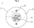
- Fig. 2 is a cross-sectional view of the optical fiber cable 2.
- the optical fiber cable 2 may have a self-supporting structure used for a case where the optical fiber cable 2 is laid between utility poles or is laid from a utility pole to a subscriber home. In this case, a supporting line is separated and the optical fiber cable 2 includes only a main body portion.
- the optical fiber cable 2 includes optical fibers 21, tension members 22 and a jacket 23 that is made of thermoplastic resin. Note that the configuration of the optical fiber cable 2 is not limited hereto as long as the optical fibers 21 are disposed inside an inner cavity 24.
- the optical fibers 21 transmit optical signals used for communication.
- the tension members 22 have a function to prevent the optical fibers 21 from being damaged by application of excessive tension on the optical fibers 21 in a longitudinal direction.
- the tension members 22 are each made of nonmetallic material such as glass fiber reinforced plastic, and does not cause electromagnetic induction.
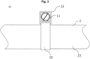
- Fig. 3 illustrates a configuration in which the optical fiber cable 2 is held by the holding band 1 in a closure.
- the holding band 1 is attached and wound around the optical fiber cable 2.
- the binding mechanism portion 12 has a shape engageable with a screwing tool such as a driver and a wrench, and can apply appropriate tightening pressure to the optical fiber cable 2.
- the optical fiber cable 2 is fixed only by the holding band 1.
- the tension members 22 themselves are not directly and mechanically press-fixed in the closure. Therefore, even when the tension members 22 are each made of a nonmetallic material, the tension members 22 are not damaged.
- fixing only by the holding band 1 makes it possible to improve work efficiency. Note that a member to be fixed to the closure may be attached to the holding band 1.
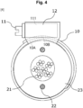
- Fig. 4 illustrates the holding configuration as viewed from the cable longitudinal direction, and illustrates a mechanism applying pressure to the optical fiber cable 2.
- One end 10A of the thin plate portion 10 is fixed to the binding mechanism portion 12.
- the other end 10B of the thin plate portion 10 is provided with the protrusion fitting holes 13, and the protrusion fitting holes 13 fit onto protrusions of a convex portion 111 of the band-diameter adjuster 11.
- the holding band 1 can have a firm grip on the optical fiber cable 2 such that the thin plate portion 10 comes into close contact with the optical fiber cable 2, and can uniformly apply the pressure in a circumferential direction.
- the holding band 1 can prevent buckling deformation of the optical fiber cable 2 and the jacket 23 in a case where the pressure is applied to the optical fiber cable 2 and the jacket 23 in one direction.
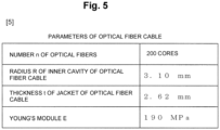
- Deformation of the jacket 23 occurred by applying the pressure to the optical fiber cable 2 causes contraction of an area of the inner cavity of the optical fiber cable 2.
- the plurality of optical fibers 21 stored in the optical fiber cable 2 closely contact with one another to generate excessive bending, which influences communication.
- a cross-sectional area S that is a limit for influence on the communication is determined by an expression (2).
- S p R ⁇ ⁇ R 2 Therefore, the pressure p to fix the optical fiber cable 2 can be increased to a value determined by an expression (3).
- p tE R ⁇ S / ⁇ R 2
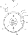
- Fig. 6 illustrates an example of a holding configuration according to the claimed invention.
- the holding band 1 according to the claimed invention further includes a thin plate elastic body 14, an elastic curved portion 15, and a protrusion 16.
- the gripping force expressed by the above-described expression (5) is realized by the thin plate elastic body 14 illustrated in Fig. 7 .
- the thin plate elastic body 14 includes the elastic curved portion 15 that is curved in an elliptical shape so as to externally contact with the jacket 23 of the optical fiber cable.
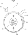
- the pressure occurring on an external contact point between the elastic curved portion 15 and the optical fiber cable 2 is increased by tightening the band-diameter adjuster 11, a curvature of the elastic curved portion 15 is reduced.
- the elastic curved portion 15 includes the protrusion 16 on a rear surface of the external contact point with the optical fiber cable 2.
- the protrusion 16 is caused to fit into one of the protrusion fitting holes 13 as illustrated in Fig. 8 , and the band-diameter adjuster 11 is not rotated any more.
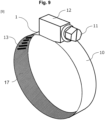
- a frictional force application portion 17 is added to a surface of the thin plate portion 10.
- the frictional force application portion 17 increases frictional force on a surface of the holding band 1 contacting with the optical fiber cable 2, which makes it possible to fix the optical fiber cable 2 in the closure when the tension in the cable longitudinal direction occurs on the optical fiber cable 2.
- the frictional force application portion 17 is realized by, for example, application of a friction material or formation of roughnesses on the thin plate portion.
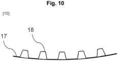
- Fig. 10 illustrates an example of holding protrusions 18 formed by the friction material added to the frictional force application portion 17 or the roughnesses provided on the thin plate portion 10.
- a shape of each of the holding protrusions 18 does not damage the jacket 23, and does not influence on the optical fibers 21 inside the optical fiber cable 2 and on communication. Further, the shape of each of the holding protrusions 18 may have a height smaller than a thickness of the jacket of the optical fiber cable 2, and may be a symmetric protrusion or may be an asymmetric shape to bite into the jacket 23, which is deformed due to the tension applied in the longitudinal direction.
- the present disclosure is applicable to information and communication industry.
Landscapes
- Physics & Mathematics (AREA)
- General Physics & Mathematics (AREA)
- Optics & Photonics (AREA)
- Light Guides In General And Applications Therefor (AREA)
- Mechanical Coupling Of Light Guides (AREA)
Claims (4)
- Vorrichtung zum Halten eines optischen Glasfaserkabels, umfassend:- einen Dünnplattenabschnitt (10), der durch Biegen einer rechteckigen Dünnplatte in Längsrichtung in eine annähernd kreisförmige Form ausgebildet ist, um den Außenumfang eines optischen Glasfaserkabels (2) zu halten;- einen Bindemechanismusabschnitt (12), der an einem Ende des Dünnplattenabschnitts (10) befestigt ist und eingerichtet ist, den um das optische Glasfaserkabel (2) herumgewickelten Dünnplattenabschnitt (10) an dem einen Ende des Dünnplattenabschnitts (10) zu binden;- Vorsprungsaufnahmelöcher (13), die an dem anderen Ende des um das optische Glasfaserkabel (2) herumgewickelten Dünnplattenabschnitts (10) vorgesehen sind; und- einen Banddurchmessereinsteller (11), der an dem Bindemechanismusabschnitt (12) befestigt ist, einen Banddurchmessereinstellvorsprung (111) aufweist, welcher jeweils in eines der Vorsprungsaufnahmelöcher (13) einsetzbar ist, und eingerichtet ist, durch Wechsel von einem Loch zu einem anderen Loch der Vorsprungsaufnahmelöcher (13) für das Einsetzen auf den Banddurchmessereinstellvorsprung (111), den Durchmesser der annähernd kreisförmigen Form einzustellen,dadurch gekennzeichnet, dassder Dünnplattenabschnitt (10) einen Mechanismus aufweist, um den vom Dünnplattenabschnitt (10) auf das optische Glasfaserkabel (2) ausgeübten Druck auf einen vorbestimmten Wert oder weniger zu begrenzen,wobei der Dünnplattenabschnitt (10) einen Dünnplattenelastikkörper (14) umfasst,wobei der Dünnplattenelastikkörper (14) einen elastischen Krümmungsabschnitt (15) aufweist, welcher so gekrümmt ist, dass er in Richtung des optischen Glasfaserkabels (2) vorsteht und außen mit ihm in Kontakt kommt,wobei der elastische Krümmungsabschnitt (15) auf einer Rückseite, die nicht mit dem optischen Glasfaserkabel (2) in Berührung kommt, einen Vorsprung des Dünnplattenelastikkörper (16) aufweist,wobei der Dünnplattenabschnitt (10) so ausgebildet ist, dass bei Auftreten eines vorbestimmten Drucks zwischen dem Dünnplattenelastikkörper (14) und dem optischen Glasfaserkabel (2) eine Krümmung des Dünnplattenelastikkörper (14) verringert wird, wodurch der Vorsprung des Dünnplattenelastikkörper (16) in eines der Vorsprungsaufnahmelöcher (13) des Dünnplattenabschnitts (10) eingreift und der Durchmesser der annähernd kreisförmigen Form fixiert wird.
- Die Vorrichtung zum Halten des optischen Glasfaserkabels (2) nach Anspruch 1, wobei der vorbestimmte Wert den folgenden Ausdruck (C1) erfüllt:
[Math. C1] p den auf das optische Glasfaserkabel (2) ausgeübten Druck darstellt,R den Radius eines Innenhohlraums (24) des optischen Glasfaserkabels (2),t die Dicke eines Mantels (23) des optischen Glasfaserkabels (2),E den Elastizitätsmodul des Mantels (23),S die Querschnittsfläche des Innenhohlraums (24),w die Breite des Dünnplattenabschnitts (10),µ den zwischen dem Mantel (23) des optischen Glasfaserkabels (2) und dem Dünnplattenabschnitt (10) wirkenden statischen Reibungskoeffizienten,F die in Längsrichtung auf das optische Glasfaserkabel (2) ausgeübte Zugkraft,bezeichnet.
 - Die Vorrichtung zum Halten des optischen Glasfaserkabels (2) nach Anspruch 1 oder 2, wobei auf einer mit dem optischen Glasfaserkabel (2) in Kontakt stehenden Oberfläche des Dünnplattenabschnitts (10) ein Reibungsmaterial mit einem höheren statischen Reibungskoeffizienten als der statische Reibungskoeffizient des Dünnplattenabschnitts (10) vorgesehen ist.
- Die Vorrichtung zum Halten des optischen Glasfaserkabels (2) nach einem der Ansprüche 1 bis 3, wobei der Dünnplattenabschnitt (10) einen Haltevorsprung (18) aufweist, der das Glasfaserkabel (2) fixiert, wenn eine Zugkraft in Längsrichtung auf das optische Glasfaserkabel (2) ausgeübt wird, und wobei die Höhe des Haltevorsprungs (18) kleiner ist als die Dicke des Mantels des optischen Glasfaserkabels (2).
Applications Claiming Priority (1)
| Application Number | Priority Date | Filing Date | Title |
|---|---|---|---|
| PCT/JP2020/008477 WO2021171603A1 (ja) | 2020-02-28 | 2020-02-28 | 光ファイバケーブル把持装置 |
Publications (3)
| Publication Number | Publication Date |
|---|---|
| EP4113183A1 EP4113183A1 (de) | 2023-01-04 |
| EP4113183A4 EP4113183A4 (de) | 2023-12-06 |
| EP4113183B1 true EP4113183B1 (de) | 2025-02-19 |
Family
ID=77492088
Family Applications (1)
| Application Number | Title | Priority Date | Filing Date |
|---|---|---|---|
| EP20921467.5A Active EP4113183B1 (de) | 2020-02-28 | 2020-02-28 | Greifvorrichtung für glasfaserkabel |
Country Status (5)
| Country | Link |
|---|---|
| US (1) | US20230076354A1 (de) |
| EP (1) | EP4113183B1 (de) |
| JP (1) | JP7400938B2 (de) |
| CN (1) | CN115066640B (de) |
| WO (1) | WO2021171603A1 (de) |
Families Citing this family (2)
| Publication number | Priority date | Publication date | Assignee | Title |
|---|---|---|---|---|
| CN114967014B (zh) * | 2022-06-13 | 2023-08-25 | 西安西古光通信有限公司 | 一种耐磨损防腐蚀光缆及其制备方法 |
| CN115826169B (zh) * | 2023-02-20 | 2023-05-02 | 江苏亨通光电股份有限公司 | 一种单护套耐磨光缆及其加工工艺 |
Family Cites Families (28)
| Publication number | Priority date | Publication date | Assignee | Title |
|---|---|---|---|---|
| CA1318948C (en) * | 1987-11-18 | 1993-06-08 | Takayuki Nimiya | Cable closure |
| DE4108852A1 (de) * | 1991-03-19 | 1992-09-24 | Bayerische Motoren Werke Ag | Spannschelle mit einem an seinen raendern bereichsweise wellenfoermigen spannband |
| JPH05107417A (ja) * | 1991-10-18 | 1993-04-30 | Fujitsu Ltd | ケーブルホルダ |
| GB9201069D0 (en) * | 1992-01-17 | 1992-03-11 | Raychem Sa Nv | Environmental sealing |
| US5427443A (en) * | 1992-11-27 | 1995-06-27 | Bridgestone Corporation | Annular elastic track |
| JP3166956B2 (ja) | 1993-10-12 | 2001-05-14 | 日本電信電話株式会社 | ディジタル中継伝送方式 |
| JP3396013B2 (ja) * | 1996-03-19 | 2003-04-14 | 富士通アクセス株式会社 | 余長処理リング |
| DE19806235A1 (de) * | 1998-02-16 | 1999-09-09 | Rasmussen Gmbh | Schellenanordnung |
| KR100377823B1 (ko) * | 1998-07-24 | 2003-03-26 | 니폰덴신뎅와 가부시키가이샤 | 광배선반과 광배선 시스템 |
| AT410488B (de) * | 2001-04-09 | 2003-05-26 | Wien Kanal Abwassertech Gmbh | Kabelführung und verfahren zum herstellen derselben |
| JP4145767B2 (ja) * | 2003-03-20 | 2008-09-03 | 株式会社トーツー創研 | 光ケーブル留め具 |
| KR200350838Y1 (ko) * | 2004-02-10 | 2004-05-17 | 명성네트콤 (주) | 광케이블 분기 접속 고정구 |
| JP4235600B2 (ja) * | 2004-10-19 | 2009-03-11 | 株式会社 スズキ技研 | 保持具 |
| JP4209836B2 (ja) | 2004-11-30 | 2009-01-14 | 東日本電信電話株式会社 | クロージャ |
| WO2007134212A1 (en) * | 2006-05-11 | 2007-11-22 | 3M Innovative Properties Company | Cable gripping device for a cable closure or terminal |
| JP2008168932A (ja) * | 2007-01-12 | 2008-07-24 | Furukawa Electric Co Ltd:The | ワイヤーハーネスの保護構造体 |
| FR2919039B1 (fr) * | 2007-07-16 | 2012-12-28 | Caillau Ets | Dispositif de serrage avec collier de serrage et piece de positionnement |
| DE102009024539A1 (de) * | 2009-06-10 | 2010-12-16 | Lapp Insulators Gmbh | Halterung für Leiterseil |
| JP5689633B2 (ja) * | 2010-09-14 | 2015-03-25 | 株式会社ミライト | 保護器具 |
| KR101269686B1 (ko) * | 2010-11-22 | 2013-05-30 | (주)동아금속 | 호스용 클램프 |
| KR101514056B1 (ko) * | 2014-10-31 | 2015-04-21 | 주식회사 대흥종합엔지니어링건축사사무소 | 배전케이블 고정장치 |
| US10725261B2 (en) * | 2015-12-25 | 2020-07-28 | Fujikura Ltd. | Optical fiber-cable branch member and optical fiber-cable branch structure |
| JP6412898B2 (ja) * | 2016-05-31 | 2018-10-24 | 株式会社フジクラ | 光ファイバケーブル分岐構造 |
| CN208060811U (zh) * | 2018-03-16 | 2018-11-06 | 四川恒立智方自动化工程有限公司 | 光缆搭线架 |
| US11287596B2 (en) * | 2018-06-15 | 2022-03-29 | Commscope Technologies Llc | Methods, kits, and systems incorporating a self-amalgamating tape for clamping fiber optic cable |
| CZ307979B6 (cs) * | 2018-07-30 | 2019-09-25 | gwb.cz s.r.o. | Potrubní kabelová upínka a sestava zařízení pro její instalaci |
| US20200070329A1 (en) * | 2018-08-31 | 2020-03-05 | Techtronic Cordless Gp | Pressing tool |
| US11236849B2 (en) * | 2019-09-04 | 2022-02-01 | Techtronic Cordless Gp | Pressing tool and method for a re-pressing operation |
-
2020
- 2020-02-28 JP JP2022503042A patent/JP7400938B2/ja active Active
- 2020-02-28 EP EP20921467.5A patent/EP4113183B1/de active Active
- 2020-02-28 US US17/798,112 patent/US20230076354A1/en not_active Abandoned
- 2020-02-28 WO PCT/JP2020/008477 patent/WO2021171603A1/ja not_active Ceased
- 2020-02-28 CN CN202080095936.0A patent/CN115066640B/zh active Active
Also Published As
| Publication number | Publication date |
|---|---|
| WO2021171603A1 (ja) | 2021-09-02 |
| CN115066640B (zh) | 2024-11-12 |
| CN115066640A (zh) | 2022-09-16 |
| JP7400938B2 (ja) | 2023-12-19 |
| US20230076354A1 (en) | 2023-03-09 |
| JPWO2021171603A1 (de) | 2021-09-02 |
| EP4113183A4 (de) | 2023-12-06 |
| EP4113183A1 (de) | 2023-01-04 |
Similar Documents
| Publication | Publication Date | Title |
|---|---|---|
| EP4113183B1 (de) | Greifvorrichtung für glasfaserkabel | |
| US8331754B2 (en) | Strain relief device and method for fiber optic cables | |
| JP2767249B2 (ja) | クランプ・アセンブリおよび外装クランプの取り付け方法 | |
| US7185399B2 (en) | Method and apparatus for securing cables and the like | |
| CA2353749A1 (en) | Cable grounding clamp | |
| KR20150106835A (ko) | 그로밋 및 와이어 하니스 | |
| JP2003070143A (ja) | 外装ケーブルの外装線の端末部引留め装置 | |
| US7234669B2 (en) | Clamp | |
| LV12614B (en) | Dead-end clamp for an insulated overhead cable, especially a bundleassembled overhead cable | |
| HU219834B (hu) | Tömlőszorító bilincs tűréskiegyenlítéssel és eljárás tűréskiegyenlítésre | |
| US12546967B2 (en) | Flexible cable support | |
| JP6781520B2 (ja) | ケーブルシース固定用スペーサ及びケーブル固定具 | |
| KR100742532B1 (ko) | 원형 강관으로 섬유긴장재를 보호한 정착장치 | |
| CN209981997U (zh) | 电缆固定夹 | |
| JP2008263746A (ja) | 柱状立設体への線状体の保持構造及びその保持方法 | |
| KR101303393B1 (ko) | 타이 케이블 결속 장치 | |
| CN218718504U (zh) | 用于绳索快速连接的固定夹具 | |
| EP3203584A1 (de) | Ankerklemme für leitende kabel mit einem polymermatrixverbundkern | |
| CN219778014U (zh) | 光缆挂载夹具及光缆架空结构 | |
| JP2000066037A (ja) | ケーブル牽引端末 | |
| JP2787288B2 (ja) | 鋼製引張材定着装置の製造方法 | |
| KR20020078763A (ko) | 광섬유 기계적 특성 시험을 위한 광섬유 악력장치 | |
| GB2051905A (en) | Rope End Connector | |
| JPH0228288Y2 (de) | ||
| CN117524558A (zh) | 抗拉型行车专用电缆 |
Legal Events
| Date | Code | Title | Description |
|---|---|---|---|
| STAA | Information on the status of an ep patent application or granted ep patent |
Free format text: STATUS: THE INTERNATIONAL PUBLICATION HAS BEEN MADE |
|
| PUAI | Public reference made under article 153(3) epc to a published international application that has entered the european phase |
Free format text: ORIGINAL CODE: 0009012 |
|
| STAA | Information on the status of an ep patent application or granted ep patent |
Free format text: STATUS: REQUEST FOR EXAMINATION WAS MADE |
|
| 17P | Request for examination filed |
Effective date: 20220928 |
|
| AK | Designated contracting states |
Kind code of ref document: A1 Designated state(s): AL AT BE BG CH CY CZ DE DK EE ES FI FR GB GR HR HU IE IS IT LI LT LU LV MC MK MT NL NO PL PT RO RS SE SI SK SM TR |
|
| DAV | Request for validation of the european patent (deleted) | ||
| DAX | Request for extension of the european patent (deleted) | ||
| A4 | Supplementary search report drawn up and despatched |
Effective date: 20231108 |
|
| RIC1 | Information provided on ipc code assigned before grant |
Ipc: G02B 6/44 20060101ALI20231102BHEP Ipc: G02B 6/46 20060101AFI20231102BHEP |
|
| GRAP | Despatch of communication of intention to grant a patent |
Free format text: ORIGINAL CODE: EPIDOSNIGR1 |
|
| STAA | Information on the status of an ep patent application or granted ep patent |
Free format text: STATUS: GRANT OF PATENT IS INTENDED |
|
| INTG | Intention to grant announced |
Effective date: 20240912 |
|
| GRAS | Grant fee paid |
Free format text: ORIGINAL CODE: EPIDOSNIGR3 |
|
| GRAA | (expected) grant |
Free format text: ORIGINAL CODE: 0009210 |
|
| STAA | Information on the status of an ep patent application or granted ep patent |
Free format text: STATUS: THE PATENT HAS BEEN GRANTED |
|
| AK | Designated contracting states |
Kind code of ref document: B1 Designated state(s): AL AT BE BG CH CY CZ DE DK EE ES FI FR GB GR HR HU IE IS IT LI LT LU LV MC MK MT NL NO PL PT RO RS SE SI SK SM TR |
|
| REG | Reference to a national code |
Ref country code: GB Ref legal event code: FG4D |
|
| REG | Reference to a national code |
Ref country code: CH Ref legal event code: EP |
|
| REG | Reference to a national code |
Ref country code: IE Ref legal event code: FG4D |
|
| REG | Reference to a national code |
Ref country code: DE Ref legal event code: R096 Ref document number: 602020046585 Country of ref document: DE |
|
| REG | Reference to a national code |
Ref country code: NL Ref legal event code: MP Effective date: 20250219 |
|
| PG25 | Lapsed in a contracting state [announced via postgrant information from national office to epo] |
Ref country code: RS Free format text: LAPSE BECAUSE OF FAILURE TO SUBMIT A TRANSLATION OF THE DESCRIPTION OR TO PAY THE FEE WITHIN THE PRESCRIBED TIME-LIMIT Effective date: 20250519 |
|
| PG25 | Lapsed in a contracting state [announced via postgrant information from national office to epo] |
Ref country code: FI Free format text: LAPSE BECAUSE OF FAILURE TO SUBMIT A TRANSLATION OF THE DESCRIPTION OR TO PAY THE FEE WITHIN THE PRESCRIBED TIME-LIMIT Effective date: 20250219 |
|
| PG25 | Lapsed in a contracting state [announced via postgrant information from national office to epo] |
Ref country code: PL Free format text: LAPSE BECAUSE OF FAILURE TO SUBMIT A TRANSLATION OF THE DESCRIPTION OR TO PAY THE FEE WITHIN THE PRESCRIBED TIME-LIMIT Effective date: 20250219 |
|
| PG25 | Lapsed in a contracting state [announced via postgrant information from national office to epo] |
Ref country code: ES Free format text: LAPSE BECAUSE OF FAILURE TO SUBMIT A TRANSLATION OF THE DESCRIPTION OR TO PAY THE FEE WITHIN THE PRESCRIBED TIME-LIMIT Effective date: 20250219 |
|
| REG | Reference to a national code |
Ref country code: LT Ref legal event code: MG9D |
|
| PG25 | Lapsed in a contracting state [announced via postgrant information from national office to epo] |
Ref country code: NO Free format text: LAPSE BECAUSE OF FAILURE TO SUBMIT A TRANSLATION OF THE DESCRIPTION OR TO PAY THE FEE WITHIN THE PRESCRIBED TIME-LIMIT Effective date: 20250519 Ref country code: IS Free format text: LAPSE BECAUSE OF FAILURE TO SUBMIT A TRANSLATION OF THE DESCRIPTION OR TO PAY THE FEE WITHIN THE PRESCRIBED TIME-LIMIT Effective date: 20250619 |
|
| PG25 | Lapsed in a contracting state [announced via postgrant information from national office to epo] |
Ref country code: NL Free format text: LAPSE BECAUSE OF FAILURE TO SUBMIT A TRANSLATION OF THE DESCRIPTION OR TO PAY THE FEE WITHIN THE PRESCRIBED TIME-LIMIT Effective date: 20250219 |
|
| PG25 | Lapsed in a contracting state [announced via postgrant information from national office to epo] |
Ref country code: HR Free format text: LAPSE BECAUSE OF FAILURE TO SUBMIT A TRANSLATION OF THE DESCRIPTION OR TO PAY THE FEE WITHIN THE PRESCRIBED TIME-LIMIT Effective date: 20250219 |
|
| PG25 | Lapsed in a contracting state [announced via postgrant information from national office to epo] |
Ref country code: LV Free format text: LAPSE BECAUSE OF FAILURE TO SUBMIT A TRANSLATION OF THE DESCRIPTION OR TO PAY THE FEE WITHIN THE PRESCRIBED TIME-LIMIT Effective date: 20250219 Ref country code: PT Free format text: LAPSE BECAUSE OF FAILURE TO SUBMIT A TRANSLATION OF THE DESCRIPTION OR TO PAY THE FEE WITHIN THE PRESCRIBED TIME-LIMIT Effective date: 20250620 |
|
| PG25 | Lapsed in a contracting state [announced via postgrant information from national office to epo] |
Ref country code: BG Free format text: LAPSE BECAUSE OF FAILURE TO SUBMIT A TRANSLATION OF THE DESCRIPTION OR TO PAY THE FEE WITHIN THE PRESCRIBED TIME-LIMIT Effective date: 20250219 Ref country code: GR Free format text: LAPSE BECAUSE OF FAILURE TO SUBMIT A TRANSLATION OF THE DESCRIPTION OR TO PAY THE FEE WITHIN THE PRESCRIBED TIME-LIMIT Effective date: 20250520 |
|
| REG | Reference to a national code |
Ref country code: AT Ref legal event code: MK05 Ref document number: 1768801 Country of ref document: AT Kind code of ref document: T Effective date: 20250219 |
|
| REG | Reference to a national code |
Ref country code: DE Ref legal event code: R119 Ref document number: 602020046585 Country of ref document: DE |
|
| PG25 | Lapsed in a contracting state [announced via postgrant information from national office to epo] |
Ref country code: SE Free format text: LAPSE BECAUSE OF FAILURE TO SUBMIT A TRANSLATION OF THE DESCRIPTION OR TO PAY THE FEE WITHIN THE PRESCRIBED TIME-LIMIT Effective date: 20250219 |
|
| REG | Reference to a national code |
Ref country code: CH Ref legal event code: PL |
|
| RAP4 | Party data changed (patent owner data changed or rights of a patent transferred) |
Owner name: NTT, INC. |
|
| PG25 | Lapsed in a contracting state [announced via postgrant information from national office to epo] |
Ref country code: SM Free format text: LAPSE BECAUSE OF FAILURE TO SUBMIT A TRANSLATION OF THE DESCRIPTION OR TO PAY THE FEE WITHIN THE PRESCRIBED TIME-LIMIT Effective date: 20250219 |
|
| PG25 | Lapsed in a contracting state [announced via postgrant information from national office to epo] |
Ref country code: DK Free format text: LAPSE BECAUSE OF FAILURE TO SUBMIT A TRANSLATION OF THE DESCRIPTION OR TO PAY THE FEE WITHIN THE PRESCRIBED TIME-LIMIT Effective date: 20250219 |
|
| PG25 | Lapsed in a contracting state [announced via postgrant information from national office to epo] |
Ref country code: IT Free format text: LAPSE BECAUSE OF FAILURE TO SUBMIT A TRANSLATION OF THE DESCRIPTION OR TO PAY THE FEE WITHIN THE PRESCRIBED TIME-LIMIT Effective date: 20250219 Ref country code: LU Free format text: LAPSE BECAUSE OF NON-PAYMENT OF DUE FEES Effective date: 20250228 |
|
| PG25 | Lapsed in a contracting state [announced via postgrant information from national office to epo] |
Ref country code: AT Free format text: LAPSE BECAUSE OF FAILURE TO SUBMIT A TRANSLATION OF THE DESCRIPTION OR TO PAY THE FEE WITHIN THE PRESCRIBED TIME-LIMIT Effective date: 20250219 |
|
| PG25 | Lapsed in a contracting state [announced via postgrant information from national office to epo] |
Ref country code: CH Free format text: LAPSE BECAUSE OF NON-PAYMENT OF DUE FEES Effective date: 20250228 |
|
| PG25 | Lapsed in a contracting state [announced via postgrant information from national office to epo] |
Ref country code: CZ Free format text: LAPSE BECAUSE OF FAILURE TO SUBMIT A TRANSLATION OF THE DESCRIPTION OR TO PAY THE FEE WITHIN THE PRESCRIBED TIME-LIMIT Effective date: 20250219 Ref country code: EE Free format text: LAPSE BECAUSE OF FAILURE TO SUBMIT A TRANSLATION OF THE DESCRIPTION OR TO PAY THE FEE WITHIN THE PRESCRIBED TIME-LIMIT Effective date: 20250219 |
|
| PG25 | Lapsed in a contracting state [announced via postgrant information from national office to epo] |
Ref country code: RO Free format text: LAPSE BECAUSE OF FAILURE TO SUBMIT A TRANSLATION OF THE DESCRIPTION OR TO PAY THE FEE WITHIN THE PRESCRIBED TIME-LIMIT Effective date: 20250219 |
|
| PG25 | Lapsed in a contracting state [announced via postgrant information from national office to epo] |
Ref country code: SK Free format text: LAPSE BECAUSE OF FAILURE TO SUBMIT A TRANSLATION OF THE DESCRIPTION OR TO PAY THE FEE WITHIN THE PRESCRIBED TIME-LIMIT Effective date: 20250219 |
|
| REG | Reference to a national code |
Ref country code: BE Ref legal event code: MM Effective date: 20250228 |
|
| PG25 | Lapsed in a contracting state [announced via postgrant information from national office to epo] |
Ref country code: MC Free format text: LAPSE BECAUSE OF FAILURE TO SUBMIT A TRANSLATION OF THE DESCRIPTION OR TO PAY THE FEE WITHIN THE PRESCRIBED TIME-LIMIT Effective date: 20250219 |
|
| PLBE | No opposition filed within time limit |
Free format text: ORIGINAL CODE: 0009261 |
|
| STAA | Information on the status of an ep patent application or granted ep patent |
Free format text: STATUS: NO OPPOSITION FILED WITHIN TIME LIMIT |
|
| PG25 | Lapsed in a contracting state [announced via postgrant information from national office to epo] |
Ref country code: DE Free format text: LAPSE BECAUSE OF NON-PAYMENT OF DUE FEES Effective date: 20250902 |
|
| PG25 | Lapsed in a contracting state [announced via postgrant information from national office to epo] |
Ref country code: FR Free format text: LAPSE BECAUSE OF NON-PAYMENT OF DUE FEES Effective date: 20250419 |
|
| PG25 | Lapsed in a contracting state [announced via postgrant information from national office to epo] |
Ref country code: BE Free format text: LAPSE BECAUSE OF NON-PAYMENT OF DUE FEES Effective date: 20250228 |
|
| PG25 | Lapsed in a contracting state [announced via postgrant information from national office to epo] |
Ref country code: IE Free format text: LAPSE BECAUSE OF NON-PAYMENT OF DUE FEES Effective date: 20250228 |
|
| 26N | No opposition filed |
Effective date: 20251120 |
|
| PGFP | Annual fee paid to national office [announced via postgrant information from national office to epo] |
Ref country code: GB Payment date: 20260220 Year of fee payment: 7 |