EP4111908A1 - Cadre de tiroir pourvu d'adaptateurs pour différentes largeurs de pose - Google Patents
Cadre de tiroir pourvu d'adaptateurs pour différentes largeurs de pose Download PDFInfo
- Publication number
- EP4111908A1 EP4111908A1 EP22165081.5A EP22165081A EP4111908A1 EP 4111908 A1 EP4111908 A1 EP 4111908A1 EP 22165081 A EP22165081 A EP 22165081A EP 4111908 A1 EP4111908 A1 EP 4111908A1
- Authority
- EP
- European Patent Office
- Prior art keywords
- adapters
- adapter
- frame
- frame part
- drawer
- Prior art date
- Legal status (The legal status is an assumption and is not a legal conclusion. Google has not performed a legal analysis and makes no representation as to the accuracy of the status listed.)
- Granted
Links
Images


Classifications
-
- A—HUMAN NECESSITIES
- A47—FURNITURE; DOMESTIC ARTICLES OR APPLIANCES; COFFEE MILLS; SPICE MILLS; SUCTION CLEANERS IN GENERAL
- A47B—TABLES; DESKS; OFFICE FURNITURE; CABINETS; DRAWERS; GENERAL DETAILS OF FURNITURE
- A47B88/00—Drawers for tables, cabinets or like furniture; Guides for drawers
- A47B88/40—Sliding drawers; Slides or guides therefor
-
- A—HUMAN NECESSITIES
- A47—FURNITURE; DOMESTIC ARTICLES OR APPLIANCES; COFFEE MILLS; SPICE MILLS; SUCTION CLEANERS IN GENERAL
- A47B—TABLES; DESKS; OFFICE FURNITURE; CABINETS; DRAWERS; GENERAL DETAILS OF FURNITURE
- A47B88/00—Drawers for tables, cabinets or like furniture; Guides for drawers
- A47B88/90—Constructional details of drawers
- A47B88/941—Drawers being constructed from two or more parts
-
- A—HUMAN NECESSITIES
- A47—FURNITURE; DOMESTIC ARTICLES OR APPLIANCES; COFFEE MILLS; SPICE MILLS; SUCTION CLEANERS IN GENERAL
- A47B—TABLES; DESKS; OFFICE FURNITURE; CABINETS; DRAWERS; GENERAL DETAILS OF FURNITURE
- A47B88/00—Drawers for tables, cabinets or like furniture; Guides for drawers
- A47B88/90—Constructional details of drawers
- A47B2088/902—Corner connectors for drawers
-
- A—HUMAN NECESSITIES
- A47—FURNITURE; DOMESTIC ARTICLES OR APPLIANCES; COFFEE MILLS; SPICE MILLS; SUCTION CLEANERS IN GENERAL
- A47B—TABLES; DESKS; OFFICE FURNITURE; CABINETS; DRAWERS; GENERAL DETAILS OF FURNITURE
- A47B2210/00—General construction of drawers, guides and guide devices
- A47B2210/01—Drawer chassis or frame
Definitions
- the invention relates to a drawer frame for attachment to two pull-out runners provided on both sides, with a front frame part, a rear frame part and two side frame parts.
- the invention is based on the object of specifying a universal and, in particular, manufacturer-independent drawer frame that is suitable for all body side wall thicknesses and for accommodating commercially available guide variants with different overall widths.
- two front adapters which can be fastened to the front frame part in different transverse positions, which are at different distances from the longitudinal center axis of the frame
- two rear adapters which can be fastened to the rear frame part in different transverse positions, which are different distances from the are spaced apart along the longitudinal axis of the frame
- the pair of front and rear adapters on one side of the frame each having a fastening interface for fastening to one pull-out guide
- the pair of front and rear adapters on the other side of the frame each having a fastening interface for fastening to the other have drawer guide.
- the adapters make it possible to compensate for the protrusion dimension that arises with different side wall thicknesses of carcasses. This means that the same drawer frame or the same frame width can be used for different side wall thicknesses.
- the two front adapters are particularly preferably guided on the front frame part in a transversely displaceable manner and can be fixed along their transverse displacement direction in the different transverse positions, in particular by means of at least one fastening element, on the front frame part and/or the two rear adapters are guided on the rear frame part in a transversely displaceable manner and along their transverse displacement direction in the different transverse positions, in particular by means of at least one fastening element, can be fixed on the rear frame part.
- the front frame part can have a transverse Guide edge or surface on which the two front adapters are guided in a transversely displaceable manner, and/or the rear frame part has a transverse guide edge or surface on which the two rear adapters are guided in a transversely displaceable manner.
- the front and/or rear adapters are displaceably guided in a transverse guide groove of the front or rear frame part.
- the attachment interface of the front adapter is preferably designed as a contact surface with a number of holes, on which an intermediate element for attachment to a front end of a drawer rail of the pull-out guide can be attached.
- the intermediate elements are manufacturer-specific and therefore have differently arranged holes, the hole patterns of which match the several holes of the front adapter.
- the attachment interface of the rear adapter is preferably designed as a recess which is open towards the front and into which a rear end of a drawer rail of the pull-out guide, e.g. a strap pointing towards the front, can be inserted.
- the front adapters each have a front spring arm, the free arm end of which points in a rearward direction and is attached in particular to the side frame part
- the rear slides each have a rear spring arm, the free end of which points in a forward direction and in particular to the side frame part is fixed on.
- the front adapters in particular the front spring arms, can have a vertically aligned adapter hole into which a vertical pin on a front end of a drawer rail of the pull-out slide engages in order to couple the movement of the drawer frame to the drawer rail.
- the front adapters in particular the front spring arms, can have a vertically aligned adapter hole into which a vertical pin on a front end of a drawer rail of the pull-out slide engages in order to couple the movement of the drawer frame to the drawer rail.
- no intermediate element is required on the front adapter.
- the front and/or rear adapters each have a plurality of adapter holes arranged next to one another in the transverse displacement direction and the front or rear frame part for each of the two adapters has a plurality of frame holes arranged next to one another in the transverse displacement direction.
- Different pairs of adapter and frame holes are congruent in the multiple transverse positions of the adapters.
- the front adapters each have an adapter hole and the front frame part has a transverse frame slot for each of the two front adapters.
- the adapter hole is always within the longitudinal frame hole.
- a screw passes through the frame slot and is screwed into the adapter hole to allow lateral displacement of the front adapter.
- an eccentric with an eccentric guide link is rotatably mounted in the front and/or in the rear frame part, into which a pin of the front or rear adapter engages. A rotation of the eccentric thus causes a transverse displacement of the front or rear adapter.
- an adjusting screw is mounted in an adapter side wall of the front or rear adapter so that it can rotate freely but cannot be moved axially and is screwed into a thread of the front or rear frame part that extends in the transverse direction. A rotation of the adjusting screw thus causes a transverse displacement of the front or rear adapter.
- the front or rear frame part for each of the two front or rear adapters has a plurality of latching recesses or lugs arranged next to one another in the direction of transverse displacement, and the adapters each have a latching lug or recess which, in the several transverse positions of the adapter, has one of the several locking depressions or lugs is locked.
- the front or rear frame part for each of the two front or rear adapters has a plurality of markings arranged next to one another in the direction of transverse displacement, and each adapter has a pointer which is aligned with one of the plurality of markings in the plurality of transverse positions of the adapter and thus the respective transverse position.
- the rear adapters each have a forward-pointing projection which extends through an opening in the rear frame part and thus prevents the rear adapter from being lifted off the rear frame part.
- At least the front frame part and/or the rear frame part are particularly advantageously a profile part with a particularly horizontal base leg and with an externally adjoining, in particular vertical, outer leg.
- a pull-out guide is preferably attached to each of the two pairs of front and rear adapters.
- two protective elements can each run on one side of the frame in the longitudinal direction of the drawer frame, which are fastened to the front and the rear adapter or else to the drawer frame.
- the two protective elements can be moved transversely together with the adapters, but in the latter case they are stationary.
- the protective elements ensure that the drawer frames cannot rub against and scratch the pull-out runners during assembly.
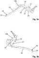
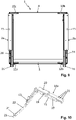
- the drawer frame 1 shown is attached to two pull-out runners 2a, 2b provided on both sides and has a front frame part 4 in the pull-out direction 3 of the pull-out runners 2a, 2b, a rear frame part 5 and two side frame parts 6a, 6b , which are connected to form a self-contained frame .
- the dash-dotted frame longitudinal central axis is denoted by 7 .
- the front and rear frame parts 4, 5 each have a (horizontal) floor leg 8 on which a floor plate (not shown) can be placed and fastened, and a (vertical) outer leg 9 adjoining the bottom leg 8 on the outside, which is aligned at right angles to the bottom leg 8 .
- the outer leg 9 has an upper leg section 9 1 extending above the base leg 8 and a lower leg section 9 2 extending below the base leg 8 .
- the bottom leg 8 can be bent in a Z-shape, as shown, in order to form a higher, horizontal, outer leg section 8 1 adjoining the outer leg 9 and a lower, horizontal, inner leg section 8 2 .
- the two side frame parts 6a, 6b can have the same profile cross-section as the front and rear frame parts 4, 5, so that in this case the drawer frame 1 has a circumferential, horizontal base leg 8 with two leg sections 8 1 , 8 2 and a circumferential , Vertical outer leg 9 with two leg sections 9 1 , 9 2 .
- Two front adapters 10a, 10b are guided on the front frame part 4 so as to be displaceable transversely to the longitudinal frame axis 7, which can be fastened along their transverse displacement direction 11 in one of several transverse positions which are spaced at different distances from the longitudinal central axis 7 of the frame.
- Two rear adapters 12a, 12b are guided on the rear frame part 5 so as to be displaceable transversely to the longitudinal frame axis 7, which can be fastened along their transverse displacement direction 11 in one of several transverse positions which are spaced at different distances from the longitudinal central axis 7 of the frame.
- the one in 1 left drawer guide 2a is attached to the left adapter pair, i.e.
- the right pull-out guide 2b is attached to the right pair of adapters, ie to the right, front and rear adapters 10b, 12b.
- the installation width B of the two pull-out guides 2a, 2b can be varied via the respective transverse position of the right and left adapter pairs 10a, 12a and 10b/12b.
- the adapters 10a, 10b and 12a, 12b thus make it possible to compensate for the protrusion dimension that arises with different side wall thicknesses of carcasses.
- the same drawer frame 1 can thus be used for different side wall thicknesses or for different installation widths B.
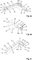
- the front adapters each have a front attachment interface 13 for attaching the pull-out guides 2a, 2b.
- the rear adapters each have a rear attachment interface 14 for attaching the pull-out guides 2a, 2b.
- the pull-out guides 2a, 2b each comprise a cabinet rail 15 for attachment to a cabinet side wall and a drawer rail 16, which is guided on the cabinet rail 15 or a central rail in the extension direction 3 and can be displaced, to which the drawer frame 1 is fixed.
- An intermediate element 17 is attached to the front attachment interface 13 , to which the front end of the drawer rail 16 is detachably attached by means of a locking element 18 .
- the front end of the drawer rail 16 can also be attached directly to the front attachment interface 13 without an intermediate element.
- the front attachment interface is preferably designed as a preferably vertical contact surface 13 with a plurality of holes 19 in order to be able to attach intermediate elements 18 with different hole patterns, for example from different manufacturers, to it.
- the front adapters 10a, 10b each have several holes arranged next to one another in the transverse displacement direction 11, namely a single adapter hole 20 and a group of several, here three, adapter holes 21.
- the front adapters 10a, 10b optionally each have a right-angled, arcuate, front spring arm 22 , the free arm end 23 of which is directed in the rearward direction.
- the front spring arm 22 extends on the inside in front of the lower leg section 9 2 of the respective lateral frame part 6a, 6b and is attached to the lateral frame part 6a, 6b.
- the free arm end 23 preferably has a pin 24 which is in a keyhole 25 ( Figs. 4a, 4c ) of the outer leg portion 8 1 of the side frame members 6a, 6b.
- the rear attachment interface is preferably designed as a recess 14 open to the rear, in order to be able to insert a forward-facing tab present at the rear end of the drawer rail 16 .
- the rear adapters 12a, 12b each have several adapter holes arranged next to one another in the transverse displacement direction 11, namely a group of three adapter holes 26 here.
- the rear adapters 12a, 12b each have a forward-pointing projection 27 which, in the installed state, extends through an opening in the floor leg 8 and thus prevents the rear adapter from being lifted off.
- the rear adapters 12a, 12b optionally each have a right-angled, arcuate, rear spring arm 28 , the free arm end 29 of which is directed in the forward direction.
- the rear spring arm 28 extends on the inside in front of the lower leg section 9 2 of the respective lateral frame part 6a, 6b and is attached to the lateral frame part 6a, 6b.
- the free arm end 29 preferably has a pin 30 which is fastened in a keyhole 31 of the outer leg section 81 of the lateral frame parts 6a, 6b.
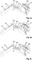
- the front adapters 10a, 10b can be slidably guided in the transverse direction 11 in a guide groove on the underside of the front frame part 4 , the groove base of which is formed by the outer leg section 81.
- the front adapter 10a is secured in the desired transverse position by means of two fasteners, here in the form of screws 32a, 32b .
- One screw 32a passes through a transverse frame slot 33 in the outer leg section 8 1 of the front frame part 4 and is screwed into the single adapter hole 20 of the front adapter 10a.
- the other screw 32b reaches through one of a plurality of frame holes 34 arranged equidistantly next to one another in the transverse displacement direction 11 in the outer leg section 8 1 and is screwed into one of the plurality of adapter holes 21 of the front adapter 10a.
- the adapter holes 21 in the front adapter 10a each have different distances.
- the rear adapters 12a, 12b are slidably guided in the transverse displacement direction 11 in a guide groove on the underside of the rear frame part 5 , the groove base of which is formed by the outer leg section 81.
- the rear adapter 12a, 12b is fastened in the desired transverse position by means of a fastening element, here in the form of a screw (not shown), which one of several frame holes (not shown) arranged equidistantly next to one another in the transverse displacement direction 11 in the outer leg section 8 1 of the rear frame part 5 passes through and is screwed into one of the plurality of adapter holes 26 of the rear adapter 12a, 12b.
- the adapter holes 26 in the rear adapter 12a, 12b each have different spacings.
- the transverse position of the pull-out guides 2a, 2b to the drawer frame 1, and thus the installation width B can be varied. Shifting the front and rear adapters in the transverse direction 11 results in a new combination of congruent frame and adapter holes, e.g. at a distance of 2 mm and 1 mm, into which the screws are screwed. This corresponds to side walls with a wall thickness of 16, 18 and 19 mm.
- the front and rear spring arms 22, 28 would be sufficiently elastic in the transverse displacement direction 11 to allow a transverse displacement of the adapter despite their fixed free arm end 23, 29.
- FIG. 5a-5c Figure 12 shows the left front adapter 10a in its three possible transverse positions, in each of which a different pair of adapter and frame holes 21, 34 are registered.
- the adapter 10a is located in Figure 5a in its outermost, in Figure 5b in its middle and in Figure 5c in its innermost transverse position.
- the assembly of the pull-out guides 2a, 2b and the two pairs of adapters 10a/12a and 10b/12b is as follows.
- the body rails 15 of the pull-out guides 2a, 2b are screwed to two side walls of the body.
- the intermediate elements 17 are screwed onto the flat contact surface 13 of the front adapters 10a, 10b.
- the two pairs of adapters 10a/12a and 10b/12b are adjusted by transverse displacement to the installation width B between the side walls of the body and are fastened in this transverse position to the front and rear frame parts 4, 5 by means of screws 32a, 32b.
- the drawer frame 1 is inserted between the two pull-out guides 2a, 2b in the opposite direction to the pull-out direction 3 until the rearward-pointing tabs located at the rear end of the drawer rails 16 are inserted into the recesses 14 of the rear adapters 12a, 12b and the front ends of the drawer rails 16 are locked to the intermediate elements 17 by means of the locking elements 18.
- the drawer frame 1 is now coupled for movement to the drawer rails 16 .
- the front and rear spring arms 22, 28 guided on the drawer rails 16 ensure that the drawer frame 1 is inserted without tilting.
- the adapters can alternatively also be guided transversely on a transverse surface or edge, or the adapters are placed in the desired transverse position without any guidance at all and fastened to the respective frame part 4, 5.
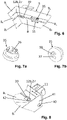
- FIG. 6 shows an alternative variant for transverse displacement and attachment of the adapter, here as an example using the example of the right rear adapter 12b, using an eccentric 35.
- the eccentric 35 is rotatably mounted in the outer leg portion 8 1 of the rear frame part 5 and has, as in the Figs. 7a, 7b shown, on the upper side, for example, a hexagon socket 36 and on the underside with respect to the eccentric axis of rotation eccentric, here spiral link guide 37 , into which a pin 38 of the rear adapter 12b engages.
- a rotation of the eccentric 35 thus causes a transverse movement of the rear adapter 12b in the transverse displacement direction 11.
- the projection 27 of the rear adapter 12b reaches through a vertical opening 39 in the bottom leg 8 and thus prevents the rear adapter 12b from lifting off the outer leg section 8 1 .
- FIG. 8 shows a further alternative variant for transverse displacement and attachment of the adapter, here using the example of the right-hand rear adapter 12b, by means of a lateral adjusting screw 40.
- the adjusting screw 40 can be rotated freely in an adapter side wall 41 , but is mounted so that it cannot be displaced axially and in a direction in the transverse displacement direction 11 extending thread of the rear frame part 5 screwed. A rotation of the adjusting screw 40 thus causes a transverse movement of the rear adapter 12b in the transverse displacement direction 11.
- the outer floor leg 8 2 can have several latching troughs or lugs 42 arranged next to one another in the transverse displacement direction 11, with which an underside latching lug or trough of the projection 27 is latched in each of the several transverse positions of the rear adapter.
- the outer base leg 82 can alternatively also have a plurality of markings 42 and the projection 27 can have a pointer (e.g. in the form of a point) which interacts with the markings 42 and which points to one of the markings in each of the several transverse positions of the rear adapter 42 is aligned to visually indicate the multiple transverse positions of the rear adapter.
- Drawer frame 1 From the drawer frame 1 differs in 9 Drawer frame 1 shown only in that the front adapters 10a, 10b do not have any intermediate and locking elements, but rather, as in 10 shown using the example of the left front adapter 10a, have a vertically aligned adapter hole 43 on the front spring arm 22.
- the drawer rails 16 have a vertical pin (not shown) at their front ends which engages in the adapter hole 43 to movably couple the drawer frame 1 to the drawer rail 16 .
- the drawer frame 1 which is raised at the front, is inserted between the two pull-out guides 2a, 2b in the opposite direction to the pull-out direction 3, until the rear-facing tabs located at the rear end of the drawer rails 16 are inserted into the recesses 14 of the rear adapters 12a, 12b. Then the drawer frame 1 is lowered, as a result of which the pins engage in the adapter holes 43.
- FIG. 11 shows the right frame side of the in 1 shown drawer frame 1 with an additional right protective element 44, which is on the right, front and rear adapters 10b, 12b, for example attached to their spring arms 22, 28, in particular latched.
- the protective element 44 can be designed as a U-shaped profile strip which encompasses the spring arms 22, 28 on three sides ( 12 ). Instead of being attached to the spring arms 22, 28, the protective element 44 can alternatively also be fastened, in particular latched, to non-resilient parts of the front and rear adapters 10b, 12b.
- a left-hand protective element is attached, in particular latched, to the left-hand, front and rear adapters 10a, 12a, for example to their spring arms 22, 28.
- the two protective elements 44 are moved transversely together with the adapters and ensure that the drawer frame 1 cannot rub and scratch the pull-out guides 2a, 2b throughout the assembly process.
- the two protective elements 44 can also be fixed in place on the drawer frame 1 .
Landscapes
- Drawers Of Furniture (AREA)
Applications Claiming Priority (1)
| Application Number | Priority Date | Filing Date | Title |
|---|---|---|---|
| DE202021103472.6U DE202021103472U1 (de) | 2021-06-29 | 2021-06-29 | Schubladenrahmen mit Adaptern für unterschiedliche Einbaubreiten |
Publications (3)
| Publication Number | Publication Date |
|---|---|
| EP4111908A1 true EP4111908A1 (fr) | 2023-01-04 |
| EP4111908C0 EP4111908C0 (fr) | 2024-02-14 |
| EP4111908B1 EP4111908B1 (fr) | 2024-02-14 |
Family
ID=76969057
Family Applications (1)
| Application Number | Title | Priority Date | Filing Date |
|---|---|---|---|
| EP22165081.5A Active EP4111908B1 (fr) | 2021-06-29 | 2022-03-29 | Cadre de tiroir pourvu d'adaptateurs pour différentes largeurs de pose |
Country Status (3)
| Country | Link |
|---|---|
| EP (1) | EP4111908B1 (fr) |
| CN (1) | CN115530557A (fr) |
| DE (1) | DE202021103472U1 (fr) |
Citations (1)
| Publication number | Priority date | Publication date | Assignee | Title |
|---|---|---|---|---|
| US20080169737A1 (en) * | 2007-01-16 | 2008-07-17 | Min-Dy Shen | Adjustable Pull-Out Frame Structure |
Family Cites Families (6)
| Publication number | Priority date | Publication date | Assignee | Title |
|---|---|---|---|---|
| GB1410377A (en) * | 1972-12-08 | 1975-10-15 | Lb Plastics Ltd | Drawers |
| US5044704A (en) * | 1990-05-17 | 1991-09-03 | Whirlpool Corporation | Adjustable refrigerator crisper drawer structure |
| DE4330919A1 (de) * | 1993-09-11 | 1995-03-16 | Lautenschlaeger Mepla Werke | Eck-Verbindungsbeschlag für Schubladen |
| CN1709183A (zh) * | 2004-06-17 | 2005-12-21 | 欧仕达家具制造商 | 带有可变定位的面板的抽屉 |
| AT508265B1 (de) * | 2009-06-10 | 2013-05-15 | Blum Gmbh Julius | Ausziehführung für schubladen |
| DE102015105131B4 (de) * | 2015-04-02 | 2024-06-20 | Paul Hettich Gmbh & Co. Kg | Zarge, insbesondere Seitenzarge, für einen Schubkasten |
-
2021
- 2021-06-29 DE DE202021103472.6U patent/DE202021103472U1/de active Active
-
2022
- 2022-03-29 EP EP22165081.5A patent/EP4111908B1/fr active Active
- 2022-05-10 CN CN202210505092.3A patent/CN115530557A/zh active Pending
Patent Citations (1)
| Publication number | Priority date | Publication date | Assignee | Title |
|---|---|---|---|---|
| US20080169737A1 (en) * | 2007-01-16 | 2008-07-17 | Min-Dy Shen | Adjustable Pull-Out Frame Structure |
Also Published As
| Publication number | Publication date |
|---|---|
| EP4111908C0 (fr) | 2024-02-14 |
| CN115530557A (zh) | 2022-12-30 |
| EP4111908B1 (fr) | 2024-02-14 |
| DE202021103472U1 (de) | 2021-07-07 |
Similar Documents
| Publication | Publication Date | Title |
|---|---|---|
| EP0421458B1 (fr) | Tiroir | |
| EP0545329B1 (fr) | Accessoire pour glissière de tiroir | |
| DE3532419C2 (fr) | ||
| EP2994011A1 (fr) | Guidage télescopique | |
| EP0041616B1 (fr) | Glissière télescopique pour support, tel que tiroirou similaire | |
| EP3746627B1 (fr) | Équerre de fixation pour le montage des rails supérieurs des stores vénitiens | |
| DE2941126A1 (de) | Zum schutz eines maschinenbettes bestimmte abdeckung | |
| EP2354732B1 (fr) | Porte d'un appareil de réfrigération et/ou de congélation | |
| DE3439694C2 (fr) | ||
| EP2148592A1 (fr) | Dispositif de couplage pour partie de meuble mobile | |
| DE3149310A1 (de) | Vorrichtung und verfahren zur befestigung von elektrischen installationsgeraeten auf normprofilschienen, insbesondere auf hutprofilschienen | |
| EP0761132A1 (fr) | Dispositif de réglage pour aligner des glissières supportant un tiroir, une rallonge ou similaire | |
| EP4111908B1 (fr) | Cadre de tiroir pourvu d'adaptateurs pour différentes largeurs de pose | |
| DE69503828T2 (de) | Blokiervorrichtung für eine Verlängerung Bezüglich eines Möbelstückes, und Möbelstück damit Ausgestattet | |
| EP3923767B1 (fr) | Tiroir | |
| DE102018101342A1 (de) | Ausziehführung für einen Schubkasten und Verfahren zum Ausrichten eines Schubkastens an einer Ausziehführung | |
| DE20008266U1 (de) | Ausziehsperre für und Möbel mit einer solchen übereinander angeordnete Schubladen | |
| DE69510627T2 (de) | Geräteträgereinrichtung Einzubringen auf einen Kabelkanalkörper | |
| AT400660B (de) | Ausziehführungsgarnitur für eine schublade | |
| DE3409732C2 (de) | Einbau-Aschenbecher für Kraftfahrzeuge | |
| DE7535313U (de) | Schubkasten-fuehrungsschiene | |
| EP0639687A1 (fr) | Glissière | |
| EP4129116B1 (fr) | Guide pourvu d'adaptateur avant permettant de verrouiller un élément tiroir | |
| DE29917503U1 (de) | Vorrichtung | |
| DE2708427A1 (de) | Vorrichtung zum verbinden von moebelstuecken, insbesondere der fuesse von polsterelementen |
Legal Events
| Date | Code | Title | Description |
|---|---|---|---|
| PUAI | Public reference made under article 153(3) epc to a published international application that has entered the european phase |
Free format text: ORIGINAL CODE: 0009012 |
|
| STAA | Information on the status of an ep patent application or granted ep patent |
Free format text: STATUS: REQUEST FOR EXAMINATION WAS MADE |
|
| 17P | Request for examination filed |
Effective date: 20220930 |
|
| AK | Designated contracting states |
Kind code of ref document: A1 Designated state(s): AL AT BE BG CH CY CZ DE DK EE ES FI FR GB GR HR HU IE IS IT LI LT LU LV MC MK MT NL NO PL PT RO RS SE SI SK SM TR |
|
| GRAP | Despatch of communication of intention to grant a patent |
Free format text: ORIGINAL CODE: EPIDOSNIGR1 |
|
| STAA | Information on the status of an ep patent application or granted ep patent |
Free format text: STATUS: GRANT OF PATENT IS INTENDED |
|
| INTG | Intention to grant announced |
Effective date: 20230531 |
|
| P01 | Opt-out of the competence of the unified patent court (upc) registered |
Effective date: 20230630 |
|
| GRAJ | Information related to disapproval of communication of intention to grant by the applicant or resumption of examination proceedings by the epo deleted |
Free format text: ORIGINAL CODE: EPIDOSDIGR1 |
|
| STAA | Information on the status of an ep patent application or granted ep patent |
Free format text: STATUS: REQUEST FOR EXAMINATION WAS MADE |
|
| INTC | Intention to grant announced (deleted) | ||
| GRAP | Despatch of communication of intention to grant a patent |
Free format text: ORIGINAL CODE: EPIDOSNIGR1 |
|
| STAA | Information on the status of an ep patent application or granted ep patent |
Free format text: STATUS: GRANT OF PATENT IS INTENDED |
|
| INTG | Intention to grant announced |
Effective date: 20230915 |
|
| GRAS | Grant fee paid |
Free format text: ORIGINAL CODE: EPIDOSNIGR3 |
|
| GRAA | (expected) grant |
Free format text: ORIGINAL CODE: 0009210 |
|
| STAA | Information on the status of an ep patent application or granted ep patent |
Free format text: STATUS: THE PATENT HAS BEEN GRANTED |
|
| AK | Designated contracting states |
Kind code of ref document: B1 Designated state(s): AL AT BE BG CH CY CZ DE DK EE ES FI FR GB GR HR HU IE IS IT LI LT LU LV MC MK MT NL NO PL PT RO RS SE SI SK SM TR |
|
| REG | Reference to a national code |
Ref country code: GB Ref legal event code: FG4D Free format text: NOT ENGLISH |
|
| REG | Reference to a national code |
Ref country code: CH Ref legal event code: EP |
|
| REG | Reference to a national code |
Ref country code: DE Ref legal event code: R096 Ref document number: 502022000490 Country of ref document: DE |
|
| REG | Reference to a national code |
Ref country code: IE Ref legal event code: FG4D Free format text: LANGUAGE OF EP DOCUMENT: GERMAN |
|
| U01 | Request for unitary effect filed |
Effective date: 20240228 |
|
| U07 | Unitary effect registered |
Designated state(s): AT BE BG DE DK EE FI FR IT LT LU LV MT NL PT SE SI Effective date: 20240304 |
|
| U20 | Renewal fee for the european patent with unitary effect paid |
Year of fee payment: 3 Effective date: 20240326 |
|
| P04 | Withdrawal of opt-out of the competence of the unified patent court (upc) registered |
Effective date: 20240412 |
|
| REG | Reference to a national code |
Ref country code: LT Ref legal event code: MG9D |
|
| PG25 | Lapsed in a contracting state [announced via postgrant information from national office to epo] |
Ref country code: IS Free format text: LAPSE BECAUSE OF FAILURE TO SUBMIT A TRANSLATION OF THE DESCRIPTION OR TO PAY THE FEE WITHIN THE PRESCRIBED TIME-LIMIT Effective date: 20240614 |
|
| PG25 | Lapsed in a contracting state [announced via postgrant information from national office to epo] |
Ref country code: GR Free format text: LAPSE BECAUSE OF FAILURE TO SUBMIT A TRANSLATION OF THE DESCRIPTION OR TO PAY THE FEE WITHIN THE PRESCRIBED TIME-LIMIT Effective date: 20240515 |
|
| PG25 | Lapsed in a contracting state [announced via postgrant information from national office to epo] |
Ref country code: RS Free format text: LAPSE BECAUSE OF FAILURE TO SUBMIT A TRANSLATION OF THE DESCRIPTION OR TO PAY THE FEE WITHIN THE PRESCRIBED TIME-LIMIT Effective date: 20240514 Ref country code: HR Free format text: LAPSE BECAUSE OF FAILURE TO SUBMIT A TRANSLATION OF THE DESCRIPTION OR TO PAY THE FEE WITHIN THE PRESCRIBED TIME-LIMIT Effective date: 20240214 |
|
| PG25 | Lapsed in a contracting state [announced via postgrant information from national office to epo] |
Ref country code: ES Free format text: LAPSE BECAUSE OF FAILURE TO SUBMIT A TRANSLATION OF THE DESCRIPTION OR TO PAY THE FEE WITHIN THE PRESCRIBED TIME-LIMIT Effective date: 20240214 |
|
| PG25 | Lapsed in a contracting state [announced via postgrant information from national office to epo] |
Ref country code: RS Free format text: LAPSE BECAUSE OF FAILURE TO SUBMIT A TRANSLATION OF THE DESCRIPTION OR TO PAY THE FEE WITHIN THE PRESCRIBED TIME-LIMIT Effective date: 20240514 Ref country code: NO Free format text: LAPSE BECAUSE OF FAILURE TO SUBMIT A TRANSLATION OF THE DESCRIPTION OR TO PAY THE FEE WITHIN THE PRESCRIBED TIME-LIMIT Effective date: 20240514 Ref country code: IS Free format text: LAPSE BECAUSE OF FAILURE TO SUBMIT A TRANSLATION OF THE DESCRIPTION OR TO PAY THE FEE WITHIN THE PRESCRIBED TIME-LIMIT Effective date: 20240614 Ref country code: HR Free format text: LAPSE BECAUSE OF FAILURE TO SUBMIT A TRANSLATION OF THE DESCRIPTION OR TO PAY THE FEE WITHIN THE PRESCRIBED TIME-LIMIT Effective date: 20240214 Ref country code: GR Free format text: LAPSE BECAUSE OF FAILURE TO SUBMIT A TRANSLATION OF THE DESCRIPTION OR TO PAY THE FEE WITHIN THE PRESCRIBED TIME-LIMIT Effective date: 20240515 Ref country code: ES Free format text: LAPSE BECAUSE OF FAILURE TO SUBMIT A TRANSLATION OF THE DESCRIPTION OR TO PAY THE FEE WITHIN THE PRESCRIBED TIME-LIMIT Effective date: 20240214 |
|
| PG25 | Lapsed in a contracting state [announced via postgrant information from national office to epo] |
Ref country code: PL Free format text: LAPSE BECAUSE OF FAILURE TO SUBMIT A TRANSLATION OF THE DESCRIPTION OR TO PAY THE FEE WITHIN THE PRESCRIBED TIME-LIMIT Effective date: 20240214 |
|
| PG25 | Lapsed in a contracting state [announced via postgrant information from national office to epo] |
Ref country code: PL Free format text: LAPSE BECAUSE OF FAILURE TO SUBMIT A TRANSLATION OF THE DESCRIPTION OR TO PAY THE FEE WITHIN THE PRESCRIBED TIME-LIMIT Effective date: 20240214 |
|
| PG25 | Lapsed in a contracting state [announced via postgrant information from national office to epo] |
Ref country code: SM Free format text: LAPSE BECAUSE OF FAILURE TO SUBMIT A TRANSLATION OF THE DESCRIPTION OR TO PAY THE FEE WITHIN THE PRESCRIBED TIME-LIMIT Effective date: 20240214 |
|
| PG25 | Lapsed in a contracting state [announced via postgrant information from national office to epo] |
Ref country code: CZ Free format text: LAPSE BECAUSE OF FAILURE TO SUBMIT A TRANSLATION OF THE DESCRIPTION OR TO PAY THE FEE WITHIN THE PRESCRIBED TIME-LIMIT Effective date: 20240214 |
|
| PG25 | Lapsed in a contracting state [announced via postgrant information from national office to epo] |
Ref country code: SK Free format text: LAPSE BECAUSE OF FAILURE TO SUBMIT A TRANSLATION OF THE DESCRIPTION OR TO PAY THE FEE WITHIN THE PRESCRIBED TIME-LIMIT Effective date: 20240214 |
|
| PG25 | Lapsed in a contracting state [announced via postgrant information from national office to epo] |
Ref country code: SM Free format text: LAPSE BECAUSE OF FAILURE TO SUBMIT A TRANSLATION OF THE DESCRIPTION OR TO PAY THE FEE WITHIN THE PRESCRIBED TIME-LIMIT Effective date: 20240214 Ref country code: SK Free format text: LAPSE BECAUSE OF FAILURE TO SUBMIT A TRANSLATION OF THE DESCRIPTION OR TO PAY THE FEE WITHIN THE PRESCRIBED TIME-LIMIT Effective date: 20240214 Ref country code: RO Free format text: LAPSE BECAUSE OF FAILURE TO SUBMIT A TRANSLATION OF THE DESCRIPTION OR TO PAY THE FEE WITHIN THE PRESCRIBED TIME-LIMIT Effective date: 20240214 Ref country code: CZ Free format text: LAPSE BECAUSE OF FAILURE TO SUBMIT A TRANSLATION OF THE DESCRIPTION OR TO PAY THE FEE WITHIN THE PRESCRIBED TIME-LIMIT Effective date: 20240214 |
|
| REG | Reference to a national code |
Ref country code: DE Ref legal event code: R097 Ref document number: 502022000490 Country of ref document: DE |
|
| PG25 | Lapsed in a contracting state [announced via postgrant information from national office to epo] |
Ref country code: MC Free format text: LAPSE BECAUSE OF FAILURE TO SUBMIT A TRANSLATION OF THE DESCRIPTION OR TO PAY THE FEE WITHIN THE PRESCRIBED TIME-LIMIT Effective date: 20240214 |
|
| PG25 | Lapsed in a contracting state [announced via postgrant information from national office to epo] |
Ref country code: MC Free format text: LAPSE BECAUSE OF FAILURE TO SUBMIT A TRANSLATION OF THE DESCRIPTION OR TO PAY THE FEE WITHIN THE PRESCRIBED TIME-LIMIT Effective date: 20240214 |
|
| PLBE | No opposition filed within time limit |
Free format text: ORIGINAL CODE: 0009261 |
|
| STAA | Information on the status of an ep patent application or granted ep patent |
Free format text: STATUS: NO OPPOSITION FILED WITHIN TIME LIMIT |
|
| 26N | No opposition filed |
Effective date: 20241115 |
|
| PG25 | Lapsed in a contracting state [announced via postgrant information from national office to epo] |
Ref country code: IE Free format text: LAPSE BECAUSE OF NON-PAYMENT OF DUE FEES Effective date: 20240329 |
|
| PG25 | Lapsed in a contracting state [announced via postgrant information from national office to epo] |
Ref country code: IE Free format text: LAPSE BECAUSE OF NON-PAYMENT OF DUE FEES Effective date: 20240329 |
|
| U20 | Renewal fee for the european patent with unitary effect paid |
Year of fee payment: 4 Effective date: 20250324 |
|
| PG25 | Lapsed in a contracting state [announced via postgrant information from national office to epo] |
Ref country code: CY Free format text: LAPSE BECAUSE OF FAILURE TO SUBMIT A TRANSLATION OF THE DESCRIPTION OR TO PAY THE FEE WITHIN THE PRESCRIBED TIME-LIMIT; INVALID AB INITIO Effective date: 20220329 |
|
| REG | Reference to a national code |
Ref country code: CH Ref legal event code: H13 Free format text: ST27 STATUS EVENT CODE: U-0-0-H10-H13 (AS PROVIDED BY THE NATIONAL OFFICE) Effective date: 20251024 |