EP4108932A1 - Reciate et pompe à vide élevé - Google Patents
Reciate et pompe à vide élevé Download PDFInfo
- Publication number
- EP4108932A1 EP4108932A1 EP22198845.4A EP22198845A EP4108932A1 EP 4108932 A1 EP4108932 A1 EP 4108932A1 EP 22198845 A EP22198845 A EP 22198845A EP 4108932 A1 EP4108932 A1 EP 4108932A1
- Authority
- EP
- European Patent Office
- Prior art keywords
- pump
- vacuum
- fore
- connection
- recipient
- Prior art date
- Legal status (The legal status is an assumption and is not a legal conclusion. Google has not performed a legal analysis and makes no representation as to the accuracy of the status listed.)
- Pending
Links
- 238000005086 pumping Methods 0.000 claims description 14
- 230000000295 complement effect Effects 0.000 claims description 8
- 238000001816 cooling Methods 0.000 claims description 8
- 239000007789 gas Substances 0.000 description 18
- 239000002826 coolant Substances 0.000 description 9
- 238000007789 sealing Methods 0.000 description 6
- 239000007921 spray Substances 0.000 description 5
- 239000012530 fluid Substances 0.000 description 4
- 238000002347 injection Methods 0.000 description 4
- 239000007924 injection Substances 0.000 description 4
- 238000000034 method Methods 0.000 description 4
- 230000008569 process Effects 0.000 description 4
- 238000005520 cutting process Methods 0.000 description 3
- 238000011010 flushing procedure Methods 0.000 description 3
- 238000012423 maintenance Methods 0.000 description 3
- 238000004519 manufacturing process Methods 0.000 description 3
- IJGRMHOSHXDMSA-UHFFFAOYSA-N Atomic nitrogen Chemical compound N#N IJGRMHOSHXDMSA-UHFFFAOYSA-N 0.000 description 2
- 238000010276 construction Methods 0.000 description 2
- 230000017525 heat dissipation Effects 0.000 description 2
- 125000006850 spacer group Chemical group 0.000 description 2
- 230000002745 absorbent Effects 0.000 description 1
- 239000002250 absorbent Substances 0.000 description 1
- 230000009471 action Effects 0.000 description 1
- 230000008901 benefit Effects 0.000 description 1
- 230000005540 biological transmission Effects 0.000 description 1
- 230000008859 change Effects 0.000 description 1
- 230000000694 effects Effects 0.000 description 1
- 238000009434 installation Methods 0.000 description 1
- 239000000314 lubricant Substances 0.000 description 1
- 230000001050 lubricating effect Effects 0.000 description 1
- 229910052757 nitrogen Inorganic materials 0.000 description 1
- 238000005457 optimization Methods 0.000 description 1
- 238000010008 shearing Methods 0.000 description 1
- 239000000243 solution Substances 0.000 description 1
Images


Classifications
-
- F—MECHANICAL ENGINEERING; LIGHTING; HEATING; WEAPONS; BLASTING
- F04—POSITIVE - DISPLACEMENT MACHINES FOR LIQUIDS; PUMPS FOR LIQUIDS OR ELASTIC FLUIDS
- F04D—NON-POSITIVE-DISPLACEMENT PUMPS
- F04D19/00—Axial-flow pumps
- F04D19/02—Multi-stage pumps
- F04D19/04—Multi-stage pumps specially adapted to the production of a high vacuum, e.g. molecular pumps
- F04D19/046—Combinations of two or more different types of pumps
-
- F—MECHANICAL ENGINEERING; LIGHTING; HEATING; WEAPONS; BLASTING
- F04—POSITIVE - DISPLACEMENT MACHINES FOR LIQUIDS; PUMPS FOR LIQUIDS OR ELASTIC FLUIDS
- F04D—NON-POSITIVE-DISPLACEMENT PUMPS
- F04D25/00—Pumping installations or systems
- F04D25/16—Combinations of two or more pumps ; Producing two or more separate gas flows
-
- F—MECHANICAL ENGINEERING; LIGHTING; HEATING; WEAPONS; BLASTING
- F04—POSITIVE - DISPLACEMENT MACHINES FOR LIQUIDS; PUMPS FOR LIQUIDS OR ELASTIC FLUIDS
- F04D—NON-POSITIVE-DISPLACEMENT PUMPS
- F04D29/00—Details, component parts, or accessories
- F04D29/40—Casings; Connections of working fluid
- F04D29/52—Casings; Connections of working fluid for axial pumps
- F04D29/522—Casings; Connections of working fluid for axial pumps especially adapted for elastic fluid pumps
-
- F—MECHANICAL ENGINEERING; LIGHTING; HEATING; WEAPONS; BLASTING
- F04—POSITIVE - DISPLACEMENT MACHINES FOR LIQUIDS; PUMPS FOR LIQUIDS OR ELASTIC FLUIDS
- F04D—NON-POSITIVE-DISPLACEMENT PUMPS
- F04D29/00—Details, component parts, or accessories
- F04D29/60—Mounting; Assembling; Disassembling
- F04D29/601—Mounting; Assembling; Disassembling specially adapted for elastic fluid pumps
- F04D29/602—Mounting in cavities
-
- F—MECHANICAL ENGINEERING; LIGHTING; HEATING; WEAPONS; BLASTING
- F04—POSITIVE - DISPLACEMENT MACHINES FOR LIQUIDS; PUMPS FOR LIQUIDS OR ELASTIC FLUIDS
- F04D—NON-POSITIVE-DISPLACEMENT PUMPS
- F04D29/00—Details, component parts, or accessories
- F04D29/60—Mounting; Assembling; Disassembling
- F04D29/64—Mounting; Assembling; Disassembling of axial pumps
- F04D29/644—Mounting; Assembling; Disassembling of axial pumps especially adapted for elastic fluid pumps
-
- F—MECHANICAL ENGINEERING; LIGHTING; HEATING; WEAPONS; BLASTING
- F04—POSITIVE - DISPLACEMENT MACHINES FOR LIQUIDS; PUMPS FOR LIQUIDS OR ELASTIC FLUIDS
- F04D—NON-POSITIVE-DISPLACEMENT PUMPS
- F04D19/00—Axial-flow pumps
- F04D19/02—Multi-stage pumps
- F04D19/04—Multi-stage pumps specially adapted to the production of a high vacuum, e.g. molecular pumps
- F04D19/042—Turbomolecular vacuum pumps
-
- F—MECHANICAL ENGINEERING; LIGHTING; HEATING; WEAPONS; BLASTING
- F04—POSITIVE - DISPLACEMENT MACHINES FOR LIQUIDS; PUMPS FOR LIQUIDS OR ELASTIC FLUIDS
- F04D—NON-POSITIVE-DISPLACEMENT PUMPS
- F04D19/00—Axial-flow pumps
- F04D19/02—Multi-stage pumps
- F04D19/04—Multi-stage pumps specially adapted to the production of a high vacuum, e.g. molecular pumps
- F04D19/044—Holweck-type pumps
-
- F—MECHANICAL ENGINEERING; LIGHTING; HEATING; WEAPONS; BLASTING
- F05—INDEXING SCHEMES RELATING TO ENGINES OR PUMPS IN VARIOUS SUBCLASSES OF CLASSES F01-F04
- F05D—INDEXING SCHEME FOR ASPECTS RELATING TO NON-POSITIVE-DISPLACEMENT MACHINES OR ENGINES, GAS-TURBINES OR JET-PROPULSION PLANTS
- F05D2250/00—Geometry
- F05D2250/50—Inlet or outlet
- F05D2250/52—Outlet
Definitions
- the invention relates to a recipient and a high-vacuum pump.
- High vacuum pumps in particular turbomolecular pumps, are used to generate a high vacuum in one or more vacuum chambers of a recipient.
- an inlet side of the vacuum pump is connected to the one or more vacuum chambers of the recipient.
- an inlet flange of the vacuum pump is conventionally connected to a flange of the recipient.
- the pump housing can be formed by the recipient, i.e. the active pumping parts of the high-vacuum pump could be integrated into the recipient and form a pump unit together with it.
- a pre-vacuum in order to generate a high vacuum on an output side of the corresponding high-vacuum pump, a pre-vacuum must generally first be generated so that the high-vacuum pump is able to reach the desired final speed. This is usually done using a fore-vacuum pump, which must be connected to the high-vacuum pump via a corresponding fore-vacuum connection.
- the realization of such arrangements can be complex and take up a lot of space, especially when customer-specific requirements have to be met.
- the flanges to be connected may have different diameters and therefore cannot be mounted directly on top of each other, or the flanges may be unfavorable for mounting on both sides Positions are located while the customer wants a compact design. Fulfilling these and similar requirements requires the development of customer-specific individual solutions, which can be time-consuming and expensive.
- one object of the present invention is to provide a recipient and a high-vacuum pump which can be used flexibly.
- a recipient comprising at least one pump housing and at least one vacuum chamber, which comprises a pump connection for establishing a connection to an inlet side of a high-vacuum pump, in particular a turbomolecular pump.
- the recipient according to the invention has a fore-vacuum connection section which is firmly connected to the vacuum chamber and comprises a fore-vacuum connection for establishing a connection to an inlet side of a fore-vacuum pump.
- a recipient comprising at least one pump receiving section for receiving the high-vacuum pump in the recipient, and at least one vacuum chamber which includes a pump connection for establishing a connection to an inlet side of a high-vacuum pump, in particular a turbomolecular pump.
- the recipient has a fore-vacuum connection section, which is firmly connected to the vacuum chamber and comprises a fore-vacuum connection for establishing a connection to an inlet side of a fore-vacuum pump.
- the fore-vacuum connection is part of the customer application.
- the fore-vacuum connection section can include a fore-vacuum chamber, i.e. the fore-vacuum chamber can also be part of the customer application, which considerably simplifies the connection of a fore-vacuum pump to generate the fore-vacuum.
- the vacuum chamber and the fore-vacuum connection section can also have a common housing.
- a housing of the vacuum chamber and/or of the fore-vacuum connection section can form the pump receiving section.
- the housing can form at least one section of a pump housing of the high-vacuum pump, which makes it possible to integrate the high-vacuum pump in the recipient in a particularly space-saving manner.
- Vacuum chamber housing and vacuum pump preferably form a pump unit in which the pump and chamber have the same housing. An additional pump housing would no longer be necessary in this form.
- the pump receiving section surrounds the high-vacuum pump at least in sections.
- the pump receiving portion can be detachably connected to the housing and / or Be connected to the vacuum chamber and / or the fore-vacuum connection section.
- Such a configuration of the pump receiving section offers a high degree of flexibility with regard to the mounting position and the type of mounting of the high-vacuum pump.
- a closing element can be provided which at least partially covers the high-vacuum pump in an assembled state in the axial direction and which comprises at least one channel for establishing a connection between an output side of the high-vacuum pump and the fore-vacuum connection section.
- a closing element considerably simplifies the production of the connection between the fore-vacuum chamber and the fore-vacuum pump by the customer and can at the same time ensure that the high-vacuum pump is secured and/or fixed (proper, secure fastening).
- the closing element can be or comprise a component which is separate from the high-vacuum pump and which can be detachably fastened to the high-vacuum pump and/or to the vacuum chamber and/or to the fore-vacuum connection section and/or to the pump receiving section.
- the closing element forms a type of cover that covers the high-vacuum pump and/or secures it on or in the pump receiving section.
- the closing element can be designed as a fastening cover.
- the high-vacuum pump can be attached to the recipient with this attachment cover.
- the high-vacuum pump can be mounted on the closing element.
- a further advantage is, for example, that the radius of a circle of holes for fastening screws of the cover can be increased, as a result of which the risk of screws shearing off in the event of a crash can be reduced.
- the closing element can be an additional cooling element or act as such an element.
- the closing element preferably dissipates the heat generated during operation through contact with the base section of the high-vacuum pump.
- the closing element can have a first feature that can be brought into engagement with a second feature that is complementary to the first feature and that is on the high-vacuum pump and/or on the vacuum chamber and/or on the fore-vacuum connection section and/or the pump receiving section is formed.
- the complementary shape features can also form a code that ensures that the terminating element can only be fastened in the correct manner.
- the shape features allow the vacuum pump to be assembled and disassembled by the recipient in a well-defined direction.
- the channel of the closure element has a first outlet connection which can be connected to the fore-vacuum connection section.
- the channel of the closing element can have a second outlet connection which can be connected to a fore-vacuum pump.
- This can enable efficient gas routing during operation of the high-vacuum pump.
- this enables constructive possibilities and increased flexibility in the construction of the recipient-vacuum pump structure with regard to the spatial positioning of the fore-vacuum flange.
- a fore-vacuum chamber of the recipient can thus be connected to the fore-vacuum pump via the closing element.
- the terminating element can be provided with heat exchange elements, in which case the heat exchange elements can in particular be cooling fins.
- Protection is also sought for a system comprising a recipient according to at least one of the embodiments described above and a high-vacuum pump connected or connectable thereto. This applies in particular to embodiments in which the closing element can be or is a component part of the pump.
- a vacuum pump in particular a turbomolecular pump, which can be mounted in particular on or in a pump receiving section of a recipient according to the invention and which comprises a stator and a rotor which can be driven by a motor to rotate about an axis of rotation and which in a pump housing are arranged, with a closure element being provided which closes off the vacuum pump at its end downstream in the pumping direction in the axial direction, with the closure element having at least two, in particular a plurality of pump outlet openings distributed around the axis of rotation, the outlet openings of which are on an outlet-side end face of the vacuum pump are arranged.
- the pump outlet openings are openings which extend in the axial direction and which therefore cause the pumped medium to be discharged in the axial direction from the pump.
- the pump outlet openings have a straight course, ie they are free of steps, bends, kinks or the like in order to minimize the flow resistance on the outlet side.
- the pump outlet openings thus enable efficient gas routing at the downstream end of the vacuum pump, and hence improved pumping performance.
- the closing element and at least one housing component form the pump housing.
- an axial extent of the closing element in the area of its outer circumference can be more than 20%, in particular more than 30% or more than 38%, of an axial extent of the housing component.
- the closing element can form a not insignificant part of the vacuum pump.
- an outside diameter of the closing element and an outside diameter of the housing component can be approximately the same size at least in a region in which the closing element and the housing component are connected to one another.
- the closing element has a receiving section that extends from a bottom section of the closing element that forms the downstream end of a pump chamber of the vacuum pump in the direction of the housing component, with the receiving section covering at least part of the motor and/or one of the Rotor superimposed bearing portion receives.
- Protection is also sought for a system comprising a high-vacuum pump according to at least one of the embodiments described above and a recipient connected or connectable thereto, which is designed in particular according to one of the embodiments described further above.
- the turbomolecular pump 111 shown comprises a pump inlet 115 surrounded by an inlet flange 113, to which a recipient, not shown, can be connected in a manner known per se.
- the gas from the recipient can be sucked out of the recipient via the pump inlet 115 and conveyed through the pump to a pump outlet 117 to which a backing pump, such as a rotary vane pump, can be connected.
- the inlet flange 113 forms when the vacuum pump is aligned according to FIG 1 the upper end of the housing 119 of the vacuum pump 111.
- the housing 119 comprises a lower part 121 on which an electronics housing 123 is arranged laterally. Electrical and/or electronic components of the vacuum pump 111 are accommodated in the electronics housing 123, for example for operating an electric motor 125 arranged in the vacuum pump (cf. also 3 ). Several connections 127 for accessories are provided on the electronics housing 123 .
- a data interface 129 for example according to the RS485 standard, and a power supply connection 131 are arranged on the electronics housing 123.
- turbomolecular pumps that do not have such an attached electronics housing, but are connected to external drive electronics.
- a flood inlet 133 in particular in the form of a flood valve, is provided on the housing 119 of the turbomolecular pump 111, via which the vacuum pump 111 can be flooded.
- a sealing gas connection 135, which is also referred to as a flushing gas connection through which flushing gas to protect the electric motor 125 (see e.g 3 ) before the pumped gas in the motor compartment 137, in which the electric motor 125 is housed in the vacuum pump 111, can be admitted.
- Two coolant connections 139 are also arranged in the lower part 121, one of the coolant connections being provided as an inlet and the other coolant connection being provided as an outlet for coolant, which can be conducted into the vacuum pump for cooling purposes.
- Other existing turbomolecular vacuum pumps (not shown) operate solely on air cooling.
- the lower side 141 of the vacuum pump can serve as a standing surface, so that the vacuum pump 111 can be operated standing on the underside 141 .
- the vacuum pump 111 can also be fastened to a recipient via the inlet flange 113 and can thus be operated in a suspended manner, as it were.
- the vacuum pump 111 can be designed in such a way that it can also be operated when it is oriented in a different way than in FIG 1 is shown. It is also possible to realize embodiments of the vacuum pump in which the underside 141 cannot be arranged facing downwards but to the side or directed upwards. In principle, any angles are possible.
- various screws 143 are also arranged, by means of which components of the vacuum pump that are not further specified here are fastened to one another.
- a bearing cap 145 is attached to the underside 141 .
- fastening bores 147 are arranged on the underside 141, via which the pump 111 can be fastened, for example, to a support surface. This is not possible with other existing turbomolecular vacuum pumps (not shown), which in particular are larger than the pump shown here.
- a coolant line 148 is shown, in which the coolant fed in and out via the coolant connections 139 can circulate.
- the vacuum pump comprises several process gas pump stages for conveying the process gas present at the pump inlet 115 to the pump outlet 117.
- a rotor 149 is arranged in the housing 119 and has a rotor shaft 153 which can be rotated about an axis of rotation 151 .
- the turbomolecular pump 111 comprises a plurality of turbomolecular pumping stages connected in series with one another in a pumping manner, with a plurality of radial rotor disks 155 fastened to the rotor shaft 153 and stator disks 157 arranged between the rotor disks 155 and fixed in the housing 119.
- a rotor disk 155 and an adjacent stator disk 157 each form a turbomolecular pump stage.
- the stator discs 157 are held at a desired axial distance from one another by spacer rings 159 .
- the vacuum pump also comprises Holweck pump stages which are arranged one inside the other in the radial direction and are connected in series with one another for pumping purposes.
- Other turbomolecular vacuum pumps (not shown) exist that do not have Holweck pumping stages.
- the rotor of the Holweck pump stages comprises a rotor hub 161 arranged on the rotor shaft 153 and two Holweck rotor sleeves 163, 165 in the shape of a cylinder jacket, fastened to the rotor hub 161 and carried by it, which are oriented coaxially to the axis of rotation 151 and are nested in one another in the radial direction. Also provided are two cylinder jacket-shaped Holweck stator sleeves 167, 169, which are also oriented coaxially with respect to the axis of rotation 151 and are nested in one another when viewed in the radial direction.
- the pumping-active surfaces of the Holweck pump stages are through the lateral surfaces, ie through the radial inner and/or outer surfaces, of the Holweck rotor sleeves 163, 165 and the Holweck stator sleeves 167, 169 are formed.
- the radial inner surface of the outer Holweck stator sleeve 167 lies opposite the radial outer surface of the outer Holweck rotor sleeve 163, forming a radial Holweck gap 171 and forming with it the first Holweck pump stage following the turbomolecular pumps.
- the radially inner surface of the outer Holweck rotor sleeve 163 faces the radially outer surface of the inner Holweck stator sleeve 169 to form a radial Holweck gap 173 and therewith forms a second Holweck pumping stage.
- the radially inner surface of the inner Holweck stator sleeve 169 faces the radially outer surface of the inner Holweck rotor sleeve 165 to form a radial Holweck gap 175 and therewith forms the third Holweck pumping stage.
- a radially running channel can be provided, via which the radially outer Holweck gap 171 is connected to the middle Holweck gap 173.
- a radially extending channel can be provided at the upper end of the inner Holweck stator sleeve 169, via which the middle Holweck gap 173 is connected to the radially inner Holweck gap 175.
- a connecting channel 179 to the outlet 117 can be provided at the lower end of the radially inner Holweck rotor sleeve 165 .
- the above-mentioned pumping-active surfaces of the Holweck stator sleeves 167, 169 each have a plurality of Holweck grooves running in a spiral shape around the axis of rotation 151 in the axial direction, while the opposite lateral surfaces of the Holweck rotor sleeves 163, 165 are smooth and the gas for operating the Advance vacuum pump 111 in the Holweck grooves.
- a roller bearing 181 in the region of the pump outlet 117 and a permanent magnet bearing 183 in the region of the pump inlet 115 are provided for the rotatable mounting of the rotor shaft 153 .
- a conical spray nut 185 is provided on the rotor shaft 153 with an outer diameter that increases toward the roller bearing 181 .
- the injection nut 185 is in sliding contact with at least one stripper of an operating fluid store.
- an injection screw may be provided instead of an injection nut. Since different designs are thus possible, the term "spray tip" is also used in this context.
- the resource reservoir comprises a plurality of absorbent discs 187 stacked on top of one another, which are impregnated with a resource for the roller bearing 181, e.g. with a lubricant.
- the operating fluid is transferred by capillary action from the operating fluid reservoir via the scraper to the rotating spray nut 185 and, as a result of the centrifugal force, is conveyed along the spray nut 185 in the direction of the increasing outer diameter of the spray nut 185 to the roller bearing 181, where it e.g. fulfills a lubricating function.
- the roller bearing 181 and the operating fluid reservoir are surrounded by a trough-shaped insert 189 and the bearing cover 145 in the vacuum pump.
- the permanent magnet bearing 183 comprises a bearing half 191 on the rotor side and a bearing half 193 on the stator side, which each comprise a ring stack of a plurality of permanent magnetic rings 195, 197 stacked on top of one another in the axial direction.
- the ring magnets 195, 197 lie opposite one another, forming a radial bearing gap 199, the ring magnets 195 on the rotor side being arranged radially on the outside and the ring magnets 197 on the stator side being arranged radially on the inside.
- the magnetic field present in the bearing gap 199 causes magnetic repulsion forces between the ring magnets 195, 197, which cause the rotor shaft 153 to be supported radially.
- the ring magnets 195 on the rotor side are carried by a support section 201 of the rotor shaft 153, which radially surrounds the ring magnets 195 on the outside.
- the ring magnets 197 on the stator side are carried by a support section 203 on the stator side, which extends through the ring magnets 197 and is suspended on radial struts 205 of the housing 119 .
- the ring magnets 195 on the rotor side are fixed parallel to the axis of rotation 151 by a cover element 207 coupled to the carrier section 201 .
- the stator-side ring magnets 197 are fixed parallel to the axis of rotation 151 in one direction by a fastening ring 209 connected to the support section 203 and a fastening ring 211 connected to the support section 203 .
- a plate spring 213 can also be provided between the fastening ring 211 and the ring magnet 197 .
- An emergency or safety bearing 215 is provided within the magnetic bearing, which runs idle without contact during normal operation of the vacuum pump 111 and only engages in the event of an excessive radial deflection of the rotor 149 relative to the stator, in order to create a radial stop for the rotor 149 to form, so that a collision of the rotor-side structures is prevented with the stator-side structures.
- the backup bearing 215 is designed as an unlubricated roller bearing and forms a radial gap with the rotor 149 and/or the stator, which causes the backup bearing 215 to be disengaged during normal pumping operation.
- the radial deflection at which the backup bearing 215 engages is dimensioned large enough so that the backup bearing 215 does not engage during normal operation of the vacuum pump, and at the same time small enough so that the rotor-side structures collide with the stator-side structures under all circumstances is prevented.
- the vacuum pump 111 includes the electric motor 125 for rotating the rotor 149.
- the armature of the electric motor 125 is formed by the rotor 149, the rotor shaft 153 of which extends through the motor stator 217.
- a permanent magnet arrangement can be arranged radially on the outside or embedded on the section of the rotor shaft 153 that extends through the motor stator 217 .
- the motor stator 217 is fixed in the housing inside the motor room 137 provided for the electric motor 125 .
- a sealing gas which is also referred to as flushing gas and which can be air or nitrogen, for example, can reach the engine compartment 137 via the sealing gas connection 135 .
- the sealing gas can protect the electric motor 125 from process gas, e.g. from corrosive components of the process gas.
- the engine compartment 137 can also be evacuated via the pump outlet 117, i.e. the vacuum pressure produced by the backing pump connected to the pump outlet 117 prevails in the engine compartment 137 at least approximately.
- a labyrinth seal 223 can also be provided between the rotor hub 161 and a wall 221 delimiting the motor compartment 137, in particular in order to achieve better sealing of the motor compartment 217 in relation to the Holweck pump stages located radially outside.
- FIG. 6 shows an external view of an exemplary embodiment of a high-vacuum pump 16—here a turbomolecular pump—comprising a housing component 56 and a closing element 32 with heat exchange elements 46 (see FIG Figure 7A ), wherein the housing component 56 and the closing element 32 a Pump housing 30 form.
- the high-vacuum pump 16 includes a connecting flange 74 at its outlet-side end, which can be connected, for example, to a pipe of a vacuum system. The high-vacuum pump 16 can thus be easily integrated into a section of the system with a straight pipe layout.
- the high-vacuum pump 16 can be mountable in a pump receiving section 22 of a recipient 10 according to the invention.
- Various embodiments of the recipient 10 are described below with reference to FIG Figures 8 to 20 explained.
- the heat exchange elements 46 are designed in the form of cooling ribs, which are arranged spaced apart from one another in the axial direction on the closing element 32 .
- the heat exchange elements 46 cover more than 80% of the outer surface of the closure element 32, which results in an even more efficient dissipation of the heat generated by the pump.
- the housing component 56 can also be provided with heat exchange elements 46 for this purpose.
- the components of the high-vacuum pump 16 are arranged in the pump housing 30 .
- a stator, a motor 52 and a rotor 149 of the pump are arranged in the pump housing 30 , with a part of the motor 52 and a bearing portion supporting the rotor 149 being arranged in a receiving portion 62 of the closure member 32 .
- the receiving section 62 extends from a bottom section 66 of the closing element 32 (here in a variant without heat exchange elements 46) that forms the downstream end of a pump chamber 64 of the high-vacuum pump 16 in the direction of the housing component 56.
- the closing element 32 has pump outlet openings or pump outlet channels 54 which are distributed around the axis of rotation 151 of the rotor 149 .
- the channel-like pump outlet openings 54 are, for example, bores distributed in the circumferential direction, in particular uniformly distributed, or curved slots (see FIG Figure 7C ). They enable efficient gas routing from the pump chamber 64 in the direction of an outlet side 36 of the high-vacuum pump 16.
- the pump outlet openings 54 can also be arranged asymmetrically (see Figure 7B ) in order to be able to provide the installation space required for the supply lines.
- the closing element 32 can have seven curved elongated holes.
- the channel-like pump outlet openings open into outlet openings 48, as a result of which the medium delivered by the pump 16 is ejected from the latter.
- the closing element 32 forms a not insignificant part of the pump housing 30, i.e. an axial extent 58 of the closing element 32 in the area of its outer circumference is more than 20% of an axial extent 60 of the housing component 56.
- the axial extent 58 of the closing element 32 can be more than 30 % or more than 38% of the axial extent 60 of the housing component 56.
- the housing component 56 and the closing element 32 are of complementary design at their respectively facing ends.
- an outside diameter of the closing element 32 and an outside diameter of the housing component 56 are essentially the same size, at least in a region in which the closing element 32 and the housing component 56 are connected to one another.
- an essential part of a high-vacuum pump 16 is arranged in a pump receiving section 22 of the recipient 10 .
- the high-vacuum pump 16 has been pushed into the pump receiving section 22 .
- a significant part of the high-vacuum pump 16 is integrated directly into the housing 26, 28 of the recipient 10 or forms part of the recipient 10.
- the high-vacuum pump 16 is fixed or detachable, preferably detachable, in the pump receiving section 22.
- the recipient 10 and the high-vacuum pump 16 are matched to one another so that they form a compact and easy-to-maintain system. This also applies to the embodiments described below.
- the recipient 10 has three vacuum chambers 12, which are connected via a respective pump connection 14 to corresponding inlets of the high-vacuum pump 16 (e.g. a split-flow pump).
- the recipient 10 can also have only one, two or more than three vacuum chambers 12 . Since each of the vacuum chambers 12 is directly connected to the pump space 64 via a pump port 14, a distance between the pump space 64 and each of the vacuum chambers 12 can be kept small, enabling a vacuum to be efficiently provided in each of the vacuum chambers 12.
- the recipient 10 also has a fore-vacuum connection section 18 which is firmly connected to a vacuum chamber 12 , the vacuum chambers 12 and the fore-vacuum connection section 18 having a common housing 26 which at the same time forms the pump receiving section 22 and a substantial part of the pump housing 30 .
- the fore-vacuum connection section 18 has a fore-vacuum connection 20, a fore-vacuum chamber 24 and a fore-vacuum flange 20a for establishing a connection between a channel 34 formed in the closing element 32 and an input side of a fore-vacuum pump (not shown).
- the fore-vacuum connection section 18 and the closing element 32 are designed to complement one another.
- the fore-vacuum connection 20 and a first outlet connection 42 of the channel 34 of the closure element 32 have complementary shape features 38 , 40 .
- these are bevels at an angle 76 with respect to the axial direction, the axial direction being a direction that runs parallel to the axis of rotation 151 .
- the angle 76 can be between 0° and 90°, preferably between 22.5° and 47.5° (e.g 0°, 30°, 45°, 60° or 90°).
- an underside of the closing element 32 and an underside of the fore-vacuum connection section 18 are aligned.
- the channel 34 thus establishes a connection between the pump chamber 64 of the high-vacuum pump 16 and the fore-vacuum flange 20a via the outlet connection 42, the fore-vacuum connection 20 and the fore-vacuum chamber 24, which forms the interface to a fore-vacuum pump.
- this interface is not provided on the high-vacuum pump but on the recipient side.
- the closing element 32 can be detachably fastened to the pump receiving section 22, which can be an integral part of the recipient 10, and to the fore-vacuum connection section 18, so that the interior of the high-vacuum pump 16 is easily accessible. This enables the maintenance costs of the high-vacuum pump 16 and the recipient 10 to be reduced. In an assembled state, the closing element 32 forms the axial end of the high-vacuum pump 16.
- the embodiment shown of a recipient 10 differs from that in 8 shown essentially in that the active pumping features of the high vacuum pump 16 are arranged in a cartridge housing 72. This makes it easier to mount the high-vacuum pump 16 in the pump receiving section 22, so that it is also possible for the customer to replace the vacuum pump in the event of maintenance.
- the cartridge housing 72 has connection means or openings at corresponding positions, so that each of the vacuum chambers 12 can be connected to the pump chamber 64 via a respective pump connection 14 . Furthermore, the cartridge housing 72 can form functional components of the high-vacuum pump 16 , in particular pump-active features of the high-vacuum pump 16 .
- the High-vacuum pump 16 thus forms a cartridge pump that can be installed in a simple manner. Essentially, it only has to be pushed into the pump receiving section 22, with the connections to the chambers 12 also being able to be established at the same time if the connection means or openings or the openings 14 are suitably designed.
- the embodiment shown of a recipient 10 differs from that in 9 shown essentially in that the fore-vacuum connection 20 of the fore-vacuum connection section 18 is formed perpendicularly with respect to the axial direction, while the outlet connection 42 of the channel 34 of the closing element 32 is arranged parallel thereto (ie perpendicular to the fore-vacuum connection 20).
- the first outlet connection 42 and the fore-vacuum connection 20 of the fore-vacuum connection section 18 are connected to one another via an adapter 68 .
- the adapter has a first connection section 80 and a second connection section 82 which can be connected to the fore-vacuum connection 20 or the first outlet connection 42 of the channel 34 .
- Such a configuration enables a high level of flexibility in relation to the configuration of the fore-vacuum connection section 18, in particular in relation to the position of the fore-vacuum connection 20.
- the fore-vacuum chamber 24 can be made smaller in order to save space. It is therefore only necessary to exchange the adapter 68 if the connection conditions change, for example if a pump with a modified closing element 32 is used.
- the embodiment shown of a recipient 10 differs from that in 10 shown essentially in that - figuratively speaking - the closing element 32 and the adapter 68 are formed in one piece.
- the first outlet connection 42 of the channel 34 of the closing element 32 is designed to be complementary to the fore-vacuum connection 20 of the fore-vacuum connection section 18 which is designed perpendicularly in relation to the axial direction.
- the fore-vacuum connection 20 and the first Outlet port 42 of channel 34 has an angle 76 of 90° with respect to the axial direction, and a surface section of closure element 32 in which first outlet port 42 of channel 34 is formed covers a surface section of the underside of fore-vacuum connection section 18 in which the Fore-vacuum connection 20 is formed in the axial direction. Since fewer connections have to be made here, this configuration facilitates the assembly of the closing element 32 on the fore-vacuum connection section 18.
- the embodiment shown of a recipient 10 differs from that in 10 shown essentially in that the housing 26 of the vacuum chamber 12 and the fore-vacuum connection section 18 on the one hand and the pump receiving section 22 on the other hand are separate components.
- the pump receiving section 22 is designed to complement the housing 26 and the cartridge housing 72 so that the section 22 can be easily mounted on the housing 26 and the pump 16 can be easily mounted in the section 22 .
- Mechanical coding on the components mentioned can ensure that they can only be installed in the correct way.
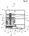
- the recipient of the in 13 shows a closing element 32 with axial pump outlet openings 54 whose outlet openings 48 are connected to an inlet connection 44 of the channel 34 .
- the channel 34 is formed in a separate cover 84 which serves to establish a connection between the pump outlet openings 54 of the pump 16 and the fore-vacuum connection 20 .
- the channel 34 has an outlet port 42 for establishing a connection between the pump outlet openings 54 of the pump 16 and the fore-vacuum port 20 .
- the cover 84 also has heat exchange elements 46, in particular cooling ribs. More than half of the surface of the connection element 32 is preferably provided with heat exchange elements 46 for optimal heat dissipation. As in 17 shown, an embodiment without heat exchange elements 46 is also conceivable, which reduces the manufacturing costs.
- the cover 84 not only fulfills the function of a connecting element and a cooling element, but also ensures that the high-vacuum pump 10 is secured and/or fixed in or on the recipient 10.
- the cover 84 can also have one or more fastening areas 70a, b.
- the cover 84 has a mounting portion 70a that partially surrounds the high vacuum pump 16 laterally, ie, in a direction perpendicular to the axial direction.
- Another fastening area 70b is located on a section of the cover 84 on the fore-vacuum connection side.
- the fastening areas 70a, b offer additional safety and stability in the event of a crash of the high-vacuum pump 16 by dissipating a burst torque to surrounding parts of the high-vacuum pump 16.
- the embodiment shown of a recipient 10 differs from that in 12 shown essentially in that the recipient 10 comprises six instead of three vacuum chambers 12.
- the high-vacuum pump 16 has a correspondingly larger number of pump stages.
- the channel 34 includes a second outlet connection 78 for establishing a connection between the fore-vacuum flange 20a and the channel 34.
- the second outlet connection 78 of the channel 34 thus provides a connection between the fore-vacuum chamber 24 and an inlet side of a fore-vacuum pump and a connection between the pump outlet openings 54 and a Input side of a backing pump.
- Port 42 acts as an input port here.
- a corresponding design is also conceivable in embodiments without a cover 84 .
- the fore-vacuum flange 20a is arranged on the underside of the closure element 32 next to the heat exchange elements 46 .
- the cover 84 can be assigned to the recipient 10 or be a component that closes off the pump receiving section 22 (see, e.g 14 ).
- the embodiment shown of a recipient 10 differs from that in 12 shown essentially in that the high-vacuum pump 16 does not have a cartridge housing 72 and the closing element 32 is axially covered by a cover 84 with a channel 34, which is located on the output side 36 of the high-vacuum pump 16 - or, with a corresponding design, directly on the pump receiving section 22 - and the fore-vacuum connection section 18 can be mounted.
- the recipient 10 can also comprise a common housing 28 which forms the vacuum chambers 12 and a substantial part of the pump receiving section 22 .
Landscapes
- Engineering & Computer Science (AREA)
- Mechanical Engineering (AREA)
- General Engineering & Computer Science (AREA)
- Non-Positive Displacement Air Blowers (AREA)
- Structures Of Non-Positive Displacement Pumps (AREA)
Priority Applications (2)
| Application Number | Priority Date | Filing Date | Title |
|---|---|---|---|
| EP22198845.4A EP4108932A1 (fr) | 2022-09-29 | 2022-09-29 | Reciate et pompe à vide élevé |
| JP2023081485A JP2024050401A (ja) | 2022-09-29 | 2023-05-17 | レシピエント及び高真空ポンプ |
Applications Claiming Priority (1)
| Application Number | Priority Date | Filing Date | Title |
|---|---|---|---|
| EP22198845.4A EP4108932A1 (fr) | 2022-09-29 | 2022-09-29 | Reciate et pompe à vide élevé |
Publications (1)
| Publication Number | Publication Date |
|---|---|
| EP4108932A1 true EP4108932A1 (fr) | 2022-12-28 |
Family
ID=83508788
Family Applications (1)
| Application Number | Title | Priority Date | Filing Date |
|---|---|---|---|
| EP22198845.4A Pending EP4108932A1 (fr) | 2022-09-29 | 2022-09-29 | Reciate et pompe à vide élevé |
Country Status (2)
| Country | Link |
|---|---|
| EP (1) | EP4108932A1 (fr) |
| JP (1) | JP2024050401A (fr) |
Cited By (1)
| Publication number | Priority date | Publication date | Assignee | Title |
|---|---|---|---|---|
| EP4293232A1 (fr) * | 2023-10-17 | 2023-12-20 | Pfeiffer Vacuum Technology AG | Pompe |
Citations (6)
| Publication number | Priority date | Publication date | Assignee | Title |
|---|---|---|---|---|
| US5733104A (en) * | 1992-12-24 | 1998-03-31 | Balzers-Pfeiffer Gmbh | Vacuum pump system |
| DE102006020710A1 (de) * | 2006-05-04 | 2007-11-08 | Pfeiffer Vacuum Gmbh | Vakuumpumpe mit Gehäuse |
| DE102007027354A1 (de) * | 2007-06-11 | 2008-12-18 | Oerlikon Leybold Vacuum Gmbh | Turbomolekularpumpe |
| DE102010032346A1 (de) * | 2010-07-27 | 2012-02-02 | Oerlikon Leybold Vacuum Gmbh | Turbomolekularpumpe sowie Turbomolekularpumpen-System |
| WO2013107667A1 (fr) * | 2012-01-21 | 2013-07-25 | Oerlikon Leybold Vacuum Gmbh | Pompe turbomoléculaire |
| WO2020208375A1 (fr) * | 2019-04-11 | 2020-10-15 | Edwards Limited | Module de chambre à vide |
-
2022
- 2022-09-29 EP EP22198845.4A patent/EP4108932A1/fr active Pending
-
2023
- 2023-05-17 JP JP2023081485A patent/JP2024050401A/ja active Pending
Patent Citations (6)
| Publication number | Priority date | Publication date | Assignee | Title |
|---|---|---|---|---|
| US5733104A (en) * | 1992-12-24 | 1998-03-31 | Balzers-Pfeiffer Gmbh | Vacuum pump system |
| DE102006020710A1 (de) * | 2006-05-04 | 2007-11-08 | Pfeiffer Vacuum Gmbh | Vakuumpumpe mit Gehäuse |
| DE102007027354A1 (de) * | 2007-06-11 | 2008-12-18 | Oerlikon Leybold Vacuum Gmbh | Turbomolekularpumpe |
| DE102010032346A1 (de) * | 2010-07-27 | 2012-02-02 | Oerlikon Leybold Vacuum Gmbh | Turbomolekularpumpe sowie Turbomolekularpumpen-System |
| WO2013107667A1 (fr) * | 2012-01-21 | 2013-07-25 | Oerlikon Leybold Vacuum Gmbh | Pompe turbomoléculaire |
| WO2020208375A1 (fr) * | 2019-04-11 | 2020-10-15 | Edwards Limited | Module de chambre à vide |
Cited By (1)
| Publication number | Priority date | Publication date | Assignee | Title |
|---|---|---|---|---|
| EP4293232A1 (fr) * | 2023-10-17 | 2023-12-20 | Pfeiffer Vacuum Technology AG | Pompe |
Also Published As
| Publication number | Publication date |
|---|---|
| JP2024050401A (ja) | 2024-04-10 |
Similar Documents
| Publication | Publication Date | Title |
|---|---|---|
| EP2829734B1 (fr) | Pompe à vide | |
| EP3657021B1 (fr) | Pompe à vide | |
| EP4108932A1 (fr) | Reciate et pompe à vide élevé | |
| EP4212730A1 (fr) | Pompe à vide avec étage de pompage de holward optimisé pour compenser la perte de performance liée à la température | |
| EP3617523A1 (fr) | Appareil à vide et système à vide | |
| EP3196471B1 (fr) | Pompe a vide | |
| EP3327293B1 (fr) | Pompe à vide avec une pluralté d'entrées | |
| EP3693610B1 (fr) | Pompe à vide moléculaire | |
| EP3628883B1 (fr) | Pompe à vide | |
| EP3734078B1 (fr) | Pompe turbomoléculaire et procédé de fabrication d'un disque de stator pour une telle pompe | |
| EP3670924B1 (fr) | Pompe à vide et procédé de fabrication d'une telle pompe à vide | |
| EP3564538B1 (fr) | Système à vide et procédé de fabrication d'un tel système à vide | |
| EP3730802B1 (fr) | Élément de bride | |
| EP3907406B1 (fr) | Pompe à vide | |
| EP3267040B1 (fr) | Pompe turbomoléculaire | |
| EP3845764B1 (fr) | Pompe à vide et système de pompe à vide | |
| EP3135932B1 (fr) | Pompe à vide et palier à aimant permanent | |
| EP3318763B1 (fr) | Étanchéité au vide, étanchéité double, système à vide et pompe à vide | |
| EP3561307B1 (fr) | Pompe à vide avec une bride de port d'aspiration et un support de palier dans le port d'aspiration | |
| DE102020116770B4 (de) | Vakuumpumpe mit integriertem miniaturventil | |
| EP3767109B1 (fr) | Système à vide | |
| EP3760872B1 (fr) | Pompe à vide pourvue d'un agencement de fixation destiné à l'application de la pompe à une structure de fixation ainsi qu'un poste de pompage doté d'une telle pompe à vide montée sur celui-ci | |
| EP4293232A1 (fr) | Pompe | |
| EP4194700A1 (fr) | Pompe à vide avec étage de pompe de holweck à géométrie de holweck variable | |
| EP4155549A1 (fr) | Pompe à vide à capacité d'aspiration améliorée de l'étage de pompage holweck |
Legal Events
| Date | Code | Title | Description |
|---|---|---|---|
| PUAI | Public reference made under article 153(3) epc to a published international application that has entered the european phase |
Free format text: ORIGINAL CODE: 0009012 |
|
| STAA | Information on the status of an ep patent application or granted ep patent |
Free format text: STATUS: THE APPLICATION HAS BEEN PUBLISHED |
|
| AK | Designated contracting states |
Kind code of ref document: A1 Designated state(s): AL AT BE BG CH CY CZ DE DK EE ES FI FR GB GR HR HU IE IS IT LI LT LU LV MC MK MT NL NO PL PT RO RS SE SI SK SM TR |
|
| STAA | Information on the status of an ep patent application or granted ep patent |
Free format text: STATUS: REQUEST FOR EXAMINATION WAS MADE |
|
| 17P | Request for examination filed |
Effective date: 20230330 |
|
| RBV | Designated contracting states (corrected) |
Designated state(s): AL AT BE BG CH CY CZ DE DK EE ES FI FR GB GR HR HU IE IS IT LI LT LU LV MC MK MT NL NO PL PT RO RS SE SI SK SM TR |
|
| STAA | Information on the status of an ep patent application or granted ep patent |
Free format text: STATUS: EXAMINATION IS IN PROGRESS |
|
| 17Q | First examination report despatched |
Effective date: 20230828 |