EP3617523A1 - Appareil à vide et système à vide - Google Patents
Appareil à vide et système à vide Download PDFInfo
- Publication number
- EP3617523A1 EP3617523A1 EP19156691.8A EP19156691A EP3617523A1 EP 3617523 A1 EP3617523 A1 EP 3617523A1 EP 19156691 A EP19156691 A EP 19156691A EP 3617523 A1 EP3617523 A1 EP 3617523A1
- Authority
- EP
- European Patent Office
- Prior art keywords
- vacuum device
- flange
- sealing
- axial
- sealing area
- Prior art date
- Legal status (The legal status is an assumption and is not a legal conclusion. Google has not performed a legal analysis and makes no representation as to the accuracy of the status listed.)
- Pending
Links
Images


Classifications
-
- F—MECHANICAL ENGINEERING; LIGHTING; HEATING; WEAPONS; BLASTING
- F04—POSITIVE - DISPLACEMENT MACHINES FOR LIQUIDS; PUMPS FOR LIQUIDS OR ELASTIC FLUIDS
- F04D—NON-POSITIVE-DISPLACEMENT PUMPS
- F04D19/00—Axial-flow pumps
- F04D19/02—Multi-stage pumps
- F04D19/04—Multi-stage pumps specially adapted to the production of a high vacuum, e.g. molecular pumps
- F04D19/042—Turbomolecular vacuum pumps
-
- F—MECHANICAL ENGINEERING; LIGHTING; HEATING; WEAPONS; BLASTING
- F04—POSITIVE - DISPLACEMENT MACHINES FOR LIQUIDS; PUMPS FOR LIQUIDS OR ELASTIC FLUIDS
- F04D—NON-POSITIVE-DISPLACEMENT PUMPS
- F04D29/00—Details, component parts, or accessories
- F04D29/08—Sealings
- F04D29/083—Sealings especially adapted for elastic fluid pumps
-
- F—MECHANICAL ENGINEERING; LIGHTING; HEATING; WEAPONS; BLASTING
- F04—POSITIVE - DISPLACEMENT MACHINES FOR LIQUIDS; PUMPS FOR LIQUIDS OR ELASTIC FLUIDS
- F04D—NON-POSITIVE-DISPLACEMENT PUMPS
- F04D29/00—Details, component parts, or accessories
- F04D29/60—Mounting; Assembling; Disassembling
- F04D29/601—Mounting; Assembling; Disassembling specially adapted for elastic fluid pumps
-
- F—MECHANICAL ENGINEERING; LIGHTING; HEATING; WEAPONS; BLASTING
- F04—POSITIVE - DISPLACEMENT MACHINES FOR LIQUIDS; PUMPS FOR LIQUIDS OR ELASTIC FLUIDS
- F04D—NON-POSITIVE-DISPLACEMENT PUMPS
- F04D29/00—Details, component parts, or accessories
- F04D29/70—Suction grids; Strainers; Dust separation; Cleaning
- F04D29/701—Suction grids; Strainers; Dust separation; Cleaning especially adapted for elastic fluid pumps
-
- F—MECHANICAL ENGINEERING; LIGHTING; HEATING; WEAPONS; BLASTING
- F04—POSITIVE - DISPLACEMENT MACHINES FOR LIQUIDS; PUMPS FOR LIQUIDS OR ELASTIC FLUIDS
- F04D—NON-POSITIVE-DISPLACEMENT PUMPS
- F04D19/00—Axial-flow pumps
- F04D19/02—Multi-stage pumps
- F04D19/04—Multi-stage pumps specially adapted to the production of a high vacuum, e.g. molecular pumps
- F04D19/048—Multi-stage pumps specially adapted to the production of a high vacuum, e.g. molecular pumps comprising magnetic bearings
Definitions
- the present invention relates to a vacuum device, in particular a turbomolecular pump, comprising a passage, namely an inlet or an outlet; and a flange for vacuum-tight connection of the passage of the vacuum device to another vacuum device in a connection direction along a connection axis; wherein the flange has a sealing region extending around the connecting axis for the contact of a sealing element; wherein the vacuum device has an axial end with respect to the connection axis radially within the sealing area in the connection direction.
- the invention further relates to a vacuum device, in particular a turbomolecular pump, with a flange for the vacuum-tight connection of the vacuum device to a further flange of a further vacuum device, the flange having a plurality of fastening points which are arranged distributed over a circumference of the flange, in particular with through openings for fastening elements to be assigned in each case, to which the flange can be fastened to the further flange, a sealing area surrounding the connection axis being provided on the flange for bearing a sealing element to be arranged between the flanges, the sealing area being arranged radially within the fastening points with respect to the connection axis.
- the invention also relates to a system with a vacuum device and a sealing element and in particular with a further vacuum device and / or at least one fastening element.
- a hybrid-mounted turbomolecular pump which is considered here as an example for vacuum devices of the types mentioned at the beginning, has two different bearing principles at the two rotor ends: on the fore-vacuum side, where higher pressures prevail, an oiled or grease-lubricated ball bearing is used.
- a permanent magnet bearing is used on the high vacuum side, where all hydrocarbons are to be avoided.
- a stator part of this permanent magnet bearing must be connected to the pump housing in some way in order to be able to perform its task. In most designs, the stator part is connected to the pump housing by the so-called star, i.e. a carrier in the inlet. Standard flange connections are preferred for connecting the high vacuum flange of the turbopump to a vacuum chamber.
- an O-ring is placed between the two flanges for sealing.
- it is usually located radially between two aluminum rings, one of which also takes over the centering function.
- This combination of O-ring and aluminum rings is generally called vacuum ring "centering ring”.
- grid-shaped inserts e.g. a protective grille and / or a splinter guard, which should prevent objects from falling into the turbopump. These are arranged above the star.
- the centering ring possibly with protective grille or splinter protection, is a generally available component and can be provided by various vacuum component manufacturers, in particular due to the standardization of the flanges.
- the object is achieved by a vacuum device with the features of claim 1, and in particular in that the sealing area of the flange with respect to the axial end of the vacuum device is axially set back against the connection direction or that the sealing area of the flange is arranged at the same axial position as the axial end of the vacuum device or that the sealing area of the flange is axially at most in the connection direction with respect to the axial end of the vacuum device 2 mm, in particular at most 1.5 mm, in particular at most 1 mm, or by at most 3 mm or by at most 4 mm.
- the invention also reduces the axial length of the vacuum device when the sealing area protrudes.
- the sealing area does not have to protrude as far as the axial end of the vacuum device due to the invention than in the prior art.
- a standardized flange connection has a largely fixed axial length.
- the sealing area is set back axially relative to the axial end of the vacuum device, or the sealing area of the flange is arranged at the same axial position as the axial end of the vacuum device, or the sealing area of the flange is axially at most 2 mm in the connection direction with respect to the axial end of the vacuum device by a maximum of 3 mm or by a maximum of 4 mm.
- the flange connection is displaced axially away from the passage and towards an axial center of the vacuum device, namely along the outside of the housing.
- the axial length which is necessary for the flange connection, is at least partially covered on the outside of the housing, where it does not lead to an axial extension of the vacuum device.
- the axial end of the vacuum device is displaced in the direction of or into the flange connection.
- a carrier and also the other components of the vacuum device can thus be arranged axially closer to the further vacuum device, so that axial installation space is saved as a result, and without sacrificing compatibility with the available standard flanges and accessories, i.e. sealing elements and fastening elements.
- the vacuum device can be, for example, a vacuum pump, in particular a turbomolecular pump.
- the passage can in particular be an inlet of the vacuum device.
- a vacuum device in the sense of the present application can not only be designed as an active device, as is the case, for example, with a turbomolecular pump, but can also be designed, for example, as a passive vacuum device.
- a passive vacuum device can be, for example, a pipe, a vacuum chamber or a valve.
- the axial end of the vacuum device is defined, for example, by a component arranged in the passage.
- This can be a carrier for a functional element of the vacuum device, for example.
- the functional element held by the carrier can, for example, be a component of a bearing element, in particular a magnetic bearing, in particular a stator part and / or inner ring.
- the axial end of the vacuum device can also be defined by a component defining the passage. This is, for example, the housing of the vacuum device and / or an area formed in one piece with the flange.
- the term component does not necessarily refer to a part that is separate from other components.
- the passage can be defined by the housing, which also comprises a flange connected in one piece.
- a component arranged in the passage can be connected either separately or in one piece to the component defining the passage, in particular the housing.
- a component, in particular a carrier for a functional element can be arranged in the passage and connected in one piece to the housing, or can also be designed separately therefrom.
- a component arranged in the passage such as a carrier, can be fixed to an inside of the component defining the passage, in particular the housing, and can be held axially, for example, by a shoulder of the component.
- the sealing area is set back with respect to the axial end of the vacuum device, arranged at the same axial position or protrudes by at most 2 mm or by at most 3 mm or by at most 4 mm, the axial end of the vacuum device being defined radially within the sealing area.
- the vacuum device can be designed radially beyond the sealing area or the flange connection and, for example, can project axially beyond the sealing area beyond it. But it is precisely the displacement of the radially inner axial end in the direction of or into the flange connection or the shifting back of the flange connection relative to this axial end that advantageously saves on axial installation space. Insofar as an axial end is referred to in the following, this means the one radially within the sealing region, unless stated otherwise.
- the sealing area is in particular designed as a flat annular surface, which is in particular perpendicular to the connection axis and / or connection direction.
- the sealing area can be radially delimited, for example, by a centering shoulder, in particular for a centering area of a sealing element designed as a centering ring.
- connection direction describes the direction which runs from the vacuum device to the further vacuum device to be connected, in particular along the connection axis.
- the sealing area is preferably set back against the direction of connection, that is to say, from the point of view of the further vacuum device, is preferably arranged axially behind the axial end of the claimed vacuum device.
- the axial distance between the axial end of the vacuum device and a recessed sealing area can be at least 5 mm, in particular at least 10 mm, in particular at least 15 mm.
- the axial distance between the end of the vacuum device and a recessed sealing area is at most 3 mm, in particular at most 2 mm.
- a sealing element for the flange connection is not considered part of the vacuum device for the purpose of unambiguous reference, in particular since such sealing elements are often sold independently of vacuum devices. After all, they are mostly standardized components.
- the invention includes embodiments that refer to the sealing element, which is why a system comprising a vacuum device according to one of the variants described above and a sealing element in or for contacting the sealing area of the vacuum device is also generally claimed.
- a sealing element is referred to below, an embodiment of the system is basically meant.
- the sealing area of the flange can also protrude axially by more than 2 mm with respect to the axial end of the vacuum device in the connecting direction, i.e. Refinements of this type are also the subject of the invention and are claimed.
- the sealing element has an axial end directed against the connection direction, which is axially set back at the same axial position as the axial end of the vacuum device or with respect to it.
- a protective element in particular a grid element, is connected to the sealing element, which spans the inlet.
- the sealing area can generally be arranged axially in such a way that a sealing element, to which a protective element spanning the inlet is connected, can be applied to the sealing area.
- a protective element can be provided on the vacuum device itself, so that the axial setback of the sealing area can be larger and more installation space is saved because it is not necessary for a protective element to be arranged on the sealing element.
- the sealing element has an axial thickness when installed in the flange connection, the axial distance between the axial end of the vacuum device and the sealing area being at most half the thickness of the sealing element. This also improves compatibility with standard components.
- the sealing element can be formed by a centering ring.
- the sealing element can comprise, for example, an elastomer seal and / or an O-ring.
- a metal seal can also be used as the sealing element, for example.
- the axial end of the vacuum device is preferably not only defined radially inside the sealing area, but also radially inside the sealing element.
- the flange is preferably arranged on a housing of the vacuum device, in particular connected to it in one piece, for example welded or made from a common blank.
- the housing defines in particular the passage.
- An axial end of a housing of the vacuum device can preferably correspond in its axial position to that of a component arranged in the passage or can be axially set back in relation to the opposite direction of connection his.
- the axial housing end can be arranged in the axial direction between the axial end of the component arranged in the passage and the sealing area.
- the object is also achieved by a vacuum device according to claim 5, and in particular in that, with respect to the connection axis, an axial projection is provided on the flange radially outside the sealing area, which projection forms a contact surface for the further flange.
- the projection and the contact surface support the flange connection.
- the system is provided in addition to and separately from the sealing element, in particular a centering ring, so that the system prevents a tilting deformation of at least one flange on the sealing element.
- a flange connection of the type ISO-F in particular in accordance with ISO 1609 or DIN 28404, is provided, the flange being intended to be fastened to a further flange with a centering ring.
- the further flange can generally also be referred to as a counter flange.
- the centering ring is the fulcrum of the lever. This can lead to a displacement of a functional element, such as a permanent magnet bearing, via a carrier or star.
- the approach on which the invention is based reduces, in particular prevents, deformation of the flanges.
- the flange and counterflange are supported against one another outside the fastening points or force introduction points, in particular outside the sealing area and / or the seat of a centering ring, preferably by at least the axial thickness of the centering ring, but in particular by less than the unloaded thickness of an im Centering ring located O-rings.
- the flange is thus extended to a certain extent by the projection in the direction of the counter flange.
- the non-deformable elements of the centering ring thus lie in a recessed recess in the passage defined by the flange, in particular the inlet.
- the recess can be made, for example, in a simple manner by turning.
- the invention therefore provides in particular that the flange with its contact surface lies directly on the counter flange or at least on a component supporting the counter flange. Deformation of the flanges and the components connected to them is thus reduced, in particular avoided, in particular independently of a force of at least one fastening element, in particular a tightening torque of fastening screws.
- the contact surface forms, in particular, a counter bearing for the lever between the fastening point and the sealing element, in particular the centering ring.
- An O-ring which is preferably located in the centering ring, is in particular thicker than the axial height of the contact surface in relation to the sealing area or the projection. The connection is nevertheless reliably sealed.
- the contact surface and / or the projection is provided radially outside the fastening points, but not necessarily but optionally only there. This further improves the support of the counter flange.
- a lever between the fastening element and the sealing element is supported in a particularly reliable manner.
- the protrusion can be formed, for example, all around the connection axis or by a plurality of protrusions, in particular distributed over the circumference.
- the projection can be designed, for example, as a web.
- a projection or a contact surface can not only be arranged radially outside the sealing area or the fastening points.
- a bearing surface and / or a projection can also be provided radially inside the fastening points, or the bearing and / or projection can extend radially inside from the outside of the fastening points.
- the contact surface and / or projection can be located radially in the region of a fastening element, in particular a screw shaft, and / or can also be arranged radially outside and / or inside thereof.
- the fastening points are the points which are defined by the intersection of an axis of a respective fastening element with the connection plane which runs perpendicular to the connection axis. The axial position of the point or the plane is of secondary importance. Simplified, one can also speak of radially outside or within axes of the fastening elements.
- the axis and / or a screw shank may or may not itself be radially free from the projection or the contact surface.
- the attachment points or axes of through openings in the flange and / or fasteners to be assigned.
- the contact surface extends up to a radial outer edge of the flange, in particular is only arranged on the radial outer edge and / or is radially spaced from the sealing area and / or fastening point or element, in particular a fastening axis thereof or a screw shaft.
- the contact surface and / or the projection can, for example, be connected in one piece to the flange or be formed by a component separate therefrom.
- the projection or web can be designed as a separate ring.
- the separate system can be flexibly removed by the customer, e.g. if he wants to do without a centering ring because e.g. the counter flange has a groove for receiving a sealing element.
- the contact surface can be arranged axially protruding with respect to the sealing area, in particular in a connection direction.
- the contact surface is advantageously arranged axially between the sealing area and a vacuum device to be connected.
- an axial distance between the system and the sealing area is at least 3.7 mm and at most 4.1 mm, in particular 3.9 mm, or at least 5.4 mm and at most 5.8 mm, in particular 5.6 mm. This results in particularly good support and particularly low flange deformation with a good sealing effect.
- the projection is essentially circumferential with respect to the connection axis, an opening being provided in the projection or a groove in the contact surface, which is extends from a radially inner end of the projection or the contact surface to a radially outer end of the projection or the contact surface.
- a system comprising a vacuum device according to at least one of the variants described above and a sealing element in or for contacting the sealing area of the vacuum device.
- an axial distance between the contact surface and the sealing area corresponds to an axial thickness or height of the sealing element when installed in the flange connection. This results in a particularly low deformation of the flange and connected components.
- the axial distance can correspond to an axial height of a fixed part of a sealing element, in particular designed as a centering ring.
- the axial distance can also correspond, for example, to the axial height of a metal seal.
- the flange can, for example, be connected to a housing of the vacuum device, the flange preferably being formed in one piece with the housing.
- the advantages according to the invention unfold to a particularly high degree.
- the flange can preferably be an inlet flange of the vacuum device, in particular a vacuum pump.
- the improved vacuum tightness has a positive effect here due to the low pressures compared to the outlet.
- the sealing element can thus in particular be formed by a centering ring, the centering ring in particular comprising a deformable sealing member, preferably an O-ring, and an at least substantially rigid holder for the sealing member.
- the sealing element can be designed, for example, as a metal seal.
- the sealing element can be a standard component.
- the vacuum device is designed as a turbomolecular pump with a bearing element, in particular a magnetic bearing, a carrier for a component of the bearing element being connected to the flange and / or to a housing of the turbomolecular pump.
- the reduction in flange deformation according to the invention has a particularly improving effect here on the service life of the pump, since the rotor positioning can largely be maintained exactly.
- a vacuum device according to one of the aspects described above, preferably according to an embodiment described therefor, with a flange, and a sealing element in or for contacting the sealing area of the vacuum device includes.
- active and passive vacuum devices can be used as vacuum devices.
- the system can further comprise a further vacuum device to be connected or connected with a further flange or counter flange.
- the system can also have at least one fastening element for fastening the flange of the vacuum device on the further flange of the further vacuum device, in particular a set of fastening elements.
- the sealing element can in particular be designed to be arranged between respective, opposite sealing regions of the flanges, in particular compressed, or can be arranged in this way.
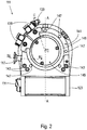
- the turbomolecular pump 111 shown comprises a pump inlet 115 surrounded by an inlet flange 113, to which a recipient, not shown, can be connected in a manner known per se.
- the gas from the recipient can be sucked out of the recipient via the pump inlet 115 and conveyed through the pump to a pump outlet 117, to which a backing pump, such as a rotary vane pump, can be connected.
- the inlet flange 113 forms in accordance with the orientation of the vacuum pump Fig. 1 the upper end of the housing 119 of the vacuum pump 111.
- the housing 119 comprises a lower part 121, on which an electronics housing 123 is arranged on the side. Electrical and / or electronic components of the vacuum pump 111 are accommodated in the electronics housing 123, for example for operating an electric motor 125 arranged in the vacuum pump.
- Several connections 127 for accessories are provided on the electronics housing 123.
- a data interface 129 for example in accordance with the RS485 standard, and a power supply connection 131 are arranged on the electronics housing 123.
- a flood inlet 133 in particular in the form of a flood valve, is provided on the housing 119 of the turbomolecular pump 111, via which the vacuum pump 111 can be flooded.
- a sealing gas connection 135, which is also referred to as a purge gas connection via which purge gas to protect the electric motor 125 (see, for example, FIG Fig. 3 ) before that, pumped gas can be brought into the engine compartment 137, in which the electric motor 125 is housed in the vacuum pump 111.
- two coolant connections 139 are arranged in the lower part 121, one of the coolant connections being provided as an inlet and the other coolant connection being provided as an outlet for coolant, which can be guided into the vacuum pump for cooling purposes.
- the lower side 141 of the vacuum pump can serve as a standing surface, so that the vacuum pump 111 can be operated standing on the underside 141.
- the vacuum pump 111 can also be attached to a recipient via the inlet flange 113 and can thus be operated in a manner of hanging.
- the vacuum pump 111 can be designed so that it can also be operated if it is aligned in a different way than in FIG Fig. 1 is shown.
- Embodiments of the vacuum pump can also be realized, in which the underside 141 cannot be arranged facing downwards, but turned to the side or directed upwards.
- various screws 143 are also arranged, by means of which components of the vacuum pump which are not further specified here are fastened to one another.
- a bearing cover 145 is attached to the underside 141.
- Fastening bores 147 are also arranged on the underside 141, via which the pump 111 can be fastened, for example, to a support surface.
- a coolant line 148 is shown in which the coolant introduced and discharged via the coolant connections 139 can circulate.
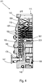
- the vacuum pump comprises a plurality of process gas pump stages for conveying the process gas present at the pump inlet 115 to the pump outlet 117.
- a rotor 149 is arranged in the housing 119 and has a rotor shaft 153 rotatable about an axis of rotation 151.
- the turbomolecular pump 111 comprises a plurality of turbomolecular pump stages connected in series with one another in a pumping manner, with a plurality of radial rotor disks 155 fastened to the rotor shaft 153 and stator disks 157 arranged between the rotor disks 155 and fixed in the housing 119.
- a rotor disk 155 and an adjacent stator disk 157 each form a turbomolecular one Pump stage.
- the stator disks 157 are held at a desired axial distance from one another by spacer rings 159.
- the vacuum pump also comprises Holweck pump stages which are arranged one inside the other in the radial direction and have a pumping effect and are connected in series with one another.
- the rotor of the Holweck pump stages comprises a rotor hub 161 arranged on the rotor shaft 153 and two cylindrical jacket-shaped Holweck rotor sleeves 163, 165 fastened to and supported by the rotor hub 161, which are oriented coaxially to the axis of rotation 151 and nested one inside the other in the radial direction.
- two cylindrical jacket-shaped Holweck stator sleeves 167, 169 are provided, which are also oriented coaxially to the axis of rotation 151 and are nested one inside the other in the radial direction.
- the pump-active surfaces of the Holweck pump stages are formed by the lateral surfaces, that is to say by the radial inner and / or outer surfaces, of the Holweck rotor sleeves 163, 165 and of the Holweck stator sleeves 167, 169.
- the radial inner surface of the outer Holweck stator sleeve 167 lies opposite the radial outer surface of the outer Holweck rotor sleeve 163, forming a radial Holweck gap 171 and forms the first Holweck pumping stage following the turbomolecular pumps.
- the radial inner surface of the outer Holweck rotor sleeve 163 faces the radial outer surface of the inner Holweck stator sleeve 169 with the formation of a radial Holweck gap 173 and forms a second Holweck pump stage with the latter.
- the radial inner surface of the inner Holweck stator sleeve 169 lies against the radial outer surface of the inner Holweck rotor sleeve 165 opposite to form a radial Holweck gap 175 and forms the third Holweck pumping stage with this.
- a radially extending channel can be provided, via which the radially outer Holweck gap 171 is connected to the central Holweck gap 173.
- a radially extending channel can be provided at the upper end of the inner Holweck stator sleeve 169, via which the central Holweck gap 173 is connected to the radially inner Holweck gap 175.
- a connection channel 179 to the outlet 117 can also be provided.
- the aforementioned pump-active surfaces of the Holweck stator sleeves 163, 165 each have a plurality of Holweck grooves running spirally around the axis of rotation 151 in the axial direction, while the opposite lateral surfaces of the Holweck rotor sleeves 163, 165 are smooth and the gas for operating the Drive the vacuum pump 111 in the Holweck grooves.
- a roller bearing 181 is provided in the area of the pump outlet 117 and a permanent magnet bearing 183 in the area of the pump inlet 115.
- a conical spray nut 185 is provided on the rotor shaft 153 with an outer diameter increasing toward the roller bearing 181.
- the injection nut 185 is in sliding contact with at least one scraper of an operating fluid reservoir.
- the operating medium storage comprises a plurality of absorbent disks 187 stacked one on top of the other, which are impregnated with an operating medium for the roller bearing 181, for example with a lubricant.
- the operating medium is transferred by capillary action from the operating medium storage via the wiper to the rotating spray nut 185 and, as a result of the centrifugal force along the spray nut 185, is conveyed in the direction of the increasing outer diameter of the spray nut 185 to the roller bearing 181, where it e.g. fulfills a lubricating function.
- the roller bearing 181 and the operating fluid reservoir are enclosed in the vacuum pump by a trough-shaped insert 189 and the bearing cover 145.
- the permanent magnet bearing 183 comprises a bearing half 191 on the rotor side and a bearing half 193 on the stator side, each of which comprises an annular stack of a plurality of permanent magnetic rings 195, 197 stacked on one another in the axial direction.
- the ring magnets 195, 197 lie opposite one another to form a radial bearing gap 199, the rotor-side ring magnets 195 being arranged radially on the outside and the stator-side ring magnets 197 being arranged radially on the inside.
- the magnetic field present in the bearing gap 199 causes magnetic repulsive forces between the ring magnets 195, 197, which cause the rotor shaft 153 to be supported radially.
- the rotor-side ring magnets 195 are carried by a carrier section 201 of the rotor shaft 153, which radially surrounds the ring magnets 195 on the outside.
- the stator-side ring magnets 197 are carried by a stator-side carrier section 203 which extends through the ring magnets 197 and is suspended from radial struts 205 of the housing 119.
- Parallel to the axis of rotation 151, the rotor-side ring magnets 195 are fixed by a cover element 207 coupled to the carrier section 203.
- the stator-side ring magnets 197 are fixed parallel to the axis of rotation 151 in one direction by a fastening ring 209 connected to the carrier section 203 and a fastening ring 211 connected to the carrier section 203.
- a plate spring 213 can also be provided between the fastening ring 211 and the ring magnet 197.
- An emergency or catch bearing 215 is provided within the magnetic bearing, which runs empty without contact during normal operation of the vacuum pump 111 and only comes into engagement with an excessive radial deflection of the rotor 149 relative to the stator in order to provide a radial stop for the rotor 149 to form, since a collision of the rotor-side structures with the stator-side structures is prevented.
- the catch bearing 215 is designed as an unlubricated roller bearing and forms a radial gap with the rotor 149 and / or the stator, which causes the catch bearing 215 to be disengaged in normal pumping operation.
- the radial deflection at which the catch bearing 215 engages is dimensioned large enough that the catch bearing 215 does not engage during normal operation of the vacuum pump, and at the same time is small enough so that the rotor-side structures collide with the stator-side structures under all circumstances is prevented.
- the vacuum pump 111 comprises the electric motor 125 for rotatingly driving the rotor 149.
- the armature of the electric motor 125 is formed by the rotor 149, the rotor shaft 153 of which extends through the motor stator 217.
- a permanent magnet arrangement can be arranged radially on the outside or embedded on the section of the rotor shaft 153 which extends through the motor stator 217.
- an intermediate space 219 is arranged which comprises a radial motor gap, via which the motor stator 217 and the permanent magnet arrangement for transmitting the drive torque can magnetically influence one another.
- the motor stator 217 is fixed in the housing within the motor space 137 provided for the electric motor 125.
- a sealing gas which is also referred to as a purge gas and which can be, for example, air or nitrogen, can enter the engine compartment 137 via the sealing gas connection 135.
- the electric motor 125 can use process gas, for example, in front of process gas Corrosive parts of the process gas are protected.
- the engine compartment 137 can also be evacuated via the pump outlet 117, ie in the engine compartment 137 there is at least approximately the vacuum pressure caused by the fore-vacuum pump connected to the pump outlet 117.
- a so-called labyrinth seal 223, which is known per se, can also be provided between the rotor hub 161 and a wall 221 delimiting the motor space 137, in particular in order to achieve a better seal of the motor space 217 with respect to the radially outside Holweck pump stages.
- a turbomolecular pump of the prior art is shown in a sectional view.
- a partial view has been selected that shows an inlet flange 20.
- the flange 20 is part of a housing 22 and is used for connection to a further vacuum device, not shown, for example a vacuum chamber.
- the flange 20 is designed as an ISO-K flange in this example. It is connected to a further flange of the vacuum device to be connected, not shown, via separate fastening elements, also not shown, which grip around the flanges in the manner of a clamp. A respective fastening element engages behind a circumferential projection 24 of the flange 20.
- a centering ring 26 bears against the flange 20.
- This comprises an O-ring 28 which is radially enclosed between two fixed, in particular metallic, ring elements 30.
- the centering ring 26 thus forms a sealing element for the flange connection.
- the centering ring 26 further comprises a protective element designed as a grid element 32, which spans an inlet 34 defined by the flange 20, so that an interior of the pump is protected against foreign bodies.
- a carrier 36 which carries a functional element 38, here a static part of a bearing and specifically a set of inner permanent magnets of a magnetic bearing.
- the carrier 36 is supported on the housing 22, namely on the inside thereof. Axially, the carrier 36 is fixed to a shoulder of the housing 22 enclosing the passage 34.
- the centering ring 26 lies with its ring elements 30 and the O-ring 28 against a sealing area 40 of the flange 20.
- the sealing region 40 defines a circumferential annular surface which faces another flange, not shown, of a vacuum device to be connected.
- the further flange also comprises a corresponding sealing area.
- connection direction 43 runs along the connection axis 42 and from the vacuum device shown to the further vacuum device (not shown), that is to say in the direction in which the vacuum device is attached to the further vacuum device.
- the sealing area 40 extends in a plane that runs perpendicular to the connecting axis 42.
- the connection axis 42 coincides in this example and generally advantageously with a rotor axis of the pump.
- FIG. 7 A turbomolecular pump with a flange 20 according to the first aspect of the invention is shown.
- a sealing area 40 of the flange 20 is set back axially with respect to an axial end of the vacuum device in the opposite direction of the connection 43.
- the axial end of the vacuum device is axially between the further vacuum device, not shown, and the sealing region 40 of the flange 20.
- the axial end of the vacuum device is formed both by the carrier 36 and by the housing 22 or a section of the same delimiting the passage 34, since both have their axial end at the same axial height.
- the axial distance 44 between the axial end of the vacuum device and the sealing area 40 is thus in comparison to the vacuum pump according to Fig. 6 negative and therefore labeled "-".
- the sealing area 40 or the flange 20 are thus arranged set back with respect to the axial end of the vacuum device. In other words, the sealing area 40 and the flange 20 are compared between the 6 and 7 moved down along the housing 22. Conversely, the carrier 36 and the axial housing end are displaced into the flange connection. This results in a reduced axial length of the pump corresponding to the distance 44 in the connected state.
- the centering ring 26 does not comprise a protective or grating element spanning the inlet 34.
- a protective or grid element that is independent of the sealing element can also be provided, which is fastened, for example, to the carrier 36 and / or to the housing 22. The advantages of a protective element can thus be combined with the advantage of a large space saving.
- the 8 and 9 on the other hand show a turbomolecular pump with a flange 20 according to the first aspect for a centering ring 26 with a grid element 32 Fig. 8 the centering ring 26 prior to application to the sealing area 40 while Fig. 9 shows the centering ring 26 in the applied or installed state.
- An axial distance between the axial end of the vacuum device and the sealing area 40 is again designated 44 and is also negative here.
- the distance 44 is significantly smaller than in the embodiment according to FIG Fig. 7 , The distance 44 is selected here such that the centering ring 26 can be placed against the sealing area 40 despite the grid element 32.
- the distance 44 can also be zero or at most +2 mm or at most 3 mm or at most 4 mm.
- Fig. 9 it can be seen that, in the embodiment shown, the grid element 32 essentially abuts the axial end of the carrier 36 and the axial housing end. Basically, however, embodiments are also conceivable in which there is a distance between the grating element 32 and the axial end of the vacuum device or the carrier and / or housing end, but the axial space saving can be smaller.
- the axial support end 36 coincides with an axial end of the housing 22 facing the further vacuum device.
- the relevant ends can also have different axial positions, in particular the axial housing end can be arranged axially behind the carrier end from the point of view of the further vacuum device.
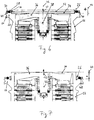
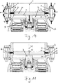
- the second aspect is in the 10 to 14 illustrated. It shows Fig. 10 a vacuum device designed as a turbomolecular pump of the prior art.
- at least one counter flange 46 is designed as an ISO-F flange.
- the turbomolecular pump according to Fig. 10 comprises a flange 20 which is arranged on a housing 22.
- the flange 20 surrounds an inlet 34 of the pump.
- a carrier 36 is arranged in the inlet and carries a functional element 38, which in turn is designed as a stator part of a magnetic bearing.
- the carrier 36 is connected in one piece to the housing 22 or the flange 20, but can in principle also, for example, as in FIGS 6 to 9 indicated in the drawing, be formed as a separate part.
- the flange 20 is connected to a counter flange 46, which is part of a housing 48 of a further vacuum device, which is otherwise not shown.
- the flanges 20 and 46 are of the ISO-F type.
- the flanges 20, 46 have through openings 50 for fastening elements 52.
- the through openings 50 and fastening elements 52 are distributed over the circumference of the bottle 20, 46 around a connecting axis 42 and define respective fastening points.
- a respective connecting element 52 is formed here by a screw 54 with a screw shaft 56 and by a corresponding nut 58.
- the flanges 20, 46 are braced against one another by the fastening element 52 or the screw 54 in connection with the nut 58, a sealing element, here a centering ring 26, being clamped in the axial direction.
- a sealing element here a centering ring 26
- an O-ring 28 of the centering ring 26 is compressed up to an axial height in accordance with the ring elements 30 adjacent to the O-ring.
- the forces introduced by the fastening elements 52 and the forces resulting therefrom are indicated by several arrows.
- the fastening elements 52 initially produce a tensile force along a respective fastening axis 60.
- centering ring 26 with its ring elements 30 is to be regarded as essentially fixed in the axial direction, this results in a certain deformation of the outer flange ends of the flanges 20, 46 towards one another, with a leverage effect between the fastening element 52 and the centering ring 26.
- the deformation of the flange ends towards one another can, on the one hand, cause problems with regard to vacuum tightness, since the accuracy of the centering ring 26 in contact with sealing regions 40 of the flanges 20, 46 is generally disturbed.
- the deformation of the flange 20 can result in a change in position or deformation of the carrier 36 and thus of the functional element 38, as is indicated by the downward-pointing arrow on the connecting axis 42.
- the axial positioning of the magnetic bearing inner ring and the rotor of the turbomolecular pump are thus disturbed, which can result in increased wear.
- FIG. 11 An embodiment of the invention according to the first aspect is in Fig. 11 shown.
- a sealing area 40 which extends circumferentially with respect to the connection axis 42 for bearing a sealing element 26 which is arranged between the flanges 20, 46 and which is arranged radially within the fastening points or axes 60 with respect to the connection axis 42.
- an axial projection 62 is provided on the flange 20 radially outside the sealing region 40, which has a contact surface 64 for the further flange 46.
- Fig. 10 shows that the projection 62 or the contact surface 64 support the outer ends of the flanges 20, 46 against each other, so that in There is essentially no deformation, primarily no bending around the sealing element or centering element 26.
- the accuracy of the contact of the sealing element 26 with the sealing area 40 is improved and, on the other hand, it prevents deformations or changes in position from occurring on components connected to the flanges 20, 46, in particular on the carrier 36.
- wear is reduced and the Lifespan increased because the axial position of the inner ring of the magnetic bearing and the rotor thus better meet the design requirements.
- Projection 62 and contact surface 64 extend in the radial direction from inside the fastening points 60 to outside the fastening points 60 and even to an outer end of the flanges 20, 46.
- the projection 62 or contact 64 can also only extend radially inside or outside the fastening points 60 extend, the latter variant below using the 13 and 14 is illustrated in more detail.
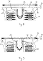
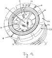
- Fig. 12 is the embodiment according to Fig. 11 illustrated in more detail in perspective view, counter flange 46 and fastening elements 52 are not shown.
- the view of the Fig. 12 corresponds to a look into the inlet 34 of the pump.
- the flange 20 with its contact surface 64 is visible.
- a plurality of through openings 50 are arranged distributed over the circumference of the flange 20.
- the through openings 50 are designed here as recesses open to the outside and as elongated holes.
- through openings 50 which are closed with respect to the outer edge would also be conceivable, for example.
- the flanges can in principle be free of through-openings, wherein clamp-like fastening elements can preferably be provided which encompass the flanges.
- the carrier 36 in the inlet 34 is also clearly visible. In this embodiment, this comprises three webs which extend between an inner wall of the housing 22 and a central region of the carrier 36. The central area carries the functional element 38.
- a carrier 36 is also referred to as a star.
- the centering ring 26 with its ring elements 30 and the O-ring 28 is inserted into the flange 20.
- Two grooves 66 are formed in the system 64, which extend from a radially inner end of the system 64 to a radially outer end of the system 64. In the present embodiment, the grooves 66 extend largely exactly radially. Another number of such grooves 66 can also be provided. The grooves 66 provide access for a leak detection gas to the sealing element or centering ring 26 and to the sealing area 40.
- FIG. 13 Another embodiment of a vacuum device, again designed as a turbomolecular pump, according to the second aspect is shown in Fig. 13 shown.
- This stands out in comparison to the embodiment of the Fig. 11 and 12 characterized in that an axial projection 62 of the flange 20 with its contact surface 64 for the counter flange 46 is only arranged radially outside the fastening points 60.
- the projection 62 and the contact surface 64 are arranged only on the outer edge of the flange 20, but an arrangement somewhat further inward with respect to the outer edge would also be conceivable.
- the axial projection 62 is connected in one piece to the flange 20, in particular by turning.
- the projection 62 is formed by a separate component.
- the separate component can, for example, be firmly connected to the flange 20, for example via an interference fit between the flange 20 and the illustrated, downwardly directed web of the separate one Component or projection 62.
- the separate component can only be applied to the flange 20. Nevertheless, it reliably supports the flange 46 according to the invention against the flange 20 with the contact surface 64.
Landscapes
- Engineering & Computer Science (AREA)
- Mechanical Engineering (AREA)
- General Engineering & Computer Science (AREA)
- Non-Positive Displacement Air Blowers (AREA)
Priority Applications (2)
| Application Number | Priority Date | Filing Date | Title |
|---|---|---|---|
| EP19156691.8A EP3617523A1 (fr) | 2019-02-12 | 2019-02-12 | Appareil à vide et système à vide |
| JP2020016016A JP7111754B2 (ja) | 2019-02-12 | 2020-02-03 | 真空装置及び真空システム |
Applications Claiming Priority (1)
| Application Number | Priority Date | Filing Date | Title |
|---|---|---|---|
| EP19156691.8A EP3617523A1 (fr) | 2019-02-12 | 2019-02-12 | Appareil à vide et système à vide |
Publications (1)
| Publication Number | Publication Date |
|---|---|
| EP3617523A1 true EP3617523A1 (fr) | 2020-03-04 |
Family
ID=65433474
Family Applications (1)
| Application Number | Title | Priority Date | Filing Date |
|---|---|---|---|
| EP19156691.8A Pending EP3617523A1 (fr) | 2019-02-12 | 2019-02-12 | Appareil à vide et système à vide |
Country Status (2)
| Country | Link |
|---|---|
| EP (1) | EP3617523A1 (fr) |
| JP (1) | JP7111754B2 (fr) |
Cited By (2)
| Publication number | Priority date | Publication date | Assignee | Title |
|---|---|---|---|---|
| US20220389933A1 (en) * | 2021-06-02 | 2022-12-08 | Shimadzu Corporation | Vacuum pump and leak detector |
| GB2623527A (en) * | 2022-10-18 | 2024-04-24 | Edwards Ltd | Turbomolecular pump |
Citations (9)
| Publication number | Priority date | Publication date | Assignee | Title |
|---|---|---|---|---|
| US4950000A (en) * | 1987-11-17 | 1990-08-21 | Furmanite International Ltd. | Flanged pipeline connections |
| US6485254B1 (en) * | 2000-10-19 | 2002-11-26 | Applied Materials, Inc. | Energy dissipating coupling |
| US20050204754A1 (en) * | 2004-03-22 | 2005-09-22 | Alcatel | Vacuum pump damping adapter |
| US20070125515A1 (en) * | 2005-12-02 | 2007-06-07 | Pfeiffer Vacuum Gmbh | Vacuum housing |
| US20080226387A1 (en) * | 2004-12-20 | 2008-09-18 | Boc Edwarda Japan Limited | Structure for Connecting End Parts and Vacuum System Using the Structure |
| EP2149710A2 (fr) * | 2008-07-31 | 2010-02-03 | Pfeiffer Vacuum Gmbh | Agencement de pompe à vide |
| DE102009039120A1 (de) * | 2009-08-28 | 2011-03-03 | Pfeiffer Vacuum Gmbh | Vakuumpumpe |
| US20150060691A1 (en) * | 2013-08-29 | 2015-03-05 | Varian Semiconductor Equipment Associates, Inc. | Semiconductor process pumping arrangements |
| EP3034881A1 (fr) * | 2014-12-18 | 2016-06-22 | Pfeiffer Vacuum GmbH | Pompe à vide |
Family Cites Families (4)
| Publication number | Priority date | Publication date | Assignee | Title |
|---|---|---|---|---|
| JP4780859B2 (ja) | 2000-12-18 | 2011-09-28 | 日機装株式会社 | キャンドモータポンプ |
| JP2003148381A (ja) | 2001-11-16 | 2003-05-21 | Boc Edwards Technologies Ltd | 真空ポンプ |
| EP3244068B1 (fr) | 2016-05-10 | 2020-01-01 | Pfeiffer Vacuum Gmbh | Pompe à vide |
| JP6882623B2 (ja) | 2017-03-21 | 2021-06-02 | 株式会社島津製作所 | センターリングおよび真空ポンプ |
-
2019
- 2019-02-12 EP EP19156691.8A patent/EP3617523A1/fr active Pending
-
2020
- 2020-02-03 JP JP2020016016A patent/JP7111754B2/ja active Active
Patent Citations (9)
| Publication number | Priority date | Publication date | Assignee | Title |
|---|---|---|---|---|
| US4950000A (en) * | 1987-11-17 | 1990-08-21 | Furmanite International Ltd. | Flanged pipeline connections |
| US6485254B1 (en) * | 2000-10-19 | 2002-11-26 | Applied Materials, Inc. | Energy dissipating coupling |
| US20050204754A1 (en) * | 2004-03-22 | 2005-09-22 | Alcatel | Vacuum pump damping adapter |
| US20080226387A1 (en) * | 2004-12-20 | 2008-09-18 | Boc Edwarda Japan Limited | Structure for Connecting End Parts and Vacuum System Using the Structure |
| US20070125515A1 (en) * | 2005-12-02 | 2007-06-07 | Pfeiffer Vacuum Gmbh | Vacuum housing |
| EP2149710A2 (fr) * | 2008-07-31 | 2010-02-03 | Pfeiffer Vacuum Gmbh | Agencement de pompe à vide |
| DE102009039120A1 (de) * | 2009-08-28 | 2011-03-03 | Pfeiffer Vacuum Gmbh | Vakuumpumpe |
| US20150060691A1 (en) * | 2013-08-29 | 2015-03-05 | Varian Semiconductor Equipment Associates, Inc. | Semiconductor process pumping arrangements |
| EP3034881A1 (fr) * | 2014-12-18 | 2016-06-22 | Pfeiffer Vacuum GmbH | Pompe à vide |
Cited By (3)
| Publication number | Priority date | Publication date | Assignee | Title |
|---|---|---|---|---|
| US20220389933A1 (en) * | 2021-06-02 | 2022-12-08 | Shimadzu Corporation | Vacuum pump and leak detector |
| US11754081B2 (en) * | 2021-06-02 | 2023-09-12 | Shimadzu Corporation | Vacuum pump and leak detector |
| GB2623527A (en) * | 2022-10-18 | 2024-04-24 | Edwards Ltd | Turbomolecular pump |
Also Published As
| Publication number | Publication date |
|---|---|
| JP7111754B2 (ja) | 2022-08-02 |
| JP2020133628A (ja) | 2020-08-31 |
Similar Documents
| Publication | Publication Date | Title |
|---|---|---|
| EP0408791B1 (fr) | Pompe à effet visqueux à rotor en forme de cloche | |
| EP1725775A1 (fr) | Ensemble comprenant un moteur a induit exterieur a commutation electronique | |
| EP2994644B1 (fr) | Ensemble pompe pourvu d'un ensemble palier lisse | |
| EP3657021B1 (fr) | Pompe à vide | |
| EP3617523A1 (fr) | Appareil à vide et système à vide | |
| EP2610498B1 (fr) | Groupe motopompe | |
| DE102010024302A1 (de) | Elektromotor und Verfahren zum Herstellen eines Elektromotors | |
| EP4212730A1 (fr) | Pompe à vide avec étage de pompage de holward optimisé pour compenser la perte de performance liée à la température | |
| EP3540237B1 (fr) | Connection de brides d'usage facile pour dispositif à vide | |
| DE102015104438B4 (de) | Vakuumsystem | |
| EP3730802B1 (fr) | Élément de bride | |
| EP3734078B1 (fr) | Pompe turbomoléculaire et procédé de fabrication d'un disque de stator pour une telle pompe | |
| EP3327293B1 (fr) | Pompe à vide avec une pluralté d'entrées | |
| EP3561307B1 (fr) | Pompe à vide avec une bride de port d'aspiration et un support de palier dans le port d'aspiration | |
| EP3318763B1 (fr) | Étanchéité au vide, étanchéité double, système à vide et pompe à vide | |
| EP3267040B1 (fr) | Pompe turbomoléculaire | |
| EP3628883B1 (fr) | Pompe à vide | |
| EP3683447A1 (fr) | Pompe à vide | |
| EP4325061A1 (fr) | Pompe à vide turbomoléculaire | |
| EP3339652A1 (fr) | Pompe à vide avec chemise intérieure recueillant des dépôts | |
| EP4269804A1 (fr) | Pompe à vide | |
| EP3482047B1 (fr) | Pompe à vide de groupe auxiliaire de véhicule automobile dotée d'un élément bride d'un seul tenant | |
| EP3760872B1 (fr) | Pompe à vide pourvue d'un agencement de fixation destiné à l'application de la pompe à une structure de fixation ainsi qu'un poste de pompage doté d'une telle pompe à vide montée sur celui-ci | |
| EP3489518B1 (fr) | Pompe à vide ainsi que dispositif et procédé de manipulation et/ou d'assemblage d'une pompe à vide | |
| EP3462036B1 (fr) | Pompe à vide turbomoléculaire |
Legal Events
| Date | Code | Title | Description |
|---|---|---|---|
| PUAI | Public reference made under article 153(3) epc to a published international application that has entered the european phase |
Free format text: ORIGINAL CODE: 0009012 |
|
| STAA | Information on the status of an ep patent application or granted ep patent |
Free format text: STATUS: THE APPLICATION HAS BEEN PUBLISHED |
|
| AK | Designated contracting states |
Kind code of ref document: A1 Designated state(s): AL AT BE BG CH CY CZ DE DK EE ES FI FR GB GR HR HU IE IS IT LI LT LU LV MC MK MT NL NO PL PT RO RS SE SI SK SM TR |
|
| AX | Request for extension of the european patent |
Extension state: BA ME |
|
| STAA | Information on the status of an ep patent application or granted ep patent |
Free format text: STATUS: REQUEST FOR EXAMINATION WAS MADE |
|
| 17P | Request for examination filed |
Effective date: 20200720 |
|
| RBV | Designated contracting states (corrected) |
Designated state(s): AL AT BE BG CH CY CZ DE DK EE ES FI FR GB GR HR HU IE IS IT LI LT LU LV MC MK MT NL NO PL PT RO RS SE SI SK SM TR |
|
| STAA | Information on the status of an ep patent application or granted ep patent |
Free format text: STATUS: EXAMINATION IS IN PROGRESS |
|
| 17Q | First examination report despatched |
Effective date: 20211001 |