EP3683447A1 - Pompe à vide - Google Patents
Pompe à vide Download PDFInfo
- Publication number
- EP3683447A1 EP3683447A1 EP19218135.2A EP19218135A EP3683447A1 EP 3683447 A1 EP3683447 A1 EP 3683447A1 EP 19218135 A EP19218135 A EP 19218135A EP 3683447 A1 EP3683447 A1 EP 3683447A1
- Authority
- EP
- European Patent Office
- Prior art keywords
- bearing
- stator
- rotor
- adjusting
- vacuum pump
- Prior art date
- Legal status (The legal status is an assumption and is not a legal conclusion. Google has not performed a legal analysis and makes no representation as to the accuracy of the status listed.)
- Granted
Links
- 238000006073 displacement reaction Methods 0.000 claims abstract description 5
- 230000008859 change Effects 0.000 claims description 16
- 230000000712 assembly Effects 0.000 claims description 3
- 238000000429 assembly Methods 0.000 claims description 3
- 239000007789 gas Substances 0.000 description 14
- 239000002826 coolant Substances 0.000 description 9
- 125000006850 spacer group Chemical group 0.000 description 9
- 230000036316 preload Effects 0.000 description 8
- 239000007921 spray Substances 0.000 description 6
- 230000007423 decrease Effects 0.000 description 5
- 238000005086 pumping Methods 0.000 description 5
- 230000000694 effects Effects 0.000 description 4
- 238000010438 heat treatment Methods 0.000 description 4
- 238000009434 installation Methods 0.000 description 4
- 238000000034 method Methods 0.000 description 4
- 230000008569 process Effects 0.000 description 4
- 238000007789 sealing Methods 0.000 description 4
- 238000002347 injection Methods 0.000 description 3
- 239000007924 injection Substances 0.000 description 3
- 238000010926 purge Methods 0.000 description 3
- 238000003860 storage Methods 0.000 description 3
- IJGRMHOSHXDMSA-UHFFFAOYSA-N Atomic nitrogen Chemical compound N#N IJGRMHOSHXDMSA-UHFFFAOYSA-N 0.000 description 2
- 230000009471 action Effects 0.000 description 2
- 238000001816 cooling Methods 0.000 description 2
- 230000003247 decreasing effect Effects 0.000 description 2
- 239000012530 fluid Substances 0.000 description 2
- 230000009191 jumping Effects 0.000 description 2
- 238000004519 manufacturing process Methods 0.000 description 2
- 239000000463 material Substances 0.000 description 2
- 239000002184 metal Substances 0.000 description 2
- 229910052751 metal Inorganic materials 0.000 description 2
- 230000009467 reduction Effects 0.000 description 2
- 238000005096 rolling process Methods 0.000 description 2
- 206010038743 Restlessness Diseases 0.000 description 1
- 230000002745 absorbent Effects 0.000 description 1
- 239000002250 absorbent Substances 0.000 description 1
- 230000015572 biosynthetic process Effects 0.000 description 1
- 230000006835 compression Effects 0.000 description 1
- 238000007906 compression Methods 0.000 description 1
- 238000010276 construction Methods 0.000 description 1
- 239000000314 lubricant Substances 0.000 description 1
- 230000001050 lubricating effect Effects 0.000 description 1
- 150000002739 metals Chemical class 0.000 description 1
- 229910052757 nitrogen Inorganic materials 0.000 description 1
- 230000004044 response Effects 0.000 description 1
- 238000013517 stratification Methods 0.000 description 1
- 238000010792 warming Methods 0.000 description 1
Images


Classifications
-
- F—MECHANICAL ENGINEERING; LIGHTING; HEATING; WEAPONS; BLASTING
- F04—POSITIVE - DISPLACEMENT MACHINES FOR LIQUIDS; PUMPS FOR LIQUIDS OR ELASTIC FLUIDS
- F04D—NON-POSITIVE-DISPLACEMENT PUMPS
- F04D19/00—Axial-flow pumps
- F04D19/02—Multi-stage pumps
- F04D19/04—Multi-stage pumps specially adapted to the production of a high vacuum, e.g. molecular pumps
- F04D19/048—Multi-stage pumps specially adapted to the production of a high vacuum, e.g. molecular pumps comprising magnetic bearings
-
- F—MECHANICAL ENGINEERING; LIGHTING; HEATING; WEAPONS; BLASTING
- F04—POSITIVE - DISPLACEMENT MACHINES FOR LIQUIDS; PUMPS FOR LIQUIDS OR ELASTIC FLUIDS
- F04D—NON-POSITIVE-DISPLACEMENT PUMPS
- F04D19/00—Axial-flow pumps
- F04D19/02—Multi-stage pumps
- F04D19/04—Multi-stage pumps specially adapted to the production of a high vacuum, e.g. molecular pumps
- F04D19/042—Turbomolecular vacuum pumps
-
- F—MECHANICAL ENGINEERING; LIGHTING; HEATING; WEAPONS; BLASTING
- F04—POSITIVE - DISPLACEMENT MACHINES FOR LIQUIDS; PUMPS FOR LIQUIDS OR ELASTIC FLUIDS
- F04D—NON-POSITIVE-DISPLACEMENT PUMPS
- F04D29/00—Details, component parts, or accessories
- F04D29/05—Shafts or bearings, or assemblies thereof, specially adapted for elastic fluid pumps
- F04D29/056—Bearings
- F04D29/058—Bearings magnetic; electromagnetic
-
- F—MECHANICAL ENGINEERING; LIGHTING; HEATING; WEAPONS; BLASTING
- F05—INDEXING SCHEMES RELATING TO ENGINES OR PUMPS IN VARIOUS SUBCLASSES OF CLASSES F01-F04
- F05D—INDEXING SCHEME FOR ASPECTS RELATING TO NON-POSITIVE-DISPLACEMENT MACHINES OR ENGINES, GAS-TURBINES OR JET-PROPULSION PLANTS
- F05D2300/00—Materials; Properties thereof
- F05D2300/50—Intrinsic material properties or characteristics
- F05D2300/502—Thermal properties
- F05D2300/5021—Expansivity
- F05D2300/50212—Expansivity dissimilar
Definitions
- the invention relates to a vacuum pump, in particular a turbomolecular pump, with a stator and a rotor rotating about an axis of rotation in operation relative to the stator, between which at least one radial magnetic bearing with bearing packages lying coaxially with respect to the axis of rotation is arranged, each consisting of a plurality of axially successive permanent magnet rings.
- Such vacuum pumps are generally known. Turbomolecular vacuum pumps are of particular importance in practice. The pumping action is based on an arrangement of stator blades and rotor blades assigned to the stator and connected to the rotor. In a typical construction of a turbomolecular vacuum pump, the axis of rotation of the rotor runs parallel to the pump direction, from an intake side of the pump, which is also referred to as a high vacuum side (HV side) and is also referred to as a fore vacuum side (VV side), to the outlet side of the pump runs.
- HV side high vacuum side
- VV side fore vacuum side
- the rotor is typically supported by a so-called hybrid bearing.
- the magnetic bearing between the rotor and the stator is located on the high vacuum side.
- the rotor is mounted on the fore-vacuum side by means of a roller bearing, in particular a ball bearing.
- the rotors of vacuum pumps and especially turbomolecular vacuum pumps rotate at very high speeds during operation.
- the pump, and in particular the rotor heats up.
- the result is a comparatively high thermal expansion of the rotor, in particular in the axial direction, that is to say parallel to the axis of rotation.
- An axial preload is generally required for the magnetic bearing.
- the magnetic bearing has usually been preloaded in such a way that the rotor bearing package, ie the stack of the permanent magnet rings on the rotor side, is displaced in the direction of the fore-vacuum side with respect to the stator bearing package. This adjustment of the rotor-side magnetic bearing made during the manufacture of the vacuum pump is due to the above-mentioned thermal expansion of the rotor during operation.
- this phenomenon observed in practice has the disadvantage that, due to the rotor jumping, the roller bearing of the rotor is subjected to excessive stress due to mechanical impacts.
- Another disadvantage is that the preload of the magnetic bearing of the pump depends on the operating temperature, i.e. the pump runs with different preloads. This results in restless running behavior that is regularly observed in practice, which is perceived by users as disadvantageous.
- the object of the invention is to improve a pump of the type mentioned at the outset in such a way that uneven running behavior due to operational heating of the pump is avoided, and in particular the preload of the magnetic bearing is at least substantially independent of the operating temperature of the pump.
- At least one of the bearing assemblies is clamped axially between two adjusting sections of an actuating device, the adjusting sections behaving under the influence of heat such that an axial displacement of the bearing packet clamped between the adjusting sections results , in particular the actuating sections differ from one another with regard to a change in their dimension and / or their shape and / or their stiffness which is effective in the axial direction and caused by the influence of heat.
- the two control sections behave under the influence of heat in such a way that an axial displacement of the relevant bearing package clamped between the two control sections results.
- the actuating device according to the invention can compensate for a different temperature behavior of the rotor and stator and thus prevent the axial relative position between the rotor bearing package and the stator bearing package from changing due to heating of the pump.
- the preload of the magnetic bearing can also be maintained, so that the pump runs in a defined operating state at all times and consequently regardless of its operating temperature.
- clamping the bearing package in question by the two adjusting sections of the actuating device does not mean compression of the bearing package. Rather, clamping means that the adjusting device, that is to say the two adjusting sections, has sufficient rigidity to prevent the bearing rings of the bearing package in question from being pushed apart from one another and shifting, which would make the setting of a defined preload impossible.
- the adjusting sections can differ from one another with regard to a change in their dimension and / or their shape and / or their stiffness which is effective in the axial direction and caused by the influence of heat.
- the adjusting sections can each comprise a spring arrangement that is preloaded in the initial state, one of which loses or gains more rigidity than the other under the influence of heat, so that a force acting on the package in the axial direction results.
- An adjustment section can e.g. in the event of an increase in temperature by an amount which is determined by its coefficient of thermal expansion.
- a change in the dimension of the adjusting section in the axial direction can alternatively or additionally also result from a change in the shape of the adjusting section, which is caused by a change in temperature. This is e.g. the case when the adjusting section consists at least partially of different materials that differ from one another in terms of their thermal expansion coefficient, as is the case, for example, with bimetals.
- one of the adjusting sections can deform under the influence of heat in such a way that its axial overall height either increases or decreases, while the other adjusting section is designed in such a way that it is either axially compressed by the bearing package which is subjected to an axially effective force due to the increase in overall height or - starting from a compressed initial state - relaxes due to the decrease in overall height, i.e. axially expands, and thereby the package with an axially effective Force applied.
- the bearing package which itself cannot be axially compressed, is axially displaced in both cases.
- An increase in the overall height or a decrease in the overall height of an adjusting section can take place through any desired deformation and / or through thermal expansion.
- one of the adjusting sections (which is made, for example, of a bimetal) immediately deforms itself in an effective manner in the axial direction when the temperature changes, while the other adjusting section (which is, for example, a spring) any material) is designed in such a way that it can react to this by a deformation that is also effective axially, with the same amount, but in the opposite direction.
- the other control section does not have to be designed such that it a control section made of a bimetal - immediately deformed itself due to the temperature change. Rather, the other adjusting section can be designed (e.g.
- the one - the operating section in this respect - immediately deforms itself due to the temperature change, while the other - the reacting operating section accordingly also deforms, but not immediately because of the temperature change, but in response to a change the force acting axially over the bearing package. If this change is a reduction in force, the reacting control section relaxes. If the force increases, the reacting control section is compressed.
- the reacting control section is also designed in such a way that it deforms immediately as a result of a temperature change. An immediate effect and an indirect effect of the temperature change can therefore be superimposed.
- the actuating device can consequently have an operating actuating section and a reacting actuating section.
- the operating adjusting section can be designed such that it either increases or decreases its axial height when the temperature rises.
- the operating control section can be arranged on the VV side or on the HV side of the relevant bearing package.
- the arrangement of the actuating section depends on whether it increases or decreases its axial height when the temperature rises and whether the bearing package is to be moved to the W side or the HV side when the temperature rises. Should the storage package e.g. are moved to the HV side and if the operating adjusting section is designed such that it reduces its axial overall height when the temperature rises, the acting adjusting section is arranged on the HV side of the bearing package.
- the actuating device is arranged on the stator and clamps the stator-side bearing package with its adjusting sections. If, during operation, the rotor expands in the axial direction due to the heating and this results in an axial displacement of the rotor bearing package, the two adjusting sections that clamp the stator bearing package can ensure that the stator bearing package "moves" with the heat-induced movement of the rotor bearing package.
- stator-side bearing package is clamped between the adjusting sections and the temperature behavior of the adjusting device is matched to the temperature behavior of the rotor such that the axial relative position of the two bearing packages remains at least essentially unchanged during operation.
- the invention is not limited to providing the actuating device according to the invention for the stator packet.
- the adjusting device can also be arranged on the rotor and clamp the rotor-side bearing package with adjusting sections. Accordingly, it can be provided in some embodiments that the rotor-side bearing package is clamped between the adjusting sections and the temperature behavior of the adjusting device is matched to the temperature behavior of the stator in such a way that the axial relative position of the two bearing packages remains at least substantially unchanged during operation.
- one of the adjusting sections expands axially during operation and / or deforms while increasing its axial dimension and thereby compresses the other adjusting section axially by means of the axially displacing package.
- one of the actuating sections shrinks axially during operation and / or deforms while reducing its axial dimension, and allows axial expansion and / or enlargement of the other, previously compressed, actuating section, which thereby axially supports the bearing package shifts.
- At least one of the adjusting sections can comprise at least one adjusting element, which at least partially consists of a bimetal.
- a bimetal is characterized by the fact that it comprises different metals that differ from one another in terms of their thermal expansion coefficients. As a result, the bimetal changes its shape when the temperature changes, for example in the sense a bend. This effect can be used for the invention in order to provide for a sufficiently large expansion or shrinkage of the actuating element and / or change in shape of the actuating element in the axial direction when the pump is heated.
- the at least partially consisting of a bimetal control element can be designed such that it changes from a flat or slightly curved state when the temperature rises to a curved or more curved state, or vice versa.
- the control element can preferably be shaped like a plate spring in the curved or more curved state.
- Disc springs are generally known to the person skilled in the art and are distinguished in particular by the fact that they are able to transmit relatively large forces in a comparatively small space.
- a single plate spring formed by a bimetal can be used.
- At least one of the adjusting sections comprises at least one spring element.
- the spring element can be a so-called wave spring, for example.
- Wave springs are generally known to the person skilled in the art. These typically consist of one or more superimposed, circular, part-circular, ring-shaped or part-ring-shaped metal strips, which, however, each do not lie in a single plane, but rather have a wave shape in the circumferential direction, i.e. have a three-dimensional shape.
- the actuating section acting in the sense explained above can also comprise a wave spring which is at least partially made of a bimetal, ie an actuating element of the acting actuating section comprising a bimetal must not - as explained in the example above - be designed in the manner of one or more disc springs.
- the wave spring of the operating adjusting section can be designed in such a way that the amplitude of its waveform and thus the axially effective height change when the temperature rises.
- the wave spring can be designed such that the amplitude is zero or only slightly different from zero, either in a non-operating state or in an operating state, that is to say the wave spring is flat or essentially flat and only changes when the temperature changes - either a temperature increase or one Temperature reduction - deformed to take a wave shape.
- Some embodiments of the invention can have a combination of two adjusting sections for the adjusting device according to the invention, one adjusting section comprising an adjusting element consisting at least partially of a bimetal, for example in the form of one or more disc springs, and the other adjusting section comprising a spring element, for example in the form of a wave spring .
- the at least partially consisting of a bimetal control element is arranged on the fore-vacuum side of the magnetic bearing and the spring element on the high-vacuum side of the magnetic bearing.
- the reverse arrangement of the two adjusting elements is however also possible according to the invention, i.e. the at least partially consisting of a bimetal control element can be arranged in alternative embodiments on the high vacuum side of the magnetic bearing and the spring element on its fore-vacuum side.
- the adjusting sections of the adjusting device according to the invention are each supported on a supporting section of the stator or of the rotor on their axial side facing away from the magnetic bearing package. Between the two axially spaced support sections of the stator and of the rotor, with the exception of the two control sections and the magnetic bearing package clamped by them no further components - possibly with the exception of spacer elements as explained below - are arranged.
- the adjusting sections can each be in addition to one or more deformable adjusting elements, e.g. as have been explained above, comprise a spacer element which is arranged between the relevant actuating element and the first permanent magnet bearing ring seen from it.
- the spacer element can therefore be a component of the respective adjusting section or can be regarded as such a component.
- the spacer elements can each be a component between the bearing package and the adjusting section or can be regarded as such a component. With such a spacer element, the bearing ring in question can be protected in particular from damage due to the deformation of the actuating element.
- VV-side support section - W-side adjusting element - W-side spacer element - permanent magnet ring bearing package - HV-side spacer element - HV-side adjusting element - HV-side support section.
- the two magnetic bearing packages are displaced in the axial direction.
- This pre-tensioning of the magnetic bearing is carried out as a presetting in the manufacture of the pump.
- the bearing package that is not clamped by the actuating device can be displaced either in the direction of a fore-vacuum side or a high vacuum side of the magnetic bearing with respect to the bearing package clamped by the actuating device.
- the invention ensures that the rotor bearing package remains on the preset side and that a stable state is established during operation.
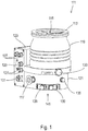
- the turbomolecular pump 111 shown comprises a pump inlet 115 surrounded by an inlet flange 113, to which a recipient (not shown) can be connected in a manner known per se.
- the gas from the recipient can be sucked out of the recipient via the pump inlet 115 and conveyed through the pump to a pump outlet 117 to which a backing pump such as a rotary vane pump may be connected.
- the inlet flange 113 forms in accordance with the orientation of the vacuum pump Fig. 1 the upper end of the housing 119 of the vacuum pump 111.
- the housing 119 comprises a lower part 121, on which an electronics housing 123 is arranged on the side. Electrical and / or electronic components of the vacuum pump 111 are accommodated in the electronics housing 123, for example for operating an electric motor 125 arranged in the vacuum pump (cf. also Fig. 3 ).
- Several connections 127 for accessories are provided on the electronics housing 123.
- a data interface 129 for example in accordance with the RS485 standard, and a power supply connection 131 are arranged on the electronics housing 123.
- turbomolecular pumps that do not have such an attached electronics housing, but are connected to an external drive electronics.
- a flood inlet 133 in particular in the form of a flood valve, is provided on the housing 119 of the turbomolecular pump 111, via which the vacuum pump 111 can be flooded.
- a sealing gas connection 135, which is also referred to as a purge gas connection via which purge gas to protect the electric motor 125 (see, for example, FIG Fig. 3 ) can be admitted into the engine compartment 137, in which the electric motor 125 is accommodated in the vacuum pump 111, before the gas conveyed by the pump.
- coolant connections 139 are also arranged in the lower part 121, one of the coolant connections being provided as an inlet and the other coolant connection being provided as an outlet for coolant, which is used for cooling purposes in the vacuum pump can be directed.
- Other existing turbomolecular vacuum pumps (not shown) are only operated with air cooling.
- the lower side 141 of the vacuum pump can serve as a standing surface, so that the vacuum pump 111 can be operated standing on the underside 141.
- the vacuum pump 111 can also be fastened to a recipient via the inlet flange 113 and can thus be operated in a manner of hanging.
- the vacuum pump 111 can be designed so that it can also be operated if it is aligned in a different way than in FIG Fig. 1 is shown.
- Embodiments of the vacuum pump can also be realized, in which the underside 141 cannot be arranged facing downwards, but turned to the side or directed upwards. Basically, any angle is possible.
- various screws 143 are also arranged, by means of which components of the vacuum pump, which are not further specified here, are fastened to one another.
- a bearing cover 145 is attached to the underside 141.
- Fastening bores 147 are also arranged on the underside 141, via which the pump 111 can be fastened, for example, to a support surface. This is not possible with other existing turbomolecular vacuum pumps (not shown), which are in particular larger than the pump shown here.
- a coolant line 148 is shown, in which the coolant introduced and discharged via the coolant connections 139 can circulate.
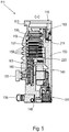
- the vacuum pump comprises a plurality of process gas pump stages for conveying the process gas present at the pump inlet 115 to the pump outlet 117.
- a rotor 149 is arranged in the housing 119 and has a rotor shaft 153 rotatable about an axis of rotation 151.
- the turbomolecular pump 111 comprises a plurality of turbomolecular pump stages connected in series with one another with effective pumping, with a plurality of radial rotor disks 155 fastened to the rotor shaft 153 and stator disks 157 arranged between the rotor disks 155 and fixed in the housing 119.
- a rotor disk 155 and an adjacent stator disk 157 each form a turbomolecular one Pump stage.
- the stator disks 157 are held at a desired axial distance from one another by spacer rings 159.
- the vacuum pump also comprises Holweck pump stages which are arranged one inside the other in the radial direction and have a pumping effect and are connected in series with one another. There are other turbomolecular vacuum pumps (not shown) that do not have Holweck pump stages.
- the rotor of the Holweck pump stages comprises a rotor hub 161 arranged on the rotor shaft 153 and two cylindrical jacket-shaped Holweck rotor sleeves 163, 165 fastened to and supported by the rotor hub 161, which are oriented coaxially to the axis of rotation 151 and nested one inside the other in the radial direction. Furthermore, two cylindrical jacket-shaped Holweck stator sleeves 167, 169 are provided, which are also oriented coaxially to the axis of rotation 151 and are nested one inside the other in the radial direction.
- the pump-active surfaces of the Holweck pump stages are formed by the lateral surfaces, that is to say by the radial inner and / or outer surfaces, of the Holweck rotor sleeves 163, 165 and of the Holweck stator sleeves 167, 169.
- the radial inner surface of the outer Holweck stator sleeve 167 lies opposite the radial outer surface of the outer Holweck rotor sleeve 163, forming a radial Holweck gap 171 and forms the first Holweck pumping stage following the turbomolecular pumps.
- the radial inner surface of the outer Holweck rotor sleeve 163 faces the radial outer surface of the inner Holweck stator sleeve 169 with the formation of a radial Holweck gap 173 and forms a second Holweck pump stage with the latter.
- the radial inner surface of the inner Holweck stator sleeve 169 lies opposite the radial outer surface of the inner Holweck rotor sleeve 165, forming a radial Holweck gap 175, and forms the third Holweck pump stage with the latter.
- a radially extending channel can be provided, via which the radially outer Holweck gap 171 is connected to the central Holweck gap 173.
- a radially extending channel can be provided at the upper end of the inner Holweck stator sleeve 169, via which the central Holweck gap 173 is connected to the radially inner Holweck gap 175.
- a connection channel 179 to the outlet 117 can also be provided.
- the aforementioned pump-active surfaces of the Holweck stator sleeves 167, 169 each have a plurality of Holweck grooves running spirally around the axis of rotation 151 in the axial direction, while the opposite ones
- the lateral surfaces of the Holweck rotor sleeves 163, 165 are smooth and drive the gas to operate the vacuum pump 111 in the Holweck grooves.
- a roller bearing 181 in the area of the pump outlet 117 and a permanent magnet bearing 183 in the area of the pump inlet 115 are provided for the rotatable mounting of the rotor shaft 153.
- a conical injection nut 185 is provided on the rotor shaft 153 with an outer diameter increasing toward the roller bearing 181.
- the spray nut 185 is in sliding contact with at least one scraper of an operating fluid reservoir.
- an injection screw can be provided instead of an injection nut. Since different designs are thus possible, the term “spray tip” is also used in this context.
- the operating medium storage comprises a plurality of absorbent disks 187 stacked one on top of the other, which are provided with an operating medium for the rolling bearing 181, e.g. are soaked with a lubricant.
- the operating medium is transferred by capillary action from the operating medium storage via the wiper to the rotating spray nut 185 and, as a result of the centrifugal force along the spray nut 185, is conveyed in the direction of the increasing outer diameter of the spray nut 185 to the roller bearing 181, where it e.g. fulfills a lubricating function.
- the roller bearing 181 and the operating fluid reservoir are enclosed in the vacuum pump by a trough-shaped insert 189 and the bearing cover 145.
- the permanent magnet bearing 183 comprises a bearing half 191 on the rotor side and a bearing half 193 on the stator side, each of which has an annular stack of a plurality of permanent magnetic rings 195 stacked on top of one another in the axial direction. Include 197.
- the ring magnets 195, 197 lie opposite one another to form a radial bearing gap 199, the rotor-side ring magnets 195 being arranged radially on the outside and the stator-side ring magnets 197 being arranged radially on the inside.
- the magnetic field present in the bearing gap 199 causes magnetic repulsive forces between the ring magnets 195, 197, which cause the rotor shaft 153 to be supported radially.
- the rotor-side ring magnets 195 are carried by a carrier section 201 of the rotor shaft 153 which surrounds the ring magnets 195 radially on the outside.
- the stator-side ring magnets 197 are carried by a stator-side support section 203 which extends through the ring magnets 197 and is suspended from radial struts 205 of the housing 119.
- Parallel to the axis of rotation 151, the rotor-side ring magnets 195 are fixed by a cover element 207 coupled to the carrier section 201.
- the stator-side ring magnets 197 are fixed parallel to the axis of rotation 151 in one direction by a fastening ring 209 connected to the carrier section 203 and a fastening ring 211 connected to the carrier section 203.
- a plate spring 213 can also be provided between the fastening ring 211 and the ring magnet 197.
- An emergency or catch bearing 215 is provided within the magnetic bearing, which runs empty without contact during normal operation of the vacuum pump 111 and only comes into engagement with an excessive radial deflection of the rotor 149 relative to the stator in order to provide a radial stop for the rotor 149 to form, so that a collision of the rotor-side structures with the stator-side structures is prevented.
- the catch bearing 215 is designed as an unlubricated roller bearing and forms a radial gap with the rotor 149 and / or the stator, which causes the catch bearing 215 to be disengaged in normal pumping operation.
- the radial deflection at which the catch bearing 215 comes into engagement is dimensioned large enough that the catch bearing 215 does not come into engagement during normal operation of the vacuum pump, and at the same time is small enough so that the collision structures on the rotor side with the structures on the stator side is prevented under all circumstances.
- the vacuum pump 111 comprises the electric motor 125 for rotatingly driving the rotor 149.
- the armature of the electric motor 125 is formed by the rotor 149, the rotor shaft 153 of which extends through the motor stator 217.
- a permanent magnet arrangement can be arranged radially on the outside or embedded on the section of the rotor shaft 153 which extends through the motor stator 217.
- the motor stator 217 is fixed in the housing within the motor space 137 provided for the electric motor 125.
- a sealing gas which is also referred to as a purge gas and which can be, for example, air or nitrogen, can enter the engine compartment 137 via the sealing gas connection 135.
- the electric motor 125 can be used before the process gas, e.g. protected against corrosive parts of the process gas.
- the engine compartment 137 can also be evacuated via the pump outlet 117, i.e. in the engine compartment 137 there is at least approximately the vacuum pressure caused by the backing pump connected to the pump outlet 117.
- a so-called and known labyrinth seal 223 can also be provided between the rotor hub 161 and a wall 221 delimiting the motor space 137, in particular in order to achieve a better seal of the motor space 217 with respect to the radially outside Holweck pump stages.
- turbomolecular vacuum pump corresponds to the conventional design of such a pump, as it is, for example, based on 1 to 5 has been described.
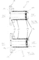
- a rotor 15 which is rotatably mounted about an axis of rotation 13 and is provided with rotor blades is provided in the region of its axial end facing the high vacuum side HV, i.e. the pump inlet 27 of the vacuum pump, with an arrangement, also referred to below as the rotor bearing package 25, of a plurality of axially successive permanent magnet rings 35.
- the rotor 15 is supported by a roller bearing (not shown) on a housing or a lower part of the pump (not shown).
- the rotor bearing package 25 is axially supported on the VV side on a support section 15b of the rotor 15 formed by a shoulder and on the HV side on an end section 15a of the rotor 15. With the end section 15a, the rings 35 are pressed together without gaps.
- stator 11 of the turbomolecular vacuum pump according to the invention is also provided with an arrangement of a plurality of axially successive permanent magnet rings 31, which is also referred to below as the stator bearing package 21.
- This stator bearing package 21 and the bearing package 25 of the rotor 15 form the radial magnetic bearing of the turbomolecular vacuum pump according to the invention for its rotor 15 and the HV-side bearing of the rotor 15 in the area of the inlet 27 of the pump.
- the stator 11 At its forevacuum-side axial end, the stator 11 is provided with an emergency bearing 23, also referred to as a safety bearing, in the form of a roller bearing, which cooperates with a pin 24 of the rotor 15 in the event of an excessive deflection of the rotor 15, which does not correspond to a normal operating state, in order to damage the Prevent magnetic bearing 21, 25.
- an emergency bearing 23 also referred to as a safety bearing, in the form of a roller bearing, which cooperates with a pin 24 of the rotor 15 in the event of an excessive deflection of the rotor 15, which does not correspond to a normal operating state, in order to damage the Prevent magnetic bearing 21, 25.
- the stator 11 is provided with a flange section 29, which serves on the one hand as an axial support section 11a for the stator bearing package 21 and on the other hand for the HV-side fixing of the stator 11 to the pump housing (not shown).
- the flange section 29 can be connected to a star-shaped end section of the pump housing (not shown), which extends perpendicular to the axis of rotation 13 in the inlet opening of the pump housing and comprises a plurality of arms which are distributed in the circumferential direction and extend in the radial direction.
- the turbomolecular vacuum pump according to the invention differs from conventional pumps of this type in that the stator bearing package 21 is axially accommodated. This is not immediate, but on the W side and HV side in each case via an adjusting section 17 or 19 on a respective support section 11b or 11a axially supported.
- an adjusting section 17 in the form of a disk spring packet is provided between the stator bearing packet 21 and the relevant support section 11b of the stator 11, the individual disk springs each being made from a bimetal.
- a non-operating state Fig. 7a the individual disc springs have a flat or only slightly curved condition.
- Fig. 7b in which due to operational warming the pump has also heated the disc springs, these have changed to a more curved state, which means that the axial height of this adjusting section 17 compared to the starting position ( Fig. 7a ) has increased.
- stator bearing package 21 When the pump heats up during operation, the stator bearing package 21 is consequently displaced in the axial direction to the HV side by the actuating section 17.
- This spring element 19 forms a further adjusting section which, together with the plate spring assembly 17, forms an actuating device according to the invention for the stator bearing assembly 21.
- This resulting direction of movement of the stator bearing package 21 corresponds to the direction in which, in the exemplary embodiment described here, the rotor 15 expands under the influence of heat and consequently the rotor bearing package 25 moves.
- FIGS 6a and 6b The geometrical relationships which result under the influence of heat, that is to say in an operating state in relation to a non-operating state, are shown in FIGS 6a and 6b shown, each showing the operational state of the vacuum pump in which the two magnetic bearing packages 21, 25 of the magnetic bearing are arranged coaxially one inside the other, the stator bearing package 21 being located radially within the rotor bearing package 25 and the pin 24 of the rotor 15 from the emergency bearing 23 Stator 11 is surrounded.
- the rotor bearing package 25 is set to the VV side.
- A denotes the axial distance between the stator 11 and the end section 15a of the rotor 15.
- D denotes the dimension by which the permanent magnet rings 31 of the stator bearing package 21 are axially offset relative to the permanent magnet rings 35 of the rotor bearing package 25.
- L finally denotes the axial height of the VV-side actuating section 17 of the stator 11, that is to say the bimetallic plate spring stack.
- the stator bearing package 21 has moved in the axial direction by the dimension x toward the HV side under the influence of heat due to the configuration according to the invention of the actuating device comprising the two adjusting sections 17, 19.
- the two adjusting sections 17, 19 have been designed such that the dimension x corresponds to the axial dimension AA - by which the rotor 15 extends in the axial direction and the rotor bearing package 25 has moved to the HV side.
- the stator bearing package 21 with the rotor 15 has "migrated" to the HV side.
- the actuating device according to the invention in particular the arrangement of spring element 19 and bimetal disc spring assembly 17, can alternatively also be assigned to rotor 15, in contrast to the exemplary embodiment described above.
- a respective assignment can be selected individually for each type of vacuum pump depending on the temperature conditions between the rotor and stator during operation.
- a rotor permanently set either in the direction of the fore-vacuum side - as in the exemplary embodiment described above - or in the direction of the high-vacuum side can lead to better running behavior.
- the respective setting of the rotor will then have to be selected accordingly. This then results in the relative arrangement of the two different adjusting sections 17, 19 of the adjusting device according to the invention.
- the "active" or “acting” actuating section for example a bimetal disc spring assembly
- the "passive” or “reacting” actuating section for example a wave spring or another Spring element
Landscapes
- Engineering & Computer Science (AREA)
- Mechanical Engineering (AREA)
- General Engineering & Computer Science (AREA)
- Physics & Mathematics (AREA)
- Electromagnetism (AREA)
- Non-Positive Displacement Air Blowers (AREA)
Priority Applications (1)
| Application Number | Priority Date | Filing Date | Title |
|---|---|---|---|
| EP19218135.2A EP3683447B1 (fr) | 2019-12-19 | 2019-12-19 | Pompe à vide |
Applications Claiming Priority (1)
| Application Number | Priority Date | Filing Date | Title |
|---|---|---|---|
| EP19218135.2A EP3683447B1 (fr) | 2019-12-19 | 2019-12-19 | Pompe à vide |
Publications (2)
| Publication Number | Publication Date |
|---|---|
| EP3683447A1 true EP3683447A1 (fr) | 2020-07-22 |
| EP3683447B1 EP3683447B1 (fr) | 2021-11-24 |
Family
ID=69410934
Family Applications (1)
| Application Number | Title | Priority Date | Filing Date |
|---|---|---|---|
| EP19218135.2A Active EP3683447B1 (fr) | 2019-12-19 | 2019-12-19 | Pompe à vide |
Country Status (1)
| Country | Link |
|---|---|
| EP (1) | EP3683447B1 (fr) |
Cited By (1)
| Publication number | Priority date | Publication date | Assignee | Title |
|---|---|---|---|---|
| EP4108930A1 (fr) * | 2022-08-31 | 2022-12-28 | Pfeiffer Vacuum Technology AG | Pompe à vide dotée d'un support d'aimants réglable dans une direction axiale |
Citations (3)
| Publication number | Priority date | Publication date | Assignee | Title |
|---|---|---|---|---|
| DE102009024337A1 (de) * | 2009-06-09 | 2010-12-16 | Oerlikon Leybold Vacuum Gmbh | Vakuumpumpe |
| EP3085964A1 (fr) * | 2015-04-21 | 2016-10-26 | Pfeiffer Vacuum Gmbh | Production d'un composant de pompe à vide par fabrication additive métallique |
| EP3444478A1 (fr) * | 2017-08-18 | 2019-02-20 | Pfeiffer Vacuum Gmbh | Pompe à vide |
-
2019
- 2019-12-19 EP EP19218135.2A patent/EP3683447B1/fr active Active
Patent Citations (3)
| Publication number | Priority date | Publication date | Assignee | Title |
|---|---|---|---|---|
| DE102009024337A1 (de) * | 2009-06-09 | 2010-12-16 | Oerlikon Leybold Vacuum Gmbh | Vakuumpumpe |
| EP3085964A1 (fr) * | 2015-04-21 | 2016-10-26 | Pfeiffer Vacuum Gmbh | Production d'un composant de pompe à vide par fabrication additive métallique |
| EP3444478A1 (fr) * | 2017-08-18 | 2019-02-20 | Pfeiffer Vacuum Gmbh | Pompe à vide |
Cited By (1)
| Publication number | Priority date | Publication date | Assignee | Title |
|---|---|---|---|---|
| EP4108930A1 (fr) * | 2022-08-31 | 2022-12-28 | Pfeiffer Vacuum Technology AG | Pompe à vide dotée d'un support d'aimants réglable dans une direction axiale |
Also Published As
| Publication number | Publication date |
|---|---|
| EP3683447B1 (fr) | 2021-11-24 |
Similar Documents
| Publication | Publication Date | Title |
|---|---|---|
| EP3657021B1 (fr) | Pompe à vide | |
| EP3683447B1 (fr) | Pompe à vide | |
| DE60319585T2 (de) | Vakuumpumpe | |
| EP4212730A1 (fr) | Pompe à vide avec étage de pompage de holward optimisé pour compenser la perte de performance liée à la température | |
| EP3196471B1 (fr) | Pompe a vide | |
| EP4108932A1 (fr) | Reciate et pompe à vide élevé | |
| EP3693610B1 (fr) | Pompe à vide moléculaire | |
| EP3734078B1 (fr) | Pompe turbomoléculaire et procédé de fabrication d'un disque de stator pour une telle pompe | |
| DE102020131948B3 (de) | Festplattenlaufwerk | |
| EP3730802B1 (fr) | Élément de bride | |
| EP3670924B1 (fr) | Pompe à vide et procédé de fabrication d'une telle pompe à vide | |
| EP3561307B1 (fr) | Pompe à vide avec une bride de port d'aspiration et un support de palier dans le port d'aspiration | |
| EP3628883B1 (fr) | Pompe à vide | |
| DE102019214279A1 (de) | Seitenkanalverdichter für ein Brennstoffzellensystem zur Förderung und/oder Verdichtung eines gasförmigen Mediums | |
| EP3135932B1 (fr) | Pompe à vide et palier à aimant permanent | |
| EP3267040B1 (fr) | Pompe turbomoléculaire | |
| EP3318763B1 (fr) | Étanchéité au vide, étanchéité double, système à vide et pompe à vide | |
| EP3760872B1 (fr) | Pompe à vide pourvue d'un agencement de fixation destiné à l'application de la pompe à une structure de fixation ainsi qu'un poste de pompage doté d'une telle pompe à vide montée sur celui-ci | |
| EP3575610A1 (fr) | Pompe à vide avec réservoir de lubrifiant | |
| EP3907406B1 (fr) | Pompe à vide | |
| EP3096020B1 (fr) | Pompe à vide | |
| EP4108930A1 (fr) | Pompe à vide dotée d'un support d'aimants réglable dans une direction axiale | |
| EP3767109B1 (fr) | Système à vide | |
| EP3597926B1 (fr) | Pompe à vide | |
| EP3640481B1 (fr) | Pompe à vide |
Legal Events
| Date | Code | Title | Description |
|---|---|---|---|
| PUAI | Public reference made under article 153(3) epc to a published international application that has entered the european phase |
Free format text: ORIGINAL CODE: 0009012 |
|
| STAA | Information on the status of an ep patent application or granted ep patent |
Free format text: STATUS: THE APPLICATION HAS BEEN PUBLISHED |
|
| AK | Designated contracting states |
Kind code of ref document: A1 Designated state(s): AL AT BE BG CH CY CZ DE DK EE ES FI FR GB GR HR HU IE IS IT LI LT LU LV MC MK MT NL NO PL PT RO RS SE SI SK SM TR |
|
| AX | Request for extension of the european patent |
Extension state: BA ME |
|
| STAA | Information on the status of an ep patent application or granted ep patent |
Free format text: STATUS: REQUEST FOR EXAMINATION WAS MADE |
|
| 17P | Request for examination filed |
Effective date: 20200812 |
|
| RBV | Designated contracting states (corrected) |
Designated state(s): AL AT BE BG CH CY CZ DE DK EE ES FI FR GB GR HR HU IE IS IT LI LT LU LV MC MK MT NL NO PL PT RO RS SE SI SK SM TR |
|
| GRAP | Despatch of communication of intention to grant a patent |
Free format text: ORIGINAL CODE: EPIDOSNIGR1 |
|
| STAA | Information on the status of an ep patent application or granted ep patent |
Free format text: STATUS: GRANT OF PATENT IS INTENDED |
|
| INTG | Intention to grant announced |
Effective date: 20210707 |
|
| GRAS | Grant fee paid |
Free format text: ORIGINAL CODE: EPIDOSNIGR3 |
|
| GRAA | (expected) grant |
Free format text: ORIGINAL CODE: 0009210 |
|
| STAA | Information on the status of an ep patent application or granted ep patent |
Free format text: STATUS: THE PATENT HAS BEEN GRANTED |
|
| AK | Designated contracting states |
Kind code of ref document: B1 Designated state(s): AL AT BE BG CH CY CZ DE DK EE ES FI FR GB GR HR HU IE IS IT LI LT LU LV MC MK MT NL NO PL PT RO RS SE SI SK SM TR |
|
| REG | Reference to a national code |
Ref country code: GB Ref legal event code: FG4D Free format text: NOT ENGLISH |
|
| REG | Reference to a national code |
Ref country code: AT Ref legal event code: REF Ref document number: 1450070 Country of ref document: AT Kind code of ref document: T Effective date: 20211215 |
|
| REG | Reference to a national code |
Ref country code: DE Ref legal event code: R096 Ref document number: 502019002841 Country of ref document: DE |
|
| REG | Reference to a national code |
Ref country code: IE Ref legal event code: FG4D Free format text: LANGUAGE OF EP DOCUMENT: GERMAN |
|
| REG | Reference to a national code |
Ref country code: LT Ref legal event code: MG9D |
|
| REG | Reference to a national code |
Ref country code: NL Ref legal event code: MP Effective date: 20211124 |
|
| PG25 | Lapsed in a contracting state [announced via postgrant information from national office to epo] |
Ref country code: RS Free format text: LAPSE BECAUSE OF FAILURE TO SUBMIT A TRANSLATION OF THE DESCRIPTION OR TO PAY THE FEE WITHIN THE PRESCRIBED TIME-LIMIT Effective date: 20211124 Ref country code: LT Free format text: LAPSE BECAUSE OF FAILURE TO SUBMIT A TRANSLATION OF THE DESCRIPTION OR TO PAY THE FEE WITHIN THE PRESCRIBED TIME-LIMIT Effective date: 20211124 Ref country code: FI Free format text: LAPSE BECAUSE OF FAILURE TO SUBMIT A TRANSLATION OF THE DESCRIPTION OR TO PAY THE FEE WITHIN THE PRESCRIBED TIME-LIMIT Effective date: 20211124 Ref country code: BG Free format text: LAPSE BECAUSE OF FAILURE TO SUBMIT A TRANSLATION OF THE DESCRIPTION OR TO PAY THE FEE WITHIN THE PRESCRIBED TIME-LIMIT Effective date: 20220224 |
|
| PG25 | Lapsed in a contracting state [announced via postgrant information from national office to epo] |
Ref country code: IS Free format text: LAPSE BECAUSE OF FAILURE TO SUBMIT A TRANSLATION OF THE DESCRIPTION OR TO PAY THE FEE WITHIN THE PRESCRIBED TIME-LIMIT Effective date: 20220324 Ref country code: SE Free format text: LAPSE BECAUSE OF FAILURE TO SUBMIT A TRANSLATION OF THE DESCRIPTION OR TO PAY THE FEE WITHIN THE PRESCRIBED TIME-LIMIT Effective date: 20211124 Ref country code: PT Free format text: LAPSE BECAUSE OF FAILURE TO SUBMIT A TRANSLATION OF THE DESCRIPTION OR TO PAY THE FEE WITHIN THE PRESCRIBED TIME-LIMIT Effective date: 20220324 Ref country code: PL Free format text: LAPSE BECAUSE OF FAILURE TO SUBMIT A TRANSLATION OF THE DESCRIPTION OR TO PAY THE FEE WITHIN THE PRESCRIBED TIME-LIMIT Effective date: 20211124 Ref country code: NO Free format text: LAPSE BECAUSE OF FAILURE TO SUBMIT A TRANSLATION OF THE DESCRIPTION OR TO PAY THE FEE WITHIN THE PRESCRIBED TIME-LIMIT Effective date: 20220224 Ref country code: NL Free format text: LAPSE BECAUSE OF FAILURE TO SUBMIT A TRANSLATION OF THE DESCRIPTION OR TO PAY THE FEE WITHIN THE PRESCRIBED TIME-LIMIT Effective date: 20211124 Ref country code: LV Free format text: LAPSE BECAUSE OF FAILURE TO SUBMIT A TRANSLATION OF THE DESCRIPTION OR TO PAY THE FEE WITHIN THE PRESCRIBED TIME-LIMIT Effective date: 20211124 Ref country code: HR Free format text: LAPSE BECAUSE OF FAILURE TO SUBMIT A TRANSLATION OF THE DESCRIPTION OR TO PAY THE FEE WITHIN THE PRESCRIBED TIME-LIMIT Effective date: 20211124 Ref country code: GR Free format text: LAPSE BECAUSE OF FAILURE TO SUBMIT A TRANSLATION OF THE DESCRIPTION OR TO PAY THE FEE WITHIN THE PRESCRIBED TIME-LIMIT Effective date: 20220225 Ref country code: ES Free format text: LAPSE BECAUSE OF FAILURE TO SUBMIT A TRANSLATION OF THE DESCRIPTION OR TO PAY THE FEE WITHIN THE PRESCRIBED TIME-LIMIT Effective date: 20211124 |
|
| PG25 | Lapsed in a contracting state [announced via postgrant information from national office to epo] |
Ref country code: SM Free format text: LAPSE BECAUSE OF FAILURE TO SUBMIT A TRANSLATION OF THE DESCRIPTION OR TO PAY THE FEE WITHIN THE PRESCRIBED TIME-LIMIT Effective date: 20211124 Ref country code: SK Free format text: LAPSE BECAUSE OF FAILURE TO SUBMIT A TRANSLATION OF THE DESCRIPTION OR TO PAY THE FEE WITHIN THE PRESCRIBED TIME-LIMIT Effective date: 20211124 Ref country code: RO Free format text: LAPSE BECAUSE OF FAILURE TO SUBMIT A TRANSLATION OF THE DESCRIPTION OR TO PAY THE FEE WITHIN THE PRESCRIBED TIME-LIMIT Effective date: 20211124 Ref country code: EE Free format text: LAPSE BECAUSE OF FAILURE TO SUBMIT A TRANSLATION OF THE DESCRIPTION OR TO PAY THE FEE WITHIN THE PRESCRIBED TIME-LIMIT Effective date: 20211124 Ref country code: DK Free format text: LAPSE BECAUSE OF FAILURE TO SUBMIT A TRANSLATION OF THE DESCRIPTION OR TO PAY THE FEE WITHIN THE PRESCRIBED TIME-LIMIT Effective date: 20211124 |
|
| REG | Reference to a national code |
Ref country code: DE Ref legal event code: R097 Ref document number: 502019002841 Country of ref document: DE |
|
| PG25 | Lapsed in a contracting state [announced via postgrant information from national office to epo] |
Ref country code: MC Free format text: LAPSE BECAUSE OF FAILURE TO SUBMIT A TRANSLATION OF THE DESCRIPTION OR TO PAY THE FEE WITHIN THE PRESCRIBED TIME-LIMIT Effective date: 20211124 |
|
| REG | Reference to a national code |
Ref country code: BE Ref legal event code: MM Effective date: 20211231 |
|
| PLBE | No opposition filed within time limit |
Free format text: ORIGINAL CODE: 0009261 |
|
| STAA | Information on the status of an ep patent application or granted ep patent |
Free format text: STATUS: NO OPPOSITION FILED WITHIN TIME LIMIT |
|
| PG25 | Lapsed in a contracting state [announced via postgrant information from national office to epo] |
Ref country code: LU Free format text: LAPSE BECAUSE OF NON-PAYMENT OF DUE FEES Effective date: 20211219 Ref country code: IE Free format text: LAPSE BECAUSE OF NON-PAYMENT OF DUE FEES Effective date: 20211219 Ref country code: AL Free format text: LAPSE BECAUSE OF FAILURE TO SUBMIT A TRANSLATION OF THE DESCRIPTION OR TO PAY THE FEE WITHIN THE PRESCRIBED TIME-LIMIT Effective date: 20211124 |
|
| 26N | No opposition filed |
Effective date: 20220825 |
|
| PG25 | Lapsed in a contracting state [announced via postgrant information from national office to epo] |
Ref country code: SI Free format text: LAPSE BECAUSE OF FAILURE TO SUBMIT A TRANSLATION OF THE DESCRIPTION OR TO PAY THE FEE WITHIN THE PRESCRIBED TIME-LIMIT Effective date: 20211124 Ref country code: FR Free format text: LAPSE BECAUSE OF NON-PAYMENT OF DUE FEES Effective date: 20220124 Ref country code: BE Free format text: LAPSE BECAUSE OF NON-PAYMENT OF DUE FEES Effective date: 20211231 |
|
| PG25 | Lapsed in a contracting state [announced via postgrant information from national office to epo] |
Ref country code: CY Free format text: LAPSE BECAUSE OF FAILURE TO SUBMIT A TRANSLATION OF THE DESCRIPTION OR TO PAY THE FEE WITHIN THE PRESCRIBED TIME-LIMIT Effective date: 20211124 |
|
| PG25 | Lapsed in a contracting state [announced via postgrant information from national office to epo] |
Ref country code: HU Free format text: LAPSE BECAUSE OF FAILURE TO SUBMIT A TRANSLATION OF THE DESCRIPTION OR TO PAY THE FEE WITHIN THE PRESCRIBED TIME-LIMIT; INVALID AB INITIO Effective date: 20191219 |
|
| REG | Reference to a national code |
Ref country code: CH Ref legal event code: PL |
|
| PG25 | Lapsed in a contracting state [announced via postgrant information from national office to epo] |
Ref country code: LI Free format text: LAPSE BECAUSE OF NON-PAYMENT OF DUE FEES Effective date: 20221231 Ref country code: CH Free format text: LAPSE BECAUSE OF NON-PAYMENT OF DUE FEES Effective date: 20221231 |
|
| PGFP | Annual fee paid to national office [announced via postgrant information from national office to epo] |
Ref country code: GB Payment date: 20231220 Year of fee payment: 5 |
|
| PGFP | Annual fee paid to national office [announced via postgrant information from national office to epo] |
Ref country code: IT Payment date: 20231228 Year of fee payment: 5 Ref country code: CZ Payment date: 20231212 Year of fee payment: 5 |
|
| PG25 | Lapsed in a contracting state [announced via postgrant information from national office to epo] |
Ref country code: MK Free format text: LAPSE BECAUSE OF FAILURE TO SUBMIT A TRANSLATION OF THE DESCRIPTION OR TO PAY THE FEE WITHIN THE PRESCRIBED TIME-LIMIT Effective date: 20211124 |
|
| PGFP | Annual fee paid to national office [announced via postgrant information from national office to epo] |
Ref country code: DE Payment date: 20240227 Year of fee payment: 5 |