EP4108553A1 - Instrumententafelträger für ein kraftfahrzeug und eine instrumententafelträgeranordnung sowie ein verfahren zu deren herstellung - Google Patents
Instrumententafelträger für ein kraftfahrzeug und eine instrumententafelträgeranordnung sowie ein verfahren zu deren herstellung Download PDFInfo
- Publication number
- EP4108553A1 EP4108553A1 EP21183722.4A EP21183722A EP4108553A1 EP 4108553 A1 EP4108553 A1 EP 4108553A1 EP 21183722 A EP21183722 A EP 21183722A EP 4108553 A1 EP4108553 A1 EP 4108553A1
- Authority
- EP
- European Patent Office
- Prior art keywords
- instrument panel
- panel support
- cross member
- head
- display
- Prior art date
- Legal status (The legal status is an assumption and is not a legal conclusion. Google has not performed a legal analysis and makes no representation as to the accuracy of the status listed.)
- Granted
Links
Images






Classifications
-
- B—PERFORMING OPERATIONS; TRANSPORTING
- B23—MACHINE TOOLS; METAL-WORKING NOT OTHERWISE PROVIDED FOR
- B23K—SOLDERING OR UNSOLDERING; WELDING; CLADDING OR PLATING BY SOLDERING OR WELDING; CUTTING BY APPLYING HEAT LOCALLY, e.g. FLAME CUTTING; WORKING BY LASER BEAM
- B23K31/00—Processes relevant to this subclass, specially adapted for particular articles or purposes, but not covered by any single one of main groups B23K1/00 - B23K28/00
- B23K31/02—Processes relevant to this subclass, specially adapted for particular articles or purposes, but not covered by any single one of main groups B23K1/00 - B23K28/00 relating to soldering or welding
-
- B—PERFORMING OPERATIONS; TRANSPORTING
- B62—LAND VEHICLES FOR TRAVELLING OTHERWISE THAN ON RAILS
- B62D—MOTOR VEHICLES; TRAILERS
- B62D25/00—Superstructure or monocoque structure sub-units; Parts or details thereof not otherwise provided for
- B62D25/08—Front or rear portions
- B62D25/14—Dashboards as superstructure sub-units
- B62D25/145—Dashboards as superstructure sub-units having a crossbeam incorporated therein
-
- B—PERFORMING OPERATIONS; TRANSPORTING
- B60—VEHICLES IN GENERAL
- B60K—ARRANGEMENT OR MOUNTING OF PROPULSION UNITS OR OF TRANSMISSIONS IN VEHICLES; ARRANGEMENT OR MOUNTING OF PLURAL DIVERSE PRIME-MOVERS IN VEHICLES; AUXILIARY DRIVES FOR VEHICLES; INSTRUMENTATION OR DASHBOARDS FOR VEHICLES; ARRANGEMENTS IN CONNECTION WITH COOLING, AIR INTAKE, GAS EXHAUST OR FUEL SUPPLY OF PROPULSION UNITS IN VEHICLES
- B60K37/00—Dashboards
-
- B—PERFORMING OPERATIONS; TRANSPORTING
- B23—MACHINE TOOLS; METAL-WORKING NOT OTHERWISE PROVIDED FOR
- B23K—SOLDERING OR UNSOLDERING; WELDING; CLADDING OR PLATING BY SOLDERING OR WELDING; CUTTING BY APPLYING HEAT LOCALLY, e.g. FLAME CUTTING; WORKING BY LASER BEAM
- B23K37/00—Auxiliary devices or processes, not specially adapted for a procedure covered by only one of the other main groups of this subclass
- B23K37/04—Auxiliary devices or processes, not specially adapted for a procedure covered by only one of the other main groups of this subclass for holding or positioning work
- B23K37/0426—Fixtures for other work
- B23K37/0435—Clamps
- B23K37/0443—Jigs
-
- B—PERFORMING OPERATIONS; TRANSPORTING
- B62—LAND VEHICLES FOR TRAVELLING OTHERWISE THAN ON RAILS
- B62D—MOTOR VEHICLES; TRAILERS
- B62D65/00—Designing, manufacturing, e.g. assembling, facilitating disassembly, or structurally modifying motor vehicles or trailers, not otherwise provided for
- B62D65/02—Joining sub-units or components to, or positioning sub-units or components with respect to, body shell or other sub-units or components
- B62D65/024—Positioning of sub-units or components with respect to body shell or other sub-units or components
-
- B—PERFORMING OPERATIONS; TRANSPORTING
- B62—LAND VEHICLES FOR TRAVELLING OTHERWISE THAN ON RAILS
- B62D—MOTOR VEHICLES; TRAILERS
- B62D65/00—Designing, manufacturing, e.g. assembling, facilitating disassembly, or structurally modifying motor vehicles or trailers, not otherwise provided for
- B62D65/02—Joining sub-units or components to, or positioning sub-units or components with respect to, body shell or other sub-units or components
- B62D65/14—Joining sub-units or components to, or positioning sub-units or components with respect to, body shell or other sub-units or components the sub-units or components being passenger compartment fittings, e.g. seats, linings, trim, instrument panels
-
- B—PERFORMING OPERATIONS; TRANSPORTING
- B60—VEHICLES IN GENERAL
- B60K—ARRANGEMENT OR MOUNTING OF PROPULSION UNITS OR OF TRANSMISSIONS IN VEHICLES; ARRANGEMENT OR MOUNTING OF PLURAL DIVERSE PRIME-MOVERS IN VEHICLES; AUXILIARY DRIVES FOR VEHICLES; INSTRUMENTATION OR DASHBOARDS FOR VEHICLES; ARRANGEMENTS IN CONNECTION WITH COOLING, AIR INTAKE, GAS EXHAUST OR FUEL SUPPLY OF PROPULSION UNITS IN VEHICLES
- B60K2360/00—Indexing scheme associated with groups B60K35/00 or B60K37/00 relating to details of instruments or dashboards
- B60K2360/816—Fastening of displays or touch screens
Definitions
- the invention relates to an instrument panel support for a motor vehicle, which has a cross member that can be integrated between the A-pillars of a motor vehicle body and an instrument panel support arrangement, as well as a method for the production thereof.
- Instrument panel supports are used in motor vehicles as a supporting component for various cockpit functions.
- One of the main components of an instrument panel support is the cross member.
- the cross member is part of the motor vehicle body and extends essentially horizontally in the area below the windshield, transversely between the A pillars.
- the cross member has a driver side length and a passenger side length and is typically secured against the bulkhead, i.e. the partition between the engine compartment and the vehicle interior, as well as additional support against the vehicle floor.
- the cross member has a stiffening function within the vehicle body and is used to attach and stiffen the instrument panel.
- various mounts are provided on the cross member, to which different vehicle functional components such as the longitudinal pillar, heating and air conditioning system, center console and/or a head-up display (HUD) are attached.
- vehicle functional components such as the longitudinal pillar, heating and air conditioning system, center console and/or a head-up display (HUD) are attached.
- HUD head-up display
- a head-up display is a display system or device that projects information into a user's field of vision.
- the present invention relates to an instrument panel support with a cross member, which has a mount for fixing a head-up display.
- the DE 10 2005 031 357 B4 discloses a motor vehicle and an instrument panel module for use in the motor vehicle having a cross member.
- the cross member has a fastening device for connecting a head-up display or its projection device.
- a method for mounting a head-up display to a module cross member for a dashboard is disclosed in the DE 10 2017 007 470 B3 .
- the DE 10 2006 025 386 A1 includes a vehicle cockpit with a head-up display and a cross member of the prior art, in which fastening means are provided for pre-assembly of the head-up display on the cross member and for final assembly on another supporting body part.
- the fastening means have a holder for accommodating the head-up display and for fastening it to the cross member.
- the installation position and the clear positioning of the head-up display in the vehicle within the dashboard or the instrument panel support arrangement is of essential importance in order to meet the required quality characteristics, in particular the functional dimensions and the to comply with the footing plan. Accordingly, the screwing or mounting surfaces of the head-up display must be very precise. In particular, the screwing or mounting surfaces of the head-up display must have an exact position in the z-axis in the reference point system of an instrument panel support. Furthermore, the tilt angle of the head-up display around the y-axis is of great importance in order to meet the functional requirements. In addition, an instrument panel support and the instrument panel support arrangement with an integrated head-up display must meet necessary safety regulations, in particular electrotechnical safety regulations.
- the invention is based on the object of creating an instrument panel support with a holder for a head-up display on the cross member which is improved in terms of function and assembly technology, and of demonstrating an instrument panel support arrangement and a method for producing it.
- the solution to this problem consists in an instrument panel support according to claim 1.
- An instrument panel support arrangement with an instrument panel support according to the invention is the subject of claim 17.
- Claim 18 discloses a method of manufacturing an instrument panel support assembly.
- the instrument panel cross member for a motor vehicle has a cross member that can be integrated between the A pillars of a motor vehicle body and fixed to the A pillars.
- a mount for a head-up display (HUD) is arranged on the cross member.
- the holder has a support body for the head-up display, the support body being fixed to the cross member via supports.
- the supporting body has flange sections with mounting openings for Attachment of the head-up display.
- An electrically non-conductive coupling element is provided in the area of a mounting opening.
- the electrically non-conductive coupling element is associated with the assembly openings in a non-positive and/or positive manner.
- the electrically non-conductive coupling element(s) are designed and configured in terms of material and configuration to ensure electrical isolation between a head-up display mounted on or in the support body and the metallic components of the instrument panel support within the instrument panel support arrangement.
- Non-conductive or non-conductive means that the coupling links consist in particular of a non-conductive material or consist of substances that are classified in the non-conductive category in terms of conductivity. It is essential that the non-conductive coupling links ensure galvanic isolation between the supporting body and a mounted head-up display.
- the head-up display or the housing of the head-up display should not be part of the body's electrical ground. This requirement is met by the electrically non-conductive coupling links, which cause galvanic isolation between the supporting body and the head-up display.
- the bracket includes the supporting body for the head-up display which is fixed to supports.
- the supporting body is welded between two lateral supports.
- the supports are welded to the crossbeam in a materially bonded manner.
- the configuration makes it possible to set and fix the bracket in the correct position during welding in the z-axis (vehicle vertical axis). In this way, deviations in shape or tolerances of the cross member in the z-axis can also be compensated.
- the holder can be set up and joined in the correct position by rotating or tilting about the y-axis. Overall, tighter tolerances can be achieved, specifically with a rational welding process for joining the components of the crossbeam and attitude, as well as their supports and support bodies to one another.
- the cross member In order to do justice to its function in the instrument panel support and within the instrument panel support arrangement, the cross member is equipped with various holder components. These are metallic holder components that are welded to the cross member. Through this Technical welding processes lead to a distortion of the cross member and the relative position of assembly points for the various functional components, in particular the holder for the head-up display. Such a welding distortion as well as unavoidable tolerances in the joining process are compensated for when positioning the support body relative to the supports. The side walls of the support body rest against the respective adjacent inner sides of the supports and are joined to the supports by welding.
- the correct position of the support body is set within the holder, so that when a head-up display is later installed, the position of the head-up display does not have to be adjusted during or after installation.
- a preferred aspect of the invention is that the holder and in particular its supporting body is aligned in the correct position relative to the supports, in particular in the z-x plane and in this end position there is a material connection between the supporting body and the supports.
- the supports have contact surfaces or joining surfaces on lateral legs, which contact the side walls of the supporting body on the outside.
- the support body is welded to the supports in the area of the contact surfaces.
- the supporting body is provided with the electrically non-conductive coupling elements provided on the mounting flanges in the area of the mounting opening and joined to the supports.
- the supports themselves are advantageously fixed by welding to the crossbeam before the supporting body is joined.
- a preferred embodiment provides that the holder is joined between two supports.
- a support preferably has a support base that is configured to match the outer contour of the cross member.
- the support foot encompasses the crossbeam in areas and is joined to the crossbeam in a materially bonded manner, in particular welded.
- a support is preferably configured in a U-shape in horizontal cross-section, in particular in the support foot, with a web and two legs.
- Two supports are arranged at an axial distance from one another in the longitudinal direction (y-axis) of the cross member.
- the webs of each support run in the x-axis.
- the thigh the struts are directed from the web towards the supporting body.
- the supporting body is accommodated between the supports.
- a support has contact surfaces for the supporting body. These are preferably provided on the leg, in particular on the end faces of the legs.
- the support body rests with its side walls on the contact surfaces and is joined in a material-to-material manner.
- An advantageous embodiment of the instrument panel support according to the invention provides that a positioning element for the head-up display is provided adjacent to at least one assembly opening.
- a locator serves as an assembly aid and to facilitate installation and alignment of the head-up display in the bracket and instrument panel support assembly.
- a positioning element is preferably configured as an opening or hole, in particular a slot, adjacent to an assembly opening.
- the positioning element is advantageously formed on or within the area of an electrically non-conductive coupling element.
- a positioning aid in the form of a hole is used to accommodate a pin provided on the head-up display, which can be used to align the head-up display during assembly.
- a flange portion is provided at the upper end of a side wall.
- the flange portions face outward (y-axis) from the sidewall.
- An embodiment which is particularly advantageous in practice provides that at least one flange section of a supporting body has two mounting openings which are arranged at a distance from one another in the x-axis (longitudinal axis of the vehicle).
- a positioning element, in particular a hole, is provided adjacent to one of the two mounting openings in a flange section.
- An electrically non-conductive coupling element is preferably made of plastic.
- the coupling element can at least partially cover a flange section on the top and/or bottom. Furthermore, the coupling element can cover the mounting opening on the inside. In this case, the inner peripheral wall of the mounting opening is covered by the material of the coupling element or is coated with the material of the coupling element.
- a further embodiment provides that a screw connection element is integrated in the coupling element.
- a screw connection element can be made from the material of the coupling element itself or can be formed by a separate component.
- a screw connection element is in particular a threaded nut or threaded sleeve into which a mounting screw for mounting a head-up display can be screwed.
- the coupling member preferably has a socket body.
- the socket body is provided in particular as a continuation of a mounting opening on the underside of a coupling link or the underside of a flange section.
- the nozzle body and the mounting hole have a common central axis.
- a screw connection element integrated into the coupling element is arranged in particular in the socket body and serves as an abutment for a mounting screw.
- the coupling element is designed in the form of a clip.
- a coupling link clip is placed laterally on a flange section and clasps the area of a mounting opening on the top and bottom.
- a coupling member clip is automatically spring clamped to a flange section.
- a coupling member clip can have latching elements, for example spring legs provided with latching lugs, which press together with mating surfaces on the mounting flange or pass through openings on a mounting flange. Through-openings congruent to a mounting opening are provided in the coupling element clip. The same applies to a positioning element in the form of a hole.
- a link clip has an aperture that aligns with the positioning hole.
- this is designed as an injection molded part.
- the area around an assembly opening in the flange section is overmoulded with an electrically non-conductive material, in particular plastic.
- Positioning elements adjacent to a mounting opening, in particular a positioning hole, are also overmoulded.
- a coupling element can be designed as a plastic clip with an integrated threaded insert or as a plastic encapsulation with a threaded insert.
- Threaded insert is in particular a screw nut into which a mounting screw for mounting and fixing a head-up display can be screwed.
- a mounting screw of or for the head-up display that fits the threaded insert or the screw nut can be designed with an electrically insulating coating and/or only be in electrically isolated contact with the head-up display.
- the configuration according to the invention makes it possible to adjust the holder when it is joined to the supports, in particular in the z-direction. In this way, deviations in shape of the cross member, in particular in the z-direction, can be compensated for. In addition, tilting about the y-axis can advantageously be compensated for and the correct position of the holder can be set. Overall, the invention ensures that tighter tolerances can be achieved, with the production being carried out by means of a cohesive standard process by means of welding. As a result, cycle times can be increased and production can be carried out more efficiently overall.
- the supporting body has two side walls arranged axially at a distance in the longitudinal direction (y-axis) of the cross member.
- the side walls are oriented in the longitudinal axis of the vehicle (x-axis) and extend transversely to the longitudinal direction of the cross member.
- longitudinal walls in particular a rear wall or longitudinal wall struts, and/or a floor or floor sections or floor struts extend between the side walls in the longitudinal direction of the supporting body, ie in the y-axis.
- the supporting body provides an accommodation space in which a head-up display can be accommodated in a protected manner.
- the receiving body is delimited by the side walls and at least one longitudinal wall, in particular a rear wall, as well as longitudinal wall struts and/or bottom struts.
- the side walls are rigidly connected to one another. This takes place via at least one longitudinal wall and longitudinal wall struts and/or bottom struts. This enables a head-up display to be accommodated and held in a particularly advantageous manner.
- the supporting body can be open at the front or rear, in particular at the front. This improves the mountability of a head-up display and its Accessibility.
- the supporting body can have front and/or rear longitudinal walls between the side walls, which have a lower height than the side walls.
- a rear wall which is less high in the z-axis than the side walls extends between the rear ends of the side walls.
- the trough-shaped supporting body is essentially open at the front.
- a longitudinal wall strut extends along the floor between the side walls, which is designed as a changeover on the floor.
- a support is joined on the outside in each case to a side wall of the supporting body in a materially bonded manner.
- Positioning and/or joining aids can be provided on the side walls and/or the supports, for example in the form of markers. Markers can be formed by material embossing, material changes, beads and/or openings or holes.
- a joint area between the supports and the side walls of the supporting body extends within a z-x plane.
- the contact surfaces in particular on the legs of a support, can form a common joining area. It is also possible that the contact surfaces and thus the joining surfaces are offset in the z-x plane. This can be done, for example, by a different leg length.
- the legs can also be configured in such a way that contact surfaces and thus joining surfaces are present in positions that are three-dimensionally shifted relative to one another.
- the supporting body has a bottom.
- the support body is preferably designed to be open at the bottom in some areas. This measure contributes to reducing the weight of the bracket.
- the supporting body has a base with a receptacle and/or passages and/or openings, it being possible for an opening to have a collar running all the way around the edge or collar sections on the edge.
- An instrument panel support assembly includes an instrument panel support of the present invention and a head-up display mounted on the bracket.
- the support body is aligned in the correct position relative to the supports already joined to the cross member in the z-axis (vertical vehicle axis) and in the x-axis (longitudinal vehicle axis), i.e. in the z-x plane, and then welded to the supports with a material bond .
- This is done with a suitable welding device or welding gauge. After welding the components, the bracket is ready to hold the head-up display. Subsequent adjustment of the head-up display itself is no longer necessary.
- an embodiment that improves the functionality of an instrument panel support provides that the cross member has a driver-side longitudinal section with a cross member end, the cross member end having an assembly opening that penetrates the driver-side longitudinal section or the driver-side longitudinal section in the area of the cross member end in the vehicle longitudinal axis (x-axis).
- the cross-sectional geometry together with the fixing of the cross member in the vehicle longitudinal axis (x-axis) ensures an advantageous assembly and a fixing of the instrument panel support within a motor vehicle body that is advantageous in terms of static and dynamic load behavior.
- the end of the cross member has a rectangular cross-section in vertical cross-section Configuration with a height measured in the vehicle vertical axis (z-axis) that is greater than the width measured in the vehicle longitudinal axis (x-axis).
- Terms such as top and bottom, front and rear, horizontal and vertical or longitudinal and transverse, and top and bottom, driver's side, driver's side, passenger's side or passenger's side refer to the installation position of the cross member between the A-pillars within a motor vehicle body or the installation position of the bracket on Cross member and relative to the cross member.
- a vehicle coordinate system is a three-dimensional Cartesian coordinate system to characterize the axles within a motor vehicle.
- the origin of the coordinate system lies in the center plane of the vehicle.
- the x-axis corresponds to the longitudinal axis of the vehicle, the y-axis to the transverse axis of the vehicle and the z-axis to the vertical axis of the vehicle.
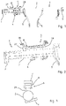
- figure 1 shows an instrument panel support 1.
- figure 2 shows the driver-side longitudinal section of the instrument panel support 1 as shown in FIG figure 1 in an enlarged view.
- figure 3 shows a technically schematic and greatly simplified side view of an instrument panel support 1.
- the instrument panel support 1 has a cross member 2 .
- the cross member 2 can be integrated between A-pillars (not shown here) of a motor vehicle body and extends essentially horizontally in the vehicle's transverse axis (y-axis) transversely between the A-pillars.
- the cross member 2 is fixed to the A-pillars via assembly components 3 provided at the end of the cross member 2.
- the cross member 2 is made of steel. Various holders for vehicle function components are attached to the cross member 2 .
- a handlebar holder 4 and support struts 5 are designated as examples.
- the cross member 2 has a mount 6 for a head-up display 7 (HUD).
- HUD head-up display 7
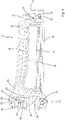
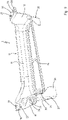
- FIGS. 4 to 7 show a first embodiment of a holder 6.
- a holder 6 includes a supporting body 8 for a head-up display 7.
- the supporting body 8 is preferably configured in the form of a trough.
- the supporting body 8 has two side walls 9, 10 which are arranged at a distance from one another in the y-axis.
- a closed rear wall 11 extends between the side walls 9, 10.
- a bottom 12 of the support body 8 extends on the bottom side between the side walls 9, 10.
- the bottom 12 is open in certain areas and has recesses 13.
- a cross brace 14 extends between the two recesses 13 of the supporting body 8 in the exemplary embodiment.
- the front of the support body 8 is open.
- the front bottom strut 16 merges into a forward-facing longitudinal wall strut 17 in a rounded manner.
- the longitudinal wall strut 17 extends between the side walls 9 and 10.
- the support body 8 has at the upper ends 18 of the side walls 9, 10 in the y-axis in each case outwardly directed flange sections 19, 20.
- the flange sections 19, 20 extend along the side walls 9, 10.
- mounting openings 21, 22 are provided in the flange sections 19, 20 mounting openings 21, 22 are provided in the flange sections 19, 20 mounting openings 21, 22 .
- the assembly openings 21, 22 pass through the flange sections 19, 20 in the z-axis.
- the mounting openings 21, 22 are used to attach the head-up display 7.
- the flange section 19 on the side wall 9 is longer than the flange section 20 on the opposite side wall 10.
- In the central longitudinal section there is a bead 24 in the transition 23 from the side wall 9 to the flange section 19 intended.
- the bead 24 is embossed outwards from the inside of the supporting body 8 and extends in the y-axis in some areas over the flange section 19.
- a positioning element 25 in the form of a hole or oblong hole is provided adjacent to the mounting opening 21 in the flange section 19 at the rear in the plane of the drawing and adjacent to the mounting opening 21 in the flange section 20 .
- the side walls 9, 10 are longer in the z-axis than the rear wall 11, so that the side walls 9, 10 are higher than the rear wall 11 curved and tapering transition section 26 into the rear wall 11 over.
- the support body 8 is fixed to the cross member 2 via supports 27 , 28 .
- Each support 27, 28 has a support base 29 that is configured to match the outer contour of the cross member 2.
- the supports 27, 28 are configured in a U-shape in horizontal cross-section with a web 30 and legs 31, 32 that are switched over in the x-axis on the web 30.
- the pedestal 29 stands on the outer circumference of the cross member 2 and encompasses it in some areas.
- Each support 27, 28 is welded in the cross member 2.
- the supports 27, 28 taper upwards in the direction of the free end 33 or end 33 on the supporting body side.
- a support body 8 rests with its side walls 9 and 10 on the contact surfaces 34 of a support 27, 28 and is joined to the supports 27, 28.
- the position of the supporting body 8 in the z-axis can be adjusted relative to the supports 27, 28.
- the supporting body 8 is aligned in the tilting angle.
- the correct position and location of the bracket 6 in the y-axis is determined by the position of the supports 27, 28 on the cross member 2.
- an electrically non-conductive coupling member 35, 36 is arranged in the area of a mounting opening 21, 22, in the area of a mounting opening 21, 22, an electrically non-conductive coupling member 35, 36 is arranged.
- a coupling element 35, 36 covers the top and bottom of the area of the flange section 19 or 20 adjacent to a mounting opening 21, 22 including a positioning element 25.
- a link 35, 36 also covers the inner circumference of the mounting opening 21, 22 and the hole or the inner hole wall of the positioning element 25 in an electrically insulating manner. Covering means that the coupling member 35, 36 rests against the surfaces, coats them and the coupling member 35, 36 lines a mounting opening 21, 22.
- An electrically non-conductive coupling element 35, 36 is designed and set up to bring about a galvanic isolation between the holder 6 and the head-up display 7.
- the bracket 6 as based on the Figures 4 to 8 described and the holder 6 as based on the Figures 9 to 13 described differ in the design of the coupling links 35 and 36.
- the coupling member 35 of the bracket 6 according to the representations of Figures 4 to 8 is in the form of a clip 37.
- the coupling member 36 of the bracket 6 as shown in the Figures 9 to 12 is designed as an injection molded part 38.
- a coupling member 35 in the form of a clip 37 is made of plastic and has an upper clamp section 39 and a lower clamp section 40, each of which encompasses a flange section 19, 20. At the end facing away from the flange section 19, 20, the upper clamp section 39 and the lower clamp section 40 are connected by brackets 41.
- a nozzle body 42 extends downwardly from the lower bracket portion 40 .
- the socket body 42 has a longitudinal opening which forms the continuation of an assembly opening 21 .
- a screw connection element 43 in the form of a threaded sleeve is integrated in the socket body 42 (see in particular Figures 7 and 8 ).
- the clip 37 has latching elements 44 in the form of a spring leg which has a latching lug.
- the latching element 44 passes through an opening 45 in the flange section 19 and in the lower bracket section 40 and latches in an abutting manner on the lower bracket section.
- the coupling member 35 has a contact surface 46 in the form of the clip 37.
- a mounting element in particular a screw bolt, can come into contact there with its screw head.
- the contact surface 46 is offset from the outer upper side of the coupling member 35, i.e. lowered or deepened.
- the contact surface 46 encloses an assembly opening 21, 22.
- the electrically non-conductive coupling members 36 as in the Figures 9 to 13 shown are made as an injection molded part 38 made of plastic.
- a coupling member 36 is formed in the area of a mounting opening 21, 22 and covers the areas of the flange section 19, 20 on the top and bottom. Furthermore, the inner peripheral wall of the mounting openings 21, 22 and the hole of the positioning element 25 are covered or coated by the sprayed-on material of the electrically non-conductive coupling member 36.
- a screw connection element 43 is also integrated in the coupling element 36 .
- a socket body 42 is produced by injection molding on the electrically non-conductive coupling element 36 .
- the screw connection element 43 in the form of a threaded sleeve passes through the coupling member 36 and forms part of the assembly opening 21 (see FIG figure 13 ).
- the cross member 2 and the bracket 6 or their support body 8 and the supports 27, 28 are made of steel.
- the electrically non-conductive coupling links 35, 36 consist of an electrically non-conductive material, in particular plastic, and are dimensioned such that a galvanic isolation between the components of the holder 6 and a mounted head-up display 7 is guaranteed.
- the figure 14 shows a further embodiment of a mount 6 for a head-up display 7.
- the mount 6 essentially corresponds to the mount 6, as shown in FIG Figures 3 to 6 described. Reference is therefore made to the description there.
- the support body 8 is fixed to the cross member 2 via supports 27 , 28 .
- beads 49 are provided in the vertically running edges 48 at the transition between the web 30 and a leg 31 transversely over the edge 48 extending beads 49 are provided. The beads 49 stiffen the supports 27 and 28.
- the coupling members 35 used in the holder 6 or the supporting body 8 are designed in the form of clips 37, with clips 37 of the same type being used on both flange sections 19, 20 and the mounting openings 21, 22 there.
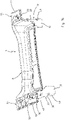
- the figure 15 again shows an instrument panel support 1 .
- the instrument panel support 1 has a cross member 2 .
- the cross member 2 can be integrated between A-pillars (not shown here) of a vehicle body and extends substantially horizontally and transversely between the A-pillars.
- the cross member 2 has a driver-side length section 50 and a passenger-side length section 51 which are coupled to one another.
- the longitudinal section 51 on the passenger side is formed by a straight tube.
- the driver-side length portion 50 is press-formed by U-O forming a sheet metal blank.
- the driver-side cross member end 52 on the left in the image plane has a rectangular configuration and has an assembly opening 53 that is integrated into the tube and passes through the cross member end 52 .
- the cross member 2 is screwed to the body or the A-pillar of the body in the direction of the longitudinal axis of the vehicle (x-axis) via the assembly opening 53 and corresponding assembly elements.
- the cross member end 52 is configured rectangular in vertical cross section and has a height measured in the vehicle vertical axis (z-axis) that is greater than the width measured in the vehicle longitudinal axis (x-axis).
- a holder 54 welded on with a mounting opening 55 is additionally provided.
- the assembly opening 55 is also oriented in the longitudinal axis of the vehicle (x-axis) and is used to fix the instrument panel support 1 or the cross member 2 directly or indirectly to the A-pillar of the vehicle body.
- the rectangular cross section changes into a circular cross section.
- a flat sheet metal blank is produced first formed in a U-shape viewed in cross-section and then formed into an O-shaped or rectangular closed tube.
- the S-shaped contour at the transition from the rectangular to the round cross section is produced by the UO shaping without additional bending operations.
- a first tunnel support 5 between the longitudinal section 50 on the driver's side and the longitudinal section 51 on the passenger's side and a further tunnel support 5 of the longitudinal section 51 of the cross member 2 on the passenger's side connect these to the vehicle floor or a vehicle tunnel.
- a mounting component 3 is also provided on the A-pillar end 57 of the longitudinal section 51 of the cross member 2 on the passenger side.
- This assembly element 3 is welded on and has openings 58 in the longitudinal axis of the vehicle (x-axis) for screwing to the body or the A pillar there.
- Brackets and struts can be provided as an option, for example for air conditioning, steering column attachment, controls or for the dashboard (dashboard) itself.
- end 52 of the cross member on the driver's side passes through a holder component 59 .
- This is used together with a holder component 60 on the passenger side at the end 57 there to fix the dashboard.
Landscapes
- Engineering & Computer Science (AREA)
- Mechanical Engineering (AREA)
- Chemical & Material Sciences (AREA)
- Combustion & Propulsion (AREA)
- Transportation (AREA)
- Manufacturing & Machinery (AREA)
- Physics & Mathematics (AREA)
- Optics & Photonics (AREA)
- Instrument Panels (AREA)
Abstract
Description
- Die Erfindung betrifft einen Instrumententafelträger für ein Kraftfahrzeug, der einen zwischen den A-Säulen einer Kraftfahrzeugkarosserie eingliederbaren Querträger aufweist und eine Instrumententafelträgeranordnung sowie ein Verfahren zu deren Herstellung.
- Instrumententafelträger werden in Kraftfahrzeugen als tragendes Bauteil für diverse Cockpit-Funktionen eingesetzt. Eine der Hauptkomponenten eines Instrumententafelträgers ist der Querträger. Der Querträger ist Teil der Kraftfahrzeugkarosserie und erstreckt sich im Bereich unterhalb der Windschutzscheibe im Wesentlichen horizontal verlaufend quer zwischen den A-Säulen. Der Querträger weist einen fahrerseitigen Längenabschnitt und einen beifahrerseitigen Längenabschnitt auf und ist üblicherweise gegen die Stirnwand, also die Trennwand zwischen Motorraum und Fahrzeuginnenraum, sowie gegen den Fahrzeugboden hin zusätzlich abgestützt.
- Der Querträger hat eine versteifende Funktion innerhalb der Kraftfahrzeugkarosserie und dient zur Befestigung und Aussteifung der Instrumententafel. Neben der Halterung für die Instrumententafel selber sind am Querträger diverse Halterungen vorgesehen, an denen unterschiedliche Fahrzeugfunktionskomponenten wie die Längssäule, Heizungs- und Klimaanlage, Mittelkonsole und/oder ein Head-up-Display (HUD) befestigt werden.
- Ein Head-up-Display (HUD) ist ein Anzeigesystem bzw. -gerät mit dem Informationen in das Sichtfeld eines Nutzers projiziert werden.
- Ein Instrumententafelträger mit einem Querträger, der eine Halterung für die Festlegung eines Head-up-Displays aufweist, ist Gegenstand der vorliegenden Erfindung.
- Die
DE 10 2005 031 357 B4 offenbart ein Kraftfahrzeug und ein Instrumententafelmodul zur Verwendung in dem Kraftfahrzeug mit einem Querträger. Der Querträger weist eine Befestigungsvorrichtung zur Anbindung eines Head-up-Displays bzw. dessen Projektionsvorrichtung auf. - Ein Verfahren zur Montage eines Head-up-Displays an einen Modulquerträger für ein Armaturenbrett offenbart die
DE 10 2017 007 470 B3 . - Durch die
DE 10 2006 025 386 A1 zählt ein Fahrzeugcockpit mit einem Head-up-Display und einem Querträger zum Stand der Technik, bei dem Befestigungsmittel für eine Vormontage des Head-up-Displays an dem Querträger und für eine Endmontage an einem weiteren tragenden Karosserieteil vorgesehen sind. Die Befestigungsmittel weisen einen Halter zur Aufnahme des Head-up-Displays sowie zur Befestigung desselben an dem Querträger auf. - Die Einbaulage und die eindeutige Positionierung des Head-up-Displays im Kraftfahrzeug innerhalb des Armaturenbretts bzw. der Instrumententafelträgeranordnung ist von wesentlicher Bedeutung, um den geforderten Qualitätsmerkmalen, insbesondere den Funktionsmaßen und dem Fugenplan gerecht zu werden. Dementsprechend müssen die Anschraub- bzw. Montageflächen des Head-up-Displays sehr genau sein. Insbesondere müssen die Anschraub- bzw. Montageflächen des Head-up-Displays eine genaue Position in z-Achse im Referenzpunktsystem eines Instrumententafelträgers aufweisen. Weiterhin ist der Kippwinkel des Head-up-Displays um die y-Achse von großer Bedeutung, um den funktionellen Anforderungen gerecht zu werden. Darüber hinaus muss ein Instrumententafelträger und die Instrumententafelträgeranordnung mit einem integrierten Head-up-Display notwendige Sicherheitsbestimmungen, insbesondere auch elektrotechnische Sicherheitsbestimmungen erfüllen.
- Der Erfindung liegt ausgehend vom Stand der Technik die Aufgabe zugrunde, einen Instrumententafelträger mit einer funktional und montagetechnisch verbesserten Halterung für ein Head-up-Display am Querträger zu schaffen und eine Instrumententafelträgeranordnung sowie ein Verfahren zu deren Herstellung aufzuzeigen.
- Die Lösung dieser Aufgabe besteht nach der Erfindung in einem Instrumententafelträger gemäß Anspruch 1.
- Vorteilhafte Ausgestaltungen und Weiterbildungen der Erfindung sind Gegenstand der abhängigen Ansprüche.
- Eine Instrumententafelträgeranordnung mit einem erfindungsgemäßen Instrumententafelträger ist Gegenstand von Anspruch 17.
- Ein Verfahren zur Herstellung einer Instrumententafelträgeranordnung zeigt Anspruch 18 auf.
- Der Instrumententafelquerträger für ein Kraftfahrzeug weist einen zwischen den A-Säulen einer Kraftfahrzeugkarosserie eingliederbaren und an den A-Säulen festlegbaren Querträger auf. Am Querträger ist eine Halterung für ein Head-up-Display (HUD) angeordnet. Erfindungsgemäß weist die Halterung einen Tragkörper für das Head-up-Display auf, wobei der Tragkörper über Stützen am Querträger festgelegt ist. Der Tragkörper besitzt Flanschabschnitte mit Montageöffnungen zur Befestigung des Head-up-Displays. Im Bereich einer Montageöffnung ist ein elektrisch nicht leitendes Koppelglied vorgesehen.
- Das elektrisch nicht leitende Koppelglied ist den Montageöffnungen kraft- und/oder formschlüssig zugeordnet. Das bzw. die elektrisch nicht leitenden Koppelglieder sind werkstoffmäßig und konfigurativ dazu ausgelegt und eingerichtet eine galvanische Trennung zwischen einem am bzw. im Tragkörper montierten Head-up-Display und den metallischen Bauteilen des Instrumententafelträgers innerhalb der Instrumententafelträgeranordnung sicherzustellen. Nicht leitend bzw. nicht leitfähig bedeutet, dass die Koppelglieder insbesondere aus einem Nichtleiterwerkstoff bestehen bzw. aus Stoffen bestehen, die an Leitfähigkeit in die Kategorie Nichtleiter einzustufen ist. Wesentlich ist, dass die nichtleitenden Koppelglieder eine galvanische Trennung zwischen Tragkörper und einem montierten Head-up-Display sicherstellen. Das Head-up-Display bzw. das Gehäuse des Head-up-Displays soll nicht Teil der elektrischen Masse der Karosserie sein. Diese Anforderung wird durch die elektrisch nicht leitenden Koppelglieder realisiert, die eine galvanische Trennung zwischen dem Tragkörper und dem Head-up-Display bewirken.
- Die Halterung umfasst den Tragkörper für das Head-up-Display der an Stützen festgelegt ist. Insbesondere ist der Tragkörper zwischen zwei seitlichen Stützen geschweißt. Die Stützen ihrerseits sind am Querträger schweißtechnisch stoffschlüssig gefügt. Die Ausgestaltung ermöglicht es die Halterung beim Verschweißen in z-Achse (Fahrzeughochachse) positionsgerecht einzustellen und festzulegen. Auf diese Weise können auch Formabweichungen bzw. Toleranzen des Querträgers in z-Achse kompensiert werden. Ferner kann die Halterung durch Rotation bzw. Verkippen um die y-Achse positionsgerecht eingerichtet und gefügt werden. Insgesamt sind engere Toleranzen erreichbar und zwar mit einem rationellen schweißtechnischen Fügeverfahren der Bauteile von Querträger und Haltung sowie deren Stützen und Tragkörper untereinander.
- Der Querträger wird, um seiner Funktion im Instrumententafelträger und innerhalb der Instrumententafelträgeranordnung gerecht zu werden, mit diversen Halterbauteilen bestückt. Hierbei handelt es sich um metallische Halterbauteile, die schweißtechnisch am Querträger festgelegt werden. Durch diese schweißtechnischen Fügevorgänge kommt es zu einem Verzug des Querträgers und der Relativlage von Montagepunkten für die verschiedenen Funktionskomponenten, insbesondere auch der Halterung für das Head-up-Display. Ein solcher Schweißverzug ebenso wie unvermeidliche Toleranzen im Fügeprozess werden bei der Positionierung des Tragkörpers relativ zu den Stützen ausgeglichen. Die Seitenwände des Tragkörpers liegen an den jeweils benachbarten Innenseiten der Stützen an und werden mit den Stützen schweißtechnisch gefügt. Hierbei wird die korrekte Position des Tragkörpers innerhalb der Halterung eingestellt, so dass bei der späteren Montage eines Head-up-Displays keine Justierung der Position des Head-up-Displays während oder nach der Montage erforderlich ist.
- Ein bevorzugter Aspekt der Erfindung ist, dass die Halterung und insbesondere deren Tragkörper relativ zu den Stützen positionsgerecht ausgerichtet wird, insbesondere in z-x-Ebene und in dieser Endlage eine stoffschlüssige Fügung zwischen Tragkörper und Stützen erfolgt. Die Stützen weisen Anlageflächen bzw. Fügeflächen an seitlichen Schenkeln auf, welche die Seitenwände des Tragkörpers außenseitig kontaktieren. Der Tragkörper ist mit den Stützen im Bereich der Anlageflächen verschweißt.
- Der Tragkörper wird mit den an den Montageflanschen vorgesehen elektrisch nicht leitenden Koppelgliedern im Bereich der Montageöffnung bereitgestellt und mit den Stützten gefügt. Die Stützen selbst sind vorteilhafter Weise vor der Fügung des Tragkörpers am Querträger schweißtechnisch festgelegt.
- Eine bevorzugte Ausführungsform sieht vor, dass die Halterung zwischen zwei Stützen gefügt wird. Eine Stütze weist vorzugsweise einen an die Außenkontur des Querträgers konfigurativ angepassten Stützenfuß auf. Der Stützenfuß umgreift den Querträger bereichsweise und ist mit dem Querträger stoffschlüssig gefügt, insbesondere verschweißt.
- Eine Stütze ist vorzugsweise im horizontalen Querschnitt, insbesondere im Stützenfuß, u-förmig konfiguriert mit einem Steg und zwei Schenkeln.
- Zwei Stützen sind in Längsrichtung (y-Achse) des Querträgers mit axialem Abstand zueinander angeordnet. Die Stege jeder Stütze verlaufen in x-Achse. Die Schenkel der Streben sind vom Steg in Richtung zum Tragkörper gerichtet. Zwischen den Stützen ist der Tragkörper aufgenommen.
- Eine Stütze weist Anlageflächen für den Tragkörper auf. Diese sind vorzugsweise an dem Schenkel vorgesehen, insbesondere an den Stirnseiten der Schenkel. Der Tragkörper liegt mit seinen Seitenwänden an den Anlageflächen an und ist stoffschlüssig gefügt.
- Eine vorteilhafte Ausgestaltung des erfindungsgemäßen Instrumententafelträgers sieht vor, dass benachbart zumindest einer Montageöffnung ein Positionierelement für das Head-up-Display vorgesehen ist. Ein Positionierelement dient als Montagehilfe und zur Erleichterung des Einbaus und der Ausrichtung des Head-up-Displays in der Halterung und der Instrumententafelträgeranordnung. Ein Positionierelement ist bevorzugt als Durchbrechung bzw. Loch, insbesondere Langloch, benachbart zu einer Montageöffnung ausgestaltet. Vorteilhafterweise ist das Positionierelement an bzw. innerhalb des Bereichs eines elektrisch nicht leitenden Koppelglieds ausgebildet. Eine Positionierhilfe in Form eines Lochs dient zur Aufnahme eines am Head-up-Display vorgesehenen Pins über welchen das Head-up-Display bei der Montage ausgerichtet werden kann.
- Am oberen Ende einer Seitenwand ist ein Flanschabschnitt vorgesehen. Die Flanschabschnitte sind von der Seitenwand aus nach außen (y-Achse) gerichtet. Eine für die Praxis besonders vorteilhafte Ausführungsform sieht vor, dass zumindest ein Flanschabschnitt eines Tragkörpers zwei in x-Achse (Fahrzeuglängsachse) mit Abstand zueinander angeordnete Montageöffnungen aufweist. Benachbart zu einer der beiden Montageöffnungen in einem Flanschabschnitt ist ein Positionierelement, insbesondere ein Loch, vorgesehen.
- Bevorzugt besteht ein elektrisch nicht leitendes Koppelglied aus Kunststoff. Das Koppelglied kann einen Flanschabschnitt oberseitig und/oder unterseitig zumindest bereichsweise abdecken. Des Weiteren kann das Koppelglied die Montageöffnung innenseitig abdecken. Hierbei ist die innere Umfangswand der Montageöffnung von dem Werkstoff des Koppelglieds abgedeckt bzw. mit dem Werkstoff des Koppelglieds beschichtet.
- Eine weitere Ausgestaltung sieht vor, dass in dem Koppelelement ein Schraubverbindungselement integriert ist. Ein Schraubverbindungselement kann aus dem Werkstoff des Koppelelements selbst ausgestaltet sein oder aber durch ein separates Bauteil gebildet werden. Ein Schraubverbindungselement ist insbesondere eine Gewindemutter oder Gewindehülse, in welche eine Montageschraube zur Montage eines Head-up-Displays eingeschraubt werden kann.
- Vorzugsweise weist das Koppelglied einen Stutzenkörper auf. Der Stutzenkörper ist insbesondere in Fortsetzung einer Montageöffnung an der Unterseite eines Koppelglieds bzw. der Unterseite eines Flanschabschnitts vorgesehen. Der Stutzenkörper und die Montageöffnung weisen eine gemeinsame Mittelachse auf. Ein in das Koppelglied integriertes Schraubverbindungselement ist insbesondere im Stutzenkörper angeordnet und dient als Widerlager für eine Montageschraube.
- Eine in der Praxis besonders vorteilhafte Ausgestaltung sieht vor, dass das Koppelglied in Form eines Clips ausgeführt ist. Ein solcher Koppelglied-Clip ist seitlich auf einen Flanschabschnitt aufgesetzt und umklammert den Bereich einer Montageöffnung ober- und unterseitig. Ein Koppelglied-Clip hält selbsttätig federklemmend an einem Flanschabschnitt. Ein Koppelglied-Clip kann Rastelemente aufweisen, beispielsweise mit Rastnase versehene Federschenkel, welche mit Gegenflächen am Montageflansch zusammendrücken oder aber Durchbrechungen an einem Montageflansch durchgreifen. Im Koppelglied-Clip sind zu einer Montageöffnung kongruente Durchführöffnungen vorgesehen. Gleiches gilt für ein Positionierelement in Form eines Loches. Ein Koppelglied-Clip weist eine Durchbrechung auf die sich mit dem Positionierloch deckt.
- Bei einer alternativen Ausführungsform des Koppelglieds ist dieses als Spritzteil ausgeführt. Hierbei ist der Bereich um eine Montageöffnung im Flanschabschnitt mit einem elektrisch nicht leitfähigen Werkstoff, insbesondere Kunststoff, umspritzt. Zu einer Montageöffnung benachbarte Positionierelemente, insbesondere ein Positionierloch, sind ebenfalls umspritzt.
- Ein Kopplelglied kann als Kunststoffclip mit einem integrierten Gewindeeinsatz oder einer Kunststoff-Umspritzung mit einem Gewindeeinsatz ausgebildet sein. Ein Gewindeeinsatz ist insbesondere eine Schraubmutter, in welche eine Montageschraube zur Montage und Festlegen eines Head-up-Displays eingeschraubt werden kann.
- Eine zum Gewindeeinsatz bzw. zur Schraubenmutter passende Montageschraube des bzw. für das Head-up-Display kann elektrisch isolierend beschichtet ausgebildet sein und/oder nur mit dem Head-up-Display elektrisch isoliert in Kontakt stehen.
- Die erfindungsgemäße Ausgestaltung ermöglicht, die Halterung beim Fügen zu den Stützen einzustellen, insbesondere in z-Richtung. Auf diese Weise können Formabweichungen des Querträgers, insbesondere in z-Richtung, kompensiert werden. Darüber hinaus kann eine Verkippung um die y-Achse in vorteilhafter Weise kompensiert und die korrekte Lage der Halterung eingestellt werden. Insgesamt gewährleistet die Erfindung, dass engere Toleranzen erreichbar sind, wobei die Fertigung durch einen stoffschlüssigen Standardprozess mittels Schweißen erfolgt. Hierdurch können Taktzeiten erhöht und die Fertigung insgesamt rationeller erfolgen.
- Der Tragkörper weist zwei in Längsrichtung (y-Achse) des Querträgers axial mit Abstand angeordnete Seitenwände auf. Die Seitenwände sind in Fahrzeuglängsasche (x-Achse) orientiert und erstrecken sich quer zur Längsrichtung des Querträgers. Zwischen den Seitenwänden erstrecken sich in Längsrichtung des Tragkörpers, also in y-Achse, zwischen den Seitenwänden Längswände, insbesondere eine Rückwand oder Längswandstreben und/oder bodenseitig des Tragkörpers ein Boden oder Bodenabschnitte oder Bodenstreben.
- Eine vorteilhafte Ausgestaltung sieht vor, dass der Tragkörper einen Aufnahmeraum bereitstellt, in welchem ein Head-up-Display geschützt aufgenommen werden kann. Der Aufnahmekörper ist durch die Seitenwände und zumindest eine Längswand, insbesondere eine Rückwand, sowie Längswandstreben und/oder Bodenstreben begrenzt. Die Seitenwände sind untereinander biegesteif verbunden. Dies erfolgt über zumindest eine Längswand sowie Längswandstreben und/oder Bodenstreben. Dies ermöglicht eine besonders vorteilhafte Aufnahme und Halterung für ein Head-up-Display. Front- oder rückseitig, insbesondere frontseitig, kann der Tragkörper offen sein. Dies verbessert die Montierbarkeit eines Head-up-Displays und dessen Zugänglichkeit. Der Tragkörper kann vorder- und/oder rückseitige Längswände zwischen den Seitenwänden aufweisen, die eine geringere Höhe haben als die Seitenwände. Insbesondere erstreckt sich zwischen den hinteren Enden der Seitenwände eine Rückwand, die in z-Achse weniger hoch ist als die Seitenwände. Frontseitig ist der wannenförmige Tragkörper im Wesentlichen offen. Entlang des Bodens erstreckt sich zwischen den Seitenwänden eine Längswandstrebe, die am Boden als Umstellung ausgeführt ist.
- Eine Stütze ist außenseitig jeweils an einer Seitenwand des Tragkörpers an dieser anliegend stoffschlüssig gefügt. An den Seitenwänden und/oder den Stützen können Positionier- und/oder Fügehilfen beispielsweise in Form von Markern vorgesehen sein. Marker können durch Materialverprägungen, Materialumstellungen, Sicken und/oder auch Durchbrechungen bzw. Löcher gebildet sein.
- Ein Fügebereich zwischen den Stützen und den Seitenwänden des Tragkörpers erstreckt sich innerhalb einer z-x-Ebene. Die Anlageflächen, insbesondere an den Schenkeln einer Stütze können einen gemeinsamen Fügebereich bilden. Möglich ist es auch, dass die Anlageflächen und damit die Fügeflächen in der z-x-Ebene versetzt sind. Dies kann beispielsweise durch eine unterschiedliche Schenkellänge erfolgen. Auch können die Schenkel konfigurativ so ausgelegt werden, dass Anlageflächen und damit Fügeflächen in dreidimensional zueinander verschobenen Positionen vorhanden sind.
- Der Tragkörper weist einen Boden auf. Vorzugsweise ist der Tragkörper bodenseitig bereichsweise offen ausgeführt. Diese Maßnahme trägt zur Gewichtsreduzierung der Halterung bei. Insbesondere weist der Tragkörper einen Boden auf mit Aufnehmung und/oder Durchzügen und/oder Öffnungen, wobei eine Öffnung einen randseitig umlaufenden Kragen oder randseitige Kragenabschnitte aufweisen kann.
- Eine Instrumententafelträgeranordnung weist einen erfindungsgemäßen Instrumententafelträger sowie ein an der Halterung montiertes Head-up-Display auf.
- Ein Verfahren zur Herstellung einer solchen Instrumententafelträgeranordnung umfasst die folgenden Schritte:
- Bereitstellen eines metallischen Querträgers, der dazu bestimmt und ausgelegt ist, zwischen den A-Säulen einer Kraftfahrzeugkarosserie eingegliedert zu werden;
- schweißtechnische Fügung einer Mehrzahl von metallischen Halterbauteilen am Querträger, wobei zumindest zwei metallische Stützen am Querträger festgelegt werden, welche dafür ausgelegt und bestimmt sind, mit einem Tragkörper für ein Head-up-Display gekoppelt zu werden;
- Bereitstellen eines Tragkörpers für ein Head-up-Display, welcher zwei mit Abstand zueinander angeordnete Seitenwände aufweist, die untereinander biegesteif verbunden sind;
- Positionieren des Tragkörpers relativ zu den Stützen und Ausrichten des Tragkörpers relativ zu den Stützen in z-x-Ebene;
- Schweißtechnische Fügung des Tragkörpers zwischen den Stützen;
- Bereitstellen und Montage eines Head-up-Displays in der Halterung.
- Ein vorteilhafter Aspekt hierbei ist, dass der Tragkörper relativ zu den am Querträger bereits gefügten Stützen in z-Achse (Fahrzeughochachse) und in x-Achse (Fahrzeuglängsachse), also in der z-x-Ebene, positionsgerecht ausgerichtet und dann stoffschlüssig mit den Stützen verschweißt wird. Dies erfolgt mit einer geeigneten Schweißvorrichtung bzw. Schweißlehre. Die Halterung ist nach dem Verschweißen der Komponenten zur Aufnahme des Head-up-Displays bereit. Eine nachträgliche Justierung des Head-up-Displays selbst muss nicht mehr erfolgen.
- Eine die Funktionalität eines Instrumententafelträgers verbessernde Ausgestaltung sieht vor, dass der Querträger einen fahrerseitigen Längenabschnitt mit einem Querträgerende aufweist, wobei das Querträgerende eine Montageöffnung besitzt, welche den fahrerseitigen Längenabschnitt bzw. den fahrerseitigen Längenabschnitt im Bereich des Querträgerendes in Fahrzeuglängsachse (x-Achse) durchsetzt. Die Querschnittsgeometrie zusammen mit der Festlegung des Querträgers in Fahrzeuglängsachse (x-Achse) gewährleistet eine vorteilhafte Montage und eine im statischen und dynamischen Belastungsverhalten vorteilhafte Festlegung des Instrumententafelträgers innerhalb einer Kraftfahrzeugkarosserie. Besonders vorteilhaft weist das Querträgerende im vertikalen Querschnitt eine rechteckige Konfiguration auf mit einer in Fahrzeughochachse (z-Achse) gemessenen Höhe, die größer ist als die in Fahrzeuglängsachse (x-Achse) gemessene Breite.
- Ausführungsformen der Erfindung und erfindungsgemäße Aspekte sind in den nachfolgenden Zeichnungen dargestellt und beschrieben. Es zeigen:
- Figur 1
- eine Ansicht auf einen erfindungsgemäßen Instrumententafelträger;
- Figur 2
- den fahrerseitigen Längenabschnitt des Instrumententafelträgers gemäß der Darstellung von
Figur 1 ; - Figur 3
- technisch schematisiert und stark vereinfacht eine Seitenansicht auf einen Instrumententafelträger;
- Figur 4
- eine erste Ausführungsform einer Halterung für ein Head-up-Display in einer perspektivischen Darstellung;
- Figur 5
- die Halterung aus einer anderen Perspektive;
- Figur 6
- die Darstellung gemäß der
Figur 4 in einer Draufsicht; - Figur 7
- einen Ausschnitt aus der Halterung in einer Perspektive;
- Figur 8
- den Ausschnitt entsprechend der Darstellung von
Figur 7 in einer Seitenansicht; - Figur 9
- eine zweite Ausführungsform einer Halterung für ein Head-up-Display in einer Perspektive,
- Figur 10
- die Halterung gemäß der Darstellung von
Figur 9 aus einer anderen Perspektive; - Figur 11
- die Darstellung gemäß der
Figur 9 in einer Draufsicht; - Figur 12
- einen Ausschnitt aus der Halterung gemäß der Darstellung der
Figuren 9 bis 11 in einer perspektivischen Ansicht; - Figur 13
- eine schematisierte Seitenansicht auf den Ausschnitt entsprechend der
Figur 12 ; - Figur 14
- eine weitere Ausführungsform einer Halterung für ein Head-up-Display in einer Perspektive und
- Figur 15
- eine Ansicht auf eine weitere Ausführungsform eines Instrumententafelträgers.
- In den Figuren werden für gleiche oder funktionell einander entsprechende Bauteile bzw. Bauteilkomponenten die gleichen Bezugszeichen verwendet. Gleiches gilt für dargestellte Bemaßungen und/oder Abmessungen.
- Begriffe wie oben und unten, vorne und hinten, horizontal und vertikal oder Längsrichtung und Querrichtung sowie Oberseite und Unterseite, Fahrerseite, fahrerseitig, Beifahrerseite oder beifahrerseitig beziehen sich auf die Einbaulage des Querträgers zwischen den A-Säulen innerhalb einer Kraftfahrzeugkarosserie oder der Montagelage der Halterung am Querträger und relativ zum Querträger.
- Ein Fahrzeugkoordinatensystem ist ein dreidimensionales kartesisches Koordinatensystem, um die Achsen innerhalb eines Kraftfahrzeugs zu kennzeichnen. Der Ursprung des Koordinatensystems liegt in der Fahrzeugmittelebene. Die x-Achse entspricht der Fahrzeuglängsachse, die y-Achse der Fahrzeugquerachse und die z-Achse der Fahrzeughochachse.
- Die
Figur 1 zeigt einen Instrumententafelträger 1.Figur 2 zeigt den fahrerseitigen Längenabschnitt des Instrumententafelträgers 1 gemäß der Darstellung vonFigur 1 in einer vergrößerten Darstellung. -
Figur 3 zeigt eine technisch schematisierte und stark vereinfachte Seitenansicht auf einen Instrumententafelträger 1. - Der Instrumententafelträger 1 weist einen Querträger 2 auf. Der Querträger 2 ist zwischen hier nicht dargestellten A-Säulen einer Kraftfahrzeugkarossiere eingliederbar und erstreckt sich im Wesentlichen horizontal verlaufend in Fahrzeugquerachse (y-Achse) quer zwischen den A-Säulen. Die Festlegung des Querträgers 2 an den A-Säulen erfolgt über endseitig des Querträgers 2 vorgesehene Montagebauteile 3.
- Der Querträger 2 besteht aus Stahl. Am Querträger 2 sind diverse Halter für Fahrzeugfunktionskomponenten gefügt. Exemplarisch bezeichnet sind ein Lenkerhalter 4 sowie Stützstreben 5.
- Der Querträger 2 weist eine Halterung 6 für ein Head-up-Display 7 (HUD) auf.
- Die
Figuren 4 bis 7 zeigen eine erste Ausführungsform einer Halterung 6. - Anhand der
Figuren 8 bis 11 ist eine zweite Ausführungsform einer Halterung 6 für ein Head-up-Display 7 beschrieben. - Eine Halterung 6 umfasst einen Tragkörper 8 für ein Head-up-Display 7. Der Tragkörper 8 ist bevorzugt wannenförmig konfiguriert. Der Tragkörper 8 weist zwei in y-Achse mit Abstand zueinander angeordnete Seitenwänden 9, 10 auf. Zwischen den Seitenwänden 9, 10 erstreckt sich eine hintere geschlossene Rückwand 11. Bodenseitig zwischen den Seitenwänden 9, 10 erstreckt sich ein Boden 12 des Tragkörpers 8. Der Boden 12 ist bereichsweise offen und weist Ausnehmungen 13 auf. Zwischen den im Ausführungsbeispiel zwei Ausnehmungen 13 des Tragkörpers 8 erstreckt verläuft eine Querstrebe 14. Die Querstrebe 14 erstreckt sich in x-Achse zwischen einer hinteren Bodenstrebe 15 und einer vorderen Bodenstrebe 16 jeweils über die Länge des Bodens 12 verlaufend. Vorderseitig ist der Tragkörper 8 offen. Die vordere Bodenstrebe 16 geht gerundet in eine nach vorne gerichtete Längswandstrebe 17 über. Die Längswandstrebe 17 erstreckt sich zwischen den Seitenwänden 9 und 10.
- Der Tragkörper 8 weist an den oberen Enden 18 der Seitenwände 9, 10 in y-Achse jeweils nach außen gerichtete Flanschabschnitte 19, 20 auf. Die Flanschabschnitte 19, 20 erstrecken sich entlang der Seitenwände 9, 10. In den Flanschabschnitten 19, 20 sind Montageöffnungen 21, 22 vorgesehen. Die Montageöffnungen 21, 22 durchsetzen die Flanschabschnitte 19, 20 in z-Achse. Die Montageöffnungen 21, 22 dienen zur Befestigung des Head-up-Displays 7.
- Der Flanschabschnitt 19 an der Seitenwand 9 ist länger als der Flanschabschnitt 20 an der gegenüberliegenden Seitenwand 10. Im mittleren Längenabschnitt ist im Übergang 23 von der Seitenwand 9 vom Flanschabschnitt 19 eine Sicke 24 vorgesehen. Die Sicke 24 ist von der Innenseite des Tragkörpers 8 nach außen geprägt und erstreckt sich in y-Achse bereichsweise über den Flanschabschnitt 19.
- Benachbart zur in Bildebene hinteren Montageöffnung 21 in Flanschabschnitt 19 und benachbart zur Montageöffnung 21 im Flanschabschnitt 20 ist ein Positionierelement 25 in Form eines Lochs bzw. Langlochs vorgesehen.
- Die Seitenwände 9, 10 sind in z-Achse länger als die Rückwand 11, so dass die Seitenwände 9, 10 höher sind als die Rückwand 11. Am rückwandseitigen Ende der Flanschabschnitte 19, 20 gehen diese jeweils von der Seitenwand 9 bzw. 10 über einen gekrümmt verlaufenden und sich verjüngenden Übergangsabschnitt 26 in die Rückwand 11 über.
- Der Tragkörper 8 ist über Stützen 27, 28 am Querträger 2 festgelegt. Jede Stütze 27, 28 weist einen an die Außenkontur des Querträgers 2 konfigurativ angepassten Stützenfuß 29 auf. Die Stützen 27, 28 sind im horizontalen Querschnitt u-förmig konfiguriert mit einem Steg 30 und jeweils an dem Steg 30 in x-Achse umgestellten Schenkeln 31, 32. Der Säulenfuß 29 steht auf dem Außenumfang des Querträgers 2 auf und umgreift diesen bereichsweise. Jede Stütze 27, 28 ist im Querträger 2 verschweißt. Nach oben in Richtung zum freien bzw. tragkörperseitigen Ende 33 verjüngen sich die Stützen 27, 28. Die Schenkel 31, 32 sind im Bereich des Säulenfuß 29 länger ausgeführt als am tragkörperseitigen oberen Ende 33. Die Stützen 27, 28 weisen Anlageflächen 34 auf. An den Anlageflächen 34 einer Stütze 27, 28 liegt ein Tragkörper 8 mit seinen Seitenwände 9 bzw. 10 an und ist mit den Stützen 27, 28 gefügt. Beim Fügevorgang kann die Position des Tragkörpers 8 in z-Achse relativ zu den Stützen 27, 28 eingestellt werden. Durch Rotation um die y-Achse erfolgt eine Ausrichtung des Tragkörpers 8 im Kippwinkel. Die korrekte Position und Lage der Halterung 6 in y-Achse erfolgt über die Position der Stützen 27, 28 am Querträger 2.
- Im Bereich einer Montageöffnung 21, 22 ist jeweils ein elektrisch nicht leitendes Koppelglied 35, 36 angeordnet. Ein Koppelglied 35, 36 deckt jeweils den zu einer Montageöffnung 21,22 einschließlich eines Positionierelements 25 benachbarten Bereich des Flanschabschnitts 19 bzw. 20 ober- und unterseitig ab. Ein Koppelglied 35, 36 deckt auch den inneren Umfang der Montageöffnung 21, 22 und das Loch bzw. die innere Lochwandung des Positionierelements 25 elektrisch isolierend ab. Abdecken bedeutet, dass das Koppelglied 35, 36 an den Flächen anliegt, diese beschichtet und das Koppelglied 35, 36 eine Montageöffnung 21, 22 auskleidet. Ein elektrisch nicht leitendes Koppelglied 35, 36 ist dafür ausgelegt und eingerichtet eine galvanische Trennung zwischen der Halterung 6 und dem Head-up-Display 7 zu bewirken.
- Die Halterung 6 wie anhand der
Figuren 4 bis 8 beschrieben und die Halterung 6 wie anhand derFiguren 9 bis 13 beschrieben unterscheiden sich durch die Ausführung der Koppelglieder 35 bzw. 36. - Das Koppelglied 35 der Halterung 6 gemäß der Darstellungen der
Figuren 4 bis 8 ist in Form eines Clips 37 ausgeführt. - Das Koppelglied 36 der Halterung 6 entsprechend der Darstellung der
Figuren 9 bis 12 ist als Spritzteil 38 ausgeführt. - Ein Koppelglied 35 in der Ausgestaltung als Clip 37 besteht aus Kunststoff und weist einen oberen Klammerabschnitt 39 und einen unteren Klammerabschnitt 40 auf, die jeweils einen Flanschabschnitt 19, 20 umgreifen. An den vom Flanschabschnitt 19, 20 abgewandten Ende sind der obere Klammerabschnitt 39 und der untere Klammerabschnitt 40 durch Bügel 41 verbunden.
- Am unteren Klammerabschnitt 40 erstreckt sich ein Stutzenkörper 42 abwärts. Der Stutzenkörper 42 weist eine Längsöffnung auf, welche die Fortsetzung einer Montageöffnung 21 bildet. Im Stutzenkörper 42 ist ein Schraubverbindungselement 43 in Form einer Gewindehülse integriert (siehe hierzu insbesondere
Figuren 7 und 8 ). - Der Clip 37 weist Rastelemente 44 auf in Form eines Federschenkels, der eine Rastnase besitzt. Das Rastelement 44 durchgreift eine Öffnung 45 im Flanschabschnitt 19 und im unteren Klammerabschnitt 40 und rastet am unteren Klammerabschnitt widerlagernd ein.
- Oberseitig besitzt das Koppelglied 35 in Form des Clips 37 eine Anlagefläche 46. Dort kann ein Montagelement, insbesondere ein Schraubbolzen, mit seinem Schraubkopf zur Anlage kommen. Die Anlagefläche 46 ist gegenüber der äußeren Oberseite des Koppelglieds 35 abgesetzt, d.h., abgesenkt bzw. vertieft. Die Anlagefläche 46 umschließt eine Montageöffnung 21, 22.
- Die elektrisch nicht leitenden Koppelglieder 36 wie in den
Figuren 9 bis 13 dargestellt sind als Spritzteil 38 aus Kunststoff hergestellt. Ein Koppelglied 36 ist im Bereich jeweils einer Montageöffnung 21, 22 ausgebildet und deckt die Bereiche des Flanschabschnittes 19, 20 ober- und unterseitig ab. Des Weiteren werden die innere Umfangswand der Montageöffnungen 21, 22 und das Loch des Positionierelements 25 vom aufgespritzten Werkstoff des elektrisch nicht leitenden Koppelglieds 36 abgedeckt bzw. beschichtet. - Auch im Koppelglied 36 ist ein Schraubverbindungselement 43 integriert. Hierzu ist am elektrisch nicht leitenden Koppelglied 36 ein Stutzenkörper 42 spritztechnisch hergestellt. Das Schraubverbindungselement 43 in Form einer Gewindehülse durchsetzt das Koppelglied 36 und bildet den Bestandteil der Montageöffnung 21 (siehe
Figur 13 ). - Der Querträger 2 und die Halterung 6 bzw. deren Tragkörper 8 und die Stützen 27, 28 bestehen aus Stahl. Die elektrisch nicht leitenden Koppelglieder 35, 36 bestehen aus einem elektrisch nicht leitenden Werkstoff, insbesondere Kunststoff und sind so dimensioniert, dass eine galvanische Trennung zwischen den Bauteilen der Halterung 6 und einem montierten Head-up-Display 7 gewährleistet ist.
- Die
Figur 14 zeigt eine weitere Ausführungsform einer Halterung 6 für ein Head-up-Display 7. Die Halterung 6 entspricht im Wesentlichen der Halterung 6, wie anhand derFiguren 3 bis 6 beschrieben. Auf die dortige Beschreibung wird daher verwiesen. Der Tragkörper 8 ist über Stützen 27, 28 am Querträger 2 festgelegt. In den vertikal verlaufenden Kanten 48 am Übergang zwischen dem Steg 30 und einem Schenkel 31 sind sich quer über die Kante 48 erstreckende Sicken 49 vorgesehen. Die Sicken 49 versteifen die Stützen 27 und 28. - Die bei der Halterung 6 bzw. dem Tragkörper 8 zum Einsatz gelangenden Koppelglieder 35 sind in Form von Clips 37 ausgeführt, wobei an beiden Flanschabschnitten 19, 20 und den dortigen Montageöffnungen 21, 22 jeweils gleichartige Clips 37 zum Einsatz gelangen.
- Die
Figur 15 zeigt wiederum einen Instrumententafelträger 1. Der Instrumententafelträger 1 weist einen Querträger 2 auf. Der Querträger 2 ist zwischen hier nicht dargestellten A-Säulen einer Fahrzeugkarosserie eingliederbar und erstreckt sich im Wesentlichen horizontal verlaufend quer zwischen den A-Säulen. - Der Querträger 2 weist einen fahrerseitigen Längenabschnitt 50 und einen beifahrerseitigen Längenabschnitt 51 auf, die miteinander gekoppelt sind. Der beifahrerseitige Längenabschnitt 51 ist durch ein geradlinig verlaufendes Rohr gebildet. Der fahrerseitige Längenabschnitt 50 ist durch ein U-O-Formen eines Blechzuschnitts pressgeformt.
- Das in Bildebene linke fahrerseitige Querträgerende 52 ist rechteckig konfiguriert und weist eine rohrintegrierte und das Querträgerende 52 durchsetzende Montageöffnung 53 auf. Über die Montageöffnung 53 und entsprechende Montageelemente erfolgt die Verschraubung des Querträgers 2 in Richtung der Fahrzeuglängsachse (x-Achse) an der Karosserie bzw. der A-Säule der Karosserie. Das Querträgerende 52 ist im vertikalen Querschnitt rechteckig konfiguriert und besitzt eine in Fahrzeughochachse (z-Achse) gemessene Höhe, die größer ist als die in Fahrzeuglängsachse (x-Achse) gemessene Breite.
- Unter dem fahrerseitigen Querträgerende 52 ist zusätzlich ein angeschweißter Halter 54 mit einer Montageöffnung 55 vorgesehen. Auch die Montageöffnung 55 ist in Fahrzeuglängsachse (x-Achse) orientiert und dient zur Fixierung des Instrumententafelträgers 1 bzw. des Querträgers 2 mittelbar oder unmittelbar an der A-Säule der Fahrzeugkarosserie.
- In Richtung zum beifahrerseitigen Längenabschnitt 51 geht der rechteckige Querschnitt in einen kreisförmigen Querschnitt über. Bei der pressformtechnischen Herstellung des fahrerseitigen Längenabschnitts 50 wird eine ebene Blechplatine zunächst im Querschnitt betrachtet U-förmig eingeformt und anschließend zum geschlossenen Rohr O-förmig bzw. rechteckig umgeformt. Der S-förmige Konturverlauf am Übergang vom rechteckigen zum runden Querschnitt ist durch die U-O-Formgebung ohne zusätzliche Biegeoperationen hergestellt.
- An dem S-förmigen Übergang im fahrerseitigen Längenabschnitt 50 schließt sich ein gradlinig verlaufender Lenkerabschnitt 56 an. Oberhalb des Lenkerabschnitts 56 ist die Halterung 6 für ein Head-up-Display stoffschlüssig gefügt. Die Halterung 6 ist mit den Stützen 27, 28 auf dem Lenkerabschnitt 56 geschweißt.
- Eine erste Tunnelstütze 5 zwischen dem fahrerseitigen Längenabschnitt 50 und dem beifahrerseitigen Längenabschnitt 51 sowie eine weitere Tunnelstütze 5 des beifahrerseitigen Längenabschnitts 51 des Querträgers 2 verbinden diese mit dem Fahrzeugboden oder einem Fahrzeugtunnel.
- Am A-säulenseitigen Ende 57 des beifahrerseitigen Längenabschnitts 51 des Querträgers 2 ist ebenfalls ein Montagebauteil 3 vorgesehen. Dieses Montageelement 3 ist angeschweißt und weist Öffnungen 58 in der Fahrzeuglängsachse (x-Achse) zur Verschraubung an der Karosserie bzw. der dortigen A-Säule auf.
- Optional können weitere Halterungen und Streben vorgesehen sein, beispielsweise für Klimaanlage, Lenksäulenbefestigung, Bedienelemente oder für das Armaturenbrett (Dashboard) selbst.
- Man erkennt des Weiteren, dass das fahrerseitige Querträgerende 52 ein Halterbauteil 59 durchsetzt. Dieses dient zusammen mit einem Halterbauteil 60 auf der Beifahrerseite am dortigen Ende 57 zur Festlegung des Armaturenbretts.
-
- 1 -
- Instrumententafelträger
- 2 -
- Querträger
- 3 -
- Montagebauteile
- 4 -
- Lenkerhalter
- 5 -
- Stützstreben
- 6 -
- Halterung
- 7 -
- Head-up-Display
- 8 -
- Tragkörper
- 9 -
- Seitenwand
- 10 -
- Seitenwand
- 11 -
- Rückwand
- 12 -
- Boden
- 13 -
- Ausnehmungen
- 14 -
- Querstrebe
- 15 -
- hintere Bodenstrebe
- 16 -
- vordere Bodenstrebe
- 17 -
- Längswandstrebe
- 18 -
- oberes Enden von 9, 10
- 19 -
- Flanschabschnitt
- 20 -
- Flanschabschnitt
- 21 -
- Montageöffnung
- 22 -
- Montageöffnung
- 23 -
- Übergang
- 24 -
- Sicke
- 25 -
- Positionierelement
- 26 -
- Übergangabschnitt
- 27 -
- Stütze
- 28 -
- Stütze
- 29 -
- Stützenfuß
- 30 -
- Steg
- 31 -
- Schenkel
- 32 -
- Schenkel
- 33 -
- Ende
- 34 -
- Anlagefläche
- 35 -
- Koppelglied
- 36 -
- Koppelglied
- 37 -
- Clip
- 38 -
- Spritzteil
- 39 -
- Klammerabschnitt
- 40 -
- Klammerabschnitt
- 41 -
- Bügel
- 42 -
- Stutzenkörper
- 43 -
- Schraubverbindungselement
- 44 -
- Rastelement
- 45 -
- Öffnung
- 46 -
- Anlagefläche
- 47 -
- Stutzenkörper
- 48 -
- Kante
- 49 -
- Sicke
- 50 -
- fahrerseitiger Längenabschnitt
- 51 -
- beifahrerseitiger Längenabschnitt
- 52 -
- Querträgerende
- 53 -
- Montageöffnung
- 54 -
- Halter
- 55 -
- Montageöffnung
- 56 -
- Lenkerabschnitt
- 57 -
- Ende von 51
- 58 -
- Öffnung
- 59 -
- Halterbauteil
- 60 -
- Halterbauteil
Claims (18)
- Instrumententafelträger für ein Kraftfahrzeug, der einen zwischen den A-Säulen einer Kraftfahrzeugkarosserie eingliederbaren Querträger (2) mit einer Halterung (6) für ein Head-up-Display aufweist, dadurch gekennzeichnet, dass die Halterung (6) einen Tragkörper (8) für das Head-up-Display (7) aufweist, wobei der Tragkörper (8) über Stützen (27, 28) am Querträger (2) festgelegt ist und der Tragkörper (8) Flanschabschnitte (19, 20) mit Montageöffnungen (21, 22) zur Befestigung des Head-up-Displays besitzt, wobei im Bereich einer Montageöffnung (21, 22) ein elektrisch nicht leitendes Koppelglied (35, 36) vorgesehen ist.
- Instrumententafelträger nach Anspruch 1, dadurch gekennzeichnet, dass eine Stütze (27, 28) Schenkel (31, 32) mit Anlageflächen (34) für den Tragkörper (8) aufweist.
- Instrumententafelträger nach Anspruch 1 oder 2, dadurch gekennzeichnet, dass ein Koppelglied (35, 36) einen Flanschabschnitt (19, 20) oberseitig und/oder unterseitig zumindest bereichsweise abdeckt und/oder die Montageöffnung (21, 22) innenseitig abdeckt.
- Instrumententafelträger nach einem der Ansprüche 1 bis 3, dadurch gekennzeichnet, dass das Koppelglied (35, 36) ein Schraubverbindungselement (43) aufweist.
- Instrumententafelträger nach Anspruch 4, dadurch gekennzeichnet, dass das Koppelglied (35, 36) unterseitig in Fortsetzung einer Montageöffnung (21) einen Stutzenkörper (42, 47) aufweist, in welchem das Schraubverbindungselement (43) angeordnet ist.
- Instrumententafelträger nach einem der Ansprüche 1 bis 5, dadurch gekennzeichnet, dass das Koppelglied (35) in Form eines Clips (37) ausgeführt ist.
- Instrumententafelträger nach einem der Ansprüche 1 bis 5, dadurch gekennzeichnet, dass das Koppelglied (36) als Spritzteil (38) ausgeführt ist.
- Instrumententafelträger nach einem der Ansprüche 1 bis 7, dadurch gekennzeichnet, dass der Tragkörper (8) zwei in Längsrichtung (y-Achse) des Querträgers (2) axial mit Abstand zueinander angeordnete sich in x-Achse erstreckende Seitenwände (9, 10) aufweist, zwischen denen sich Längswände, Längswandstreben (17) und/oder bodenseitig ein Boden (12) oder Bodenstreben (15, 16) erstrecken.
- Instrumententafelträger nach Anspruch 8, dadurch gekennzeichnet, dass die Seitenwände (9, 10) untereinander biegesteif verbunden sind.
- Instrumententafelträger nach einem der Ansprüche 1 bis 9, dadurch gekennzeichnet, dass jede Stütze (27, 28) einen an die Außenkontur des Querträgers (2) konfigurativ angepassten Stützenfuß (29) aufweist, welcher den Querträger (2) bereichsweise umgreift und mit dem Querträger (2) stoffschlüssig gefügt ist.
- Instrumententafelträger nach einem der Ansprüche 8 bis 10, dadurch gekennzeichnet, dass jeweils ein Flanschabschnitt (19, 20) sich am oberen Ende jeweils einer Seitenwand (9, 10) nach außen gerichtet erstreckt.
- Instrumententafelträger nach einem der Ansprüche 1 bis 11, dadurch gekennzeichnet, dass der Tragkörper (8) bodenseitig bereichsweise offen ausgeführt ist, insbesondere einen Boden (12) aufweist mit Ausnehmungen (13) und/oder Durchzügen und/oder Öffnungen, wobei eine Öffnung einen randseitig umlaufenden Kragen oder randseitige Kragenabschnitte aufweist.
- Instrumententafelträger nach einem der Ansprüche 1 bis 12, dadurch gekennzeichnet, dass das Koppelglied (35, 36) oberseitig eine Anlagefläche für ein Montageelement aufweist, wobei die Anlagefläche (46) gegenüber der äußeren Oberseite des Koppelglieds (35, 36) abgesetzt, insbesondere vertieft ist und eine Montageöffnung (21, 22) umschließt.
- Instrumententafelträger nach einem der Ansprüche 1 bis 13, dadurch gekennzeichnet, dass benachbart zu mindestens einer Montageöffnung (21, 22) ein Positionierelement (25) für das Head-up-Display angeordnet ist.
- Instrumententafelträger nach einem der Ansprüche 1 bis 14, dadurch gekennzeichnet, dass der Querträger (2) einen fahrerseitigen Längenabschnitt (50) mit einem Querträgerende (52) aufweist, wobei das Querträgerende (52) eine Montageöffnung (53) aufweist, welche den fahrerseitigen Längenabschnitt (50) in Fahrzeuglängsachse (x-Achse) durchsetzt.
- Instrumententafelträger nach Anspruch 15, dadurch gekennzeichnet, dass das Querträgerende (52) rechteckig konfiguriert ist und in Fahrzeughochachse (z-Achse) eine größere Höhe besitzt als die in Fahrzeuglängsachse (x-Achse) gemessene Breite.
- Instrumententafelträgeranordnung mit einem Instrumententafelträger (1) nach einem der Ansprüche 1 bis 16 sowie einem an der Halterung (6) montiertem Head-up-Display.
- Verfahren zur Herstellung einer Instrumententafelträgeranordnung nach Anspruch 17, gekennzeichnet durch folgende Schritte:- Bereitstellen eines metallischen Querträgers (2), der dazu bestimmt und ausgelegt ist, zwischen den A-Säulen einer Kraftfahrzeugkarosserie eingegliedert zu werden;- schweißtechnische Fügung einer Mehrzahl von metallischen Halterbauteilen am Querträger (2), wobei zumindest zwei metallische Stützen (27, 28) am Querträger (2) festgelegt werden, welche dafür ausgelegt und bestimmt sind, mit einem Tragkörper (8) für ein Head-up-Display (7) gekoppelt zu werden;- Bereitstellen eines Tragkörpers (8) für ein Head-up-Display (7), welcher zwei mit Abstand zueinander angeordnete Seitenwände (9, 10) aufweist, die untereinander biegesteif verbunden sind;- Positionieren des Tragkörpers (8) relativ zu den Stützen (27, 28) und Ausrichten des Tragkörpers (8) relativ zu den Stützen (27, 28) in z-x-Ebene;- Schweißtechnische Fügung des Tragkörpers (8) zwischen den Stützen (27, 28);- Bereitstellen und Montage eines Head-up-Displays (7) in der Halterung (6).
Priority Applications (1)
| Application Number | Priority Date | Filing Date | Title |
|---|---|---|---|
| CN202210704881.XA CN115570977B (zh) | 2021-06-21 | 2022-06-21 | 机动车的仪表板支架和仪表板支架装置及其制造方法 |
Applications Claiming Priority (2)
| Application Number | Priority Date | Filing Date | Title |
|---|---|---|---|
| DE102021116005.7A DE102021116005A1 (de) | 2021-06-21 | 2021-06-21 | Instrumententafelträger für ein Kraftfahrzeug und eine Instrumententafelträgeranordnung sowie ein Verfahren zu deren Herstellung |
| DE202021103379.7U DE202021103379U1 (de) | 2021-06-21 | 2021-06-23 | Instrumententafelträger für ein Kraftfahrzeug und eine Instrumententafelträgeranordnung |
Publications (3)
| Publication Number | Publication Date |
|---|---|
| EP4108553A1 true EP4108553A1 (de) | 2022-12-28 |
| EP4108553B1 EP4108553B1 (de) | 2024-03-20 |
| EP4108553B8 EP4108553B8 (de) | 2024-05-01 |
Family
ID=76765050
Family Applications (1)
| Application Number | Title | Priority Date | Filing Date |
|---|---|---|---|
| EP21183722.4A Active EP4108553B8 (de) | 2021-06-21 | 2021-07-05 | Instrumententafelträger für ein kraftfahrzeug und eine instrumententafelträgeranordnung sowie ein verfahren zu deren herstellung |
Country Status (3)
| Country | Link |
|---|---|
| EP (1) | EP4108553B8 (de) |
| CN (1) | CN115570977B (de) |
| PT (1) | PT4108553T (de) |
Cited By (1)
| Publication number | Priority date | Publication date | Assignee | Title |
|---|---|---|---|---|
| CN117863872A (zh) * | 2024-01-18 | 2024-04-12 | 浙江极氪智能科技有限公司 | 车载支架、仪表台组件和车辆 |
Citations (6)
| Publication number | Priority date | Publication date | Assignee | Title |
|---|---|---|---|---|
| DE102006025386A1 (de) | 2006-05-31 | 2007-12-06 | Siemens Ag | Fahrzeugcockpit mit Head-Up-Display |
| FR2911315A1 (fr) * | 2007-01-11 | 2008-07-18 | Faurecia Interieur Ind Snc | Planche de bord d'un vehicule automobile |
| DE102005031357B4 (de) | 2004-06-29 | 2009-10-29 | Faurecia Innenraum Systeme Gmbh | Kraftfahrzeug, Instrumententafelmodul und Verfahren zu deren Montage |
| US20150183469A1 (en) * | 2013-12-31 | 2015-07-02 | Hyundai Motor Company | Cowl cross member assembly for vehicle |
| DE102017007470A1 (de) | 2017-08-08 | 2018-04-19 | Daimler Ag | Verfahren zur Kommunikation |
| DE102017006470B3 (de) * | 2017-07-08 | 2019-01-10 | Audi Ag | Verfahren zur Montage eines Head-up-Displays an einem Modulquerträger eines Fahrzeugs sowie Modulquerträger |
Family Cites Families (4)
| Publication number | Priority date | Publication date | Assignee | Title |
|---|---|---|---|---|
| DE102014104333A1 (de) * | 2014-03-27 | 2015-10-01 | Benteler Automobiltechnik Gmbh | Instrumententafelträger mit Aufnahme für Head-up-Display |
| JP6439811B2 (ja) * | 2017-02-17 | 2018-12-19 | マツダ株式会社 | 車両の内装構造 |
| DE102018118058A1 (de) * | 2018-07-26 | 2020-01-30 | Valeo Schalter Und Sensoren Gmbh | Head-up-Display mit spezifischer Halteklammer zum Halten eines Spiegels |
| ES2934173T3 (es) * | 2020-11-11 | 2023-02-17 | Benteler Automobiltechnik Gmbh | Soporte de cuadro de instrumentos para un vehículo de motor |
-
2021
- 2021-07-05 EP EP21183722.4A patent/EP4108553B8/de active Active
- 2021-07-05 PT PT211837224T patent/PT4108553T/pt unknown
-
2022
- 2022-06-21 CN CN202210704881.XA patent/CN115570977B/zh active Active
Patent Citations (6)
| Publication number | Priority date | Publication date | Assignee | Title |
|---|---|---|---|---|
| DE102005031357B4 (de) | 2004-06-29 | 2009-10-29 | Faurecia Innenraum Systeme Gmbh | Kraftfahrzeug, Instrumententafelmodul und Verfahren zu deren Montage |
| DE102006025386A1 (de) | 2006-05-31 | 2007-12-06 | Siemens Ag | Fahrzeugcockpit mit Head-Up-Display |
| FR2911315A1 (fr) * | 2007-01-11 | 2008-07-18 | Faurecia Interieur Ind Snc | Planche de bord d'un vehicule automobile |
| US20150183469A1 (en) * | 2013-12-31 | 2015-07-02 | Hyundai Motor Company | Cowl cross member assembly for vehicle |
| DE102017006470B3 (de) * | 2017-07-08 | 2019-01-10 | Audi Ag | Verfahren zur Montage eines Head-up-Displays an einem Modulquerträger eines Fahrzeugs sowie Modulquerträger |
| DE102017007470A1 (de) | 2017-08-08 | 2018-04-19 | Daimler Ag | Verfahren zur Kommunikation |
Cited By (1)
| Publication number | Priority date | Publication date | Assignee | Title |
|---|---|---|---|---|
| CN117863872A (zh) * | 2024-01-18 | 2024-04-12 | 浙江极氪智能科技有限公司 | 车载支架、仪表台组件和车辆 |
Also Published As
| Publication number | Publication date |
|---|---|
| CN115570977A (zh) | 2023-01-06 |
| CN115570977B (zh) | 2026-03-13 |
| PT4108553T (pt) | 2024-06-06 |
| EP4108553B1 (de) | 2024-03-20 |
| EP4108553B8 (de) | 2024-05-01 |
Similar Documents
| Publication | Publication Date | Title |
|---|---|---|
| DE10104790B4 (de) | Querträger für eine Armaturentafel eines Fahrzeugs | |
| DE102010020706B4 (de) | Instrumententafelträger | |
| EP1702834B1 (de) | Träger für die Fronteinheit eines Kraftfahrzeuges und Montageverfahren | |
| DE102010007944A1 (de) | Querlenker und Verfahren zur Herstellung eines Querlenkers | |
| EP3098141B1 (de) | Vorderachsträger mit anbindungsvorrichtung für ein lenkungsgehäuse | |
| DE102009026299A9 (de) | Cockpitquerträger für ein Kraftfahrzeug | |
| DE202011110441U1 (de) | Instrumententafelquerträger eines Kraftfahrzeugs | |
| DE102007038036A1 (de) | Verfahren zur Herstellung eines rohrförmigen Tragprofils für einen Instrumententräger | |
| DE102017006470B3 (de) | Verfahren zur Montage eines Head-up-Displays an einem Modulquerträger eines Fahrzeugs sowie Modulquerträger | |
| EP4157695B1 (de) | Befestigungsanordnung mit einer lagerkonsole zur befestigung eines achsträgers und verfahren zur montage eines achsträgers | |
| EP4108553B1 (de) | Instrumententafelträger für ein kraftfahrzeug und eine instrumententafelträgeranordnung sowie ein verfahren zu deren herstellung | |
| DE102012022783A1 (de) | Befestigungsanordnung an einem Fahrzeug sowie Fahrzeug | |
| EP1982900B1 (de) | Heckseitige Fahrzeugkarosseriestruktur | |
| DE202021103379U1 (de) | Instrumententafelträger für ein Kraftfahrzeug und eine Instrumententafelträgeranordnung | |
| EP3786032B1 (de) | Instrumententafelträger für ein kraftfahrzeug | |
| DE202021103320U1 (de) | Instrumententafelträger für ein Kraftfahrzeug und eine Instrumententafelträgeranordnung | |
| DE102004004997B4 (de) | Verfahren zum ausgerichteten Montieren eines Bauelements an einer Fahrzeugkarosserie und entsprechende Fahrzeugkarosserie | |
| DE102006033556A1 (de) | Kraftfahrzeug mit einem Cockpitmodul | |
| DE19855621B4 (de) | Karosserietragstruktur für einen Personenkraftwagen | |
| DE102010024230B4 (de) | Baueinheit für einen Kraftwagen | |
| DE102017124089A1 (de) | Kraftfahrzeug | |
| DE102017009668B4 (de) | Verfahren zur Montage eines Modulquerträgers sowie Fahrzeug mit einem solchen Modulquerträger | |
| DE102008051979A1 (de) | Scheibenanordnung für einen Kraftwagen und Distanzelement | |
| WO2024041788A1 (de) | Federstütze für ein kraftfahrzeug | |
| DE602005005559T2 (de) | Klammer für die Befestigung einer Schraube an Teile eines Automobils |
Legal Events
| Date | Code | Title | Description |
|---|---|---|---|
| PUAI | Public reference made under article 153(3) epc to a published international application that has entered the european phase |
Free format text: ORIGINAL CODE: 0009012 |
|
| STAA | Information on the status of an ep patent application or granted ep patent |
Free format text: STATUS: REQUEST FOR EXAMINATION WAS MADE |
|
| 17P | Request for examination filed |
Effective date: 20220119 |
|
| AK | Designated contracting states |
Kind code of ref document: A1 Designated state(s): AL AT BE BG CH CY CZ DE DK EE ES FI FR GB GR HR HU IE IS IT LI LT LU LV MC MK MT NL NO PL PT RO RS SE SI SK SM TR |
|
| RBV | Designated contracting states (corrected) |
Designated state(s): AL AT BE BG CH CY CZ DE DK EE ES FI FR GB GR HR HU IE IS IT LI LT LU LV MC MK MT NL NO PL PT RO RS SE SI SK SM TR |
|
| RIC1 | Information provided on ipc code assigned before grant |
Ipc: B60K 37/00 20060101ALI20230613BHEP Ipc: B62D 65/14 20060101ALI20230613BHEP Ipc: B60R 11/00 20060101ALI20230613BHEP Ipc: B62D 25/14 20060101AFI20230613BHEP |
|
| GRAP | Despatch of communication of intention to grant a patent |
Free format text: ORIGINAL CODE: EPIDOSNIGR1 |
|
| STAA | Information on the status of an ep patent application or granted ep patent |
Free format text: STATUS: GRANT OF PATENT IS INTENDED |
|
| INTG | Intention to grant announced |
Effective date: 20230724 |
|
| GRAJ | Information related to disapproval of communication of intention to grant by the applicant or resumption of examination proceedings by the epo deleted |
Free format text: ORIGINAL CODE: EPIDOSDIGR1 |
|
| STAA | Information on the status of an ep patent application or granted ep patent |
Free format text: STATUS: REQUEST FOR EXAMINATION WAS MADE |
|
| GRAP | Despatch of communication of intention to grant a patent |
Free format text: ORIGINAL CODE: EPIDOSNIGR1 |
|
| STAA | Information on the status of an ep patent application or granted ep patent |
Free format text: STATUS: GRANT OF PATENT IS INTENDED |
|
| INTC | Intention to grant announced (deleted) | ||
| INTG | Intention to grant announced |
Effective date: 20231115 |
|
| GRAS | Grant fee paid |
Free format text: ORIGINAL CODE: EPIDOSNIGR3 |
|
| GRAA | (expected) grant |
Free format text: ORIGINAL CODE: 0009210 |
|
| STAA | Information on the status of an ep patent application or granted ep patent |
Free format text: STATUS: THE PATENT HAS BEEN GRANTED |
|
| AK | Designated contracting states |
Kind code of ref document: B1 Designated state(s): AL AT BE BG CH CY CZ DE DK EE ES FI FR GB GR HR HU IE IS IT LI LT LU LV MC MK MT NL NO PL PT RO RS SE SI SK SM TR |
|
| REG | Reference to a national code |
Ref country code: GB Ref legal event code: FG4D Free format text: NOT ENGLISH |
|
| REG | Reference to a national code |
Ref country code: CH Ref legal event code: EP |
|
| REG | Reference to a national code |
Ref country code: DE Ref legal event code: R096 Ref document number: 502021003014 Country of ref document: DE |
|
| REG | Reference to a national code |
Ref country code: IE Ref legal event code: FG4D Free format text: LANGUAGE OF EP DOCUMENT: GERMAN |
|
| REG | Reference to a national code |
Ref country code: CH Ref legal event code: PK Free format text: BERICHTIGUNG B8 |
|
| RAP4 | Party data changed (patent owner data changed or rights of a patent transferred) |
Owner name: VOLKSWAGEN AG Owner name: BENTELER AUTOMOBILTECHNIK GMBH |
|
| REG | Reference to a national code |
Ref country code: CH Ref legal event code: PK Free format text: DIE PUBLIKATION VOM 27.03.2024 WURDE AM 24.04.2024 IRRTUEMLICHERWEISE ERNEUT PUBLIZIERT. LA PUBLICATION DU 27.03.2024 A ETE REPUBLIEE PAR ERREUR LE 24.04.2024. LA PUBBLICAZIONE DEL 27.03.2024 E STATA ERRONEAMENTE RIPUBBLICATA IL 24.04.2024. |
|
| P01 | Opt-out of the competence of the unified patent court (upc) registered |
Effective date: 20240404 |
|
| REG | Reference to a national code |
Ref country code: PT Ref legal event code: SC4A Ref document number: 4108553 Country of ref document: PT Date of ref document: 20240606 Kind code of ref document: T Free format text: AVAILABILITY OF NATIONAL TRANSLATION Effective date: 20240531 |
|
| PG25 | Lapsed in a contracting state [announced via postgrant information from national office to epo] |
Ref country code: LT Free format text: LAPSE BECAUSE OF FAILURE TO SUBMIT A TRANSLATION OF THE DESCRIPTION OR TO PAY THE FEE WITHIN THE PRESCRIBED TIME-LIMIT Effective date: 20240320 |
|
| REG | Reference to a national code |
Ref country code: LT Ref legal event code: MG9D |
|
| PG25 | Lapsed in a contracting state [announced via postgrant information from national office to epo] |
Ref country code: GR Free format text: LAPSE BECAUSE OF FAILURE TO SUBMIT A TRANSLATION OF THE DESCRIPTION OR TO PAY THE FEE WITHIN THE PRESCRIBED TIME-LIMIT Effective date: 20240621 |
|
| PG25 | Lapsed in a contracting state [announced via postgrant information from national office to epo] |
Ref country code: HR Free format text: LAPSE BECAUSE OF FAILURE TO SUBMIT A TRANSLATION OF THE DESCRIPTION OR TO PAY THE FEE WITHIN THE PRESCRIBED TIME-LIMIT Effective date: 20240320 Ref country code: RS Free format text: LAPSE BECAUSE OF FAILURE TO SUBMIT A TRANSLATION OF THE DESCRIPTION OR TO PAY THE FEE WITHIN THE PRESCRIBED TIME-LIMIT Effective date: 20240620 |
|
| REG | Reference to a national code |
Ref country code: NL Ref legal event code: MP Effective date: 20240320 |
|
| PG25 | Lapsed in a contracting state [announced via postgrant information from national office to epo] |
Ref country code: RS Free format text: LAPSE BECAUSE OF FAILURE TO SUBMIT A TRANSLATION OF THE DESCRIPTION OR TO PAY THE FEE WITHIN THE PRESCRIBED TIME-LIMIT Effective date: 20240620 Ref country code: NO Free format text: LAPSE BECAUSE OF FAILURE TO SUBMIT A TRANSLATION OF THE DESCRIPTION OR TO PAY THE FEE WITHIN THE PRESCRIBED TIME-LIMIT Effective date: 20240620 Ref country code: LT Free format text: LAPSE BECAUSE OF FAILURE TO SUBMIT A TRANSLATION OF THE DESCRIPTION OR TO PAY THE FEE WITHIN THE PRESCRIBED TIME-LIMIT Effective date: 20240320 Ref country code: HR Free format text: LAPSE BECAUSE OF FAILURE TO SUBMIT A TRANSLATION OF THE DESCRIPTION OR TO PAY THE FEE WITHIN THE PRESCRIBED TIME-LIMIT Effective date: 20240320 Ref country code: GR Free format text: LAPSE BECAUSE OF FAILURE TO SUBMIT A TRANSLATION OF THE DESCRIPTION OR TO PAY THE FEE WITHIN THE PRESCRIBED TIME-LIMIT Effective date: 20240621 Ref country code: FI Free format text: LAPSE BECAUSE OF FAILURE TO SUBMIT A TRANSLATION OF THE DESCRIPTION OR TO PAY THE FEE WITHIN THE PRESCRIBED TIME-LIMIT Effective date: 20240320 Ref country code: BG Free format text: LAPSE BECAUSE OF FAILURE TO SUBMIT A TRANSLATION OF THE DESCRIPTION OR TO PAY THE FEE WITHIN THE PRESCRIBED TIME-LIMIT Effective date: 20240320 |
|
| PG25 | Lapsed in a contracting state [announced via postgrant information from national office to epo] |
Ref country code: SE Free format text: LAPSE BECAUSE OF FAILURE TO SUBMIT A TRANSLATION OF THE DESCRIPTION OR TO PAY THE FEE WITHIN THE PRESCRIBED TIME-LIMIT Effective date: 20240320 Ref country code: LV Free format text: LAPSE BECAUSE OF FAILURE TO SUBMIT A TRANSLATION OF THE DESCRIPTION OR TO PAY THE FEE WITHIN THE PRESCRIBED TIME-LIMIT Effective date: 20240320 |
|
| PG25 | Lapsed in a contracting state [announced via postgrant information from national office to epo] |
Ref country code: NL Free format text: LAPSE BECAUSE OF FAILURE TO SUBMIT A TRANSLATION OF THE DESCRIPTION OR TO PAY THE FEE WITHIN THE PRESCRIBED TIME-LIMIT Effective date: 20240320 |
|
| PG25 | Lapsed in a contracting state [announced via postgrant information from national office to epo] |
Ref country code: NL Free format text: LAPSE BECAUSE OF FAILURE TO SUBMIT A TRANSLATION OF THE DESCRIPTION OR TO PAY THE FEE WITHIN THE PRESCRIBED TIME-LIMIT Effective date: 20240320 |
|
| PG25 | Lapsed in a contracting state [announced via postgrant information from national office to epo] |
Ref country code: IS Free format text: LAPSE BECAUSE OF FAILURE TO SUBMIT A TRANSLATION OF THE DESCRIPTION OR TO PAY THE FEE WITHIN THE PRESCRIBED TIME-LIMIT Effective date: 20240720 |
|
| PG25 | Lapsed in a contracting state [announced via postgrant information from national office to epo] |
Ref country code: SM Free format text: LAPSE BECAUSE OF FAILURE TO SUBMIT A TRANSLATION OF THE DESCRIPTION OR TO PAY THE FEE WITHIN THE PRESCRIBED TIME-LIMIT Effective date: 20240320 |
|
| PG25 | Lapsed in a contracting state [announced via postgrant information from national office to epo] |
Ref country code: ES Free format text: LAPSE BECAUSE OF FAILURE TO SUBMIT A TRANSLATION OF THE DESCRIPTION OR TO PAY THE FEE WITHIN THE PRESCRIBED TIME-LIMIT Effective date: 20240320 |
|
| PG25 | Lapsed in a contracting state [announced via postgrant information from national office to epo] |
Ref country code: EE Free format text: LAPSE BECAUSE OF FAILURE TO SUBMIT A TRANSLATION OF THE DESCRIPTION OR TO PAY THE FEE WITHIN THE PRESCRIBED TIME-LIMIT Effective date: 20240320 |
|
| PG25 | Lapsed in a contracting state [announced via postgrant information from national office to epo] |
Ref country code: PL Free format text: LAPSE BECAUSE OF FAILURE TO SUBMIT A TRANSLATION OF THE DESCRIPTION OR TO PAY THE FEE WITHIN THE PRESCRIBED TIME-LIMIT Effective date: 20240320 |
|
| PG25 | Lapsed in a contracting state [announced via postgrant information from national office to epo] |
Ref country code: SK Free format text: LAPSE BECAUSE OF FAILURE TO SUBMIT A TRANSLATION OF THE DESCRIPTION OR TO PAY THE FEE WITHIN THE PRESCRIBED TIME-LIMIT Effective date: 20240320 |
|
| PG25 | Lapsed in a contracting state [announced via postgrant information from national office to epo] |
Ref country code: SM Free format text: LAPSE BECAUSE OF FAILURE TO SUBMIT A TRANSLATION OF THE DESCRIPTION OR TO PAY THE FEE WITHIN THE PRESCRIBED TIME-LIMIT Effective date: 20240320 Ref country code: SK Free format text: LAPSE BECAUSE OF FAILURE TO SUBMIT A TRANSLATION OF THE DESCRIPTION OR TO PAY THE FEE WITHIN THE PRESCRIBED TIME-LIMIT Effective date: 20240320 Ref country code: RO Free format text: LAPSE BECAUSE OF FAILURE TO SUBMIT A TRANSLATION OF THE DESCRIPTION OR TO PAY THE FEE WITHIN THE PRESCRIBED TIME-LIMIT Effective date: 20240320 Ref country code: PL Free format text: LAPSE BECAUSE OF FAILURE TO SUBMIT A TRANSLATION OF THE DESCRIPTION OR TO PAY THE FEE WITHIN THE PRESCRIBED TIME-LIMIT Effective date: 20240320 Ref country code: IS Free format text: LAPSE BECAUSE OF FAILURE TO SUBMIT A TRANSLATION OF THE DESCRIPTION OR TO PAY THE FEE WITHIN THE PRESCRIBED TIME-LIMIT Effective date: 20240720 Ref country code: ES Free format text: LAPSE BECAUSE OF FAILURE TO SUBMIT A TRANSLATION OF THE DESCRIPTION OR TO PAY THE FEE WITHIN THE PRESCRIBED TIME-LIMIT Effective date: 20240320 Ref country code: EE Free format text: LAPSE BECAUSE OF FAILURE TO SUBMIT A TRANSLATION OF THE DESCRIPTION OR TO PAY THE FEE WITHIN THE PRESCRIBED TIME-LIMIT Effective date: 20240320 |
|
| PG25 | Lapsed in a contracting state [announced via postgrant information from national office to epo] |
Ref country code: IT Free format text: LAPSE BECAUSE OF FAILURE TO SUBMIT A TRANSLATION OF THE DESCRIPTION OR TO PAY THE FEE WITHIN THE PRESCRIBED TIME-LIMIT Effective date: 20240320 |
|
| REG | Reference to a national code |
Ref country code: DE Ref legal event code: R097 Ref document number: 502021003014 Country of ref document: DE |
|
| PG25 | Lapsed in a contracting state [announced via postgrant information from national office to epo] |
Ref country code: IT Free format text: LAPSE BECAUSE OF FAILURE TO SUBMIT A TRANSLATION OF THE DESCRIPTION OR TO PAY THE FEE WITHIN THE PRESCRIBED TIME-LIMIT Effective date: 20240320 |
|
| PG25 | Lapsed in a contracting state [announced via postgrant information from national office to epo] |
Ref country code: DK Free format text: LAPSE BECAUSE OF FAILURE TO SUBMIT A TRANSLATION OF THE DESCRIPTION OR TO PAY THE FEE WITHIN THE PRESCRIBED TIME-LIMIT Effective date: 20240320 |
|
| PLBE | No opposition filed within time limit |
Free format text: ORIGINAL CODE: 0009261 |
|
| STAA | Information on the status of an ep patent application or granted ep patent |
Free format text: STATUS: NO OPPOSITION FILED WITHIN TIME LIMIT |
|
| PG25 | Lapsed in a contracting state [announced via postgrant information from national office to epo] |
Ref country code: DK Free format text: LAPSE BECAUSE OF FAILURE TO SUBMIT A TRANSLATION OF THE DESCRIPTION OR TO PAY THE FEE WITHIN THE PRESCRIBED TIME-LIMIT Effective date: 20240320 |
|
| PG25 | Lapsed in a contracting state [announced via postgrant information from national office to epo] |
Ref country code: MC Free format text: LAPSE BECAUSE OF FAILURE TO SUBMIT A TRANSLATION OF THE DESCRIPTION OR TO PAY THE FEE WITHIN THE PRESCRIBED TIME-LIMIT Effective date: 20240320 |
|
| 26N | No opposition filed |
Effective date: 20241223 |
|
| REG | Reference to a national code |
Ref country code: CH Ref legal event code: PL |
|
| PG25 | Lapsed in a contracting state [announced via postgrant information from national office to epo] |
Ref country code: LU Free format text: LAPSE BECAUSE OF NON-PAYMENT OF DUE FEES Effective date: 20240705 |
|
| PG25 | Lapsed in a contracting state [announced via postgrant information from national office to epo] |
Ref country code: LU Free format text: LAPSE BECAUSE OF NON-PAYMENT OF DUE FEES Effective date: 20240705 |
|
| PG25 | Lapsed in a contracting state [announced via postgrant information from national office to epo] |
Ref country code: BE Free format text: LAPSE BECAUSE OF NON-PAYMENT OF DUE FEES Effective date: 20240731 Ref country code: CH Free format text: LAPSE BECAUSE OF NON-PAYMENT OF DUE FEES Effective date: 20240731 Ref country code: SI Free format text: LAPSE BECAUSE OF FAILURE TO SUBMIT A TRANSLATION OF THE DESCRIPTION OR TO PAY THE FEE WITHIN THE PRESCRIBED TIME-LIMIT Effective date: 20240320 |
|
| REG | Reference to a national code |
Ref country code: BE Ref legal event code: MM Effective date: 20240731 |
|
| PGFP | Annual fee paid to national office [announced via postgrant information from national office to epo] |
Ref country code: PT Payment date: 20250626 Year of fee payment: 5 |
|
| PG25 | Lapsed in a contracting state [announced via postgrant information from national office to epo] |
Ref country code: IE Free format text: LAPSE BECAUSE OF NON-PAYMENT OF DUE FEES Effective date: 20240705 |
|
| PGFP | Annual fee paid to national office [announced via postgrant information from national office to epo] |
Ref country code: DE Payment date: 20250729 Year of fee payment: 5 |
|
| PGFP | Annual fee paid to national office [announced via postgrant information from national office to epo] |
Ref country code: GB Payment date: 20250724 Year of fee payment: 5 |
|
| PGFP | Annual fee paid to national office [announced via postgrant information from national office to epo] |
Ref country code: AT Payment date: 20251020 Year of fee payment: 5 Ref country code: FR Payment date: 20250725 Year of fee payment: 5 |
|
| PGFP | Annual fee paid to national office [announced via postgrant information from national office to epo] |
Ref country code: CZ Payment date: 20250701 Year of fee payment: 5 |
|
| PG25 | Lapsed in a contracting state [announced via postgrant information from national office to epo] |
Ref country code: CY Free format text: LAPSE BECAUSE OF FAILURE TO SUBMIT A TRANSLATION OF THE DESCRIPTION OR TO PAY THE FEE WITHIN THE PRESCRIBED TIME-LIMIT; INVALID AB INITIO Effective date: 20210705 |
|
| PG25 | Lapsed in a contracting state [announced via postgrant information from national office to epo] |
Ref country code: HU Free format text: LAPSE BECAUSE OF FAILURE TO SUBMIT A TRANSLATION OF THE DESCRIPTION OR TO PAY THE FEE WITHIN THE PRESCRIBED TIME-LIMIT; INVALID AB INITIO Effective date: 20210705 |