EP4105137A1 - Transportgestell - Google Patents
Transportgestell Download PDFInfo
- Publication number
- EP4105137A1 EP4105137A1 EP22179169.2A EP22179169A EP4105137A1 EP 4105137 A1 EP4105137 A1 EP 4105137A1 EP 22179169 A EP22179169 A EP 22179169A EP 4105137 A1 EP4105137 A1 EP 4105137A1
- Authority
- EP
- European Patent Office
- Prior art keywords
- transport frame
- transport
- drive
- receiving surface
- openings
- Prior art date
- Legal status (The legal status is an assumption and is not a legal conclusion. Google has not performed a legal analysis and makes no representation as to the accuracy of the status listed.)
- Pending
Links
- 239000000463 material Substances 0.000 claims abstract description 18
- 238000001746 injection moulding Methods 0.000 claims description 2
- 230000003278 mimic effect Effects 0.000 description 5
- 239000007787 solid Substances 0.000 description 4
- 230000002787 reinforcement Effects 0.000 description 3
- 239000000243 solution Substances 0.000 description 2
- 241000257303 Hymenoptera Species 0.000 description 1
- 229910000831 Steel Inorganic materials 0.000 description 1
- 230000000295 complement effect Effects 0.000 description 1
- 238000002347 injection Methods 0.000 description 1
- 239000007924 injection Substances 0.000 description 1
- 239000002994 raw material Substances 0.000 description 1
- 230000003014 reinforcing effect Effects 0.000 description 1
- 230000035939 shock Effects 0.000 description 1
- 239000010959 steel Substances 0.000 description 1
- 239000002023 wood Substances 0.000 description 1
Images


Classifications
-
- B—PERFORMING OPERATIONS; TRANSPORTING
- B65—CONVEYING; PACKING; STORING; HANDLING THIN OR FILAMENTARY MATERIAL
- B65D—CONTAINERS FOR STORAGE OR TRANSPORT OF ARTICLES OR MATERIALS, e.g. BAGS, BARRELS, BOTTLES, BOXES, CANS, CARTONS, CRATES, DRUMS, JARS, TANKS, HOPPERS, FORWARDING CONTAINERS; ACCESSORIES, CLOSURES, OR FITTINGS THEREFOR; PACKAGING ELEMENTS; PACKAGES
- B65D19/00—Pallets or like platforms, with or without side walls, for supporting loads to be lifted or lowered
- B65D19/0004—Rigid pallets without side walls
- B65D19/0006—Rigid pallets without side walls the load supporting surface being made of a single element
- B65D19/003—Rigid pallets without side walls the load supporting surface being made of a single element forming discontinuous or non-planar contact surfaces
- B65D19/0032—Rigid pallets without side walls the load supporting surface being made of a single element forming discontinuous or non-planar contact surfaces the base surface being made of a single element
- B65D19/0036—Rigid pallets without side walls the load supporting surface being made of a single element forming discontinuous or non-planar contact surfaces the base surface being made of a single element forming discontinuous or non-planar contact surfaces
-
- B—PERFORMING OPERATIONS; TRANSPORTING
- B65—CONVEYING; PACKING; STORING; HANDLING THIN OR FILAMENTARY MATERIAL
- B65D—CONTAINERS FOR STORAGE OR TRANSPORT OF ARTICLES OR MATERIALS, e.g. BAGS, BARRELS, BOTTLES, BOXES, CANS, CARTONS, CRATES, DRUMS, JARS, TANKS, HOPPERS, FORWARDING CONTAINERS; ACCESSORIES, CLOSURES, OR FITTINGS THEREFOR; PACKAGING ELEMENTS; PACKAGES
- B65D2519/00—Pallets or like platforms, with or without side walls, for supporting loads to be lifted or lowered
- B65D2519/00004—Details relating to pallets
- B65D2519/00009—Materials
- B65D2519/00014—Materials for the load supporting surface
- B65D2519/00034—Plastic
-
- B—PERFORMING OPERATIONS; TRANSPORTING
- B65—CONVEYING; PACKING; STORING; HANDLING THIN OR FILAMENTARY MATERIAL
- B65D—CONTAINERS FOR STORAGE OR TRANSPORT OF ARTICLES OR MATERIALS, e.g. BAGS, BARRELS, BOTTLES, BOXES, CANS, CARTONS, CRATES, DRUMS, JARS, TANKS, HOPPERS, FORWARDING CONTAINERS; ACCESSORIES, CLOSURES, OR FITTINGS THEREFOR; PACKAGING ELEMENTS; PACKAGES
- B65D2519/00—Pallets or like platforms, with or without side walls, for supporting loads to be lifted or lowered
- B65D2519/00004—Details relating to pallets
- B65D2519/00009—Materials
- B65D2519/00049—Materials for the base surface
- B65D2519/00069—Plastic
-
- B—PERFORMING OPERATIONS; TRANSPORTING
- B65—CONVEYING; PACKING; STORING; HANDLING THIN OR FILAMENTARY MATERIAL
- B65D—CONTAINERS FOR STORAGE OR TRANSPORT OF ARTICLES OR MATERIALS, e.g. BAGS, BARRELS, BOTTLES, BOXES, CANS, CARTONS, CRATES, DRUMS, JARS, TANKS, HOPPERS, FORWARDING CONTAINERS; ACCESSORIES, CLOSURES, OR FITTINGS THEREFOR; PACKAGING ELEMENTS; PACKAGES
- B65D2519/00—Pallets or like platforms, with or without side walls, for supporting loads to be lifted or lowered
- B65D2519/00004—Details relating to pallets
- B65D2519/00009—Materials
- B65D2519/00119—Materials for the construction of the reinforcements
- B65D2519/00129—Metal
-
- B—PERFORMING OPERATIONS; TRANSPORTING
- B65—CONVEYING; PACKING; STORING; HANDLING THIN OR FILAMENTARY MATERIAL
- B65D—CONTAINERS FOR STORAGE OR TRANSPORT OF ARTICLES OR MATERIALS, e.g. BAGS, BARRELS, BOTTLES, BOXES, CANS, CARTONS, CRATES, DRUMS, JARS, TANKS, HOPPERS, FORWARDING CONTAINERS; ACCESSORIES, CLOSURES, OR FITTINGS THEREFOR; PACKAGING ELEMENTS; PACKAGES
- B65D2519/00—Pallets or like platforms, with or without side walls, for supporting loads to be lifted or lowered
- B65D2519/00004—Details relating to pallets
- B65D2519/00258—Overall construction
- B65D2519/00263—Overall construction of the pallet
- B65D2519/00268—Overall construction of the pallet made of one piece
-
- B—PERFORMING OPERATIONS; TRANSPORTING
- B65—CONVEYING; PACKING; STORING; HANDLING THIN OR FILAMENTARY MATERIAL
- B65D—CONTAINERS FOR STORAGE OR TRANSPORT OF ARTICLES OR MATERIALS, e.g. BAGS, BARRELS, BOTTLES, BOXES, CANS, CARTONS, CRATES, DRUMS, JARS, TANKS, HOPPERS, FORWARDING CONTAINERS; ACCESSORIES, CLOSURES, OR FITTINGS THEREFOR; PACKAGING ELEMENTS; PACKAGES
- B65D2519/00—Pallets or like platforms, with or without side walls, for supporting loads to be lifted or lowered
- B65D2519/00004—Details relating to pallets
- B65D2519/00258—Overall construction
- B65D2519/00263—Overall construction of the pallet
- B65D2519/00273—Overall construction of the pallet made of more than one piece
-
- B—PERFORMING OPERATIONS; TRANSPORTING
- B65—CONVEYING; PACKING; STORING; HANDLING THIN OR FILAMENTARY MATERIAL
- B65D—CONTAINERS FOR STORAGE OR TRANSPORT OF ARTICLES OR MATERIALS, e.g. BAGS, BARRELS, BOTTLES, BOXES, CANS, CARTONS, CRATES, DRUMS, JARS, TANKS, HOPPERS, FORWARDING CONTAINERS; ACCESSORIES, CLOSURES, OR FITTINGS THEREFOR; PACKAGING ELEMENTS; PACKAGES
- B65D2519/00—Pallets or like platforms, with or without side walls, for supporting loads to be lifted or lowered
- B65D2519/00004—Details relating to pallets
- B65D2519/00258—Overall construction
- B65D2519/00283—Overall construction of the load supporting surface
- B65D2519/00288—Overall construction of the load supporting surface made of one piece
-
- B—PERFORMING OPERATIONS; TRANSPORTING
- B65—CONVEYING; PACKING; STORING; HANDLING THIN OR FILAMENTARY MATERIAL
- B65D—CONTAINERS FOR STORAGE OR TRANSPORT OF ARTICLES OR MATERIALS, e.g. BAGS, BARRELS, BOTTLES, BOXES, CANS, CARTONS, CRATES, DRUMS, JARS, TANKS, HOPPERS, FORWARDING CONTAINERS; ACCESSORIES, CLOSURES, OR FITTINGS THEREFOR; PACKAGING ELEMENTS; PACKAGES
- B65D2519/00—Pallets or like platforms, with or without side walls, for supporting loads to be lifted or lowered
- B65D2519/00004—Details relating to pallets
- B65D2519/00258—Overall construction
- B65D2519/00313—Overall construction of the base surface
- B65D2519/00318—Overall construction of the base surface made of one piece
-
- B—PERFORMING OPERATIONS; TRANSPORTING
- B65—CONVEYING; PACKING; STORING; HANDLING THIN OR FILAMENTARY MATERIAL
- B65D—CONTAINERS FOR STORAGE OR TRANSPORT OF ARTICLES OR MATERIALS, e.g. BAGS, BARRELS, BOTTLES, BOXES, CANS, CARTONS, CRATES, DRUMS, JARS, TANKS, HOPPERS, FORWARDING CONTAINERS; ACCESSORIES, CLOSURES, OR FITTINGS THEREFOR; PACKAGING ELEMENTS; PACKAGES
- B65D2519/00—Pallets or like platforms, with or without side walls, for supporting loads to be lifted or lowered
- B65D2519/00004—Details relating to pallets
- B65D2519/00258—Overall construction
- B65D2519/00313—Overall construction of the base surface
- B65D2519/00328—Overall construction of the base surface shape of the contact surface of the base
- B65D2519/00348—Overall construction of the base surface shape of the contact surface of the base contact surface of other form
-
- B—PERFORMING OPERATIONS; TRANSPORTING
- B65—CONVEYING; PACKING; STORING; HANDLING THIN OR FILAMENTARY MATERIAL
- B65D—CONTAINERS FOR STORAGE OR TRANSPORT OF ARTICLES OR MATERIALS, e.g. BAGS, BARRELS, BOTTLES, BOXES, CANS, CARTONS, CRATES, DRUMS, JARS, TANKS, HOPPERS, FORWARDING CONTAINERS; ACCESSORIES, CLOSURES, OR FITTINGS THEREFOR; PACKAGING ELEMENTS; PACKAGES
- B65D2519/00—Pallets or like platforms, with or without side walls, for supporting loads to be lifted or lowered
- B65D2519/00004—Details relating to pallets
- B65D2519/00547—Connections
- B65D2519/00552—Structures connecting the constitutive elements of the pallet to each other, i.e. load supporting surface, base surface and/or separate spacer
- B65D2519/00557—Structures connecting the constitutive elements of the pallet to each other, i.e. load supporting surface, base surface and/or separate spacer without separate auxiliary elements
- B65D2519/00562—Structures connecting the constitutive elements of the pallet to each other, i.e. load supporting surface, base surface and/or separate spacer without separate auxiliary elements chemical connection, e.g. glued, welded, sealed
-
- B—PERFORMING OPERATIONS; TRANSPORTING
- B65—CONVEYING; PACKING; STORING; HANDLING THIN OR FILAMENTARY MATERIAL
- B65D—CONTAINERS FOR STORAGE OR TRANSPORT OF ARTICLES OR MATERIALS, e.g. BAGS, BARRELS, BOTTLES, BOXES, CANS, CARTONS, CRATES, DRUMS, JARS, TANKS, HOPPERS, FORWARDING CONTAINERS; ACCESSORIES, CLOSURES, OR FITTINGS THEREFOR; PACKAGING ELEMENTS; PACKAGES
- B65D2519/00—Pallets or like platforms, with or without side walls, for supporting loads to be lifted or lowered
- B65D2519/00004—Details relating to pallets
- B65D2519/00736—Details
- B65D2519/00805—Means for facilitating the removal of the load
-
- B—PERFORMING OPERATIONS; TRANSPORTING
- B65—CONVEYING; PACKING; STORING; HANDLING THIN OR FILAMENTARY MATERIAL
- B65D—CONTAINERS FOR STORAGE OR TRANSPORT OF ARTICLES OR MATERIALS, e.g. BAGS, BARRELS, BOTTLES, BOXES, CANS, CARTONS, CRATES, DRUMS, JARS, TANKS, HOPPERS, FORWARDING CONTAINERS; ACCESSORIES, CLOSURES, OR FITTINGS THEREFOR; PACKAGING ELEMENTS; PACKAGES
- B65D2519/00—Pallets or like platforms, with or without side walls, for supporting loads to be lifted or lowered
- B65D2519/00004—Details relating to pallets
- B65D2519/00736—Details
- B65D2519/00935—Details with special means for nesting or stacking
- B65D2519/00955—Details with special means for nesting or stacking stackable
- B65D2519/0096—Details with special means for nesting or stacking stackable when empty
Definitions
- the invention relates to a transport frame made of a plastic material with a receiving surface for transport goods.
- Transport frames in particular in the form of transport pallets, such as Euro pallets, can be transported by industrial trucks such as forklifts or the like.
- the fork tines of the industrial truck reach into entry openings in the transport frame in order to lift it off the ground with or without the goods to be transported.
- Europool pallets made of wood often also called Euro pallets, make up the majority of the transport frames used in practice, not least because of the dimensions and specification of the number of boards and feet standardized according to EN 13698-1, and due to the availability of raw materials.
- wooden pallets are increasingly being replaced by plastic pallets.
- Plastic pallets are initially distinguished from wooden pallets by their reduced weight and greater robustness. Many plastic pallets have also been specially developed for specific purposes, for example by being provided with non-slip or reinforcement structures in a variety of ways. By way of example, reference is made to DE 10 2018 119 699 A1 .
- the plastic pallet disclosed there comprises an upper deck and a lower part, the lower part being designed in the shape of skids and access openings for the access of industrial trucks being provided between the support feet.
- a shuttle pallet for a storage system which consists of only three load bearing bridges and three longitudinal beams.
- the shuttle pallet is arranged under conventional transport pallets in order to be placed in a high-bay warehouse together with the conventional transport pallets.
- a transport frame that is not designed as a pallet is off DE 20 1015 003 069 U1 famous.
- the transport frame is specially designed for the transport of shock-sensitive components, such as vehicle bumpers with a frame element and equipped with entry openings for forklift tines on the underside.
- the transport frame is provided above the frame-like floor structure with a structure in which the bumpers are arranged.
- a disadvantage of the devices from the prior art is that the goods to be transported have to be lifted off the pallet either by hand or by means of tension belts. This requires a series of work steps. Maneuvering the transported goods while hanging with the help of tension belts also entails the risk of careless behavior or unsafe fastening of the belt.
- the object of the invention is to eliminate the disadvantages of known transport frames.
- a transport frame made of a plastic material for this purpose with a receiving surface for goods to be transported, a contact area, four side walls and entry openings in at least one side wall for the forks of an industrial truck, with engagement of the forks of the industrial truck in at least a first entry opening causing the transport frame to be raised transport goods located thereon and an engagement of the forks of the industrial truck in at least one second entry opening allows lifting transport goods arranged on the receiving surface.
- the second drive-in opening is located in the same side wall as the first drive-in opening and above it.
- industrial trucks include both lift trucks (e.g. ants) and forklifts, but also vehicles with appropriate attachments that have appropriate forks, for example wheel loaders or tractors with appropriate attachments such as front loaders or the like.
- the first and second entry openings for the forks of the industrial truck which are arranged one above the other and are provided according to the invention, make it possible for the goods to be transported, which are on the receiving surface of the transport frame, to be lifted by the industrial truck from the transport frame for the intended use. There is no need to manually lift the goods to be transported or crane-like lifting using tension belts or the like.
- the fact that the fork tines come into direct contact with the goods to be transported means that the goods to be transported can also be maneuvered in tight spaces, while a solution using tension belts due to the hanging attachment means that there is considerable space available at least on the top side and the forklift truck must also be designed accordingly.
- Transport frame particularly advantageous, since this can often not be lifted by the specialist staff.
- the transport frame has two first drive-in openings arranged next to one another.
- a solid part of the transport frame is provided between the first drive-in openings, for example in the form of a support section, which can form part of the contact area of the transport frame, which therefore forms a reinforcing structure within the transport frame.
- the transport frame has only a single first drive-in opening into which both forks of the industrial truck engage, less material is used, so that there are advantages here too.
- the transport frame has two second drive-in openings arranged next to one another.
- the solid part of the transport frame forms a support section between the two second drive-in openings, for example as part of the receiving surface.
- a very wide second drive-in opening can be provided, into which both forklift tines of the industrial truck engage, which has advantages in terms of weight, among other things.
- the first and the second drive-in openings are preferably spaced apart from one another by material bridges, which can be provided either continuously or in sections. Reinforcement structures can be provided in the material bridges, which advantageously distribute the punctiform or one-dimensional load over the entire dimension of the transport frame when the transport frame is lifted by the industrial truck.
- the transport frame preferably has support sections which form the receiving surface.
- support sections which form the receiving surface.
- two or preferably three support sections can be provided, which in particular laterally enclose the second entry openings.
- the support sections can be connected to one another by the material bridges, which can enclose the second entry openings, in particular on the underside.
- the lower part of the transport frame is designed appropriately.
- the underside of the transport frame is designed to be essentially full-surface or to be provided with typical lattice structures, so that there is a solid contact area.
- lattice structures are well known from transport boxes or plastic pallets.
- the transport frame has foot sections which form the contact area.
- the foot sections can be connected to one another by means of skids, for example as in DE 10 2018 119 699 A1 described.
- the transport frame is preferably produced in one piece by injection molding, but can also be composed of a number of individual injection molded parts, for example glued, welded or molded onto a second section on a first section.
- the transport frame can be provided with any number of reinforcement structures, in particular steel girders, whereby these can be provided both in the area of the receiving area and in the area of the contact area, and in particular in the area of the bridge sections.
- Anti-slip structures can be provided on the receiving surface, on the contact surface and in the area of the entry openings, as is generally known from the prior art.
- the transport frame has a first stacking mechanism in the receiving area and a second stacking mechanism in the contact area, which interact in the stack of two identically designed transport frames to prevent the transport frames from slipping against one another.
- Projecting nose cams, support sills or small wall sections, for example, can be provided for this purpose on the receiving surface for the goods to be transported.
- Recesses are provided in the contact area, for example, which are designed with a corresponding complementary configuration to those of the first stacking mechanism in the receiving area.
- a large central recess can also be provided in the receiving surface, which is adapted to the contour of the goods to be transported.
- the transport frame can therefore represent a special transport solution for a specific component which, for example, is designed to be particularly difficult and has a defined contour, with this component then can be lifted out of the transport frame by lifting it with an industrial truck, ie without using manual force.
- the transport frame has the module size of a pool pallet in at least one dimension.
- the transport frame has the dimensions of a Euro pool pallet, for example 1200 mm or 800 mm.
- the term Euro pool pallet is to be understood according to the present disclosure according to DIN EN 13698-1 (2009-10).
- the transport frame also has the module dimensions of a pull pallet in two dimensions, for example 1200 mm ⁇ 800 mm.
- the height of the transport frame is typically higher than according to DIN EN 13698-1, in order to allow unrestricted access for the forks of the industrial truck in both entry openings.
- a pallet-like transport frame 10 is shown according to an embodiment of the invention.
- Transport frame 10 shown can be raised by means of forks of an industrial truck of a forklift.
- the transport frame 10 has two entry openings 12 arranged next to one another for the tines of the forklift on.
- a material bridge 24 is provided above the entry openings 12, with recesses located above it, which are described in more detail with reference to the following figures, and via which the forks of the industrial truck can engage.
- the transport frame 10 has a receiving surface 14 for an item to be transported (not shown) on the upper side, and a contact surface 16 on the underside, which, as with reference to FIG figure 5 described in more detail is formed essentially over the entire surface, but this is not to be understood as limiting the invention.
- the areas in which the drive-in openings 12 are provided are bordered by two support sections 20 of the transport frame 10 provided on the outside and in the middle by a central support section 20 .
- the drive-in openings 12 are located on the longer side walls 18 of the transport frame 10 in this exemplary embodiment, not restricting the invention, and are designed to be continuous from a first side wall 18 to the opposite side wall 18 .
- Carrying handles 22 are formed on the other two opposite side walls 18, which allow manual handling of the transport frame, for example lifting and manual carrying by one or more users.
- figure 2 shows a front view of the transport frame 10 from figure 1 .
- Two second drive-in openings 12 b are spaced apart from the two first drive-in openings 12 a by the material bridges 24 .
- the support sections 20 are also spaced apart from one another by the material bridges 24 .
- the first drive-in openings 12a have a height h a and a width l.
- the second drive-in openings 12 b have a height h b and also a second width l, by way of example but not by way of limitation.
- the heights h a and h b are also of the same height, which is useful but not limiting for the invention.
- a minimum height of the entry openings 12a, 12b is determined by a typical height of the tines of an industrial truck.
- h a or h b is greater than 5 cm, preferably between 5 and 15 cm.
- the width I of the drive-in openings 12 is also designed depending on a typical width of a tine of an industrial truck and is between 15 cm and 30 cm, preferably between 20 and 25 cm, although this is not to be understood as limiting.
- the height of the transport frame is shown with the reference c and is, for example, about 200 to 300 mm.
- the height of the transport frame 10 including the height of a stacking mechanism 26 is shown with c 1 , the stacking mechanism 26 comprising cams located in the corner regions of the transport frame 10 and immersed in the stack with a transport frame 10 of similar design in corresponding exceptions.
- figure 3 shows a side view of the transport frame 10 from figure 1 .
- the handle 22 is located approximately in the middle of the side wall.
- a width of the material bridge 24 is marked with d, which is advantageously designed to be between one third and half of a width b of the transport frame 10 .
- This dimensioning enables a stable load transfer of the load applied at certain points by the stacking tines, in particular when the transport frame 10 is raised figure 5 illustrated second stacking mimic 26 b cooperates to allow a safe stacking of similar transport racks 10.
- figure 4 shows a sectional view through the in figure 3 shown level AA.
- the transport frame 10 in contrast to wooden pallets, for example Euro pallets, is not solid, but has air-accessible chambers 28, shown here as an example in the area of the support sections 20 and material bridges 24, which make the transport frame 10 very light.
- figure 5 12 shows a view of the transport frame 10 from below figure 1 .
- the contact area 16 is designed over the entire area, but not solidly, and has typical struts or lattice structures, which here, for example, are essentially extend over the entire underside of the transport frame 10. In alternative embodiments that are not shown, there may be no material below the first drive-in openings 12 .
- the second stacking mimic 26b is visible in the form of recesses, which are connected to the in figure 6 illustrated first stack mimic 26 a cooperate.
- figure 6 shows a plan view of the transport frame 10 from figure 1 , where the dimensions, namely the length a and the width b, are also shown here.
- at least one of the lengths or widths a, b is either 800 mm or 1200 mm, and is therefore in the modular dimension of the Euro pallet.
- the second of the lengths or widths a, b forms a fraction of the module size, the module size being an integral multiple of the length or width a, b, in particular eg 2, 3 or 4 the transport frame 10 according to the invention is compatible with an existing pool system.
- the illustrated embodiment in the size of one third of a Euro pool pallet is not to be understood as limiting, so that the invention also includes transport frames with other external dimensions.
- 10 transport frame; 12 entrance opening; 12a first drive-in opening; 12b second drive-in opening; 14 receiving surface; 16 footprint; 18 side wall; 20 support section; 22 carrying handle; 24 material bridge; 26 stacking mimic; 26a first stacking expression; 26b second stacking mechanism; 28 chamber; a length; b width; c height; c1 height with stacking mimic; d width of the material bridge
Landscapes
- Engineering & Computer Science (AREA)
- Mechanical Engineering (AREA)
- Pallets (AREA)
Abstract
Description
- Die Erfindung betrifft ein Transportgestell aus einem Kunststoffmaterial mit einer Aufnahmefläche für ein Transportgut.
- Transportgestelle insbesondere in Form von Transportpaletten, wie beispielsweise Euro-Paletten können von Flurförderzeugen wie Gabelstapler oder dergleichen transportiert werden. Die Gabelzinken des Flurförderzeugs greifen dabei in Einfahröffnungen des Transportgestells, um dieses mit oder ohne Transportgut vom Boden abzuheben.
- Europool-Paletten aus Holz, oft auch Euro-Paletten genannt, bilden den größten Anteil der in der Praxis eingesetzten Transportgestelle, nicht zuletzt wegen der nach EN 13698-1 genormten Abmessungen und Spezifikation der Anzahl von Brettern und Füßen, sowie aufgrund der Verfügbarkeit der Rohstoffe. Die Holzpaletten werden jedoch zunehmend auch von Kunststoffpaletten abgelöst.
- Kunststoffpaletten zeichnen sich gegenüber Holzpaletten zunächst einmal durch ein verringertes Gewicht und eine größere Robustheit aus. Viele Kunststoffpaletten wurden auch speziell für bestimmte Einsatzzwecke entwickelt, indem sie beispielsweise in vielfältiger Weise mit rutschhemmenden oder Verstärkungsstrukturen versehen wurden. Beispielhaft wird Bezug genommen auf
DE 10 2018 119 699 A1 . Die dort offenbarte Palette aus Kunststoff umfasst ein Oberdeck und ein Unterteil, wobei das Unterteil kufenförmig gestaltet ist und wobei zwischen den Stützfüßen Eingriffsöffnungen für den Eingriff von Flurförderzeugen vorgesehen sind. - Aus
DE 10 2007 054 521 A1 ist eine Shuttle-Palette für ein Lagersystem bekannt, die lediglich aus drei Lastaufnahmebrücken und drei Längsträgern besteht. Die Shuttle-Palette wird in der Praxis unter herkömmlichen Transportpaletten angeordnet, um im Verbund mit den herkömmlichen Transportpaletten in einem Hochregallager eingestellt zu werden. - Ein nicht als Palette ausgestaltetes Transportgestell ist aus
DE 20 1015 003 069 U1 bekannt. Das Transportgestell ist speziell für den Transport von stoßempfindlichen Bauteilen, beispielsweise Fahrzeugstoßfänger mit einem Rahmenelement gestaltet und unterseitig mit Einfahröffnungen für Gabelstaplerzinken ausgestattet. Das Transportgestell ist oberhalb der gestellartigen Bodenkonstruktion mit einem Aufbau versehen, in dem die Stoßfänger angeordnet werden. - Nachteilig in den Vorrichtungen aus dem Stand der Technik ist, dass das Transportgut von der Palette entweder händisch oder mittels Spanngurten abgehoben werden muss. Hierfür ist eine Reihe von Arbeitsschritten notwendig. Das Manövrieren des Transportguts hängend mithilfe von Spanngurten oder birgt zudem auch eine Gefahr mit sich, dass dies durch unachtsames Verhalten oder unsicheres Befestigen des Gurtes fällt.
- Die Erfindung stellt sich zur Aufgabe, die Nachteile bei bekannten Transportgestellen zu beseitigen.
- Erfindungsgemäß ist hierzu ein Transportgestell aus einem Kunststoffmaterial mit einer Aufnahmefläche für ein Transportgut, einer Aufstandsfläche, vier Seitenwänden und Einfahröffnungen in zumindest einer Seitenwand für die Gabelzinken eines Flurförderzeugs vorgesehen, wobei ein Eingriff der Gabelzinken des Flurförderzeugs in zumindest eine erste Einfahröffnung ein Anheben des Transportgestells mit darauf befindlichem Transportgut ermöglicht und ein Eingriff der Gabelzinken des Flurförderzeugs in zumindest eine zweite Einfahröffnung ein Abheben auf der Aufnahmefläche angeordneten Transportguts ermöglicht. Dabei ist vorgesehen, dass sich die zweite Einfahröffnung in derselben Seitenwand wie die erste Einfahröffnung und oberhalb dieser befindet.
- Im Rahmen der vorliegenden Offenbarung werden zu Flurförderzeugen sowohl Hubwagen (z.B. Ameise) als auch Gabelstapler gezählt, aber auch Fahrzeuge mit entsprechenden Anbaugeräten, die entsprechende Gabelzinken aufweisen, beispielsweise Radlader oder Traktoren mit entsprechendem Anbaugerät wie Frontlader oder dergleichen.
- Durch die erfindungsgemäß vorgesehenen übereinander angeordneten ersten und zweiten Einfahröffnungen für die Gabelzinken des Flurförderzeugs wird es ermöglicht, dass das Transportgut, welches sich auf der Aufnahmefläche des Transportgestells befindet, durch das Flurförderzeug vom Transportgestell zur bestimmungsgemäßen Verwendung abgehoben werden kann. Es erübrigt sich ein händisches Verheben des Transportguts oder ein kranartiges Verheben mittels Spanngurten oder dergleichen. Dadurch dass die Gabelzinken unmittelbar mit dem Transportgut in Berührung kommen, ist ein Manövrieren des Transportguts auch in engen Umgebungen möglich, während bei einer Lösung mittels Spanngurten durch die hängende Befestigung zumindest oberseitig ein beträchtlicher Raum zur Verfügung stehen und auch der Gabelstapler entsprechend ausgestaltet sein muss. Grade für schweres Transportgut wie Zulieferteile aus der Automobilindustrie oder dergleichen ist es das erfindungsgemäße Transportgestell besonders vorteilhaft, da dies durch das Fachpersonal oftmals gar nicht angehoben werden kann.
- Nach einer vorteilhaften Ausgestaltung der Erfindung weist das Transportgestell zwei nebeneinander angeordnete erste Einfahröffnungen auf. Mit anderen Worten ist zwischen den ersten Einfahröffnungen ein massiver Teil des Transportgestells vorgesehen, beispielsweise in Form eines Stützabschnitts, welcher z.B. einen Teil der Aufstandsfläche des Transportgestells bilden kann, der also eine verstärkende Struktur innerhalb des Transportgestells ausbildet. Bei einer alternativen Ausführungsform, in der das Transportgestell lediglich eine einzige erste Einfahröffnung aufweist, in die beide Gabelzinken des Flurförderzeugs eingreifen, wird weniger Material eingesetzt, so dass auch hier Vorteile bestehen.
- Nach einer bevorzugten Ausführungsform weist das Transportgestell zwei nebeneinander angeordnete zweite Einfahröffnungen auf. Vorteilhaft bildet der massive Teil des Transportgestells zwischen den beiden zweiten Einfahröffnungen einen Stützabschnitt, beispielsweise als einen Teil der Aufnahmefläche. In einer alternativen Ausgestaltung kann eine sehr breite zweite Einfahröffnung vorgesehen sein, in die beide Gabelstaplerzinken des Flurförderzeugs eingreifen, was unter anderem Gewichtsvorteile hat.
- Die ersten und die zweiten Einfahröffnungen sind bevorzugt durch Materialbrücken voneinander beabstandet, wobei diese entweder durchgängig oder abschnittsweise vorgesehen sein können. In den Materialbrücken können Verstärkungsstrukturen vorgesehen sein, welche die punktuelle oder eindimensionale Belastung beim Anheben des Transportgestells durch das Flurförderzeug vorteilhaft auf die gesamte Dimension des Transportgestells verteilen.
- Das Transportgestell weist bevorzugt Stützabschnitte auf, welche die Aufnahmefläche ausbilden. Insbesondere können beispielsweise zwei oder bevorzugt drei Stützabschnitte vorgesehen sein, welche insbesondere die zweiten Einfahröffnungen seitlich einfassen. Die Stützabschnitte können dabei durch die Materialbrücken miteinander verbunden sein, welche die zweiten Einfahröffnungen insbesondere unterseitig einfassen können.
- Das Unterteil des Transportgestells ist zweckmäßig ausgestaltet. Gemäß einer Ausführungsform ist das Transportgestell unterseitig im Wesentlichen vollflächig bzw. mit typischen Gitterstrukturen versehen ausgebildet, so dass eine satte Aufstandsfläche vorliegt. Derartige Gitterstrukturen sind von Transportkästen oder Kunststoffpaletten hinlänglich bekannt. Alternativ kann vorgesehen sein, dass das Transportgestell Fußabschnitte aufweist, welche die Aufstandsfläche bilden. Die Fußabschnitte können in einigen Ausgestaltungen mittels Kufen miteinander verbunden sein, beispielsweise wie in
DE 10 2018 119 699 A1 beschrieben. - Das Transportgestell ist bevorzugt einstückig im Spritzguss erzeugt, kann aber auch aus einem mehreren einzelnen Spritzgussteilen zusammengesetzt sein, beispielsweise verklebt, verschweißt oder ein an einen zweiten Abschnitt anspritzt an einem ersten Abschnitt. Das Transportgestell kann mit einer beliebigen Anzahl von Verstärkungsstrukturen insbesondere Stahlträgern versehen sein, wobei diese sowohl im Bereich der Aufnahmefläche als auch im Bereich der Aufstandsfläche vorgesehen sein können, als auch insbesondere im Bereich der Brückenabschnitte. Auf der Aufnahmefläche, auf der Aufstandsfläche und im Bereich der Einfahröffnungen können rutschhemmende Strukturen vorgesehen sein, wie allgemein aus dem Stand der Technik bekannt.
- Nach einer bevorzugten Ausführungsform weist das Transportgestell in der Aufnahmefläche eine erste Stapelmimik auf und in der Aufstandsfläche eine zweite Stapelmimik auf, welche im Stapel zweier gleichausgebildeter Transportgestelle zusammenwirken, um ein Gegeneinander-Verrutschen der Transportgestelle zu behindern. Auf der Aufnahmefläche für das Transportgut können hierzu beispielsweise herausstehenden Nasennocken, Stützschwellen oder kleine Wandabschnitte vorgesehen sein. In der Aufstandsfläche sind beispielsweise Ausnehmungen vorgesehen, die mit entsprechender komplementärer Ausgestaltung zu den der ersten Stapelmimik in der Aufnahmefläche ausgestaltet sind. Vorteilhaft kann auch eine großflächige mittige Aussparung in der Aufnahmefläche vorgesehen sein, welche an die Kontur des Transportgutes angepasst ist. Das Transportgestell kann also eine spezielle Transportlösung für ein bestimmtes Bauteil darstellen, welches beispielsweise besonders schwer ausgebildet ist und eine definierte Kontur hat, wobei dieses Bauteil dann durch Unterheben mittels Flurförderzeugs, d.h. ohne Einsatz von Handkraft, aus dem Transportgestell herausgehoben werden kann.
- Es ist vorteilhaft, wenn das Transportgestell in zumindest einer Dimension das Modulmaß einer Poolpalette aufweist. Insbesondere kann vorgesehen sein, dass das Transportgestell das Maß einer Euro-Poolpalette aufweist, beispielsweise 1200 mm oder 800 mm. Der Begriff Euro-Poolpalette ist entsprechend der vorliegenden Offenbarung nach DIN EN 13698-1 (2009-10) zu verstehen. Insbesondere kann vorgesehen sein, dass das Transportgestell auch in zwei Dimensionen das Modulmaß einer Pull-Palette aufweist, beispielsweise 1200 mm x 800 mm. Die Höhe des Transportgestells ist typischerweise höher als nach DIN EN 13698-1, um einen uneingeschränkten Eingriff der Gabelzinken des Flurförderzeugs in beide Einfahröffnungen zu ermöglichen.
- Im folgendem wird die Erfindung anhand der Figuren näher beschrieben. Dabei zeigen
- Figur 1
- eine perspektive Ansicht auf ein erfindungsgemäßes Transportgestell,
- Figur 2
- eine Frontansicht des Transportgestells aus
Figur 1 , - Figur 3
- eine Seitenansicht des Transportgestells aus
Figur 1 , - Figur 4
- eine Schnittansicht durch den Schnitt A-A in
Figur 3 , - Figur 5
- eine Ansicht von unten auf das Transportgestell aus
Figur 1 und - Figur 6
- eine Ansicht von oben auf das erfindungsgemäße Transportgestell.
- In den Figuren ist ein palettenartiges Transportgestell 10 entsprechend einer Ausführungsform der Erfindung dargestellt.
- Das in
Figur 1 dargestellte Transportgestell 10 kann mittels Gabelzinken eines Flurförderzeugs eines Gabelstaplers angehoben werden. Hierzu weist das Transportgestell 10 zwei nebeneinander angeordnete Einfahröffnung 12 für die Zinken des Gabelstaplers auf. Oberhalb der Einfahröffnungen 12 ist jeweils eine Materialbrücke 24 vorgesehen, mit darüber befindlichen Aussparungen, die mit Bezug zu den folgenden Figuren näher beschrieben werden, und über welche ein Eingriff der Gabelzinken des Flurförderzeugs ermöglicht ist. - Das Transportgestell 10 weist oberseitig eine Aufnahmefläche 14 für ein Transportgut (nicht dargestellt) auf, sowie unterseitig eine Aufstandsfläche 16, welche wie mit Bezug zur
Figur 5 näher beschrieben im Wesentlichen vollflächig ausgebildet ist, was aber nicht einschränkend für die Erfindung zu verstehen ist. - Die Bereiche, in denen die Einfahröffnungen 12 vorgesehen sind, werden von zwei an den Außenseiten vorgesehenen Stützabschnitten 20 des Transportgestells 10 sowie mittig von einem mittleren Stützabschnitt 20 eingefasst. Die Einfahröffnungen 12 befinden sich nicht einschränkend für die Erfindung in diesem dargestellten Ausführungsbeispiel an den längeren Seitenwänden 18 des Transportgestells 10 und sind durchgängig von einer ersten Seitenwand 18 bis zur gegenüberliegenden Seitenwand 18 ausgebildet.
- An den jeweils beiden anderen gegenüberliegenden Seitenwänden 18 sind Tragegriffe 22 ausgebildet, welche eine manuelle Handhabung des Transportgestells, beispielsweise ein Anheben und händisches Tragen durch einen oder mehrere Benutzer ermöglichen.
-
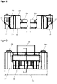
Figur 2 zeigt eine Frontansicht des Transportgestells 10 ausFigur 1 . Ersichtlich befinden sich zwei erste Einfahröffnungen 12 a in einem unteren Bereich des Transportgestells. Zwei zweite Einfahröffnungen 12 b sind von den zwei ersten Einfahröffnungen 12 a durch die Materialbrücken 24 beabstandet. Außerdem sind die Stützabschnitte 20 ebenfalls durch die Materialbrücken 24 voneinander beabstandet. - Die ersten Einfahröffnungen 12 a haben eine Höhe ha und eine Breite I. Die zweiten Einfahröffnungen 12 b weisen eine Höhe hb und beispielhaft, aber nicht einschränkend ebenfalls eine zweite Breite I auf. In der dargestellten Ausführungsform sind außerdem die Höhen ha und hb gleich hoch ausgebildet, was zweckmäßig, aber nicht einschränkend für die Erfindung ist.
- Eine Mindesthöhe der Einfahröffnungen 12 a, 12 b ist durch eine typische Höhe der Zinken eines Flurförderzeugs festgelegt. Typischerweise ist ha bzw. hb größer als 5 cm, bevorzugt zwischen 5 und 15 cm ausgebildet. Die Breite I der Einfahröffnungen 12 ist ebenfalls in Abhängigkeit einer typischen Breite eines Zinkens eines Flurförderzeugs ausgebildet und ist in etwas zwischen 15 cm und 30 cm bevorzugt zwischen 20 und 25 cm, wobei dies nicht einschränkend zu verstehen ist.
- Die Höhe des Transportgestells ist mit dem Bezugszeichen c dargestellt und ist beispielsweise ca. 200 bis 300 mm. Mit c1 ist die Höhe des Transportgestells 10 inklusive der Höhe einer Stapelmimik 26 dargestellt, wobei die Stapelmimik 26 hier in den Eckbereichen des Transportgestells 10 befindliche Nocken umfasst und im Stapel mit einem gleichartig ausgebildeten Transportgestell 10 in entsprechende Ausnahmen eintaucht.
-
Figur 3 zeigt eine Seitenansicht des Transportgestells 10 ausFigur 1 . Der Tragegriff 22 befindet sich in etwa mittig der Seitenwand. Mit d ist eine Breite der Materialbrücke 24 eingezeichnet, welche vorteilhaft in etwa zwischen einem Drittel und der Hälfte einer Breite b des Transportgestells 10 ausgestaltet ist. Diese Bemessung ermöglicht eine stabile Lastenübertragung der punktuell durch die Stapelzinken aufgebrachten Last insbesondere beim Anheben des Transportgestells 10. Weiterhin sind oberseitig wiederrum die erste Stapelmimik 26 a in Form von Noppen sichtbar, welche mit der inFigur 5 dargestellten zweiten Stapelmimik 26 b zusammenwirkt, um ein sicheres Aufeinanderstapeln gleichartiger Transportgestelle 10 zu ermöglichen. -
Figur 4 zeigt eine Schnittansicht durch die inFigur 3 dargestellte Ebene A-A. Insbesondere ist erkennbar, dass das Transportgestell 10 im Gegensatz zu Holzpaletten, beispielsweise Europaletten, nicht massiv ausgebildet ist, sondern, hier beispielhaft im Bereich der Stützabschnitte 20 und Materialbrücken 24 dargestellt, luftzugängliche Kammern 28 aufweist, welche das Transportgestell 10 sehr leicht machen. -
Figur 5 zeigt eine unterseitige Ansicht des Transportgestells 10 ausFigur 1 . Die Aufstandsfläche 16 ist vollflächig, aber nicht massiv ausgebildet, und weist typische Verstrebungen oder Gitterstrukturen auf, die sich hier beispielsweise im Wesentlichen über die gesamte Unterseite des Transportgestells 10 erstrecken. In alternativen nicht dargestellten Ausführungsformen kann unterhalb der ersten Einfahröffnungen 12 kein Material vorhanden sein. - Weiterhin ist die zweite Stapelmimik 26 b in Form von Aussparungen sichtbar, welche mit der in
Figur 6 dargestellten ersten Stapelmimik 26 a zusammenwirken. -
Figur 6 zeigt eine Draufsicht auf das Transportgestell 10 ausFigur 1 , wobei hier auch die Abmessungen, nämlich die Länge a und die Breite b dargestellt sind. In bevorzugten Ausführungsformen sind zumindest eine der Längen oder Breiten a, b entweder 800 mm oder 1200 mm, und befinden sich also im Modulmaß der Euro-Palette. Weiter bevorzugt ist es, wenn die zweite der Längen oder Breiten a, b ein Bruchteil des Modulmaßes bildet, wobei das Modulmaß ein ganzzeiliges Vielfaches der Länge bzw. Breite a, b ist, insbesondere z.B. 2, 3 oder 4. Auf diese Weise fügt sich das erfindungsgemäße Transportgestell 10 kompatibel in ein bestehendes Poolsystem ein. - Die Erfindung ist nicht auf die den Figuren dargestellten Ausführungsform beschränkt, sondern umfasst eine Vielzahl von möglichen Alternativen, welche im Können des Fachmanns liegen.
- Insbesondere ist die dargestellte Ausführungsform in der Größe von einem Drittel einer Euro-Poolpalette nicht einschränkend zu verstehen, so dass die Erfindung insbesondere auch Transportgestelle mit anderen Außenbemaßungen umfasst.
- 10 Transportgestell; 12 Einfahröffnung; 12a erste Einfahröffnung; 12b zweite Einfahröffnung; 14 Aufnahmefläche; 16 Aufstandsfläche; 18 Seitenwand; 20 Stützabschnitt; 22 Tragegriff; 24 Materialbrücke; 26 Stapelmimik; 26a erste Stapelmimik; 26b zweite Stapelmimik; 28 Kammer; a Länge; b Breite; c Höhe; c1 Höhe mit Stapelmimik; d Breite der Materialbrücke
Claims (10)
- Transportgestell (10) aus einem Kunststoffmaterial mit einer Aufnahmefläche (14) für ein Transportgut, einer Aufstandsfläche (16), vier Seitenwänden (18), und Einfahröffnungen (12) in zumindest einer Seitenwand (18) für die Gabelzinken eines Flurförderzeugs, beispielsweise eines Hubwagens, Gabelstaplers, Radladers oder eines Traktors mit Anbaugerät,
wobei ein Eingriff der Gabelzinken des Flurförderzeugs in zumindest eine erste Einfahröffnung (12a) ein Anheben des Transportgestells (10) mit darauf befindlichem Transportgut ermöglicht und ein Eingriff der Gabelzinken des Flurförderzeugs in zumindest eine zweite Einfahröffnung (12b) ein Abheben auf der Aufnahmefläche (14) angeordneten Transportguts ermöglicht,
dadurch gekennzeichnet, dass die zweite Einfahröffnung (12b) in derselben Seitenwand (18) wie die erste Einfahröffnung (12a) und oberhalb dieser angeordnet ist. - Transportgestell (10) nach Anspruch 1, dadurch gekennzeichnet, dass das Transportgestell (10) zwei nebeneinander angeordnete erste Einfahröffnungen (12a) aufweist.
- Transportgestell (10) nach einem der vorhergehenden Ansprüche, dadurch gekennzeichnet, dass das Transportgestell (10) zwei nebeneinander angeordnete zweite Einfahröffnungen (12b) aufweist.
- Transportgestell (10) nach einem der vorhergehenden Ansprüche, dadurch gekennzeichnet, dass die Einfahröffnungen (12) durch Materialbrücken (24) voneinander beabstandet sind.
- Transportgestell (10) nach einem der vorhergehenden Ansprüche, dadurch gekennzeichnet, dass das Transportgestell (10) Stützabschnitte (20) aufweist, welche die Aufnahmefläche (14) ausbilden.
- Transportgestell (10) nach Anspruch 4 und 5, dadurch gekennzeichnet, dass die Stützabschnitte (20) durch die Materialbrücken (24) miteinander verbunden sind.
- Transportgestell (10) nach einem der vorhergehenden Ansprüche, dadurch gekennzeichnet, dass das Transportgestell (10) Fußabschnitte aufweist, welche die Aufstandsfläche (16) bilden.
- Transportgestell (10) nach einem der vorhergehenden Ansprüche, dadurch gekennzeichnet, dass das Transportgestell (10) in der Aufnahmefläche (14), insbesondere in Eckbereichen der Aufnahmefläche (14), eine erste Stapelmimik (26a) aufweist, und in der Aufstandsfläche (16) eine zweite Stapelmimik (26b) aufweist, welche im Stapel zweier gleich ausgebildeter Transportgestelle (10) zusammenwirken, um ein Gegeneinander-Verrutschen der Transportgestelle (10) zu behindern.
- Transportgestell (10) nach einem der vorhergehenden Ansprüche, dadurch gekennzeichnet, dass das Transportgestell (10) einstückig im Spritzguss erzeugt ist.
- Transportgestell (10) nach einem der vorhergehenden Ansprüche, dadurch gekennzeichnet, dass das Transportgestell (10) in zumindest einer Dimension, bevorzugt in zwei Dimensionen das Modulmaß einer Poolpalette aufweist, insbesondere einer Europoolpalette mit Maßen 1200 mm und/ oder 800 mm nach DIN EN 13698-1 (2009-10).
Applications Claiming Priority (1)
| Application Number | Priority Date | Filing Date | Title |
|---|---|---|---|
| DE102021115700.5A DE102021115700A1 (de) | 2021-06-17 | 2021-06-17 | Transportgestell |
Publications (1)
| Publication Number | Publication Date |
|---|---|
| EP4105137A1 true EP4105137A1 (de) | 2022-12-21 |
Family
ID=82067480
Family Applications (1)
| Application Number | Title | Priority Date | Filing Date |
|---|---|---|---|
| EP22179169.2A Pending EP4105137A1 (de) | 2021-06-17 | 2022-06-15 | Transportgestell |
Country Status (2)
| Country | Link |
|---|---|
| EP (1) | EP4105137A1 (de) |
| DE (1) | DE102021115700A1 (de) |
Citations (10)
| Publication number | Priority date | Publication date | Assignee | Title |
|---|---|---|---|---|
| DE2616456A1 (de) * | 1976-04-14 | 1977-10-27 | Martin Schreiber | Transportplattform |
| JP2000043871A (ja) * | 1998-07-30 | 2000-02-15 | Yoshiko Fujisawa | 合成樹脂製パレット |
| WO2000018651A2 (en) * | 1998-09-30 | 2000-04-06 | Pieter Jacobus Grobler | Pallet with means for facilitating the removal of the load |
| US6112672A (en) * | 1999-05-28 | 2000-09-05 | Burnham Service Company, Inc. | Selectively arrangeable pallet |
| US6644217B1 (en) * | 2002-06-06 | 2003-11-11 | Lyle Meyer | Pallet system and method |
| DE102007054521A1 (de) | 2007-11-06 | 2009-05-14 | Cabka Gmbh | Shuttle-Palette für ein Lagersystem |
| JP2013043674A (ja) * | 2011-08-24 | 2013-03-04 | Takao Ishikawa | パレット |
| EP2583908A1 (de) * | 2011-10-21 | 2013-04-24 | Lapp Engineering & Co. | Lager- und Transportpalette |
| DE202015003069U1 (de) | 2015-04-28 | 2016-04-11 | Ralph Kesting | Transportgestell für stoßempfindliche Bauteile |
| DE102018119699A1 (de) | 2018-08-14 | 2020-02-20 | Schoeller Allibert Gmbh | Palette aus Kunststoff mit einem Oberdeck und einem kufenartigen Unterteil |
Family Cites Families (2)
| Publication number | Priority date | Publication date | Assignee | Title |
|---|---|---|---|---|
| AU2555171A (en) | 1970-02-19 | 1972-08-24 | Imperial Chemical Industries Limited | Improvements in and relating to pallets |
| US9010255B2 (en) | 2012-02-02 | 2015-04-21 | Rehrig Pacific Company | Keg pallet |
-
2021
- 2021-06-17 DE DE102021115700.5A patent/DE102021115700A1/de active Pending
-
2022
- 2022-06-15 EP EP22179169.2A patent/EP4105137A1/de active Pending
Patent Citations (10)
| Publication number | Priority date | Publication date | Assignee | Title |
|---|---|---|---|---|
| DE2616456A1 (de) * | 1976-04-14 | 1977-10-27 | Martin Schreiber | Transportplattform |
| JP2000043871A (ja) * | 1998-07-30 | 2000-02-15 | Yoshiko Fujisawa | 合成樹脂製パレット |
| WO2000018651A2 (en) * | 1998-09-30 | 2000-04-06 | Pieter Jacobus Grobler | Pallet with means for facilitating the removal of the load |
| US6112672A (en) * | 1999-05-28 | 2000-09-05 | Burnham Service Company, Inc. | Selectively arrangeable pallet |
| US6644217B1 (en) * | 2002-06-06 | 2003-11-11 | Lyle Meyer | Pallet system and method |
| DE102007054521A1 (de) | 2007-11-06 | 2009-05-14 | Cabka Gmbh | Shuttle-Palette für ein Lagersystem |
| JP2013043674A (ja) * | 2011-08-24 | 2013-03-04 | Takao Ishikawa | パレット |
| EP2583908A1 (de) * | 2011-10-21 | 2013-04-24 | Lapp Engineering & Co. | Lager- und Transportpalette |
| DE202015003069U1 (de) | 2015-04-28 | 2016-04-11 | Ralph Kesting | Transportgestell für stoßempfindliche Bauteile |
| DE102018119699A1 (de) | 2018-08-14 | 2020-02-20 | Schoeller Allibert Gmbh | Palette aus Kunststoff mit einem Oberdeck und einem kufenartigen Unterteil |
Also Published As
| Publication number | Publication date |
|---|---|
| DE102021115700A1 (de) | 2022-12-22 |
Similar Documents
| Publication | Publication Date | Title |
|---|---|---|
| DE69603881T2 (de) | Stapelbare Palette | |
| DE2554210C2 (de) | Doppeldeckpalette aus Kunststoff | |
| EP0301445A2 (de) | Flachpalette | |
| EP3188975B1 (de) | Ladegutträger | |
| EP0669258B1 (de) | Teilpalette | |
| DE202012008319U1 (de) | Palette zum Transport von Gegenständen mit einem Kunststoffdeck | |
| DE202011105716U1 (de) | Transportsystem für Transportbehälter oder Gitterboxen | |
| DE202012002291U1 (de) | Palette | |
| DE102021115700A1 (de) | Transportgestell | |
| WO2005019048A1 (de) | Nestbarer ladungsträger | |
| DE3819894A1 (de) | Arbeitsverfahren zur lagerung, foerderung und zum transport von waren aller art, sowie ein warentraeger und dessen verwendung | |
| EP1919787A1 (de) | Palette mit hoher formstabilität und tragkraft | |
| DE102005011212A1 (de) | Transport- und Lagergestell | |
| DE3007395A1 (de) | Palette, die aus baulementen zu einer einheit zusammengesetzt ist | |
| DE102021108196A1 (de) | Paletten- oder Ladungsträger für innerbetrieblichen Transport und Lagerung von Waren | |
| DE102006018870B3 (de) | Palette mit hoher Formstabilität und Tragkraft | |
| DE9103462U1 (de) | Kunststoff-Palette | |
| DE102013100449B4 (de) | Flurförderzeug für Paletten | |
| EP3521190A1 (de) | Transportsystem mit palette und plattenelement | |
| DE102008031782B4 (de) | Palette | |
| DE4300672C2 (de) | Transportpalette | |
| DE102018119699A1 (de) | Palette aus Kunststoff mit einem Oberdeck und einem kufenartigen Unterteil | |
| DE2549252A1 (de) | Vorrichtung fuer das umsetzen, den transport und die lagerung von containern und aehnlichen lasten | |
| DE202008005632U1 (de) | Teilpalette | |
| DE9313977U1 (de) | Palette zum Lagern und Transportieren von Gegenständen |
Legal Events
| Date | Code | Title | Description |
|---|---|---|---|
| PUAI | Public reference made under article 153(3) epc to a published international application that has entered the european phase |
Free format text: ORIGINAL CODE: 0009012 |
|
| STAA | Information on the status of an ep patent application or granted ep patent |
Free format text: STATUS: THE APPLICATION HAS BEEN PUBLISHED |
|
| AK | Designated contracting states |
Kind code of ref document: A1 Designated state(s): AL AT BE BG CH CY CZ DE DK EE ES FI FR GB GR HR HU IE IS IT LI LT LU LV MC MK MT NL NO PL PT RO RS SE SI SK SM TR |
|
| STAA | Information on the status of an ep patent application or granted ep patent |
Free format text: STATUS: REQUEST FOR EXAMINATION WAS MADE |
|
| 17P | Request for examination filed |
Effective date: 20230317 |
|
| RBV | Designated contracting states (corrected) |
Designated state(s): AL AT BE BG CH CY CZ DE DK EE ES FI FR GB GR HR HU IE IS IT LI LT LU LV MC MK MT NL NO PL PT RO RS SE SI SK SM TR |
|
| STAA | Information on the status of an ep patent application or granted ep patent |
Free format text: STATUS: EXAMINATION IS IN PROGRESS |
|
| 17Q | First examination report despatched |
Effective date: 20250306 |