EP4102255B1 - Kalibrierung einer lidarsensoranordnung auf der basis einer referenzfläche - Google Patents
Kalibrierung einer lidarsensoranordnung auf der basis einer referenzfläche Download PDFInfo
- Publication number
- EP4102255B1 EP4102255B1 EP22188165.9A EP22188165A EP4102255B1 EP 4102255 B1 EP4102255 B1 EP 4102255B1 EP 22188165 A EP22188165 A EP 22188165A EP 4102255 B1 EP4102255 B1 EP 4102255B1
- Authority
- EP
- European Patent Office
- Prior art keywords
- lidar sensor
- sensor assembly
- light
- assembly
- reference surface
- Prior art date
- Legal status (The legal status is an assumption and is not a legal conclusion. Google has not performed a legal analysis and makes no representation as to the accuracy of the status listed.)
- Active
Links
Images


Classifications
-
- G—PHYSICS
- G01—MEASURING; TESTING
- G01S—RADIO DIRECTION-FINDING; RADIO NAVIGATION; DETERMINING DISTANCE OR VELOCITY BY USE OF RADIO WAVES; LOCATING OR PRESENCE-DETECTING BY USE OF THE REFLECTION OR RERADIATION OF RADIO WAVES; ANALOGOUS ARRANGEMENTS USING OTHER WAVES
- G01S7/00—Details of systems according to groups G01S13/00, G01S15/00, G01S17/00
- G01S7/48—Details of systems according to groups G01S13/00, G01S15/00, G01S17/00 of systems according to group G01S17/00
- G01S7/497—Means for monitoring or calibrating
-
- G—PHYSICS
- G01—MEASURING; TESTING
- G01S—RADIO DIRECTION-FINDING; RADIO NAVIGATION; DETERMINING DISTANCE OR VELOCITY BY USE OF RADIO WAVES; LOCATING OR PRESENCE-DETECTING BY USE OF THE REFLECTION OR RERADIATION OF RADIO WAVES; ANALOGOUS ARRANGEMENTS USING OTHER WAVES
- G01S17/00—Systems using the reflection or reradiation of electromagnetic waves other than radio waves, e.g. lidar systems
- G01S17/02—Systems using the reflection of electromagnetic waves other than radio waves
- G01S17/06—Systems determining position data of a target
- G01S17/08—Systems determining position data of a target for measuring distance only
- G01S17/10—Systems determining position data of a target for measuring distance only using transmission of interrupted, pulse-modulated waves
-
- G—PHYSICS
- G01—MEASURING; TESTING
- G01S—RADIO DIRECTION-FINDING; RADIO NAVIGATION; DETERMINING DISTANCE OR VELOCITY BY USE OF RADIO WAVES; LOCATING OR PRESENCE-DETECTING BY USE OF THE REFLECTION OR RERADIATION OF RADIO WAVES; ANALOGOUS ARRANGEMENTS USING OTHER WAVES
- G01S17/00—Systems using the reflection or reradiation of electromagnetic waves other than radio waves, e.g. lidar systems
- G01S17/02—Systems using the reflection of electromagnetic waves other than radio waves
- G01S17/06—Systems determining position data of a target
- G01S17/42—Simultaneous measurement of distance and other co-ordinates
-
- G—PHYSICS
- G01—MEASURING; TESTING
- G01S—RADIO DIRECTION-FINDING; RADIO NAVIGATION; DETERMINING DISTANCE OR VELOCITY BY USE OF RADIO WAVES; LOCATING OR PRESENCE-DETECTING BY USE OF THE REFLECTION OR RERADIATION OF RADIO WAVES; ANALOGOUS ARRANGEMENTS USING OTHER WAVES
- G01S17/00—Systems using the reflection or reradiation of electromagnetic waves other than radio waves, e.g. lidar systems
- G01S17/88—Lidar systems specially adapted for specific applications
- G01S17/93—Lidar systems specially adapted for specific applications for anti-collision purposes
- G01S17/931—Lidar systems specially adapted for specific applications for anti-collision purposes of land vehicles
Definitions
- LIDAR refers to a technique for measuring distances to visible objects by emitting light and measuring properties of the reflections of the light.
- a LIDAR system has a light emitter and a light sensor.
- the light emitter may comprise a laser that directs highly focused light toward an object which then reflects the light back to the light sensor.
- the light sensor may comprise a photodetector such as a photomultiplier or avalanche photodiode (APD) that converts light intensity to a corresponding electrical signal.
- Optical components such as lenses may be used in the light transmission and reception paths to focus light, depending on the particular nature of the LIDAR system.
- a LIDAR system has signal processing components that analyze reflected light signals to determine the distances to surfaces from which the emitted laser light has been reflected. For example, the system may measure the "time of flight" of a light signal as it travels from the laser, to the surface, and back to the light sensor. A distance is then calculated based on the known speed of light. However, the accuracy of the distance measurement may depend on performance characteristics of the components of the LIDAR system (e.g., power sources, light sources, light sensors, etc.). Additionally, changes in environmental conditions, such as temperature and/or humidity, may impact distance measurements over time.
- JP 2010 203820 A discloses a laser distance measuring instrument including an optical separation part which separates a pulse laser beam from a deflection part into beams for a first route and a second route different in length, when this deflection part is at a predetermined turning position.
- Typical LIDAR systems emit a light pulse and detect reflected light corresponding to the light pulse reflected off an object in the environment. The reflected light signals are then analyzed to determine the distances from the LIDAR system to surfaces from which the emitted laser light has been reflected. For example, the system may measure the "time of flight” (TOF) of a light signal as it travels from the laser, to the object, and back to the light sensor. A distance is then calculated based on the measured time of flight and the known speed of light.
- TOF time of flight
- existing LIDAR systems do not do not take into account performance characteristics of the components of the LIDAR systems.
- these known techniques assume that the light source emits the light pulse substantially instantaneously when it is instructed to fire.
- the light pulse is not emitted instantaneously. Instead, there is some latency inherent in the components of the LIDAR system.
- the light pulse may be Gaussian in nature, ramping up over time to a peak before dropping back off.
- the actual time of flight of the light pulse is a time from a peak of the emitted light pulse to a peak of the return pulse.
- existing LIDAR systems use as a proxy the time at which the light source is instructed to fire.
- existing LIDAR systems do not account for inaccuracies in distance measurements inherently caused by performance characteristics and limitations of the components of the LIDAR systems. Furthermore, existing LIDAR systems do not account for differences in performance characteristics between similar components of the LIDAR system (e.g., differences in characteristics between multiple different light sources within the LIDAR system). Existing LIDAR systems also do not account for changes in performance characteristics over time, such as changes caused by environmental conditions in which the LIDAR systems are operating.
- This application describes techniques for calibrating a LIDAR system based on a reference surface that is fixed at a known distance from a LIDAR sensor assembly.
- the LIDAR sensor assembly is able accurately measure a time of the peak of the emitted light pulse. In some examples this can be done directly by calculating an expected time of flight of a light pulse to the reference surface and back to the LIDAR sensor assembly. From this expected time of flight, the LIDAR sensor assembly can accurately determine a latency from the instruction to fire the light source to the peak of the emitted light pulse that is attributable to the performance characteristics of the components of the LIDAR sensor assembly.
- the time of flight of the light pulse to the reference surface may be negligible, and the LIDAR sensor assembly may determine the latency to be a time from the signal to fire the light source to receipt of the peak return signal.
- the LIDAR sensor assembly can be calibrated to account for the latency, thereby improving the accuracy of subsequent distance measurements.
- these calibration techniques can be performed for each channel (e.g., light source and light sensor combination) of the LIDAR sensor assembly.
- these techniques can be applied at runtime to account for changes in performance characteristics over time, such as changes caused by environmental conditions in which the LIDAR sensor assembly is operating.
- the intensity of the reflected light returned from the reference surface may be measured and compared to previous returns to detect changes in performance of the light sources (e.g., determine degradation, burnout, or malfunction of a light source, storage capacity of a capacitor or other power source, or the like).
- a LIDAR sensor assembly usable to implement the techniques described herein includes a rotatable assembly including one or more light sources.
- the Lidar sensor includes further one or more light sensors, and associated circuitry mounted in a chassis that rotates about a vertical rotational axis to scan horizontally across a scene. During a rotation of the chassis, light pulses are emitted at different horizontal directions. The horizontal angle of light emission varies with the rotation of the chassis.
- LIDAR sensor assemblies according to this disclosure may be mounted in different orientations (e.g., may rotate about an axis other than a vertical axis such that the LIDAR sensor assembly scans in a path other than horizontal).
- a view of the LIDAR sensor assembly may be limited or partially obstructed by an opaque object (e.g., by a stationary portion of the LIDAR sensor assembly, a vehicle to which the LIDAR sensor assembly is mounted, etc.).
- the LIDAR sensor assembly may be said to have a "limited detection angle" of less than 360 degrees.
- the obstruction may include a reference surface that is fixed relative to an axis of rotation of the rotatable assembly. Thus, the reference surface is positioned at a known, fixed distance from the light sources and light sensors of the LIDAR sensor assembly and may be used to calibrate the LIDAR sensor assembly.
- the LIDAR sensor assembly may have an unobstructed 360-degree detection angle.
- the LIDAR sensor assembly may additionally or alternatively include a substantially transparent surface (e.g., a cover or lens surrounding the rotatable assembly).
- the substantially transparent surface may be coupled to a stationary portion of the LIDAR sensor assembly and may be fixed at a known distance from the axis of rotation of the rotatable assembly.
- the substantially transparent surface may reflect a portion of the light emitted by the light source and may, therefore, additionally or alternatively serve as a fixed reference surface from which to calibrate the LIDAR sensor assembly.
- the calibration may be performed by a controller of the LIDAR sensor assembly as follows.
- the controller may cause the light source to emit a pulse of light toward the fixed reference surface.
- the controller then receives a signal from the light sensor indicating detection of reflected light corresponding to reflection of the pulse of light from the fixed reference surface.
- the controller may calibrate the LIDAR sensor assembly based at least in part on the signal indicating detection of the reflected light corresponding to reflection of the pulse of laser light from the fixed reference surface.
- the LIDAR sensor assembly can be calibrated to account for latency inherent in the performance characteristics of the light sources, light sensors, and associated circuitry, thereby improving the accuracy of subsequent distance measurements.
- each channel e.g., light source and light sensor combination
- This calibration can be performed when the LIDAR system is turned on and/or periodically during use to account for changes in performance characteristics over time, such as changes caused by environmental conditions in which the LIDAR sensor assembly is operating.
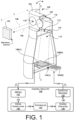
- FIG. 1 is a partial cutaway view of an example system including a LIDAR sensor assembly 100.
- the LIDAR sensor assembly 100 includes a chassis 102 that comprises multiple laser light source(s) 104(1)-104(N) (collectively referred to as “laser light sources 104) and one or more light sensor(s) 106(1)-106(N) (collectively referred to as "light sensors 106"), where N is any integer greater than or equal to 1.
- the LIDAR sensor assembly 100 also includes control circuitry 108 configured to control emission of light by the light sources and to receive and analyze signals from the light sensors 106.
- the chassis 102 may include a partition 110 (shown as transparent for ease and clarity of installation) that forms a compartment on each of two lateral sides of the chassis 102.
- a sensor compartment 112 is shown on one side of the chassis 102 and an emitter compartment 114 is shown on the other side of the chassis 102.
- the sensor compartment 112 houses the light sensor(s) 106 and the emitter compartment 114 houses the laser light source(s) 104 while the partition 110 may be opaque to prevent or limit light leakage therebetween.
- the chassis 102 also supports a first lens 116 and a second lens 118, which may each be mounted so that their optical axes are oriented generally perpendicular to an outer surface of the chassis 102.
- the first lens 116 is generally above the emitter compartment 114 and forward of the laser light source(s) 104.
- one or more mirrors 120 are positioned within the chassis 102 behind the first lens 116 and second lens 118 to redirect emitted and received light between horizontal and vertical directions.
- the chassis 102 may be rotatable about an axis of rotation X, such that as the chassis 102 is rotated, the optical axes of the first lens 116 and the second lens 118 will scan horizontally across a scene including one or more objects including an object 122.
- the LIDAR assembly 100 may include a plurality of channels by which a laser light sources 104 may emit light along a precise direction so that the reflected light strikes a light sensor that corresponds specifically to the laser light source 104.
- laser light source 104(1) and light sensor 106(1) may correspond specifically to a first channel whereas laser light source 104(N) and light sensor 106(N) may correspond specifically to an N-th channel.
- the optical system of the LIDAR sensor assembly 100 is designed so that beams from light sources 104 at different physical positions within the LIDAR sensor assembly 100 are directed outwardly at different angles in azimuth and elevation.
- the first lens 116 is designed to direct light from the light sources 104 for at least some of the channels at different angles relative to the horizon.
- the first lens 116 is designed so that the corresponding light sensor 106 of the channel receives reflected light from the same direction.
- the control circuitry 108 includes a controller 124 that implements control and analysis logic.
- the controller 124 may be implemented in part by an FPGA (field-programmable gate array), a microprocessor, a DSP (digital signal processor), or a combination of one or more of these and other control and processing elements, and may have associated memory for storing associated programs and data.
- FPGA field-programmable gate array
- DSP digital signal processor
- the controller 124 implements control and analysis logic for each of the multiple channels. To initiate a single distance measurement using a single channel, the controller 124 generates a signal 126.
- the signal 126 is received by a charge circuit 128, which determines an appropriate charge duration (e.g., based on desired intensity, pulse width, etc.) and provides signal 130 to charge a capacitive driver 132 for the specified charge duration.
- the capacitive driver 132 comprises a bank of one or more capacitors to drive the light sources 104. The duration of charge determines the intensity of the light pulse emitted for by the light source 104.
- the controller 124 causes the capacitive driver 132 to output an emitter drive signal 134 to the respective light source 104.
- the emitter drive signal 134 causes the respective light source (e.g., light source 104(1) in this example) to light source 104 to emit one or more laser light pulses through the first lens 116 along an outward path 136 (shown by the dot-dash line).
- the burst is reflected by the object 122 in the scene, through the lens second 118, and to the light sensor 106 of the corresponding channel (e.g., light sensor 106(1) in this example) along a return path 138 (shown by the double-dot-dash line).
- the light sensor 106(1) Upon receipt of the reflected light along return path 138, the light sensor 106(1) outputs a return signal 140 to an analog to digital converter (ADC) 142.
- ADC analog to digital converter
- the return signal 140 is generally of the same shape as the emitter drive signal 134, although it may differ to some extent as a result of noise, interference, cross-talk between different emitter/sensor pairs, interfering signals from other LIDAR devices, pulse stretching, and so forth.
- the return signal 140 will also be delayed with respect to the emitter drive signal 134 by an amount of time corresponding to the round-trip propagation time of the emitted laser burst (i.e., the time of flight of the emitted burst).
- the ADC 142 receives and digitizes the return signal 140 to produce a digitized return signal 144.
- the digitized return signal 144 is a stream of digital values indicating the magnitude and timing of the digitized return signal 144 over time.
- the digitized return signal 144 is provided to a cross-correlator 146, which correlates a specific digitized return signal 144 with the corresponding emitter drive signal 134 and outputs a time of flight signal 148 indicative of a time shift from emission of the light pulse by the light source to detection of the reflection of the return of the light pulse at the light sensor.
- the some or all of the functions of the cross-correlator 146 may be performed by the controller 124.
- the controller 124 can then use the time of flight of the pulse of light in combination with the known speed of light to calculate a distance D to the object 122. While the distance D is depicted in this figure as just a distance between the first lens 116 and the object 122, in practice the distance D may take into account a total roundtrip distance of the light path from the light source 104 to the light sensor 106 (i.e., including the distances between the light sources 104 and light sensors 106 and their respective lenses 116 and 118). The foregoing example is just one of many techniques that may be used to recover the time of flight of the emitted pulse.
- the object 122 may serve as a reference surface and may be used to calibrate the LIDAR sensor assembly 100 as described further with reference to FIG. 3 below. That is, the time of flight signal 148 while the while the LIDAR assembly is aimed at the reference surface (i.e., object 122) can be used as a "reference signal" against which to calibrate the LIDAR sensor assembly 100.
- the reference signal (i.e., time of flight signal 148 while the LIDAR assembly is aimed at the reference surface (i.e., object 122)) may be captured uniquely for each channel in the LIDAR sensor assembly 100, may be stored and used for multiple subsequent measurements, and may be updated over time to account for thermal drift and/or other variables.
- the reference signal may be updated at least once per revolution of the chassis. In other examples, the reference signal may be updated more or less frequently. Furthermore, in some examples, multiple readings may be performed and averaged to create the reference signal.
- the object 122 can be used as a reference surface.
- the object 122 may be part of the LIDAR sensor assembly 100 (e.g., a support surface, part of the housing, a lens, etc.), while in other examples, the object 122 may be part of a surrounding environment (e.g., a vehicle, machine, or other structure) which is fixed relative to the LIDAR sensor assembly 100.
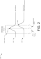
- FIG. 2 is a timing diagram to illustrate calibration of a LIDAR sensor assembly such as that shown in FIG. 1 .
- FIG. 2 is described in the context of the LIDAR sensor assembly 100 of FIG. 1 .
- the concepts illustrated in FIG. 2 are not limited to performance by the LIDAR sensor assembly 100 and may be employed using other systems and devices.
- FIG. 2 depicts an example for a single pulse on a single channel of a LIDAR system. However, in other examples, this technique may be performed for each channel of a LIDAR system, and may be performed multiple times and/or using multiple pulses.
- the timing diagram 200 includes a waveform 202 representing a pulse emitted by an example LIDAR sensor assembly and a waveform 204 representing a received pulse corresponding to the emitted light reflected off of a fixed reference surface.
- the emitter drive signal 134 may be used as the waveform 202 representing the emitted pulse
- the return signal 140 may be used as the waveform 204 representing a received pulse corresponding to light reflected off of a fixed reference surface.
- T 0 corresponds to a time at which the capacitive driver 132 issues the emitter drive signal 134 to cause the light source 104(1) to fire (i.e., the time at which the signal is transmitted).
- the light pulse is not emitted instantaneously. Rather, when the emitter drive signal 134 is applied to the light source 104(1), the light source 104(1) emits a Gaussian pulse that ramps up over time to a peak before dropping back off.
- T 1 corresponds to the peak of the emitted light pulse
- T 2 corresponds to the peak of the return signal.
- the expected time of flight of the light pulse is equal to a time between the peak of the emitted pulse T 1 and the peak of the received pulse T 2 . That is, expected time of flight equals T 2 - T 1 .
- the time corresponding to the peak of the emitted light pulse T 1 may not be known or directly measurable.
- the LIDAR sensor assembly 100 may determine a measured time of flight between transmission of the firing signal T 0 and the peak of the received pulse T 2 . That is, the measured time of flight equals T 2 - T 0 . Then, unlike conventional systems, the LIDAR sensor assembly 100 can compute T 1 based on the received pulse from the reference surface.
- the LIDAR sensor assembly 100 can compute the expected time of flight (i.e., the amount of time it should take the emitted pulse to complete the round trip to the reference surface and back). From this, the LIDAR sensor assembly 100 can compute the time corresponding to the peak of the emitted light pulse T 1 . This also allows, the LIDAR sensor assembly 100 to determine a firing latency (i.e., an amount of time from issuance of the firing signal T 0 to the peak of the emitted light pulse T 1 ) attributable to performance characteristics and limitations of the components of the LIDAR systems, such as the capacitive drivers 132 and the light sources 104.
- a firing latency i.e., an amount of time from issuance of the firing signal T 0 to the peak of the emitted light pulse T 1
- the time of flight of the light pulse to the reference surface may be negligible (i.e., T 2 - T 1 may be negligible) when compared with time of flight of light pulses emitted in the detection angle of the LIDAR sensor assembly (i.e., pulses emitted into the surroundings of the LIDAR sensor assembly to detect objects in the surroundings), which are typically in the range of about 1 meter to about 100 meters from the LIDAR sensor assembly.
- the LIDAR sensor assembly 100 may treat the firing latency to be a whole period from the signal to fire T 0 to receipt of the peak return signal T 2 .
- the LIDAR sensor assembly 100 may determine when the chassis 102 is oriented to emit light toward the reference surface 122 based on the return signals (e.g., the shortest return signal received during each revolution may be determined to correspond to the reference surface).
- a portion of the rotation of the chassis 102 during which pulses are emitted toward the reference surface 122 may be defined as a reference angle, and a rotary encoder coupled to the chassis 102 may be used to indicate when the chassis 102 is oriented to emit light within the reference angle.
- Return signals received while the chassis 102 is oriented in the reference angle may be determined to correspond to the reference surface.
- the intensity of the reflected light returned from the reference surface may be measured and compared to previous returns to detect changes in performance of the light sources (e.g., determine degradation, burnout, or malfunction of a light source, storage capacity of a capacitor or other power source, or the like). For instance, if the peak of the received reference pulse has a magnitude lower than previous received reference pulses, or if a sequence of received reference pulses shows a downward trend of peak values, the LIDAR sensor assembly 100 may determine that the light source corresponding to the emitted pulse is burning out, is damaged, is dirty, or is otherwise in need of service.
- the shape of the return pulse may additionally or alternatively be measured.
- the shape of the return pulse may provide additional information which may be useful for calibration of the LIDAR sensor and/or correlation of emitted and received signal pulses, for example.
- FIGS. 3A, 3B , 4A, and 4B illustrate an example LIDAR sensor assembly 300 with one or more integral reference surfaces.
- FIG. 3A is a perspective view of the example LIDAR sensor assembly 300 with an outer housing omitted for clarity.
- FIG. 3B is a simplified top view of the example LIDAR sensor assembly 300, with a top support rib omitted.
- FIG. 4A is a perspective view of the example LIDAR sensor assembly 300 showing the outer housing.
- FIG. 4B is a simplified cross sectional view of the example LIDAR sensor assembly 300, taken along line B-B of FIG. 4A .
- FIG. 3A illustrates the LIDAR sensor assembly 300 including a stationary portion 302 and a rotatable assembly 304 coupled to, and rotatable relative to, the stationary portion 302.
- the rotatable assembly 304 includes an elongated chassis 306 which houses multiple laser light sources to emit laser light, multiple light sensors, and associated circuitry and electronics (e.g., one or more controllers, charge circuits, capacitive drivers, ADCs, cross correlators, etc.), such as those shown in FIG. 1 .
- the elongated chassis 306 has a generally frustum shape, which tapers from a top end to a bottom end.
- the elongated chassis 306 has an axis of rotation X substantially at a radial center of the frustum, about which the rotatable assembly 304 rotates.
- a lens assembly 308 includes a first lens 310 positioned in an optical path of the laser light sources, and a second lens 312 positioned in an optical path of the light sensors.
- the first lens 310 and the second lens 312 each constitute less than a full circle such that portions of the circumferences of the lenses that are closest together are truncated so they can be closer together.
- centers of the first lens 310 and the second lens 312 are less than one diameter apart from each other.
- one or both lenses may be circular, such as the example shown in FIG. 1 .
- the stationary portion 302 includes an elongated spine 314 which extends substantially parallel to the axis of rotation X of the rotatable assembly 304.
- the spine 314 may include mounting features (e.g., through holes, connectors, brackets, etc.) to mount the LIDAR sensor assembly 300 to a vehicle, machine, or other surface during operation.
- the spine 314 may additionally house electronics and/or provide a routing pathway to route conductors to transfer power and/or data between the LIDAR sensor assembly and a computing device.
- a pair of support ribs 316 extend substantially perpendicularly from the spine 314 and couple to first and second ends of the elongated chassis 306.
- a first support rib 316A extends substantially perpendicularly from the spine 314 and couples to a first (top) end of the chassis 306, and the second support rib 316B extends substantially perpendicularly from the spine 314 and couples to a second (bottom) end of the chassis 306.
- the support ribs 316 are coupled to the chassis 306 by bearings, bushings, or other rotatable connections allowing the chassis 306 to rotate relative to the support ribs 316 and spine 314.
- a motor 318 e.g., an electric motor
- the motor 318 may be located in other locations.
- the motor may be located on an opposite side of the support rib 316A from the chassis 306.
- the motor 318 may be located remotely from the chassis 306 and torque from the motor 318 may be provided by a device for transmitting torque, such as, for example, one or more gears, one or more shafts, one or more belts, and/or one or more chain drives.
- the motor 318 may be located at the second (bottom) end of the chassis 306, for example, between the support rib 316B and the chassis 306, or on the opposite side of the support rib 316B from the chassis 306.
- the spine 314 is opaque and extends substantially parallel to the axis of rotation X of the rotatable assembly 304, the spine 314 obstructs a portion of a scan path of the laser light sources and limits a detection angle of the LIDAR sensor assembly 300.
- a limited detection angle for a LIDAR sensor is undesirable.
- the LIDAR sensor assembly 300 described in this example can take advantage of this limited detection angle by using the spine 314, which is located at a known distance relative to the rotatable assembly 304, as a fixed reference surface in order to calibrate the LIDAR sensor assembly according to the techniques described herein.
- FIG. 3B illustrates the limited detection angle of the LIDAR sensor assembly 300.
- the detection angle of the LIDAR sensor assembly 300 is indicated by the angle ⁇ .
- the LIDAR sensor assembly 300 emits laser light into a scene surrounding the LIDAR sensor assembly 300 to detect objects in the scene.
- the spine 314 obstructs the laser light.
- the angle ⁇ that is obstructed by the spine 314 depends on the width of the spine, the distance of the spine 314 from the axis of rotation X, the spacing of the optical axes of the first lens 310 and the second lens 312. In the illustrated example, the angle ⁇ is about 270 degrees.
- the angle ⁇ may be between about 240 degrees and about 300 degrees. However, in other examples, the angle ⁇ may be greater than or less than those listed. For instance, in the case of a nose mounted LIDAR sensor assembly ⁇ may be about 180 degrees, while in a top mounted LIDAR assembly ⁇ may be 360 degrees (as will be discussed further with respect to FIG. 5 ).
- the LIDAR sensor assembly 300 may emit one or more pulses of light.
- FIG. 3B illustrates a single emitted pulse of light shown by the dashed line 320.
- the LIDAR sensor assembly may fire multiple pulses of light from multiple different light sources as the sensor rotates through angle ⁇ . Due to the relative proximity of the of the spine 314 to the rotatable assembly 304, parallax may result in the emitted light pulse 320 from being reflected back at an angle that would not ordinarily be incident on the lens 312 and would, therefore, not be detected by the corresponding light sensor within the chassis 306.
- a light diffuser 322 may be disposed on at least a portion of a surface of the spine 314 closest to the rotatable assembly 304.
- the light diffuser 322 may be formed integrally with the spine 314 or may be applied to all or a portion of the spine 314 (e.g., as a cover, sticker, paint, or coating).
- the diffuser 322 provides substantial internal reflection, such that when hit with light at any location on its surface, the diffuser emits light from substantially its entire surface, as shown by the dot dash lines 324 in FIG. 3B .
- the diffuser 322 can comprise any material capable of providing the desired internal reflection such as, for example, a retroreflector, a white or reflective material having a textured surface (e.g., bead blasted glass or acrylic, acid etched glass, etc.), etc.
- a retroreflector e.g., a white or reflective material having a textured surface (e.g., bead blasted glass or acrylic, acid etched glass, etc.), etc.
- a controller of the LIDAR sensor assembly causes a light source to emit a pulse of laser light toward the reference surface (i.e., anywhere within angle ⁇ )
- a signal is received from the light sensor indicating detection of reflected light corresponding to reflection of the pulse of laser light from the fixed reference surface.
- the controller is able to calibrate the LIDAR sensor assembly 300 to account for performance characteristics of the light sources, drivers of the light sources, and other components of the LIDAR sensor assembly 300.
- the LIDAR sensor assembly 300 may also include an outer housing, such as the one shown and described with reference to FIGS. 4A and 4B below.
- the outer housing may include a substantially transparent ring lens through which light is emitted from and received by the LIDAR sensor assembly 300.
- the inclusion of the outer housing, including the ring lens, does not substantially change the operation of the LIDAR sensor assembly provided above.
- the ring lens may be made of an antireflective material and/or interior and exterior surfaces of the ring lens may be coated with an antireflective coating in order to minimize the optical effects of the ring lens on the light entering and exiting the LIDAR sensor assembly 300.
- FIG. 4A is a perspective view of the example LIDAR sensor assembly 300, showing an outer housing 400 to cover and protect the rotatable assembly 304 and the electronics of the LIDAR sensor assembly 300.
- the outer housing 400 includes an opaque cap 402 and main body 404, and a substantially transparent ring lens 406 interposed between the cap 402 and the main body 404.
- the cap 402 is disposed at and covers the first support rib 316A and the first end (the top) of the rotatable assembly 304 of the LIDAR sensor assembly 300.
- the main body 404 surrounds and encloses the second support rib 316B and the second end (bottom) of the rotatable assembly 304.
- the ring lens 406 encircles the portion of the rotatable assembly 304 through which light enters and exits the lens assembly 308.
- the ring lens 406 facilitates the passage of light to and from the LIDAR sensor assembly 300 as the rotatable assembly 304 rotates within the outer housing 400.
- the outer housing 400 encloses the rotatable assembly 304 and is coupled to the stationary portion 302 of the LIDAR sensor assembly 300.
- the cap 402 and the main body 404 are contoured to generally conform to an outer geometry of the rotatable assembly 304 around a majority of its circumference, before curving at an edge closest to the spine 314 to mate with lateral edges of the spine 314.
- Contoured trim pieces 408 may be included to fill a gap between the ring lens 406 and the spine 314 and to match the contours of the cap 402 and the main body 404.
- the contoured trim pieces 408 may be opaque or transparent.
- One or more O-rings (not shown) may be provided at the interfaces between the cap 402 and the ring lens 406, and/or between the ring lens 406 and the main body 404, in order to prevent dirt and moisture from entering the outer housing 400.
- Gaskets and/or sealants may be provided between the outer housing 400 and the spine 314 in order to prevent dirt and moisture from entering the outer housing 400.
- FIG. 4B is a simplified cross sectional view of the example LIDAR sensor assembly 300, taken along line B-B of FIG. 4A.
- FIG. 4B is similar to the example described with reference to FIG. 3B except that in this case, instead of (or in addition to) the spine 314, the ring lens 406 serves as the fixed reference surface for calibrating the LIDAR sensor assembly. Like the spine 314, the ring lens 406 is fixed a known distance from the rotatable assembly 304 and can also serve as a reference surface. Just as in FIG. 3B , for ease of illustration a single pulse of light, shown by the dashed line 320, is emitted from the rotatable assembly 304.
- the LIDAR sensor assembly may fire multiple pulses of light from multiple different light sources.
- at least a portion of the pulse of light is reflected by the ring lens 406.
- an interior surface of the ring lens 406 may not be coated with an antireflective material.
- the reflected portion of the light pulse is shown by the dot dash lines.
- At least some of the reflected light enters the lens 312 and is received by a light sensor of the LIDAR sensor assembly 300.
- the light sensor Upon receipt of the reflected light, the light sensor generates a signal indicating detection of the reflected light corresponding to reflection of the pulse of laser light from the fixed reference surface (the ring lens 406 in this example). Based on this return signal from the reference surface and the known distance to the reference surface, the controller is able to calibrate the LIDAR sensor assembly 300 to account for performance characteristics of the light sources, drivers of the light sources, and other components of the LIDAR sensor assembly 300.
- the calibration operation is not necessarily limited to a portion of the rotation during which the scan direction of the rotatable assembly 304 is directed toward the spine 314. Because a portion of each emitted light pulse is reflected by the ring lens 406 and detected by the light sensors, the LIDAR sensor assembly 300 could be calibrated based on any emitted light pulse emitted at any angle of rotation of the rotatable assembly 304, not necessarily when oriented toward the spine 314. However, in some examples, it may be beneficial to calibrate the LIDAR sensor assembly 300 based on pulses emitted toward the spine 314 since the system need not be simultaneously determining a distance to an object in the surroundings (since the distance to the spine is known).
- the spine 314 may include an optically black portion 410 (or substantially light absorbing portion).
- the surface of the spine 314 may be made optically black by, for example, constructing all or a portion of the spine of an optically black material, or by applying an optically black cover, sticker, paint, or other coating.
- the optically black portion 410 pulses of light incident on the optically black portion 410 will be absorbed and will not be reflected.
- the LIDAR sensor assembly 300 is calibrated based on pulses emitted toward the spine 314, the only return will be the reflections from the ring lens 406.
- the return from the ring lens 406 as the reference surface may be measured during the calibration, and may be filtered out of subsequent distance measurements (i.e., during the portion of the rotation not obstructed by the spine).
- the LIDAR sensor assembly 300 receives multiple returns for every light emission (e.g., one or more reflections from the ring lens 406 as well as desired returns from actual objects in the surrounding scene).
- the reflections from the ring lens 406 are extraneous noise that can degrade the accuracy of the LIDAR sensor assembly.
- the return signals corresponding to reflections the ring lens 406 can be isolated and filtered out, thereby eliminating noise from the return signal and further improving accuracy of the LIDAR sensor assembly 300.
- FIG. 5 is a simplified cross sectional view of another example LIDAR sensor assembly 500 that has an unobstructed 360-degree detection angle.
- FIG. 5 is similar to the example of FIG. 4B , except that the spine 314 and at least one of the support ribs 316A and/or 316B is omitted.
- the LIDAR sensor assembly 500 is supported entirely by an axle 502 extending from a top or a bottom of the LIDAR sensor assembly 500.
- the detection angle of the LIDAR sensor assembly 500 is unobstructed and the LIDAR sensor assembly 500 has a full 360-degree detection angle.
- the LIDAR sensor assembly 500 may still employ the ring lens 406 as a reference surface for calibration according to the techniques described above.
- FIGS. 6 illustrates an example system 600 including a multiple LIDAR sensor assemblies 602A-602F (referred to collectively as "LIDAR sensor assemblies 602") mounted to a vehicle 604.
- the vehicle 604 in this example is illustrated as being an autonomous passenger vehicle.
- LIDAR assemblies can be mounted to non-passenger vehicles, robots, aircraft, and other vehicles, and may be autonomous, semi-autonomous, or human driven.
- FIG. 6 illustrates four corner mounted LIDAR sensor assemblies 602A-602D, a top mounted LIDAR sensor assembly 602E, and a nose mounted LIDAR sensor assembly 602F.
- the corner mounted LIDAR sensor assemblies 602A-602D may be the same as or similar to those shown in FIGS. 3A, 3B , 4A , and/or 4B, for example, and may have a detection angle ⁇ 1 of at least about 240 degrees and at most about 270 degrees.
- the top mounted LIDAR sensor assembly 602E may be the same as or similar to that shown in FIG. 5 , for example, and may have a detection angle ⁇ 2 of about 360 degrees.
- the nose mounted LIDAR sensor assembly 602F may be similar to those shown in FIGS.
- the system 600 may include all of the illustrated LIDAR sensor assemblies 602, a subset of the LIDAR sensor assemblies (e.g., only the corner mounted LIDAR sensor assemblies 602A-602D), or the system 600 may include additional LIDAR sensor assemblies (e.g., a tail mounted LIDAR assembly, side or door mounted LIDAR sensor assemblies, etc.).
- the LIDAR sensor assemblies 602 may be coupled to one or more body panels or structural members of the vehicle 604 or may be formed integrally with the vehicle body itself (e.g., the LIDAR sensor assembly housing may be formed into the contour of a fender, hood, bumper, door, roof, or other portion of the vehicle body).
- a portion of the vehicle body may be within a detection angle of a LIDAR sensor assembly 602.
- the LIDAR sensor assembly may be fixed relative to the portion of the vehicle and, thus, the portion of the vehicle body may serve as a fixed reference surface and may be used for calibration of the LIDAR sensor assembly according to the techniques described herein.
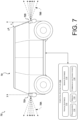
- FIG. 7 is a side view of an example system 700 including a multiple LIDAR sensor assemblies 702A and 702B (referred to collectively as "LIDAR sensor assemblies 702") mounted to a vehicle 704 at different orientations.
- the system 700 includes a first LIDAR sensor assembly 702A mounted at a front corner of the vehicle 704.
- the first LIDAR sensor assembly 702A is mounted such that an axis of rotation X of the first LIDAR sensor assembly 702A is oriented substantially vertically (i.e., normal to the horizon).
- the first LIDAR sensor assembly 702A is configured such that a pattern of emitted light pulses 706A is spanning the horizon, with some pulses being angled above the horizon and some pulses that are below the horizon. In some examples, the pattern of emitted light pulses may be concentrated around the horizon with fewer pulses emitted at angles further from the horizon. However, other scan patterns are also contemplated having light pulses emitted at other angles relative to the
- the second LIDAR sensor assembly 702B is mounted such that an axis of rotation X of the first LIDAR sensor assembly 702B is offset by angle ⁇ relative to vertical (i.e., is tilted at an oblique angle from normal to the horizon). Nevertheless, the second LIDAR sensor assembly 702B is configured such that a pattern of emitted light pulses 706B is substantially the same as that of LIDAR sensor assembly 702A. This may be achieved, for example, by angling one or more mirrors in the LIDAR sensor assembly. However, again, other scan patterns are also contemplated having light pulses emitted at other angles relative to the horizon.
- different LIDAR sensor assemblies of the vehicle 704 may have different scan patterns. For instance, some LIDAR sensor assemblies (e.g., corner mounted LIDAR sensor assemblies) may have scan patterns centered around the horizon, while one or more other LIDAR sensor assemblies (e.g., nose or tail mounted LIDAR sensor assemblies) may have scan patterns oriented below the horizon (e.g., to detect objects closer to a front of the vehicle). These and other variations of mounting configurations are contemplated for LIDAR sensor assemblies according to this disclosure.
- FIG. 7 also illustrates an example computing architecture 708 of the vehicle 704.
- the computing architecture 708 includes one or more sensor systems 710.
- the sensor system(s) 710 include the LIDAR sensor assemblies 702 and may include one or more other sensor systems such as, for example, one or more cameras, radar sensors, microphones, navigation sensors (e.g., GPS, compass, etc.), motion sensors (e.g., inertial sensors, odometers, etc.), and/or environmental sensors (e.g., temperature sensors, pressure sensors, humidity sensors, etc.).
- the sensor system(s) 710 provide input directly to one or more vehicle systems 712.
- the vehicle system(s) 712 may include a vehicle control system to control steering, propulsion, braking, safety systems, and/or communication systems of the vehicle 704. Additionally, in some examples, such as when the vehicle 704 is an autonomous vehicle, the vehicle systems may also include a localizer system to estimate a change in position of the vehicle 704 over time, a perception system to perform object detection and/or classification, and/or a planner system to determine routs and/or trajectories to use to control the vehicle. Additional details of localizer systems, perception systems, and planner systems that are usable can be found in U.S. Patent Application No. 15/281,416, filed September 30, 2016 , entitled "Estimating Friction Based On Image Data".
- Memory 716 is an example of non-transitory computer-readable media.
- Memory 716 may store an operating system and one or more software applications, instructions, programs, and/or data to implement the methods described herein and the functions attributed to the various systems.
- the memory may be implemented using any suitable memory technology, such as static random access memory (SRAM), synchronous dynamic RAM (SDRAM), nonvolatile/Flash-type memory, or any other type of memory capable of storing information.
- SRAM static random access memory
- SDRAM synchronous dynamic RAM
- Flash-type memory any other type of memory capable of storing information.
- the computing architecture 708 also includes one or more communication connections 718 that enable communication by the vehicle with one or more other local or remote computing devices.
- the communications connection(s) 718 include physical and/or logical interfaces for connecting the computing architecture 708 to another computing device or a network.
- the communications connection(s) 718 may enable WiFi-based communication such as via frequencies defined by the IEEE 802.11 standards, short range wireless frequencies such as Bluetooth ® , or any suitable wired or wireless communications protocol that enables the respective computing device to interface with the other computing devices.
- FIG. 8 is a flowchart illustrating an example method 800 of calibrating a LIDAR sensor assembly using a reference surface that is fixed relative to the LIDAR sensor assembly.
- the method 800 is described with reference to the LIDAR sensor assembly of FIG. 1 for convenience and ease of understanding.
- the method 800 is not limited to being performed using the LIDAR sensor assembly of FIG. 1 and may be implemented using any of the other LIDAR sensor assemblies and/or systems described in this application, as well LIDAR sensor assemblies and systems other than those described herein.
- the LIDAR sensor assemblies and systems are not limited to performing the method 800.
- rotatable assembly of a LIDAR sensor assembly such as LIDAR sensor assembly 100 is caused to rotate. This rotation may be caused by a controller (e.g., controller 124 of the LIDAR sensor assembly, a controller of one of vehicle sensor systems 710, etc.).
- the LIDAR sensor assembly scans a detection angle by emitting laser light pulses from one or more light sources (e.g., light sources 104) and receiving reflected returns corresponding to the emitted light pulses by one or more corresponding light sensors (e.g., light sensors 106).
- operation 802 may be initiated upon startup of a vehicle or other machine to which the LIDAR sensor assembly is used.
- the controller of the LIDAR sensor assembly or a controller of a sensor system of a vehicle determines whether to calibrate the LIDAR sensor assembly.
- the controller may be configured to calibrate the LIDAR sensor assembly at least once per revolution of the rotatable assembly.
- the controller may be configured to calibrate the LIDAR sensor assembly every time a light source emits light toward a reference surface.
- the controller may be configured to calibrate the LIDAR sensor assembly periodically (e.g., every M units of time or number of revolutions, where M is any number greater than or equal to 2).
- the controller may be configured to calibrate the LIDAR sensor assembly responsive to occurrence of a triggering event such as powering on the LIDAR sensor assembly, a change in temperature, a difference in measurements by the LIDAR sensor assembly and another LIDAR sensor assembly, detection of an impact or other force exceeding a normal operating conditions, or the like. If the controller determines not to calibrate the LIDAR sensor assembly, the method returns to operation 802 to scan the detection angle of the LIDAR sensor assembly. If, at operation 804, the controller determines to calibrate the LIDAR sensor assembly, the method proceeds to operation 806.
- a triggering event such as powering on the LIDAR sensor assembly, a change in temperature, a difference in measurements by the LIDAR sensor assembly and another LIDAR sensor assembly, detection of an impact or other force exceeding a normal operating conditions, or the like.
- the controller causes a light source of the LIDAR sensor assembly to emit light toward a reference surface that is fixed in relation to the LIDAR sensor assembly.
- the reference surface may comprise a part of the LIDAR sensor assembly as in the example of FIGS. 3A and 4A , a part of a vehicle, machine, or other structure to which the LIDAR sensor assembly is mounted, or any other surface that is fixed at a known distance relative to the LIDAR sensor assembly.
- the controller receives a signal from a light sensor of the LIDAR sensor assembly. The signal received from the light sensor indicates detection of reflected light corresponding to reflection of the pulse of laser light from the reference surface.
- the controller calibrates the LIDAR sensor assembly based at least in part on the signal indicating detection of the reflected light corresponding to reflection of the pulse of laser light from the reference surface.
- the calibration operation 810 includes, at operation 812, measuring a time of flight from a firing signal to fire the pulse of laser light from the laser light source to the detection of the reflected light by the light sensor.
- the controller compares the time of flight to an expected time of flight for the pulse of laser light to travel a known distance from the laser light source to the reference surface and back to the light sensor.
- the controller may adjust a distance calculation based at least in part on the comparison.
- the calibration operation 810 may include other adjustments in addition to or instead of the operations 812-814.
- the calibration operation 810 may include measuring an intensity of a return signal indicating detection of the reflected light corresponding to reflection of the pulse of laser light from the reference surface.
- the measured intensity may be compared to previous returns to detect changes in performance of the light sources (e.g., determine degradation, burnout, or malfunction of a light source, storage capacity of a capacitor or other power source, or the like).
- a drive signal applied to fire the light source may be adjusted (e.g., by adjusting a charge time of one or more capacitive drivers) to adjust an intensity of subsequent light pulses.
- Operations 806-810 are described for a single channel of a LIDAR sensor assembly. For LIDAR sensor assemblies having multiple channels, the operations 806-810 may be performed for each channel of the LIDAR sensor assembly. Moreover, the method 800 describes the process for calibrating a single LIDAR sensor assembly. In LIDAR systems including multiple LIDAR sensor assemblies, the method 800 may be performed for each of the multiple LIDAR sensor assemblies.
- the method 800 is illustrated as a collection of blocks in logical flow graph, which represents sequences of operations that can be implemented in hardware, software, or a combination thereof.
- the blocks represent computer-executable instructions stored on one or more computer-readable storage media that, when executed by one or more processors, perform the recited operations.
- computer-executable instructions include routines, programs, objects, components, data structures, and the like that perform particular functions or implement particular abstract data types.
- the order in which the operations are described is not intended to be construed as a limitation, and any number of the described blocks can be combined in any order and/or in parallel to implement the processes. In some embodiments, one or more blocks of the process may be omitted entirely.
- the method 800 may be combined in whole or in part.
- program modules include routines, programs, objects, components, data structures, etc., and define operating logic for performing particular tasks or implement particular abstract data types.
- software may be stored and distributed in various ways and using different means, and the particular software storage and execution configurations described above may be varied in many different ways.
- software implementing the techniques described above may be distributed on various types of computer-readable media, not limited to the forms of memory that are specifically described.
Landscapes
- Physics & Mathematics (AREA)
- Engineering & Computer Science (AREA)
- Electromagnetism (AREA)
- Computer Networks & Wireless Communication (AREA)
- General Physics & Mathematics (AREA)
- Radar, Positioning & Navigation (AREA)
- Remote Sensing (AREA)
- Optical Radar Systems And Details Thereof (AREA)
- Measurement Of Optical Distance (AREA)
Claims (11)
- Verfahren, das Folgendes umfasst:Übertragen eines Zündsignals zu einer Laserlichtquelle (104) einer LIDAR-Sensorbaugruppe (100), um zu bewirken, dass die Laserlichtquelle Licht zu einer Referenzoberfläche (122) emittiert, die mechanisch mit der LIDAR-Sensorbaugruppe gekoppelt ist, wobei die Referenzoberfläche ein Teil eines stationären Abschnitts (302) der LIDAR-Sensorbaugruppe ist, wobei der stationäre Abschnitt mechanisch mit einer drehbaren Baugruppe (304) gekoppelt ist, die relativ zu dem stationären Abschnitt drehbar ist, und wobei der stationäre Abschnitt dazu konfiguriert ist, stationär zu verbleiben, wenn sich die drehbare Baugruppe dreht, wobei die drehbare Baugruppe die Laserlichtquelle beinhaltet;Empfangen eines Signals von einem Lichtsensor (106) der LIDAR-Sensorbaugruppe; undDetektieren, wenigstens teilweise basierend auf dem empfangenen Signal, von reflektiertem Licht, das einer Reflexion des emittierten Lichts von der Referenzoberfläche entspricht.
- Verfahren nach Anspruch 1, wobei:
der stationäre Abschnitt (302) Folgendes umfasst:eine erste Stützrippe (316A) und eine zweite Stützrippe (316B); undeinen länglichen Rücken (314), der sich zwischen der ersten Stützrippe und der zweiten Stützrippe erstreckt und mit diesen gekoppelt ist, wobei der längliche Rücken als die Referenzoberfläche (122) dient,wobei die drehbare Baugruppe Folgendes umfasst:ein längliches Gehäuse (306) mit einer Rotationsachse, um die die drehbare Baugruppe (304) drehbar ist, unddie erste Stützrippe mit einem ersten Ende des länglichen Gehäuses gekoppelt ist und diezweite Stützrippe mit einem zweiten Ende des länglichen Gehäuses gekoppelt ist. - Verfahren nach einem der vorhergehenden Ansprüche, wobei:der stationäre Abschnitt (302) eine undurchsichtige Oberfläche umfasst, die in wenigstens einem Abschnitt eines Pfades der Laserlichtquelle angeordnet und dazu konfiguriert ist, stationär zu verbleiben, wenn sich die drehbare Baugruppe (304) dreht; unddie undurchsichtige Oberfläche einen Lichtdiffusor (322) umfasst.
- Verfahren nach einem der vorhergehenden Ansprüche, das ferner Durchführen einer Kalibrierung der LIDAR-Sensorbaugruppe (100) wenigstens teilweise basierend auf dem empfangenen Signal umfasst.
- Verfahren nach einem der vorhergehenden Ansprüche, das ferner Wiederholen des Übertragens, des Empfangens und des Detektierens wenigstens einmal pro Umdrehung der drehbaren Baugruppe (304) umfasst.
- Verfahren nach einem der vorhergehenden Ansprüche, wobei das Übertragen, das Empfangen und das Detektieren als Reaktion auf ein Auslöseereignis durchgeführt werden.
- Verfahren nach Anspruch 2, wobei:
der längliche Rücken (314) eine Halterung zum Montieren der LIDAR-Sensorbaugruppe (100) an einem Fahrzeug umfasst. - Verfahren nach einem der Ansprüche 1 oder 2, wobei:der stationäre Abschnitt (302) ein längliches Element umfasst, das als eine undurchsichtige Oberfläche dient, unddie undurchsichtige Oberfläche wenigstens einen Abschnitt einer Halterung für die LIDAR-Sensorbaugruppe (100) umfasst.
- Verfahren nach Anspruch 2, wobei:der stationäre Abschnitt (302) ein längliches Element umfasst; unddas längliche Element im Wesentlichen parallel zu der Rotationsachse des länglichen Gehäuses (306) ist.
- Computerlesbares Medium oder computerlesbare Medien, das bzw. die computerausführbare Anweisungen umfasst bzw. umfassen, die, wenn sie ausgeführt werden, bewirken, dass ein Rechensystem einschließlich einer LIDAR-Sensorbaugruppe das Verfahren nach einem der Ansprüche 1-9 durchführt.
- System, das Folgendes umfasst:eine LIDAR-Sensorbaugruppe (100), die zum Durchführen des Verfahren nach einem der Ansprüche 1 bis 9 konfiguriert ist;die Referenzoberfläche (122) nach einem der Ansprüche 1 bis 9; undeinen oder mehrere Prozessoren und ein oder mehrere computerlesbare Medien, wobei das eine oder die mehreren computerlesbaren Medien computerausführbare Anweisungen umfassen, die, wenn sie ausgeführt werden, bewirken, dass das Rechensystem das Verfahren nach einem der Ansprüche 1-9 durchführt.
Applications Claiming Priority (4)
| Application Number | Priority Date | Filing Date | Title |
|---|---|---|---|
| US201662440761P | 2016-12-30 | 2016-12-30 | |
| US15/487,363 US10359507B2 (en) | 2016-12-30 | 2017-04-13 | Lidar sensor assembly calibration based on reference surface |
| PCT/US2017/068286 WO2018125828A1 (en) | 2016-12-30 | 2017-12-22 | Lidar sensor assembly calibration based on reference surface |
| EP17829895.6A EP3563179B1 (de) | 2016-12-30 | 2017-12-22 | Kalibrierung einer lidarsensoranordnung auf der basis einer referenzfläche |
Related Parent Applications (1)
| Application Number | Title | Priority Date | Filing Date |
|---|---|---|---|
| EP17829895.6A Division EP3563179B1 (de) | 2016-12-30 | 2017-12-22 | Kalibrierung einer lidarsensoranordnung auf der basis einer referenzfläche |
Publications (3)
| Publication Number | Publication Date |
|---|---|
| EP4102255A2 EP4102255A2 (de) | 2022-12-14 |
| EP4102255A3 EP4102255A3 (de) | 2023-03-15 |
| EP4102255B1 true EP4102255B1 (de) | 2025-05-14 |
Family
ID=60991645
Family Applications (2)
| Application Number | Title | Priority Date | Filing Date |
|---|---|---|---|
| EP22188165.9A Active EP4102255B1 (de) | 2016-12-30 | 2017-12-22 | Kalibrierung einer lidarsensoranordnung auf der basis einer referenzfläche |
| EP17829895.6A Active EP3563179B1 (de) | 2016-12-30 | 2017-12-22 | Kalibrierung einer lidarsensoranordnung auf der basis einer referenzfläche |
Family Applications After (1)
| Application Number | Title | Priority Date | Filing Date |
|---|---|---|---|
| EP17829895.6A Active EP3563179B1 (de) | 2016-12-30 | 2017-12-22 | Kalibrierung einer lidarsensoranordnung auf der basis einer referenzfläche |
Country Status (5)
| Country | Link |
|---|---|
| US (2) | US10359507B2 (de) |
| EP (2) | EP4102255B1 (de) |
| JP (1) | JP7086100B2 (de) |
| CN (1) | CN110121660B (de) |
| WO (1) | WO2018125828A1 (de) |
Families Citing this family (54)
| Publication number | Priority date | Publication date | Assignee | Title |
|---|---|---|---|---|
| US12399279B1 (en) | 2016-02-15 | 2025-08-26 | Red Creamery Llc | Enhanced hybrid LIDAR with high-speed scanning |
| US11556000B1 (en) | 2019-08-22 | 2023-01-17 | Red Creamery Llc | Distally-actuated scanning mirror |
| US12123950B2 (en) | 2016-02-15 | 2024-10-22 | Red Creamery, LLC | Hybrid LADAR with co-planar scanning and imaging field-of-view |
| US12399278B1 (en) | 2016-02-15 | 2025-08-26 | Red Creamery Llc | Hybrid LIDAR with optically enhanced scanned laser |
| USD871412S1 (en) * | 2016-11-21 | 2019-12-31 | Datalogic Ip Tech S.R.L. | Optical scanner |
| US10359507B2 (en) | 2016-12-30 | 2019-07-23 | Panosense Inc. | Lidar sensor assembly calibration based on reference surface |
| WO2018157197A1 (en) * | 2017-03-03 | 2018-09-07 | Trent Dutton | A system and methodology for light level audit sampling |
| US10663595B2 (en) * | 2017-03-29 | 2020-05-26 | Luminar Technologies, Inc. | Synchronized multiple sensor head system for a vehicle |
| US10447973B2 (en) * | 2017-08-08 | 2019-10-15 | Waymo Llc | Rotating LIDAR with co-aligned imager |
| US10746858B2 (en) * | 2017-08-17 | 2020-08-18 | Uatc, Llc | Calibration for an autonomous vehicle LIDAR module |
| CN111257843B (zh) * | 2017-10-20 | 2022-08-02 | 深圳市道通科技股份有限公司 | 汽车盲区雷达标定设备 |
| US10852731B1 (en) * | 2017-12-28 | 2020-12-01 | Waymo Llc | Method and system for calibrating a plurality of detection systems in a vehicle |
| CN109031252B (zh) * | 2018-08-22 | 2020-12-18 | Oppo广东移动通信有限公司 | 标定方法、标定控制器及标定系统 |
| JP7162227B2 (ja) | 2018-08-29 | 2022-10-28 | パナソニックIpマネジメント株式会社 | 距離測定装置 |
| JP2020046341A (ja) * | 2018-09-20 | 2020-03-26 | パイオニア株式会社 | 投光装置、投受光装置及び測距装置 |
| KR102028606B1 (ko) * | 2018-11-06 | 2019-10-04 | 한국산업기술시험원 | 광트랩을 이용한 윈드라이다의 교정장치 및 이를 이용한 교정방법 |
| CN109375195B (zh) * | 2018-11-22 | 2019-07-16 | 中国人民解放军军事科学院国防科技创新研究院 | 一种基于正交法向量的多线激光雷达外参数快速标定方法 |
| CN111381219B (zh) * | 2018-12-27 | 2024-09-24 | 余姚舜宇智能光学技术有限公司 | 一种激光发射接收组件以及激光雷达及其系统和扫描方法 |
| JP2020106396A (ja) * | 2018-12-27 | 2020-07-09 | ソニーセミコンダクタソリューションズ株式会社 | 測距装置 |
| US11460578B2 (en) * | 2018-12-28 | 2022-10-04 | Robert Bosch Gmbh | 3D lidar sensing unit with oscillating axis of rotation for autonomous driving |
| US11321873B1 (en) * | 2019-02-04 | 2022-05-03 | Amazon Technologies, Inc. | Calibrating and detecting vibration of stereo ranging systems |
| JP2020134313A (ja) * | 2019-02-20 | 2020-08-31 | 株式会社デンソー | 光検出器 |
| USD957968S1 (en) | 2019-02-20 | 2022-07-19 | Waymo Llc | Sensor housing |
| USD915913S1 (en) | 2019-05-01 | 2021-04-13 | Waymo Llc | Roof pod housing |
| USD950404S1 (en) | 2019-05-01 | 2022-05-03 | Waymo Llc | Roof pod housing |
| USD902756S1 (en) | 2019-02-20 | 2020-11-24 | Waymo Llc | Sensor assembly |
| JP2020134516A (ja) * | 2019-02-20 | 2020-08-31 | 株式会社デンソー | 車両周辺監視システム |
| US11681030B2 (en) | 2019-03-05 | 2023-06-20 | Waymo Llc | Range calibration of light detectors |
| EP3948335A4 (de) * | 2019-03-29 | 2023-04-05 | OMRON Corporation | Abstandsmesssysteme und -verfahren |
| US11603048B2 (en) * | 2019-05-01 | 2023-03-14 | Waymo Llc | Autonomous vehicle roof pod |
| US11964616B2 (en) | 2019-05-01 | 2024-04-23 | Waymo Llc | Autonomous vehicle roof pod |
| CN110333503B (zh) * | 2019-05-29 | 2023-06-09 | 菜鸟智能物流控股有限公司 | 激光雷达的标定方法、装置及电子设备 |
| US11579290B2 (en) | 2019-06-05 | 2023-02-14 | Stmicroelectronics (Research & Development) Limited | LIDAR system utilizing multiple networked LIDAR integrated circuits |
| US11728621B2 (en) | 2019-06-05 | 2023-08-15 | Stmicroelectronics (Research & Development) Limited | Voltage controlled steered VCSEL driver |
| DE102019126336A1 (de) * | 2019-09-30 | 2021-04-01 | Deutsches Zentrum für Luft- und Raumfahrt e.V. | Vorrichtung zur Satelliten-Laserentfernungsmessung und Verfahren zur Satelliten-Laserentfernungsmessung |
| US11738461B2 (en) | 2019-10-18 | 2023-08-29 | Off-World, Inc. | Systems and methods for industrial robotics |
| DE102019216811A1 (de) * | 2019-10-31 | 2021-05-06 | Robert Bosch Gmbh | LIDAR-Sensor mit Kontrolldetektor |
| US11747453B1 (en) | 2019-11-04 | 2023-09-05 | Waymo Llc | Calibration system for light detection and ranging (lidar) devices |
| US10797698B1 (en) | 2019-11-29 | 2020-10-06 | Waymo Llc | Systems and methods for selecting light emitters for emitting light |
| US12085647B2 (en) * | 2019-12-27 | 2024-09-10 | Waymo Llc | LIDAR occlusion detection methods and systems |
| DE102020103794B4 (de) * | 2020-02-13 | 2021-10-21 | Daimler Ag | Verfahren zur Kalibrierung eines Lidarsensors |
| CN113495256B (zh) * | 2020-04-01 | 2024-04-05 | 北京京东乾石科技有限公司 | 确定多个激光雷达之间标定结果的准确度的方法和装置 |
| EP3943977B1 (de) * | 2020-07-20 | 2024-09-04 | Infineon Technologies AG | Vorrichtung mit einem laufzeitsensor und verfahren zur charakterisierung eines laufzeitsensors |
| US11982772B2 (en) * | 2020-08-25 | 2024-05-14 | Pony Ai Inc. | Real-time sensor calibration and calibration verification based on statically mapped objects |
| US11656326B2 (en) | 2020-09-21 | 2023-05-23 | Argo AI, LLC | Radar elevation angle measurement |
| US12306299B2 (en) * | 2021-01-22 | 2025-05-20 | GM Global Technology Operations LLC | LIDAR laser health diagnostic |
| CN112882000B (zh) * | 2021-02-05 | 2023-02-03 | 北京科技大学 | 一种激光雷达的自动标定方法 |
| DE102021204330A1 (de) | 2021-04-30 | 2022-11-03 | Robert Bosch Gesellschaft mit beschränkter Haftung | Verfahren zur Überwachung einer Winkelposition eines LiDAR-Systems |
| TWI768923B (zh) * | 2021-05-24 | 2022-06-21 | 致伸科技股份有限公司 | 相機鏡頭與光源之對位方法 |
| ES2858148A1 (es) * | 2021-05-27 | 2021-09-29 | Univ Madrid Politecnica | Equipo multipanel orientable para la calibracion de movimientos a partir de nubes de puntos obtenidas con "laser escaner terrestre (tls)" en campo |
| EP4160257A1 (de) * | 2021-10-01 | 2023-04-05 | GM Cruise Holdings LLC | System und verfahren für bandendtest und -kalibrierung eines winkelmessradars |
| WO2023196482A1 (en) * | 2022-04-07 | 2023-10-12 | Off-World, Inc. | Robotic platform with dual track |
| JPWO2023248798A1 (de) * | 2022-06-23 | 2023-12-28 | ||
| US12505675B2 (en) | 2022-06-28 | 2025-12-23 | Trimble Inc. | Automatic optimization of obstacle detection |
Citations (4)
| Publication number | Priority date | Publication date | Assignee | Title |
|---|---|---|---|---|
| US20070219720A1 (en) | 2006-03-16 | 2007-09-20 | The Gray Insurance Company | Navigation and control system for autonomous vehicles |
| JP2010203820A (ja) | 2009-03-02 | 2010-09-16 | Denso Wave Inc | レーザ距離測定装置 |
| EP2388619B1 (de) | 2010-05-20 | 2015-03-25 | Leuze electronic GmbH + Co. KG | Optischer Sensor |
| DE102015118258B3 (de) | 2015-10-27 | 2016-08-04 | Sick Ag | Laserscanner und Verfahren zur Überprüfung von dessen Funktionsfähigkeit |
Family Cites Families (83)
| Publication number | Priority date | Publication date | Assignee | Title |
|---|---|---|---|---|
| BE787649A (fr) | 1971-09-20 | 1973-02-19 | Blount & George Inc | Systeme de poursuite ou de depistage a l'aide d'un instrument d'optiqu |
| US4154529A (en) | 1977-03-21 | 1979-05-15 | Andrew Corporation | System for detecting reflected laser beams |
| US4516158A (en) | 1981-07-31 | 1985-05-07 | British Aerospace Public Limited Company | Ground reconnaissance |
| US4700301A (en) | 1983-11-02 | 1987-10-13 | Dyke Howard L | Method of automatically steering agricultural type vehicles |
| US4709195A (en) | 1986-09-12 | 1987-11-24 | Spectra-Physics, Inc. | Bar code scanner with DC brushless motor |
| WO1989012836A1 (fr) | 1988-06-15 | 1989-12-28 | Japan Industrial Land Development Co., Ltd. | Un dispositif de releve du type a poursuite automatique |
| US5202742A (en) | 1990-10-03 | 1993-04-13 | Aisin Seiki Kabushiki Kaisha | Laser radar for a vehicle lateral guidance system |
| US5303084A (en) | 1991-08-27 | 1994-04-12 | Kaman Aerospace Corporation | Laser light beam homogenizer and imaging lidar system incorporating same |
| FR2691261B1 (fr) | 1992-05-13 | 1994-08-19 | Aerospatiale | Dispositif optique d'émission-réception à balayage. |
| US5428438A (en) | 1993-08-30 | 1995-06-27 | Northrop Grumman Corporation | Laser ranging and detection system employing a geometric coherent/incoherent beam separator |
| DE19607345A1 (de) * | 1996-02-27 | 1997-08-28 | Sick Ag | Laserabstandsermittlungsvorrichtung |
| US5703351A (en) | 1996-11-18 | 1997-12-30 | Eastman Kodak Company | Autofocus module having a diffractively achromatized toroidal lens |
| JP3731021B2 (ja) | 1997-01-31 | 2006-01-05 | 株式会社トプコン | 位置検出測量機 |
| US6115128A (en) | 1997-09-17 | 2000-09-05 | The Regents Of The Univerity Of California | Multi-dimensional position sensor using range detectors |
| US20020140924A1 (en) | 1999-01-08 | 2002-10-03 | Richard J. Wangler | Vehicle classification and axle counting sensor system and method |
| EP1176430B1 (de) * | 2000-07-27 | 2008-09-10 | Leuze electronic GmbH + Co. KG | Optoelektronische Vorrichtung |
| FI113497B (fi) | 2002-02-28 | 2004-04-30 | Vaisala Oyj | Valotutka |
| US6778732B1 (en) | 2002-06-07 | 2004-08-17 | Boston Laser, Inc. | Generation of high-power, high brightness optical beams by optical cutting and beam-shaping of diode lasers |
| ATE494561T1 (de) * | 2002-11-15 | 2011-01-15 | Leica Geosystems Ag | Verfahren und vorrichtung zur kalibrierung eines messsystems |
| US7248342B1 (en) | 2003-02-14 | 2007-07-24 | United States Of America As Represented By The Administrator Of The National Aeronautics And Space Administration | Three-dimension imaging lidar |
| JP2004296458A (ja) | 2003-03-25 | 2004-10-21 | Osaka Gas Co Ltd | フィルタ機能付き光センサ及び火炎センサ |
| US7089114B1 (en) | 2003-07-03 | 2006-08-08 | Baojia Huang | Vehicle collision avoidance system and method |
| GB0316241D0 (en) | 2003-07-11 | 2003-08-13 | Qinetiq Ltd | Wind speed measurement apparatus and method |
| JP2005241340A (ja) | 2004-02-25 | 2005-09-08 | Sharp Corp | マルチ測距装置 |
| US7323670B2 (en) * | 2004-03-16 | 2008-01-29 | Leica Geosystems Hds Llc | Laser operation for survey instruments |
| EP1584946A3 (de) * | 2004-04-02 | 2006-03-22 | Omron Corporation | Verfahren zur Ausrichtung von optischen Sensoren |
| US7135672B2 (en) * | 2004-12-20 | 2006-11-14 | United States Of America As Represented By The Secretary Of The Army | Flash ladar system |
| US7259838B2 (en) | 2005-06-17 | 2007-08-21 | Specialty Minerals (Michigan) Inc. | Optical beam separation element, measuring apparatus and method of measuring |
| GB0515605D0 (en) * | 2005-07-29 | 2005-09-07 | Qinetiq Ltd | Laser measurement device and method |
| US7255275B2 (en) * | 2005-09-12 | 2007-08-14 | Symbol Technologies, Inc. | Laser power control arrangements in electro-optical readers |
| US7544945B2 (en) | 2006-02-06 | 2009-06-09 | Avago Technologies General Ip (Singapore) Pte. Ltd. | Vertical cavity surface emitting laser (VCSEL) array laser scanner |
| US7944548B2 (en) * | 2006-03-07 | 2011-05-17 | Leica Geosystems Ag | Increasing measurement rate in time of flight measurement apparatuses |
| US7969558B2 (en) | 2006-07-13 | 2011-06-28 | Velodyne Acoustics Inc. | High definition lidar system |
| USRE46672E1 (en) | 2006-07-13 | 2018-01-16 | Velodyne Lidar, Inc. | High definition LiDAR system |
| EP1890168A1 (de) * | 2006-08-18 | 2008-02-20 | Leica Geosystems AG | Laserscanner |
| JP4160610B2 (ja) * | 2006-09-12 | 2008-10-01 | 北陽電機株式会社 | 走査式測距装置 |
| DE102007008806C5 (de) * | 2006-10-27 | 2010-05-06 | Sick Ag | Optoelektronische Überwachung mit Test durch Dynamisierung |
| JP5056362B2 (ja) | 2007-02-06 | 2012-10-24 | 株式会社デンソーウェーブ | レーザレーダ装置 |
| JP2008279727A (ja) | 2007-05-14 | 2008-11-20 | Master Mind Co Ltd | インクジェットプリンタ |
| US20100053593A1 (en) * | 2008-08-26 | 2010-03-04 | Honeywell International Inc. | Apparatus, systems, and methods for rotating a lidar device to map objects in an environment in three dimensions |
| US20100076710A1 (en) * | 2008-09-19 | 2010-03-25 | Caterpillar Inc. | Machine sensor calibration system |
| US8368876B1 (en) * | 2008-10-17 | 2013-02-05 | Odyssey Space Research, L.L.C. | Calibration system and method for imaging flash LIDAR systems |
| JP5688876B2 (ja) * | 2008-12-25 | 2015-03-25 | 株式会社トプコン | レーザスキャナ測定システムの較正方法 |
| US8120754B2 (en) * | 2009-02-19 | 2012-02-21 | Northrop Grumman Systems Corporation | Light detection and ranging apparatus |
| EP2237065B1 (de) | 2009-03-31 | 2012-02-01 | Pepperl + Fuchs GmbH | Optischer Sensor nach dem Laufzeitprinzip |
| US8675181B2 (en) | 2009-06-02 | 2014-03-18 | Velodyne Acoustics, Inc. | Color LiDAR scanner |
| JP4927182B2 (ja) | 2009-06-22 | 2012-05-09 | 株式会社 ニコンビジョン | レーザー距離計 |
| JP5696324B2 (ja) * | 2009-09-29 | 2015-04-08 | 富士通株式会社 | 走行体 |
| TWI403690B (zh) * | 2009-10-26 | 2013-08-01 | Ind Tech Res Inst | 自我定位裝置及其方法 |
| JP5428954B2 (ja) * | 2010-03-09 | 2014-02-26 | 株式会社デンソーウェーブ | レーザセンサ装置 |
| US8629977B2 (en) | 2010-04-14 | 2014-01-14 | Digital Ally, Inc. | Traffic scanning LIDAR |
| WO2011146523A2 (en) | 2010-05-17 | 2011-11-24 | Velodyne Acoustics, Inc. | High definition lidar system |
| US9052521B2 (en) * | 2010-06-07 | 2015-06-09 | Prysm, Inc. | Optical component calibration system for laser-based display device |
| EP2410358A1 (de) | 2010-07-19 | 2012-01-25 | European Space Agency | Bildgebungsoptik und optische Vorrichtung zum Abbilden eines gekrümmten Bildfelds |
| GB2501390B (en) * | 2010-09-08 | 2014-08-06 | Faro Tech Inc | A laser scanner or laser tracker having a projector |
| EP2434311B1 (de) * | 2010-09-27 | 2014-07-16 | Sick Ag | Verfahren zur optischen Überwachung eines Überwachungsbereiches und Reflexions-Lichttaster |
| DE102011011875C5 (de) | 2011-02-21 | 2014-03-27 | Ingenieurbüro Spies GbR (vertretungsberechtigte Gesellschafter: Hans Spies, Martin Spies, 86558 Hohenwart) | Optischer Pulslaufzeitsensor |
| US9175998B2 (en) * | 2011-03-04 | 2015-11-03 | Georgetown Rail Equipment Company | Ballast delivery and computation system and method |
| DE102011007372B4 (de) * | 2011-04-14 | 2023-05-04 | Endress+Hauser SE+Co. KG | Kalibrations- und/oder Überwachungsverfahren für FMCW-Radar Füllstandsmessgeräte |
| US20120271445A1 (en) * | 2011-04-19 | 2012-10-25 | Owens Corning Intellectual Capital, Llc | Multivariable predictive control optimizer for glass fiber forming operation |
| WO2012172526A1 (en) | 2011-06-17 | 2012-12-20 | Leddartech Inc. | System and method for traffic side detection and characterization |
| CN103988050B (zh) * | 2011-09-13 | 2016-12-21 | Osi光电子股份有限公司 | 改进的激光测距传感器 |
| TWI471581B (zh) * | 2011-12-09 | 2015-02-01 | Asia Optical Co Inc | Distance measuring device |
| DE102012102651B3 (de) * | 2012-03-27 | 2013-07-18 | Jenoptik Robot Gmbh | Prüfvorrichtung und Prüfverfahren für ein Verkehrsüberwachungsgerät mit einem Laserscanner |
| US20150049326A1 (en) * | 2012-06-12 | 2015-02-19 | Applied Energetics Inc. | Light detection and ranging |
| US8838322B1 (en) * | 2012-08-14 | 2014-09-16 | Google Inc. | System to automatically measure perception sensor latency in an autonomous vehicle |
| US10119816B2 (en) * | 2012-11-21 | 2018-11-06 | Nikon Metrology Nv | Low drift reference for laser radar |
| EP2746807A1 (de) * | 2012-12-20 | 2014-06-25 | Leica Geosystems AG | Selbstkalibrierender Lasertracker und Selbstkalibrierungsverfahren |
| US20160047901A1 (en) | 2012-12-25 | 2016-02-18 | Quanergy Systems, Inc. | Robust lidar sensor for broad weather, shock and vibration conditions |
| US20140211194A1 (en) * | 2013-01-27 | 2014-07-31 | Quanergy Systems, Inc. | Cost-effective lidar sensor for multi-signal detection, weak signal detection and signal disambiguation and method of using same |
| US9086273B1 (en) | 2013-03-08 | 2015-07-21 | Google Inc. | Microrod compression of laser beam in combination with transmit lens |
| US8742325B1 (en) | 2013-07-31 | 2014-06-03 | Google Inc. | Photodetector array on curved substrate |
| US8836922B1 (en) | 2013-08-20 | 2014-09-16 | Google Inc. | Devices and methods for a rotating LIDAR platform with a shared transmit/receive path |
| US9368936B1 (en) | 2013-09-30 | 2016-06-14 | Google Inc. | Laser diode firing system |
| AU2014352833B2 (en) * | 2013-11-22 | 2019-12-05 | Aurora Operations, Inc. | LiDAR scanner calibration |
| DE102014101312B3 (de) * | 2014-02-04 | 2014-12-04 | Sick Ag | Optoelektronischer Sensor und Verfahren zur Erfassung von Objekten in einem Überwachungsbereich |
| US9681123B2 (en) * | 2014-04-04 | 2017-06-13 | Microsoft Technology Licensing, Llc | Time-of-flight phase-offset calibration |
| US9360554B2 (en) | 2014-04-11 | 2016-06-07 | Facet Technology Corp. | Methods and apparatus for object detection and identification in a multiple detector lidar array |
| DE102014105261B3 (de) * | 2014-04-14 | 2015-02-19 | Sick Ag | Optoelektronischer Sensor und Verfahren zur Erfassung von Objekten in einem Überwachungsbereich |
| US9720076B2 (en) * | 2014-08-29 | 2017-08-01 | Omnivision Technologies, Inc. | Calibration circuitry and method for a time of flight imaging system |
| DE102014115260B3 (de) * | 2014-10-20 | 2015-11-12 | Sick Ag | Sicherheitssystem zur Absicherung der Umgebung eines Objekts |
| US9880263B2 (en) * | 2015-04-06 | 2018-01-30 | Waymo Llc | Long range steerable LIDAR system |
| US10359507B2 (en) | 2016-12-30 | 2019-07-23 | Panosense Inc. | Lidar sensor assembly calibration based on reference surface |
-
2017
- 2017-04-13 US US15/487,363 patent/US10359507B2/en active Active
- 2017-12-22 WO PCT/US2017/068286 patent/WO2018125828A1/en not_active Ceased
- 2017-12-22 EP EP22188165.9A patent/EP4102255B1/de active Active
- 2017-12-22 EP EP17829895.6A patent/EP3563179B1/de active Active
- 2017-12-22 CN CN201780081753.1A patent/CN110121660B/zh active Active
- 2017-12-22 JP JP2019556544A patent/JP7086100B2/ja active Active
-
2019
- 2019-07-22 US US16/518,903 patent/US11397253B2/en active Active
Patent Citations (4)
| Publication number | Priority date | Publication date | Assignee | Title |
|---|---|---|---|---|
| US20070219720A1 (en) | 2006-03-16 | 2007-09-20 | The Gray Insurance Company | Navigation and control system for autonomous vehicles |
| JP2010203820A (ja) | 2009-03-02 | 2010-09-16 | Denso Wave Inc | レーザ距離測定装置 |
| EP2388619B1 (de) | 2010-05-20 | 2015-03-25 | Leuze electronic GmbH + Co. KG | Optischer Sensor |
| DE102015118258B3 (de) | 2015-10-27 | 2016-08-04 | Sick Ag | Laserscanner und Verfahren zur Überprüfung von dessen Funktionsfähigkeit |
Also Published As
| Publication number | Publication date |
|---|---|
| EP4102255A3 (de) | 2023-03-15 |
| JP2020503533A (ja) | 2020-01-30 |
| US20180188361A1 (en) | 2018-07-05 |
| CN110121660A (zh) | 2019-08-13 |
| US20190339368A1 (en) | 2019-11-07 |
| US10359507B2 (en) | 2019-07-23 |
| US11397253B2 (en) | 2022-07-26 |
| EP4102255A2 (de) | 2022-12-14 |
| JP7086100B2 (ja) | 2022-06-17 |
| EP3563179B1 (de) | 2022-08-31 |
| CN110121660B (zh) | 2023-10-03 |
| WO2018125828A1 (en) | 2018-07-05 |
| EP3563179A1 (de) | 2019-11-06 |
Similar Documents
| Publication | Publication Date | Title |
|---|---|---|
| EP4102255B1 (de) | Kalibrierung einer lidarsensoranordnung auf der basis einer referenzfläche | |
| US11733354B2 (en) | LIDAR ring lens return filtering | |
| US11808887B2 (en) | Methods and systems for mapping retroreflectors | |
| US11448735B2 (en) | LiDAR with malfunction detection | |
| US8744741B2 (en) | Lidars | |
| EP3273267B1 (de) | Lidar-vorrichtung | |
| US11022691B2 (en) | 3-D lidar sensor | |
| CN111033306A (zh) | 通过多个假设的光探测和测距(lidar)设备范围混叠弹性 | |
| US11237256B2 (en) | Methods and systems for dithering active sensor pulse emissions | |
| KR101903960B1 (ko) | 라이다 장치 | |
| KR20180058068A (ko) | 360도 다채널 스캐닝이 가능한 미러 회전 방식의 광학 구조 및 이를 포함하는 3d 라이다 시스템 | |
| JP7031724B2 (ja) | Lidar装置 | |
| US20210333401A1 (en) | Distance measuring device, point cloud data application method, sensing system, and movable platform | |
| CN111566510A (zh) | 测距装置及其扫描视场的均衡方法、移动平台 | |
| CN111670375A (zh) | 一种测距装置及移动平台 | |
| CN117890930B (zh) | 一种转镜激光雷达、转动角度检测方法及电子设备 | |
| CN109709570B (zh) | Lidar信号处理装置及方法 | |
| WO2022126429A1 (zh) | 测距装置、测距方法和可移动平台 | |
| KR20220024843A (ko) | 조정 장치 및 라이다 측정 장치 | |
| US20230036431A1 (en) | BLOOM COMPENSATION IN A LIGHT DETECTION AND RANGING (LiDAR) SYSTEM | |
| KR20230086489A (ko) | 단일 송수신 광학계를 가진 fmcw 라이다 시스템 및 이의 신호처리 방법 | |
| JP6893581B2 (ja) | 少なくとも1つの受信信号を評価する場合の干渉の影響を低減するための方法およびレーダセンサ | |
| CN118259267B (zh) | 光学雷达、可移动设备及光学雷达附着体检测方法 | |
| KR20170140003A (ko) | 레이저 스캐너를 이용한 물체 인식장치 | |
| KR20170140005A (ko) | 고스트 인식 기능을 구비한 레이저 스캐너를 이용한 물체 인식장치 |
Legal Events
| Date | Code | Title | Description |
|---|---|---|---|
| PUAI | Public reference made under article 153(3) epc to a published international application that has entered the european phase |
Free format text: ORIGINAL CODE: 0009012 |
|
| STAA | Information on the status of an ep patent application or granted ep patent |
Free format text: STATUS: THE APPLICATION HAS BEEN PUBLISHED |
|
| AC | Divisional application: reference to earlier application |
Ref document number: 3563179 Country of ref document: EP Kind code of ref document: P |
|
| AK | Designated contracting states |
Kind code of ref document: A2 Designated state(s): AL AT BE BG CH CY CZ DE DK EE ES FI FR GB GR HR HU IE IS IT LI LT LU LV MC MK MT NL NO PL PT RO RS SE SI SK SM TR |
|
| PUAL | Search report despatched |
Free format text: ORIGINAL CODE: 0009013 |
|
| AK | Designated contracting states |
Kind code of ref document: A3 Designated state(s): AL AT BE BG CH CY CZ DE DK EE ES FI FR GB GR HR HU IE IS IT LI LT LU LV MC MK MT NL NO PL PT RO RS SE SI SK SM TR |
|
| RIC1 | Information provided on ipc code assigned before grant |
Ipc: G01S 17/42 20060101AFI20230208BHEP |
|
| STAA | Information on the status of an ep patent application or granted ep patent |
Free format text: STATUS: REQUEST FOR EXAMINATION WAS MADE |
|
| 17P | Request for examination filed |
Effective date: 20230915 |
|
| RBV | Designated contracting states (corrected) |
Designated state(s): AL AT BE BG CH CY CZ DE DK EE ES FI FR GB GR HR HU IE IS IT LI LT LU LV MC MK MT NL NO PL PT RO RS SE SI SK SM TR |
|
| GRAP | Despatch of communication of intention to grant a patent |
Free format text: ORIGINAL CODE: EPIDOSNIGR1 |
|
| STAA | Information on the status of an ep patent application or granted ep patent |
Free format text: STATUS: GRANT OF PATENT IS INTENDED |
|
| INTG | Intention to grant announced |
Effective date: 20250120 |
|
| GRAS | Grant fee paid |
Free format text: ORIGINAL CODE: EPIDOSNIGR3 |
|
| GRAA | (expected) grant |
Free format text: ORIGINAL CODE: 0009210 |
|
| STAA | Information on the status of an ep patent application or granted ep patent |
Free format text: STATUS: THE PATENT HAS BEEN GRANTED |
|
| AC | Divisional application: reference to earlier application |
Ref document number: 3563179 Country of ref document: EP Kind code of ref document: P |
|
| AK | Designated contracting states |
Kind code of ref document: B1 Designated state(s): AL AT BE BG CH CY CZ DE DK EE ES FI FR GB GR HR HU IE IS IT LI LT LU LV MC MK MT NL NO PL PT RO RS SE SI SK SM TR |
|
| REG | Reference to a national code |
Ref country code: GB Ref legal event code: FG4D |
|
| REG | Reference to a national code |
Ref country code: CH Ref legal event code: EP |
|
| REG | Reference to a national code |
Ref country code: DE Ref legal event code: R096 Ref document number: 602017089522 Country of ref document: DE |
|
| REG | Reference to a national code |
Ref country code: IE Ref legal event code: FG4D |
|
| REG | Reference to a national code |
Ref country code: SE Ref legal event code: TRGR |
|
| P01 | Opt-out of the competence of the unified patent court (upc) registered |
Free format text: CASE NUMBER: APP_21131/2025 Effective date: 20250505 |
|
| REG | Reference to a national code |
Ref country code: NL Ref legal event code: MP Effective date: 20250514 |
|
| PG25 | Lapsed in a contracting state [announced via postgrant information from national office to epo] |
Ref country code: PT Free format text: LAPSE BECAUSE OF FAILURE TO SUBMIT A TRANSLATION OF THE DESCRIPTION OR TO PAY THE FEE WITHIN THE PRESCRIBED TIME-LIMIT Effective date: 20250915 Ref country code: FI Free format text: LAPSE BECAUSE OF FAILURE TO SUBMIT A TRANSLATION OF THE DESCRIPTION OR TO PAY THE FEE WITHIN THE PRESCRIBED TIME-LIMIT Effective date: 20250514 Ref country code: ES Free format text: LAPSE BECAUSE OF FAILURE TO SUBMIT A TRANSLATION OF THE DESCRIPTION OR TO PAY THE FEE WITHIN THE PRESCRIBED TIME-LIMIT Effective date: 20250514 |
|
| REG | Reference to a national code |
Ref country code: LT Ref legal event code: MG9D |
|
| PG25 | Lapsed in a contracting state [announced via postgrant information from national office to epo] |
Ref country code: NO Free format text: LAPSE BECAUSE OF FAILURE TO SUBMIT A TRANSLATION OF THE DESCRIPTION OR TO PAY THE FEE WITHIN THE PRESCRIBED TIME-LIMIT Effective date: 20250814 Ref country code: GR Free format text: LAPSE BECAUSE OF FAILURE TO SUBMIT A TRANSLATION OF THE DESCRIPTION OR TO PAY THE FEE WITHIN THE PRESCRIBED TIME-LIMIT Effective date: 20250815 |
|
| PG25 | Lapsed in a contracting state [announced via postgrant information from national office to epo] |
Ref country code: NL Free format text: LAPSE BECAUSE OF FAILURE TO SUBMIT A TRANSLATION OF THE DESCRIPTION OR TO PAY THE FEE WITHIN THE PRESCRIBED TIME-LIMIT Effective date: 20250514 Ref country code: PL Free format text: LAPSE BECAUSE OF FAILURE TO SUBMIT A TRANSLATION OF THE DESCRIPTION OR TO PAY THE FEE WITHIN THE PRESCRIBED TIME-LIMIT Effective date: 20250514 |
|
| REG | Reference to a national code |
Ref country code: AT Ref legal event code: MK05 Ref document number: 1795231 Country of ref document: AT Kind code of ref document: T Effective date: 20250514 |
|
| PG25 | Lapsed in a contracting state [announced via postgrant information from national office to epo] |
Ref country code: BG Free format text: LAPSE BECAUSE OF FAILURE TO SUBMIT A TRANSLATION OF THE DESCRIPTION OR TO PAY THE FEE WITHIN THE PRESCRIBED TIME-LIMIT Effective date: 20250514 |
|
| PG25 | Lapsed in a contracting state [announced via postgrant information from national office to epo] |
Ref country code: HR Free format text: LAPSE BECAUSE OF FAILURE TO SUBMIT A TRANSLATION OF THE DESCRIPTION OR TO PAY THE FEE WITHIN THE PRESCRIBED TIME-LIMIT Effective date: 20250514 |
|
| PG25 | Lapsed in a contracting state [announced via postgrant information from national office to epo] |
Ref country code: AT Free format text: LAPSE BECAUSE OF FAILURE TO SUBMIT A TRANSLATION OF THE DESCRIPTION OR TO PAY THE FEE WITHIN THE PRESCRIBED TIME-LIMIT Effective date: 20250514 |
|
| PG25 | Lapsed in a contracting state [announced via postgrant information from national office to epo] |
Ref country code: RS Free format text: LAPSE BECAUSE OF FAILURE TO SUBMIT A TRANSLATION OF THE DESCRIPTION OR TO PAY THE FEE WITHIN THE PRESCRIBED TIME-LIMIT Effective date: 20250814 |
|
| PG25 | Lapsed in a contracting state [announced via postgrant information from national office to epo] |
Ref country code: IS Free format text: LAPSE BECAUSE OF FAILURE TO SUBMIT A TRANSLATION OF THE DESCRIPTION OR TO PAY THE FEE WITHIN THE PRESCRIBED TIME-LIMIT Effective date: 20250914 |
|
| PG25 | Lapsed in a contracting state [announced via postgrant information from national office to epo] |
Ref country code: LV Free format text: LAPSE BECAUSE OF FAILURE TO SUBMIT A TRANSLATION OF THE DESCRIPTION OR TO PAY THE FEE WITHIN THE PRESCRIBED TIME-LIMIT Effective date: 20250514 |
|
| PGFP | Annual fee paid to national office [announced via postgrant information from national office to epo] |
Ref country code: GB Payment date: 20251223 Year of fee payment: 9 |
|
| PG25 | Lapsed in a contracting state [announced via postgrant information from national office to epo] |
Ref country code: DK Free format text: LAPSE BECAUSE OF FAILURE TO SUBMIT A TRANSLATION OF THE DESCRIPTION OR TO PAY THE FEE WITHIN THE PRESCRIBED TIME-LIMIT Effective date: 20250514 Ref country code: SM Free format text: LAPSE BECAUSE OF FAILURE TO SUBMIT A TRANSLATION OF THE DESCRIPTION OR TO PAY THE FEE WITHIN THE PRESCRIBED TIME-LIMIT Effective date: 20250514 |
|
| PGFP | Annual fee paid to national office [announced via postgrant information from national office to epo] |
Ref country code: BE Payment date: 20251231 Year of fee payment: 9 |
|
| PGFP | Annual fee paid to national office [announced via postgrant information from national office to epo] |
Ref country code: SE Payment date: 20251222 Year of fee payment: 9 |
|
| PG25 | Lapsed in a contracting state [announced via postgrant information from national office to epo] |
Ref country code: CZ Free format text: LAPSE BECAUSE OF FAILURE TO SUBMIT A TRANSLATION OF THE DESCRIPTION OR TO PAY THE FEE WITHIN THE PRESCRIBED TIME-LIMIT Effective date: 20250514 |
|
| PG25 | Lapsed in a contracting state [announced via postgrant information from national office to epo] |
Ref country code: EE Free format text: LAPSE BECAUSE OF FAILURE TO SUBMIT A TRANSLATION OF THE DESCRIPTION OR TO PAY THE FEE WITHIN THE PRESCRIBED TIME-LIMIT Effective date: 20250514 |
|
| PG25 | Lapsed in a contracting state [announced via postgrant information from national office to epo] |
Ref country code: SK Free format text: LAPSE BECAUSE OF FAILURE TO SUBMIT A TRANSLATION OF THE DESCRIPTION OR TO PAY THE FEE WITHIN THE PRESCRIBED TIME-LIMIT Effective date: 20250514 |
|
| PG25 | Lapsed in a contracting state [announced via postgrant information from national office to epo] |
Ref country code: IT Free format text: LAPSE BECAUSE OF FAILURE TO SUBMIT A TRANSLATION OF THE DESCRIPTION OR TO PAY THE FEE WITHIN THE PRESCRIBED TIME-LIMIT Effective date: 20250514 |
|
| PLBI | Opposition filed |
Free format text: ORIGINAL CODE: 0009260 |
|
| REG | Reference to a national code |
Ref country code: CH Ref legal event code: L11 Free format text: ST27 STATUS EVENT CODE: U-0-0-L10-L11 (AS PROVIDED BY THE NATIONAL OFFICE) Effective date: 20260204 |
|
| PLAB | Opposition data, opponent's data or that of the opponent's representative modified |
Free format text: ORIGINAL CODE: 0009299OPPO |