EP4102155B1 - Kühlvorrichtung für den versand und transportbehälter - Google Patents
Kühlvorrichtung für den versand und transportbehälter Download PDFInfo
- Publication number
- EP4102155B1 EP4102155B1 EP21765157.9A EP21765157A EP4102155B1 EP 4102155 B1 EP4102155 B1 EP 4102155B1 EP 21765157 A EP21765157 A EP 21765157A EP 4102155 B1 EP4102155 B1 EP 4102155B1
- Authority
- EP
- European Patent Office
- Prior art keywords
- heat exchanger
- transport
- refrigeration apparatus
- opening
- suction port
- Prior art date
- Legal status (The legal status is an assumption and is not a legal conclusion. Google has not performed a legal analysis and makes no representation as to the accuracy of the status listed.)
- Active
Links
Images


Classifications
-
- F—MECHANICAL ENGINEERING; LIGHTING; HEATING; WEAPONS; BLASTING
- F25—REFRIGERATION OR COOLING; COMBINED HEATING AND REFRIGERATION SYSTEMS; HEAT PUMP SYSTEMS; MANUFACTURE OR STORAGE OF ICE; LIQUEFACTION SOLIDIFICATION OF GASES
- F25D—REFRIGERATORS; COLD ROOMS; ICE-BOXES; COOLING OR FREEZING APPARATUS NOT OTHERWISE PROVIDED FOR
- F25D19/00—Arrangement or mounting of refrigeration units with respect to devices or objects to be refrigerated, e.g. infrared detectors
- F25D19/003—Arrangement or mounting of refrigeration units with respect to devices or objects to be refrigerated, e.g. infrared detectors with respect to movable containers
-
- F—MECHANICAL ENGINEERING; LIGHTING; HEATING; WEAPONS; BLASTING
- F24—HEATING; RANGES; VENTILATING
- F24F—AIR-CONDITIONING; AIR-HUMIDIFICATION; VENTILATION; USE OF AIR CURRENTS FOR SCREENING
- F24F13/00—Details common to, or for air-conditioning, air-humidification, ventilation or use of air currents for screening
- F24F13/20—Casings or covers
-
- F—MECHANICAL ENGINEERING; LIGHTING; HEATING; WEAPONS; BLASTING
- F24—HEATING; RANGES; VENTILATING
- F24F—AIR-CONDITIONING; AIR-HUMIDIFICATION; VENTILATION; USE OF AIR CURRENTS FOR SCREENING
- F24F1/00—Room units for air-conditioning, e.g. separate or self-contained units or units receiving primary air from a central station
- F24F1/06—Separate outdoor units, e.g. outdoor unit to be linked to a separate room comprising a compressor and a heat exchanger
- F24F1/46—Component arrangements in separate outdoor units
- F24F1/48—Component arrangements in separate outdoor units characterised by air airflow, e.g. inlet or outlet airflow
- F24F1/52—Component arrangements in separate outdoor units characterised by air airflow, e.g. inlet or outlet airflow with inlet and outlet arranged on the same side, e.g. for mounting in a wall opening
-
- F—MECHANICAL ENGINEERING; LIGHTING; HEATING; WEAPONS; BLASTING
- F25—REFRIGERATION OR COOLING; COMBINED HEATING AND REFRIGERATION SYSTEMS; HEAT PUMP SYSTEMS; MANUFACTURE OR STORAGE OF ICE; LIQUEFACTION SOLIDIFICATION OF GASES
- F25B—REFRIGERATION MACHINES, PLANTS OR SYSTEMS; COMBINED HEATING AND REFRIGERATION SYSTEMS; HEAT PUMP SYSTEMS
- F25B40/00—Subcoolers, desuperheaters or superheaters
-
- F—MECHANICAL ENGINEERING; LIGHTING; HEATING; WEAPONS; BLASTING
- F25—REFRIGERATION OR COOLING; COMBINED HEATING AND REFRIGERATION SYSTEMS; HEAT PUMP SYSTEMS; MANUFACTURE OR STORAGE OF ICE; LIQUEFACTION SOLIDIFICATION OF GASES
- F25D—REFRIGERATORS; COLD ROOMS; ICE-BOXES; COOLING OR FREEZING APPARATUS NOT OTHERWISE PROVIDED FOR
- F25D11/00—Self-contained movable devices, e.g. domestic refrigerators
- F25D11/003—Transport containers
-
- F—MECHANICAL ENGINEERING; LIGHTING; HEATING; WEAPONS; BLASTING
- F25—REFRIGERATION OR COOLING; COMBINED HEATING AND REFRIGERATION SYSTEMS; HEAT PUMP SYSTEMS; MANUFACTURE OR STORAGE OF ICE; LIQUEFACTION SOLIDIFICATION OF GASES
- F25D—REFRIGERATORS; COLD ROOMS; ICE-BOXES; COOLING OR FREEZING APPARATUS NOT OTHERWISE PROVIDED FOR
- F25D17/00—Arrangements for circulating cooling fluids; Arrangements for circulating gas, e.g. air, within refrigerated spaces
- F25D17/04—Arrangements for circulating cooling fluids; Arrangements for circulating gas, e.g. air, within refrigerated spaces for circulating air, e.g. by convection
- F25D17/06—Arrangements for circulating cooling fluids; Arrangements for circulating gas, e.g. air, within refrigerated spaces for circulating air, e.g. by convection by forced circulation
-
- F—MECHANICAL ENGINEERING; LIGHTING; HEATING; WEAPONS; BLASTING
- F28—HEAT EXCHANGE IN GENERAL
- F28F—DETAILS OF HEAT-EXCHANGE AND HEAT-TRANSFER APPARATUS, OF GENERAL APPLICATION
- F28F19/00—Preventing the formation of deposits or corrosion, e.g. by using filters or scrapers
- F28F19/02—Preventing the formation of deposits or corrosion, e.g. by using filters or scrapers by using coatings, e.g. vitreous or enamel coatings
-
- F—MECHANICAL ENGINEERING; LIGHTING; HEATING; WEAPONS; BLASTING
- F25—REFRIGERATION OR COOLING; COMBINED HEATING AND REFRIGERATION SYSTEMS; HEAT PUMP SYSTEMS; MANUFACTURE OR STORAGE OF ICE; LIQUEFACTION SOLIDIFICATION OF GASES
- F25B—REFRIGERATION MACHINES, PLANTS OR SYSTEMS; COMBINED HEATING AND REFRIGERATION SYSTEMS; HEAT PUMP SYSTEMS
- F25B2400/00—General features or devices for refrigeration machines, plants or systems, combined heating and refrigeration systems or heat-pump systems, i.e. not limited to a particular subgroup of F25B
- F25B2400/04—Refrigeration circuit bypassing means
- F25B2400/0409—Refrigeration circuit bypassing means for the evaporator
-
- F—MECHANICAL ENGINEERING; LIGHTING; HEATING; WEAPONS; BLASTING
- F25—REFRIGERATION OR COOLING; COMBINED HEATING AND REFRIGERATION SYSTEMS; HEAT PUMP SYSTEMS; MANUFACTURE OR STORAGE OF ICE; LIQUEFACTION SOLIDIFICATION OF GASES
- F25B—REFRIGERATION MACHINES, PLANTS OR SYSTEMS; COMBINED HEATING AND REFRIGERATION SYSTEMS; HEAT PUMP SYSTEMS
- F25B2400/00—General features or devices for refrigeration machines, plants or systems, combined heating and refrigeration systems or heat-pump systems, i.e. not limited to a particular subgroup of F25B
- F25B2400/04—Refrigeration circuit bypassing means
- F25B2400/0411—Refrigeration circuit bypassing means for the expansion valve or capillary tube
-
- F—MECHANICAL ENGINEERING; LIGHTING; HEATING; WEAPONS; BLASTING
- F25—REFRIGERATION OR COOLING; COMBINED HEATING AND REFRIGERATION SYSTEMS; HEAT PUMP SYSTEMS; MANUFACTURE OR STORAGE OF ICE; LIQUEFACTION SOLIDIFICATION OF GASES
- F25B—REFRIGERATION MACHINES, PLANTS OR SYSTEMS; COMBINED HEATING AND REFRIGERATION SYSTEMS; HEAT PUMP SYSTEMS
- F25B2400/00—General features or devices for refrigeration machines, plants or systems, combined heating and refrigeration systems or heat-pump systems, i.e. not limited to a particular subgroup of F25B
- F25B2400/13—Economisers
-
- F—MECHANICAL ENGINEERING; LIGHTING; HEATING; WEAPONS; BLASTING
- F25—REFRIGERATION OR COOLING; COMBINED HEATING AND REFRIGERATION SYSTEMS; HEAT PUMP SYSTEMS; MANUFACTURE OR STORAGE OF ICE; LIQUEFACTION SOLIDIFICATION OF GASES
- F25B—REFRIGERATION MACHINES, PLANTS OR SYSTEMS; COMBINED HEATING AND REFRIGERATION SYSTEMS; HEAT PUMP SYSTEMS
- F25B39/00—Evaporators; Condensers
- F25B39/04—Condensers
-
- F—MECHANICAL ENGINEERING; LIGHTING; HEATING; WEAPONS; BLASTING
- F25—REFRIGERATION OR COOLING; COMBINED HEATING AND REFRIGERATION SYSTEMS; HEAT PUMP SYSTEMS; MANUFACTURE OR STORAGE OF ICE; LIQUEFACTION SOLIDIFICATION OF GASES
- F25B—REFRIGERATION MACHINES, PLANTS OR SYSTEMS; COMBINED HEATING AND REFRIGERATION SYSTEMS; HEAT PUMP SYSTEMS
- F25B41/00—Fluid-circulation arrangements
- F25B41/20—Disposition of valves, e.g. of on-off valves or flow control valves
- F25B41/24—Arrangement of shut-off valves for disconnecting a part of the refrigerant cycle, e.g. an outdoor part
-
- F—MECHANICAL ENGINEERING; LIGHTING; HEATING; WEAPONS; BLASTING
- F25—REFRIGERATION OR COOLING; COMBINED HEATING AND REFRIGERATION SYSTEMS; HEAT PUMP SYSTEMS; MANUFACTURE OR STORAGE OF ICE; LIQUEFACTION SOLIDIFICATION OF GASES
- F25D—REFRIGERATORS; COLD ROOMS; ICE-BOXES; COOLING OR FREEZING APPARATUS NOT OTHERWISE PROVIDED FOR
- F25D2400/00—General features of, or devices for refrigerators, cold rooms, ice-boxes, or for cooling or freezing apparatus not covered by any other subclass
- F25D2400/12—Portable refrigerators
Definitions
- the present disclosure relates to a refrigeration apparatus for transport and a transport container.
- Patent Document 1 discloses a refrigeration apparatus for transport.
- the refrigeration apparatus for transport is provided in a container body.
- a casing of a refrigeration apparatus for transport is provided with a front panel (partition portion).
- the partition portion partitions between an outdoor space and an accommodation chamber.
- a heat exchanger and a fan are disposed in the accommodation chamber.
- a plurality of holes are provided in the partition portion. When the fan is operated, outdoor air enters the accommodation chamber through the plurality of holes. The air that has entered the accommodation chamber passes through the heat exchanger and is then blown out to the outdoor space.
- the refrigeration apparatus for transport is transported outdoors. Therefore, sunlight may enter the accommodation chamber through the plurality of holes. In this case, the entered light would reach the heat exchanger, thereby possibly leading to deterioration of the heat exchanger.
- An object of the present invention is to retard the deterioration of a heat exchanger caused by sunlight.
- the invention is defined by claim 1.
- a first aspect is directed to a refrigeration apparatus for transport, including:
- the eaves portion (91) blocks the sunlight, thereby making it possible to reduce the entry of the sunlight into the opening (73, 80).
- a second aspect is directed to the refrigeration apparatus for transport of the first aspect, wherein the eaves portion (91) is provided at an upper edge of the opening (73, 80).
- the eaves portion (91) can reduce the entry of sunlight coming from above.
- a third aspect is directed to the refrigeration apparatus for transport of the first or second aspect, further including: sidewall portions (92, 93) on lateral sides of the opening (73, 80).
- the sidewall portions (92, 93) can reduce the entry of sunlight coming from the lateral sides of the opening (73, 80).
- a fourth aspect of the present disclosure is directed to the refrigeration apparatus for transport of the third aspect, wherein the eaves portion (91) has a shape continuous with the sidewall portions (92, 93).
- the fourth aspect can reduce the entry of sunlight coming from directions ranging from upper and lateral sides of the opening (73, 80).
- a fifth aspect of the present disclosure is directed to the refrigeration apparatus for transport of any one of the first to fourth aspects, wherein the opening (73, 80) is a long hole elongated in a horizontal direction.
- the horizontally long opening (73, 80) can reduce the entry of sunlight coming from above into the opening (73, 80).
- a sixth aspect of the present disclosure is directed to the refrigeration apparatus for transport of any one of the first to fifth aspects, wherein the eaves portion (91) includes a portion extending downward.
- the upper portion of the opening (73, 80) can be covered with the eaves portion (91), so that the entry of sunlight into the opening (73, 80) can be reduced.
- a seventh aspect is directed to the refrigeration apparatus for transport of any one of the first to sixth aspects, further including:
- the entry of sunlight into the accommodation chamber (S2) through the suction port (80) can be reduced.
- the heat exchanger (32) is a four-side heat exchanger having a substantially quadrangular shape or a three-side heat exchanger configured in a U shape in a front view viewed from the outdoor space (O) toward the accommodation chamber (S2), and the opening (73, 80) is located above the heat exchanger (32) in the front view.
- the opening (73, 80) is disposed above the heat exchanger (32).
- the eaves portion (91) sunlight from above the opening (73, 80) is more likely to reach the heat exchanger (32) through the suction port (80).
- the eaves portion (91) provided above the opening (73, 80) can block the sunlight from above the opening (73, 80).
- a ninth aspect is directed to the refrigeration apparatus for transport of any one of the preceding aspects, wherein
- a forklift can lift the refrigeration apparatus for transport with the claw of the forklift inserted into the fork pocket (70).
- the eaves portion (91) above the insertion opening (73) of the fork pocket (70) it is possible to reduce sunlight reaching the heat exchanger (32) through the insertion opening (73).
- a tenth aspect is directed to the refrigeration apparatus for transport of any one of the preceding aspects, further including: a coating film on a surface of the heat exchanger (32), the coating film being made of a cationic paint.
- the coating film made of a cationic paint on the surface of the heat exchanger (32) rusting or corrosion of the heat exchanger (32) due to the influence of seawater or the like can be retarded.
- the coating film made of a cationic paint is easily deteriorated by the influence of sunlight.
- An eleventh aspect is directed to a transport container, including:
- the transport container (1) includes a container body (2) and a refrigeration apparatus for transport (10) provided in the container body (2).
- the transport container (1) is used for marine transportation.
- the transport container (1) is conveyed by a marine transporter, such as a ship.
- the container body (2) is formed in a hollow box-like shape.
- the container body (2) is formed to be horizontally long.
- the container body (2) has an opening formed at one end in the longitudinal direction.
- the refrigeration apparatus for transport (10) blocks the opening of the container body (2).
- a storage space (5) for storing articles to be transported is provided inside the container body (2). Articles to be transported will be stored in the storage space (5).
- the temperature of air in the storage space (5) (also referred to as "inside air”) is adjusted by the refrigeration apparatus for transport (10)
- the refrigeration apparatus for transport (10) is attached to the opening of the container body (2).
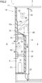
- the refrigeration apparatus for transport (10) includes a casing (11) and a refrigerant circuit (C).
- the casing (11) includes a division wall (12) and a partition plate (15).
- An internal flow path (20) is formed inside the division wall (12). Air for cooling the articles to be transported in the storage space (5) flows through the internal flow path (20).
- An external chamber (S) is formed outside the division wall (12). The division wall (12) separates the internal flow path (20) from the external chamber (S).
- the division wall (12) includes an exterior wall (12a) and an interior wall (12b).
- the exterior wall (12a) is located outside the container body (2).
- the interior wall (12b) is located inside the container body (2).
- the exterior wall (12a) and the interior wall (12b) are made of, for example, an aluminum alloy.
- the exterior wall (12a) closes the opening of the container body (2).
- the exterior wall (12a) is attached to a peripheral portion of the opening of the container body (2).
- the external chamber (S) is formed in a portion of the exterior wall (12a) bulging toward the inside of the container body (2).
- the interior wall (12b) faces the exterior wall (12a).
- the interior wall (12b) has a shape conforming to the exterior wall (12a).
- the interior wall (12b) is disposed at a distance from the exterior wall (12a).
- the lower portion of the interior wall (12b) bulges toward the inside of the container body (2).
- a heat insulator (13) is provided between the interior wall (12b) and the exterior wall (12a).
- the partition plate (15) is disposed on the inner side of the container body (2) with respect to the interior wall (12b).
- the internal flow path (20) is formed between the division wall (12) and the partition plate (15).
- An inflow port (21) is formed between an upper end of the partition plate (15) and a top panel of the container body (2).
- An outflow port (22) is formed between a lower end of the partition plate (15) and a lower end of the division wall (12).
- the internal flow path (20) extends from the inflow port (21) to the outflow port (22).
- the internal flow path (20) includes an upper flow path (23) and a lower flow path (24).
- the upper flow path (23) is an upper portion of the internal flow path (20).
- the lower flow path (24) is a lower portion of the internal flow path (20).
- the lower flow path (24) is located at a position corresponding to the bulging portion of the division wall (12).
- the refrigerant circuit (C) has refrigerant filled therein.
- the refrigerant circulates in the refrigerant circuit (C) to perform a vapor compression refrigeration cycle.
- the refrigerant circuit (C) includes a compressor (31), an external heat exchanger (32), an expansion valve (33), an internal heat exchanger (60), and a refrigerant pipe connecting these components.
- the compressor (31) is disposed in a first space (S1) corresponding to a lower portion of the external chamber (S).
- the compressor (31) sucks and compresses a low-pressure refrigerant.
- the compressor (31) discharges the compressed refrigerant as a high-pressure refrigerant.
- the external heat exchanger (32) is disposed in a second space (S2) corresponding to an upper portion of the external chamber (S).
- the external heat exchanger (32) is a fin-and-tube heat exchanger.
- the external heat exchanger (32) is a so-called four-side heat exchanger.
- the external heat exchanger (32) functions as a condenser or a radiator.
- the external heat exchanger corresponds to a heat exchanger of the present invention.
- the internal heat exchanger (60) is arranged in the internal flow path (20).
- the internal heat exchanger (60) is supported between the division wall (12) and the partition plate (15).
- the internal heat exchanger (60) is disposed above the bulging portion of the interior wall (12b).
- the internal heat exchanger (60) is a fin-and-tube heat exchanger.
- the internal heat exchanger (60) functions as an evaporator.
- the refrigeration apparatus for transport (10) includes a single external fan (34).
- the external fan (34) is arranged in the second space (S2) of the external chamber (S).
- the external fan (34) is arranged inside the four heat-exchange portions of the external heat exchanger (32).
- the external fan (34) is a propeller fan.
- the refrigeration apparatus for transport (10) includes two internal fans (35).
- the internal fans (35) are arranged in the upper flow path (23) of the internal flow path (20).
- the internal fans (35) are arranged above the internal heat exchanger (60).
- the internal fans (35) are arranged upstream of the internal heat exchanger (60) in the direction of air flow.
- the internal fans (35) are propeller fans.
- the internal fans (35) may be reduced to one, or may be increased to three or more.
- the operation causes the internal air in the storage space (5) to flow into the upper flow path (23) of the internal flow path (20) via the inflow port (21).
- Air in the upper flow path (23) of the internal flow path (20) passes through the internal heat exchanger (60) and flows through the lower flow path (24).
- the air in the lower flow path (24) flows out into the storage space (5) via the outflow port (22).
- the refrigeration apparatus for transport (10) includes a heater (H).
- the heater (H) is arranged below the internal heat exchanger (60).
- the heater (H) is attached to a lower portion of the internal heat exchanger (60).
- the internal heat exchanger (60) is heated.
- the heat of the heater (H) melts frost attached to the internal heat exchanger (60).
- the heater (H) is used to defrost the internal heat exchanger (60).
- the refrigeration apparatus for transport (10) includes an electric component box (36).
- the electric component box (36) is arranged in the second space (S2) of the external chamber (S).
- the electric component box (36) houses therein a reactor, a power supply circuit board, a control board, and the like.
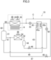
- FIG. 3 Details of the refrigerant circuit (C) will be described with reference to FIG. 3 .
- components surrounded by a broken line square are internal ones, and the other components are external ones.
- the refrigerant circuit (C) includes, as main components, the compressor (31), the external heat exchanger (32), the expansion valve (33), and the internal heat exchanger (60).
- the expansion valve (33) is an electronic expansion valve having a variable opening degree.
- the refrigerant circuit (C) has a discharge pipe (41) and a suction pipe (42). One end of the discharge pipe (41) is connected to a discharge portion of the compressor (31). The other end of the discharge pipe (41) is connected to a gas end of the external heat exchanger (32). One end of the suction pipe (42) is connected to a suction portion of the compressor (31). The other end of the suction pipe (42) is connected to a gas end of the internal heat exchanger (60).
- the refrigerant circuit (C) includes a liquid pipe (43), a receiver (44), a cooling heat exchanger (45), a first on-off valve (46), a connecting pipe (47), a second on-off valve (48), an injection pipe (49), and an injection valve (50).
- the receiver (44) is provided for the liquid pipe (43).
- the receiver (44) is a container that stores the refrigerant.
- the cooling heat exchanger (45) has a first flow path (45a) and a second flow path (45b).
- the cooling heat exchanger (45) exchanges heat between the refrigerant in the first flow path (45a) and the refrigerant in the second flow path (45b).
- the cooling heat exchanger (45) is, for example, a plate heat exchanger.
- the first flow path (45a) is a portion of the liquid pipe (43).
- the second flow path (45b) is a portion of the injection pipe (49).
- the cooling heat exchanger (45) cools the refrigerant flowing through the liquid pipe (43).
- the first on-off valve (46) is arranged in the liquid pipe (43) to be located between the receiver (44) and the first flow path (45a).
- the first on-off valve (46) is an electromagnetic valve that can be opened and closed.
- the connecting pipe (47) allows a high-pressure line and a low-pressure line of the refrigerant circuit (C) to communicate with each other.
- One end of the connecting pipe (47) is connected to the discharge pipe (41).
- the other end of the connecting pipe (47) is connected to the liquid pipe (43) to be located between the expansion valve (33) and the internal heat exchanger (60).
- the second on-off valve (48) is provided for the connecting pipe (47).
- the second on-off valve (48) is an electromagnetic valve that can be opened and closed.
- the injection pipe (49) introduces the refrigerant into an intermediate-pressure portion of the compressor (31).
- One end of the injection pipe (49) is connected to the liquid pipe (43) to be located between the receiver (44) and the first flow path (45a).
- the other end of the injection pipe (49) is connected to the intermediate-pressure portion of the compressor (31).
- the intermediate pressure which is the pressure of the intermediate-pressure portion, is a pressure in a range between the suction pressure and the discharge pressure of the compressor (31).
- the injection valve (50) is arranged upstream of the second flow path (45b) in the injection pipe (49).
- the injection valve (50) is an electronic expansion valve having a variable opening degree.
- the refrigerant compressed by the compressor (31) flows through the external heat exchanger (32).
- the refrigerant in the external heat exchanger (32) dissipates heat to the outside air to condense.
- the condensed refrigerant passes through the receiver (44).
- Part of the refrigerant that has passed through the receiver (44) flows through the first flow path (45a) of the cooling heat exchanger (45).
- the remaining of the refrigerant that has passed through the receiver (44) flows through the injection pipe (49), and is decompressed to the intermediate pressure by the injection valve (50).
- the decompressed refrigerant is introduced into the intermediate-pressure portion of the compressor (31).
- the refrigerant in the second flow path (45b) absorbs heat from the refrigerant in the first flow path (45a) to evaporate. This cools the refrigerant in the first flow path (45a). In other words, the degree of subcooling of the refrigerant flowing through the first flow path (45a) increases.
- the refrigerant cooled in the cooling heat exchanger (45) is decompressed to a low pressure by the expansion valve (33).
- the decompressed refrigerant flows through the internal heat exchanger (60).
- the refrigerant in the internal heat exchanger (60) absorbs heat from the inside air to evaporate.
- the internal heat exchanger (60) cools the inside air.
- the evaporated refrigerant is sucked into the compressor (31) and compressed again.
- the air in the container body (2) circulates through the storage space (5) and the internal flow path (20).
- the internal heat exchanger (60) cools the inside air in the internal flow path (20).
- the air in the storage space (5) can be cooled and adjusted to a predetermined temperature.
- a front panel (16) of the casing (11) and its peripheral structure will be described in detail.
- the terms “front,” “rear,” “right,” “left,” “upper,” and “lower” described below are based on a case where the front panel (16) of the casing (11) is viewed from the front.
- a front panel (16) is provided to a front surface of the casing (11), which is one of side surfaces of the casing (11).
- the front panel (16) extends in a vertical direction so as to partition the outdoor space (O) and the second space (S2) from each other.
- the second space (S2) is formed behind the front panel (16).
- the external heat exchanger (32) and the external fan (34) are disposed in the second space (S2).
- the second space (S2) corresponds to the accommodation chamber (S2).
- the front panel (16) corresponds to a partition portion.
- the front panel (16) is provided with an outlet grille (17).
- the outlet grille (17) is disposed at the center of the front panel (16).
- the outlet grille (17) is located in front of the external fan (34).
- the outlet grille (17) provides communication between the second space (S2) and the outdoor space (O). In the second space (S2), the air having passed through the external heat exchanger (32) is blown out into the outdoor space (O) through the outlet grille (17).
- the external heat exchanger (32) is disposed opposite to the outdoor space (O) with respect to the front panel (16).
- the external heat exchanger (32) is provided in the second space (S2) so as to surround the outlet grille (17).
- the external heat exchanger (32) has a substantially quadrangular shape in a front view viewed from the outdoor space (O) toward the second space (S2). More specifically, the external heat exchanger (32) has a quadrangular shape having one side with an omitted end in the front view.
- the external heat exchanger (32) includes heat transfer tubes and a large number of fins through which the heat transfer tubes pass.
- the heat transfer tubes are bent into a substantially quadrangular shape in the front view.
- the large number of fins are aligned in the extending direction of the heat transfer tubes.
- the heat transfer tubes and fins are made of a copper material.
- the external heat exchanger (32) includes four heat-exchange portions (32a, 32b, 32c, 32d) each including a heat transfer tube and fins.
- the external heat exchanger (32) includes a first heat-exchange portion (32a), a second heat-exchange portion (32b), a third heat-exchange portion (32c), and a fourth heat-exchange portion (32d).
- the first heat-exchange portion (32a) corresponds to a lower surface of the external heat exchanger (32).
- the second heat-exchange portion (32b) corresponds to a left surface of the external heat exchanger (32).
- the third heat-exchange portion (32c) corresponds to an upper surface of the external heat exchanger (32).
- the fourth heat-exchange portion (32d) corresponds to a right surface of the external heat exchanger (32).
- the first heat-exchange portion (32a), the second heat-exchange portion (32b), the third heat-exchange portion (32c), and the fourth heat-exchange portion (32d) are sequentially connected.
- a gap corresponding to the above-described omitted portion is formed.
- a coating film made of a cationic paint (hereinafter referred to as a cationic coating film) is provided on the surface of the external heat exchanger (32). More specifically, an assembly of the external heat exchanger (32) is immersed in a raw material containing a cationic paint. A direct current is applied to the assembly in this state, thereby forming a cationic coating film on the surface of the external heat exchanger (32). More specifically, a cationic coating film is formed on the surfaces of the fins, heat transfer tubes, tube plates, or the like.
- the cationic paint is excellent in corrosion resistance and rust prevention.
- the transport container (1) is transported by sea on a ship or the like.
- the cationic coating film retards rusting or corrosion of the external heat exchanger (32) due to the influence of salt water.
- a pair of fork pockets (70) are provided on the front surface of the casing (11).
- the pair of fork pockets (70) includes a first fork pocket (70A) and a second fork pocket (70B).
- the first fork pocket (70A) is provided in the front panel (16) which serves as the partition portion.
- the first fork pocket (70A) is disposed above the outlet grille (17).
- the second fork pocket (70B) is disposed above the electric component box (36).
- the first fork pocket (70A) and the second fork pocket (70B) are located at the same height.
- each of the fork pockets (70) is formed in a horizontally long quadrangular shape in the front view.
- the fork pocket (70) is formed in a horizontally long rectangular tubular shape.
- the fork pocket (70) includes a main body (71) and a pair of long plates (72).
- the main body (71) is formed in a horizontally long rectangular tubular shape having an open part at its lower part.
- the pair of long plates (72) are attached to the open part of the main body (71).
- the main body (71) includes an upper plate (71a), a first side plate (71b), a second side plate (71c), a first bottom plate (71d), and a second bottom plate (71e).
- the first side plate (71b) extends downward from a left end of the upper plate (71a).
- the second side plate (71c) extends downward from a right end of the upper plate (71a).
- the first bottom plate (71d) extends rightward from a lower end of the first side plate (71b).
- the second bottom plate (71e) extends leftward from a lower end of the second side plate (71c).
- the first bottom plate (71d) and the second bottom plate (71e) are separated from each other in the horizontal direction.
- the pair of long plates (72) are arranged at front and rear portions of the fork pocket (70). One of the pair of long plates (72) is located at the front edge of the main body (71), and the other is located at the rear edge of the main body (71). The pair of long plates (72) extend in the horizontal direction across the first side plate (71b) and the second side plate (71c).
- an insertion opening (73) is provided on the front side of each fork pocket (70).
- a pair of claws of a forklift can be inserted into these insertion openings (73).
- a pair of claws of a forklift are inserted into respective insertion openings (73).
- Each fork pocket (70) has a communication hole (74).
- the communication hole (74) is defined by the first bottom plate (71d), the second bottom plate (71e), and the two long plates (72).
- the communication hole (74) opens downward.
- An air passage (75) is formed in the fork pocket (70) from the insertion opening (73) to the communication hole (74).
- the external fan (34) When the external fan (34) operates, the operation causes outdoor air to flow into each of the fork pockets (70) through the insertion opening (73) and flow through the air passage (75). Air in the air passage (75) flows into the external heat exchanger (32) through the communication hole (74).
- the flow of the outdoor air is indicated by an arrow of a one dot chain line.
- a plurality of suction ports (80) are provided in the front panel (16).
- the plurality of suction ports (80) correspond to openings for providing communication between the outdoor space (O) and the second space (S2).
- the plurality of suction ports (80) include a plurality of first suction ports (80A) and a plurality of second suction ports (80B). Structures of the first suction port (80A) and the second suction port (80B) are basically the same.
- a plurality of first suction ports (80A) are located above the external heat exchanger (32).
- a plurality of second suction ports (80B) are located on the left side of the external heat exchanger (32).
- the plurality of first suction ports (80A) are located above the third heat-exchange portion (32c).
- the plurality of second suction ports (80B) are located on the left side of the second heat-exchange portion (32b).
- first suction ports (80A) On the front panel (16), two rows of five first suction ports (80A) arranged side by side are aligned in the vertical direction.
- the five first suction ports (80A) in each row include three on the left side and two on the right side of the first fork pocket (70A).
- hole groups each includes 15 second suction ports (80B) arranged in the vertical direction are arranged in the vertical direction at predetermined intervals.
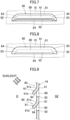
- the suction port (80) extends in the horizontal direction.
- the suction port (80) has a substantially trapezoidal shape.
- the suction port (80) has an upper edge portion (81), a lower edge portion (82), a first side edge portion (83), and a second side edge portion (84).
- the upper edge portion (81) corresponds to an upper side of the suction port (80).
- the lower edge portion (82) corresponds to a lower side of the suction port (80).
- the left-right length of the upper edge portion (81) is shorter than the left-right length of the lower edge portion (82).
- the first side edge portion (83) is formed at a left end portion of the suction port (80).
- the second side edge portion (84) is formed at a right end portion of the suction port (80).
- the first side edge portion (83) is formed in a substantially arc shape bulging obliquely leftward.
- the second side edge portion (84) is formed in a substantially arc shape bulging obliquely rightward.
- the front panel (16) is provided with a plurality of light shielding portions (90).
- the light shielding portions (90) are provided for the respective suction ports (80).
- one light shielding portion (90) is provided for each of the plurality of first suction ports (80A) and each of the plurality of second suction ports (80B).
- the light shielding portion (90) is formed by a press working process on the front panel (16).
- the light shielding portion (90) has an eaves portion (91) and two sidewall portions (92, 93).
- the eaves portion (91) is disposed above an associated one of the suction ports (80).
- the eaves portion (91) is provided at an upper edge portion (81) of the suction port (80).
- the eaves portion (91) is provided along the upper edge portion (81) of the suction port (80) in the horizontal direction.
- the eaves portion (91) is provided from one end to the other end of the upper edge portion (81) in the horizontal direction.
- a base portion (91a) of the eaves portion (91) is integrated with the upper edge portion (81) of the suction port (80).
- the eaves portion (91) extends downward from the upper edge portion (81) of the suction port (80).
- the eaves portion (91) of the present embodiment extends downward as a whole. More specifically, the eaves portion (91) extends forward and obliquely downward from the upper edge portion (81) of the suction port (80). There is a gap between the eaves portion (91) and the suction port (80).
- An inflow port (94) is formed between the lower end (91b) of the eaves portion (91) and the lower edge portion (82) of the suction port (80). The inflow port (94) is open downward. Strictly speaking, the inflow port (94) is open forward and obliquely downward.
- the two sidewall portions include a first sidewall portion (92) and a second sidewall portion (93).
- the first sidewall portion (92) is provided at the left end of the light shielding portion (90).
- the second sidewall portion (93) is provided at the right end of the light shielding portion (90).
- the first sidewall portion (92) extends from the first side edge portion (83) of the suction port (80) to the left end portion of the eaves portion (91).
- the first sidewall portion (92) protrudes forward and obliquely rightward from the first side edge portion (83).
- the second sidewall portion (93) extends from the second side edge portion (84) of the suction port (80) to the right end portion of the eaves portion (91).
- the second sidewall portion (93) protrudes forward and obliquely leftward from the second side edge portion (84).
- the light shielding portion (90) covers at least an upper half of the suction port (80) in a front view.
- the light shielding portion (90) of the present embodiment covers most of the area of the suction port (80) in the front view.
- the lower end of the eaves portion (91) is located higher than the lower edge portion (82) of the suction port (80).
- the inflow port (21) and the suction port (80) overlap each other in the plate thickness direction of the front panel (16).
- the outdoor air in front of the suction port (80) can be sucked into the second space (S2) through the inflow port (94) and the suction port (80).
- the eaves portion (91) of the suction port (80) can reduce the entry of sunlight into the second space (S2) through the suction port (80). This facilitates reducing the sunlight reaching the external heat exchanger (32) in the second space (S2), thereby reducing the deterioration of the external heat exchanger (32) caused by sunlight.
- the transport container (1) may also be transported to countries where the ultraviolet rays of sunlight are relatively strong. Thus, the exposure of the external heat exchanger (32) to the sunlight would easily cause the deterioration of the external heat exchanger (32).
- the eaves portion (91) can reduce such deterioration.
- the eaves portion (91) is provided on the upper edge of the suction port (80). Thus, the eaves portion (91) can prevent the sunlight from entering from above the suction port (80).
- the sidewall portions (92, 93) are provided on lateral sides of the suction port (80).
- the eaves portion (91) can prevent the sunlight from entering from lateral sides of the suction port (80).
- the eaves portion (91) and the sidewall portions (92, 93) are integrated.
- the eaves portion (91) and the sidewall portions (83, 84) can be formed by a press working process or the like.
- the light shielding portion (90) can be improved in strength with the configuration in which the eaves portion (91) and sidewall portions (92, 93) are integrated.
- the suction port (80) is a long hole elongated in the horizontal direction. This configuration can reduce the entry of the sunlight into the suction port (80) while making the forward protrusion of the eaves portion (91) relatively short.
- the plurality of first suction ports (80A) are located above the external heat exchanger (32) in the front view. By providing the eaves portion (91) to the first suction port (80A), it becomes possible to reduce the entry of the sunlight coming from above the first suction port (80A) onto the external heat exchanger (32) via the first suction port (80A).
- the cationic coating film On the surface of the external heat exchanger (32), the cationic coating film is provided.
- the cationic coating film retards rusting or corrosion of the external heat exchanger (32).
- the cationic coating film is susceptible to degradation due to sunlight.
- the exposure of the external heat exchanger (32) to the sunlight would deteriorate the cationic coating film.
- the eaves portion (91) reduces the entry of the sunlight into the second space (S2), thereby reducing the deterioration of the cationic coating film.
- this makes it possible for the cationic coating film to provide long-term retardation of the rusting or corrosion of the external heat exchanger (32).
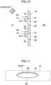
- a light shielding portion (90) of a first variation differs from the light shielding portion (90) of the above embodiment in the structure of the eaves portion (91).
- an eaves portion (91) herein has an upper wall portion (91c) and a front wall portion (91d).
- the upper wall portion (91c) protrudes from an upper edge portion (81) of a suction port (80) horizontally forward.
- the front wall portion (91d) extends vertically downward from a front edge of the upper wall portion (91c).
- the first variation is configured such that only a portion of the eaves portion (91) extends downward.
- the front wall portion (91d) is located in front of the suction port (80) and covers at least an upper portion of the suction port (80).
- An inflow port (94) is formed between a lower edge of the front wall portion (91d) and a lower edge portion (82) of the suction port (80).
- the first variation with the eaves portion (91) above the suction port (80) can also reduce the entry of the sunlight into the second space (S2) via the suction port (80).
- a suction port (80) of a second variation has an oval shape elongated in the horizontal direction. This configuration is such that an upper-half edge portion of the suction port (80) constitutes an upper edge portion (81). A lower-half edge portion of the suction port (80) constitutes a lower edge portion (82).
- the eaves portion (91) of a light shielding portion (90) is provided at the upper edge portion (81) of the suction port (80).
- the eaves portion (91) has a semi-oval shape along the entire upper edge portion (81).
- the eaves portion (91) is configured to block the sunlight from entering the suction port (80) from above.
- the suction port (80) may have a perfect circular shape. Again in this configuration, the upper-half edge of the suction port (80) constitutes the upper edge portion (81). In this configuration, too, in which the lower-half edge of the suction port (80) constitutes the lower edge portion (82), the eaves portion (91) of the light shielding portion (90) is provided at the upper edge portion (81).
- the "upper edge portion" of an opening as described in this disclosure means the edge formed on the upper half of the opening when the shape of the opening has a circular shape, such as an oblong, oval, or perfect circular shape.
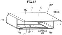
- Athird variation illustrated in FIG. 12 is configured such that an eaves portion (91) is provided above an insertion opening (73) of a fork pocket (70).
- the insertion opening (73) corresponds to an opening for providing communication between the outdoor space (O) and the second space (S2).
- An eaves portion (91) protrudes forward from the upper plate (71a) of the foregoing embodiment, with which the eaves portion (91) is integrated.
- the upper plate (71a) has a substantially rectangular plate-like shape elongated in the horizontal direction.
- the upper plate (71a) corresponds to the upper edge portion of the insertion opening (73).
- the eaves portion (91) can reduce the entry of the sunlight into the second space (S2) via the insertion opening (73).
- the eaves portion (91) extends along an axial direction of the tubular shape of the fork pocket (70). This configuration can reduce the possibility that the claw of the forklift may interfere with the eaves portion (91).
- the transport container (1) may be used for land transportation.
- the transport container (1) is conveyed by a land transporter, such as a vehicle. More specifically, the transport container (1) may be mounted on a trailer.
- the external heat exchanger (32) may, in aspects not according to claim 1, be a three-side heat exchanger.
- the external heat exchanger (32) is configured in a substantially U-shape in the front view.
- the suction port (80) is located above the heat exchanger (32) in the front view.
- the eaves portion (91) may be provided at a position higher than the upper edge portion of the opening (73, 80).
- the light shielding portion (90) may include the eaves portion (91) only, without the sidewall portions (92, 93).
- the sidewall portions (92, 93) may be portions separate from the eaves portion (91).
- the external heat exchanger (32) may, in aspects not according to claim 1, be a three-side heat exchanger configured in a U-shape.
- the external heat exchanger (32) may include no cationic coating film on its surface.
- the present disclosure is useful for refrigeration apparatuses for transport and transport containers.
Landscapes
- Engineering & Computer Science (AREA)
- Mechanical Engineering (AREA)
- General Engineering & Computer Science (AREA)
- Physics & Mathematics (AREA)
- Thermal Sciences (AREA)
- Chemical & Material Sciences (AREA)
- Combustion & Propulsion (AREA)
- Devices That Are Associated With Refrigeration Equipment (AREA)
- Air Filters, Heat-Exchange Apparatuses, And Housings Of Air-Conditioning Units (AREA)
- Cold Air Circulating Systems And Constructional Details In Refrigerators (AREA)
Claims (10)
- Kühlvorrichtung für den Transport, umfassend:einen Wärmetauscher (32);ein Gehäuse (11), das eine Aufnahmekammer (S2) bildet, um den Wärmetauscher (32) darin aufzunehmen,wobei das Gehäuse (11) mit einem Trennabschnitt (16) bereitgestellt ist, der sich in einer vertikalen Richtung erstreckt, um einen Außenraum (O) und die Aufnahmekammer (S2) voneinander zu trennen,wobei der Trennabschnitt (16) eine Öffnung (73, 80) aufweist, um eine Verbindung zwischen dem Außenraum (O) und der Aufnahmekammer (S2) bereitzustellen; undeinen Traufabschnitt (91) oberhalb der Öffnung (73, 80), wobei die Öffnung (73, 80) in der Vorderansicht oberhalb des Wärmetauschers (32) angeordnet ist;dadurch gekennzeichnet, dassder Wärmetauscher (32) ein vierseitiger Wärmetauscher ist, der eine im Wesentlichen viereckige Form aufweist und erste bis vierte Wärmetauscherabschnitte (32a-32d) umfasst, die jeweils ein Wärmeübertragungsrohr und Rippen einschließen und in einer Vorderansicht vom Außenraum (O) zur Aufnahmekammer (S2) hin gesehen in einem Viereck angeordnet sind.
- Kühlvorrichtung für den Transport nach Anspruch 1, wobei der Traufabschnitt (91) an einem oberen Rand der Öffnung (73, 80) bereitgestellt ist.
- Kühlvorrichtung für den Transport nach Anspruch 1 oder 2, weiter umfassend: Seitenwandabschnitte (92, 93) an den seitlichen Seiten der Öffnung (73, 80).
- Kühlvorrichtung für den Transport nach Anspruch 3, wobei der Traufabschnitt (91) eine mit den Seitenwandabschnitten (92, 93) durchgehende Form aufweist.
- Kühlvorrichtung für den Transport nach einem der Ansprüche 1 bis 4, wobei die Öffnung (73, 80) ein Langloch ist, das sich in horizontaler Richtung erstreckt.
- Kühlvorrichtung für den Transport nach einem der Ansprüche 1 bis 5, wobei der Traufabschnitt (91) einen sich nach unten erstreckenden Abschnitt einschließt.
- Kühlvorrichtung für den Transport nach einem der Ansprüche 1 bis 6, weiter umfassend:ein Gebläse (34), das in der Aufnahmekammer (S2) bereitgestellt ist, wobeidie Öffnung eine Ansaugöffnung (80) einschließt, durch die von dem Gebläse (34) übertragene Luft angesaugt wird.
- Kühlvorrichtung für den Transport nach einem der Ansprüche 1 bis 7, wobei der Trennabschnitt (16) eine Gabeltasche (70) aufweist, und die Öffnung eine Einführöffnung (73) der Gabeltasche (70) einschließt.
- Kühlvorrichtung für den Transport nach einem der Ansprüche 1 bis 8, weiter umfassend:
einen Beschichtungsfilm auf einer Oberfläche des Wärmetauschers (32), wobei der Beschichtungsfilm aus einer kationischen Farbe hergestellt ist. - Transportbehälter, umfassend:die Kühlvorrichtung für den Transport (10) nach einem der Ansprüche 1 bis 9; undeinen Behälterkörper (2).
Applications Claiming Priority (2)
| Application Number | Priority Date | Filing Date | Title |
|---|---|---|---|
| JP2020038721A JP7025667B2 (ja) | 2020-03-06 | 2020-03-06 | 輸送用冷凍装置、及び輸送用コンテナ |
| PCT/JP2021/006894 WO2021177110A1 (ja) | 2020-03-06 | 2021-02-24 | 輸送用冷凍装置、及び輸送用コンテナ |
Publications (3)
| Publication Number | Publication Date |
|---|---|
| EP4102155A1 EP4102155A1 (de) | 2022-12-14 |
| EP4102155A4 EP4102155A4 (de) | 2023-08-09 |
| EP4102155B1 true EP4102155B1 (de) | 2025-01-01 |
Family
ID=77613033
Family Applications (1)
| Application Number | Title | Priority Date | Filing Date |
|---|---|---|---|
| EP21765157.9A Active EP4102155B1 (de) | 2020-03-06 | 2021-02-24 | Kühlvorrichtung für den versand und transportbehälter |
Country Status (6)
| Country | Link |
|---|---|
| US (1) | US12018880B2 (de) |
| EP (1) | EP4102155B1 (de) |
| JP (1) | JP7025667B2 (de) |
| CN (1) | CN115210516A (de) |
| DK (1) | DK4102155T3 (de) |
| WO (1) | WO2021177110A1 (de) |
Citations (3)
| Publication number | Priority date | Publication date | Assignee | Title |
|---|---|---|---|---|
| US2949751A (en) * | 1957-09-06 | 1960-08-23 | Pacific Car & Foundry Co | Mechanical refrigerator cars |
| US4424684A (en) * | 1982-01-05 | 1984-01-10 | Thermo King Corporation | Condenser section for container refrigeration unit |
| US6318098B1 (en) * | 1997-12-05 | 2001-11-20 | Dometic Corporation | Ambient temperature control for absorption refrigerator |
Family Cites Families (21)
| Publication number | Priority date | Publication date | Assignee | Title |
|---|---|---|---|---|
| US2791098A (en) * | 1954-05-24 | 1957-05-07 | Dole Refrigerating Co | Car refrigeration assembly with internal combustion motor |
| US2746268A (en) * | 1955-01-14 | 1956-05-22 | Knudsen Creamery Co Of Califor | Self-refrigerated highway truck |
| US3871188A (en) * | 1973-09-07 | 1975-03-18 | Thermo King Corp | Demountable transportation refrigeration unit |
| JPS55164264A (en) * | 1979-06-08 | 1980-12-20 | Hitachi Ltd | Aqueous coating composition and heat exchanger coated with it |
| US4551986A (en) | 1984-10-17 | 1985-11-12 | Westinghouse Electric Corp. | Transport refrigeration unit |
| JPH0686976B2 (ja) | 1985-10-17 | 1994-11-02 | ダイキン工業株式会社 | コンテナ用冷凍装置 |
| JP2524187B2 (ja) * | 1988-04-08 | 1996-08-14 | ヤンマーディーゼル株式会社 | 冷蔵冷凍輸送コンテナ |
| US4802342A (en) * | 1988-04-18 | 1989-02-07 | Thermo King Corporation | Protective grille and air flow straightener for transport refrigeration apparatus |
| JPH10160334A (ja) * | 1996-11-29 | 1998-06-19 | Daikin Ind Ltd | コンテナ用冷凍装置 |
| US20020174671A1 (en) * | 2001-05-22 | 2002-11-28 | Ken Wilkinson | Solar radiation screen for air conditioner condenser |
| CN1447074A (zh) * | 2002-03-21 | 2003-10-08 | 王松 | 空调室外机 |
| JP3782790B2 (ja) * | 2003-04-28 | 2006-06-07 | ダイキン工業株式会社 | コンテナ用冷凍ユニット |
| US20080178624A1 (en) * | 2007-01-30 | 2008-07-31 | Zedney David B | Shield for air conditioner |
| US20130233524A1 (en) * | 2010-11-24 | 2013-09-12 | Carrier Corporation | Refrigeration Unit With Corrosion Durable Heat Exchanger |
| CN103502739B (zh) * | 2011-05-20 | 2016-06-01 | 大金工业株式会社 | 制冷装置的室外机组 |
| US20140157794A1 (en) * | 2012-12-12 | 2014-06-12 | Ryan McGann | Solar Powered Refrigerated Container |
| WO2016109145A2 (en) * | 2014-12-30 | 2016-07-07 | Carrier Corporation | Access panel |
| FI20155283A7 (fi) * | 2015-04-16 | 2016-10-17 | Ce Rental Oy | Höyrystin lämpöpumppulaitteistoa varten |
| CN105546862A (zh) * | 2016-01-22 | 2016-05-04 | 珠海格力电器股份有限公司 | 制冷机组及集装箱、冷冻运输车辆 |
| US11435093B2 (en) * | 2017-12-26 | 2022-09-06 | Gree Electric Appliances (Wuhan) Co., Ltd. | Air-conditioning outdoor device and air conditioner unit |
| CN209819811U (zh) * | 2019-03-27 | 2019-12-20 | 同济大学 | 直流式空调含有害介质排风中低品位热量的增效系统装置 |
-
2020
- 2020-03-06 JP JP2020038721A patent/JP7025667B2/ja active Active
-
2021
- 2021-02-24 DK DK21765157.9T patent/DK4102155T3/da active
- 2021-02-24 WO PCT/JP2021/006894 patent/WO2021177110A1/ja not_active Ceased
- 2021-02-24 EP EP21765157.9A patent/EP4102155B1/de active Active
- 2021-02-24 CN CN202180018974.0A patent/CN115210516A/zh active Pending
-
2022
- 2022-08-18 US US17/890,832 patent/US12018880B2/en active Active
Patent Citations (3)
| Publication number | Priority date | Publication date | Assignee | Title |
|---|---|---|---|---|
| US2949751A (en) * | 1957-09-06 | 1960-08-23 | Pacific Car & Foundry Co | Mechanical refrigerator cars |
| US4424684A (en) * | 1982-01-05 | 1984-01-10 | Thermo King Corporation | Condenser section for container refrigeration unit |
| US6318098B1 (en) * | 1997-12-05 | 2001-11-20 | Dometic Corporation | Ambient temperature control for absorption refrigerator |
Also Published As
| Publication number | Publication date |
|---|---|
| DK4102155T3 (da) | 2025-02-10 |
| US12018880B2 (en) | 2024-06-25 |
| WO2021177110A1 (ja) | 2021-09-10 |
| US20220404087A1 (en) | 2022-12-22 |
| JP2021139576A (ja) | 2021-09-16 |
| CN115210516A (zh) | 2022-10-18 |
| EP4102155A1 (de) | 2022-12-14 |
| JP7025667B2 (ja) | 2022-02-25 |
| EP4102155A4 (de) | 2023-08-09 |
Similar Documents
| Publication | Publication Date | Title |
|---|---|---|
| EP3557162A1 (de) | Kühlschrank | |
| EP3502592A1 (de) | Kühlvorrichtung | |
| EP4102155B1 (de) | Kühlvorrichtung für den versand und transportbehälter | |
| US20210270516A1 (en) | Refrigerated sales cabinet | |
| TWI568639B (zh) | Equipment for the installation of refrigerators for foodstuffs on ships and for the installation of refrigerators on ships | |
| US12264876B2 (en) | Refrigeration apparatus for shipping, and shipping container | |
| US20220357094A1 (en) | Refrigeration apparatus for transport and transport container | |
| JP6974770B2 (ja) | 輸送用冷凍装置、及び輸送用コンテナ | |
| JP7001939B2 (ja) | 輸送用冷凍装置、及び輸送用コンテナ | |
| JPH0634256A (ja) | 熱交換装置及びこれを備えたコンテナ用冷凍ユニット | |
| JP2011112267A (ja) | コンテナ用冷凍装置 | |
| KR102006491B1 (ko) | 함정용 강화랙 | |
| JP6989799B2 (ja) | 輸送用冷凍装置及び輸送用コンテナ | |
| JP7212275B2 (ja) | 熱交換器および熱交換器の製造方法 | |
| JP6989798B2 (ja) | 輸送用冷凍装置及び輸送用コンテナ | |
| CN114341576A (zh) | 集装箱用制冷装置 | |
| JP2984472B2 (ja) | エバポレータ及びこれを備えたコンテナ用冷凍ユニット | |
| JP2021139802A (ja) | 輸送用冷凍装置及び輸送用コンテナ | |
| JP2021139572A (ja) | 熱交換器および熱交換器の製造方法 | |
| JP2021139575A (ja) | 輸送用冷凍装置、及び輸送用コンテナ | |
| JPH0618149A (ja) | コンテナ用冷凍ユニットの換気装置 | |
| JP2013002727A (ja) | 熱交換器のドレン構造 | |
| KR20080104711A (ko) | 증발기 | |
| JP2010117049A (ja) | 冷凍車 |
Legal Events
| Date | Code | Title | Description |
|---|---|---|---|
| STAA | Information on the status of an ep patent application or granted ep patent |
Free format text: STATUS: THE INTERNATIONAL PUBLICATION HAS BEEN MADE |
|
| PUAI | Public reference made under article 153(3) epc to a published international application that has entered the european phase |
Free format text: ORIGINAL CODE: 0009012 |
|
| STAA | Information on the status of an ep patent application or granted ep patent |
Free format text: STATUS: REQUEST FOR EXAMINATION WAS MADE |
|
| 17P | Request for examination filed |
Effective date: 20220908 |
|
| AK | Designated contracting states |
Kind code of ref document: A1 Designated state(s): AL AT BE BG CH CY CZ DE DK EE ES FI FR GB GR HR HU IE IS IT LI LT LU LV MC MK MT NL NO PL PT RO RS SE SI SK SM TR |
|
| RAP3 | Party data changed (applicant data changed or rights of an application transferred) |
Owner name: DAIKIN INDUSTRIES, LTD. |
|
| DAV | Request for validation of the european patent (deleted) | ||
| DAX | Request for extension of the european patent (deleted) | ||
| P01 | Opt-out of the competence of the unified patent court (upc) registered |
Effective date: 20230525 |
|
| A4 | Supplementary search report drawn up and despatched |
Effective date: 20230712 |
|
| RIC1 | Information provided on ipc code assigned before grant |
Ipc: F24F 13/20 20060101ALI20230706BHEP Ipc: F25D 19/00 20060101ALI20230706BHEP Ipc: F25D 11/00 20060101ALI20230706BHEP Ipc: F25B 39/04 20060101AFI20230706BHEP |
|
| STAA | Information on the status of an ep patent application or granted ep patent |
Free format text: STATUS: EXAMINATION IS IN PROGRESS |
|
| 17Q | First examination report despatched |
Effective date: 20240226 |
|
| GRAP | Despatch of communication of intention to grant a patent |
Free format text: ORIGINAL CODE: EPIDOSNIGR1 |
|
| STAA | Information on the status of an ep patent application or granted ep patent |
Free format text: STATUS: GRANT OF PATENT IS INTENDED |
|
| INTG | Intention to grant announced |
Effective date: 20240918 |
|
| GRAS | Grant fee paid |
Free format text: ORIGINAL CODE: EPIDOSNIGR3 |
|
| GRAA | (expected) grant |
Free format text: ORIGINAL CODE: 0009210 |
|
| STAA | Information on the status of an ep patent application or granted ep patent |
Free format text: STATUS: THE PATENT HAS BEEN GRANTED |
|
| AK | Designated contracting states |
Kind code of ref document: B1 Designated state(s): AL AT BE BG CH CY CZ DE DK EE ES FI FR GB GR HR HU IE IS IT LI LT LU LV MC MK MT NL NO PL PT RO RS SE SI SK SM TR |
|
| REG | Reference to a national code |
Ref country code: GB Ref legal event code: FG4D |
|
| REG | Reference to a national code |
Ref country code: DE Ref legal event code: R096 Ref document number: 602021024305 Country of ref document: DE |
|
| REG | Reference to a national code |
Ref country code: CH Ref legal event code: EP |
|
| REG | Reference to a national code |
Ref country code: IE Ref legal event code: FG4D Ref country code: NL Ref legal event code: FP |
|
| REG | Reference to a national code |
Ref country code: DK Ref legal event code: T3 Effective date: 20250206 |
|
| PGFP | Annual fee paid to national office [announced via postgrant information from national office to epo] |
Ref country code: DE Payment date: 20250218 Year of fee payment: 5 |
|
| PGFP | Annual fee paid to national office [announced via postgrant information from national office to epo] |
Ref country code: DK Payment date: 20250224 Year of fee payment: 5 |
|
| PGFP | Annual fee paid to national office [announced via postgrant information from national office to epo] |
Ref country code: AT Payment date: 20250417 Year of fee payment: 5 |
|
| REG | Reference to a national code |
Ref country code: LT Ref legal event code: MG9D |
|
| REG | Reference to a national code |
Ref country code: AT Ref legal event code: MK05 Ref document number: 1756615 Country of ref document: AT Kind code of ref document: T Effective date: 20250101 |
|
| PG25 | Lapsed in a contracting state [announced via postgrant information from national office to epo] |
Ref country code: FI Free format text: LAPSE BECAUSE OF FAILURE TO SUBMIT A TRANSLATION OF THE DESCRIPTION OR TO PAY THE FEE WITHIN THE PRESCRIBED TIME-LIMIT Effective date: 20250101 |
|
| PG25 | Lapsed in a contracting state [announced via postgrant information from national office to epo] |
Ref country code: PL Free format text: LAPSE BECAUSE OF FAILURE TO SUBMIT A TRANSLATION OF THE DESCRIPTION OR TO PAY THE FEE WITHIN THE PRESCRIBED TIME-LIMIT Effective date: 20250101 |
|
| PG25 | Lapsed in a contracting state [announced via postgrant information from national office to epo] |
Ref country code: ES Free format text: LAPSE BECAUSE OF FAILURE TO SUBMIT A TRANSLATION OF THE DESCRIPTION OR TO PAY THE FEE WITHIN THE PRESCRIBED TIME-LIMIT Effective date: 20250101 |
|
| PG25 | Lapsed in a contracting state [announced via postgrant information from national office to epo] |
Ref country code: IS Free format text: LAPSE BECAUSE OF FAILURE TO SUBMIT A TRANSLATION OF THE DESCRIPTION OR TO PAY THE FEE WITHIN THE PRESCRIBED TIME-LIMIT Effective date: 20250501 Ref country code: NO Free format text: LAPSE BECAUSE OF FAILURE TO SUBMIT A TRANSLATION OF THE DESCRIPTION OR TO PAY THE FEE WITHIN THE PRESCRIBED TIME-LIMIT Effective date: 20250401 |
|
| PGFP | Annual fee paid to national office [announced via postgrant information from national office to epo] |
Ref country code: IT Payment date: 20250429 Year of fee payment: 5 |
|
| PG25 | Lapsed in a contracting state [announced via postgrant information from national office to epo] |
Ref country code: HR Free format text: LAPSE BECAUSE OF FAILURE TO SUBMIT A TRANSLATION OF THE DESCRIPTION OR TO PAY THE FEE WITHIN THE PRESCRIBED TIME-LIMIT Effective date: 20250101 |
|
| PG25 | Lapsed in a contracting state [announced via postgrant information from national office to epo] |
Ref country code: LV Free format text: LAPSE BECAUSE OF FAILURE TO SUBMIT A TRANSLATION OF THE DESCRIPTION OR TO PAY THE FEE WITHIN THE PRESCRIBED TIME-LIMIT Effective date: 20250101 Ref country code: PT Free format text: LAPSE BECAUSE OF FAILURE TO SUBMIT A TRANSLATION OF THE DESCRIPTION OR TO PAY THE FEE WITHIN THE PRESCRIBED TIME-LIMIT Effective date: 20250502 |
|
| PG25 | Lapsed in a contracting state [announced via postgrant information from national office to epo] |
Ref country code: GR Free format text: LAPSE BECAUSE OF FAILURE TO SUBMIT A TRANSLATION OF THE DESCRIPTION OR TO PAY THE FEE WITHIN THE PRESCRIBED TIME-LIMIT Effective date: 20250402 Ref country code: BG Free format text: LAPSE BECAUSE OF FAILURE TO SUBMIT A TRANSLATION OF THE DESCRIPTION OR TO PAY THE FEE WITHIN THE PRESCRIBED TIME-LIMIT Effective date: 20250101 |
|
| PG25 | Lapsed in a contracting state [announced via postgrant information from national office to epo] |
Ref country code: AT Free format text: LAPSE BECAUSE OF FAILURE TO SUBMIT A TRANSLATION OF THE DESCRIPTION OR TO PAY THE FEE WITHIN THE PRESCRIBED TIME-LIMIT Effective date: 20250101 |
|
| PG25 | Lapsed in a contracting state [announced via postgrant information from national office to epo] |
Ref country code: CZ Free format text: LAPSE BECAUSE OF FAILURE TO SUBMIT A TRANSLATION OF THE DESCRIPTION OR TO PAY THE FEE WITHIN THE PRESCRIBED TIME-LIMIT Effective date: 20250101 |
|
| PG25 | Lapsed in a contracting state [announced via postgrant information from national office to epo] |
Ref country code: SE Free format text: LAPSE BECAUSE OF FAILURE TO SUBMIT A TRANSLATION OF THE DESCRIPTION OR TO PAY THE FEE WITHIN THE PRESCRIBED TIME-LIMIT Effective date: 20250101 |
|
| REG | Reference to a national code |
Ref country code: CH Ref legal event code: PL |
|
| REG | Reference to a national code |
Ref country code: DE Ref legal event code: R097 Ref document number: 602021024305 Country of ref document: DE |
|
| PG25 | Lapsed in a contracting state [announced via postgrant information from national office to epo] |
Ref country code: SM Free format text: LAPSE BECAUSE OF FAILURE TO SUBMIT A TRANSLATION OF THE DESCRIPTION OR TO PAY THE FEE WITHIN THE PRESCRIBED TIME-LIMIT Effective date: 20250101 |
|
| PG25 | Lapsed in a contracting state [announced via postgrant information from national office to epo] |
Ref country code: MC Free format text: LAPSE BECAUSE OF FAILURE TO SUBMIT A TRANSLATION OF THE DESCRIPTION OR TO PAY THE FEE WITHIN THE PRESCRIBED TIME-LIMIT Effective date: 20250101 |
|
| PG25 | Lapsed in a contracting state [announced via postgrant information from national office to epo] |
Ref country code: LU Free format text: LAPSE BECAUSE OF NON-PAYMENT OF DUE FEES Effective date: 20250224 |
|
| PG25 | Lapsed in a contracting state [announced via postgrant information from national office to epo] |
Ref country code: CH Free format text: LAPSE BECAUSE OF NON-PAYMENT OF DUE FEES Effective date: 20250228 |
|
| PG25 | Lapsed in a contracting state [announced via postgrant information from national office to epo] |
Ref country code: EE Free format text: LAPSE BECAUSE OF FAILURE TO SUBMIT A TRANSLATION OF THE DESCRIPTION OR TO PAY THE FEE WITHIN THE PRESCRIBED TIME-LIMIT Effective date: 20250101 |
|
| PG25 | Lapsed in a contracting state [announced via postgrant information from national office to epo] |
Ref country code: RO Free format text: LAPSE BECAUSE OF FAILURE TO SUBMIT A TRANSLATION OF THE DESCRIPTION OR TO PAY THE FEE WITHIN THE PRESCRIBED TIME-LIMIT Effective date: 20250101 |
|
| PG25 | Lapsed in a contracting state [announced via postgrant information from national office to epo] |
Ref country code: SK Free format text: LAPSE BECAUSE OF FAILURE TO SUBMIT A TRANSLATION OF THE DESCRIPTION OR TO PAY THE FEE WITHIN THE PRESCRIBED TIME-LIMIT Effective date: 20250101 |
|
| PLBE | No opposition filed within time limit |
Free format text: ORIGINAL CODE: 0009261 |
|
| STAA | Information on the status of an ep patent application or granted ep patent |
Free format text: STATUS: NO OPPOSITION FILED WITHIN TIME LIMIT |
|
| REG | Reference to a national code |
Ref country code: BE Ref legal event code: MM Effective date: 20250228 |
|
| 26N | No opposition filed |
Effective date: 20251002 |
|
| GBPC | Gb: european patent ceased through non-payment of renewal fee |
Effective date: 20250401 |
|
| PG25 | Lapsed in a contracting state [announced via postgrant information from national office to epo] |
Ref country code: GB Free format text: LAPSE BECAUSE OF NON-PAYMENT OF DUE FEES Effective date: 20250401 |
|
| PGFP | Annual fee paid to national office [announced via postgrant information from national office to epo] |
Ref country code: FR Payment date: 20251231 Year of fee payment: 6 |
|
| PG25 | Lapsed in a contracting state [announced via postgrant information from national office to epo] |
Ref country code: BE Free format text: LAPSE BECAUSE OF NON-PAYMENT OF DUE FEES Effective date: 20250228 |
|
| PG25 | Lapsed in a contracting state [announced via postgrant information from national office to epo] |
Ref country code: IE Free format text: LAPSE BECAUSE OF NON-PAYMENT OF DUE FEES Effective date: 20250224 |
|
| PGFP | Annual fee paid to national office [announced via postgrant information from national office to epo] |
Ref country code: NL Payment date: 20260106 Year of fee payment: 6 |