EP4101618A1 - Dichtung mit integriertem separator und herstellungsverfahren dafür - Google Patents
Dichtung mit integriertem separator und herstellungsverfahren dafür Download PDFInfo
- Publication number
- EP4101618A1 EP4101618A1 EP20917705.4A EP20917705A EP4101618A1 EP 4101618 A1 EP4101618 A1 EP 4101618A1 EP 20917705 A EP20917705 A EP 20917705A EP 4101618 A1 EP4101618 A1 EP 4101618A1
- Authority
- EP
- European Patent Office
- Prior art keywords
- separator
- gasket
- resin material
- thermoplastic
- integrated
- Prior art date
- Legal status (The legal status is an assumption and is not a legal conclusion. Google has not performed a legal analysis and makes no representation as to the accuracy of the status listed.)
- Granted
Links
Images



Classifications
-
- H—ELECTRICITY
- H01—ELECTRIC ELEMENTS
- H01M—PROCESSES OR MEANS, e.g. BATTERIES, FOR THE DIRECT CONVERSION OF CHEMICAL ENERGY INTO ELECTRICAL ENERGY
- H01M8/00—Fuel cells; Manufacture thereof
- H01M8/02—Details
- H01M8/0271—Sealing or supporting means around electrodes, matrices or membranes
- H01M8/0273—Sealing or supporting means around electrodes, matrices or membranes with sealing or supporting means in the form of a frame
-
- F—MECHANICAL ENGINEERING; LIGHTING; HEATING; WEAPONS; BLASTING
- F16—ENGINEERING ELEMENTS AND UNITS; GENERAL MEASURES FOR PRODUCING AND MAINTAINING EFFECTIVE FUNCTIONING OF MACHINES OR INSTALLATIONS; THERMAL INSULATION IN GENERAL
- F16J—PISTONS; CYLINDERS; SEALINGS
- F16J15/00—Sealings
- F16J15/02—Sealings between relatively-stationary surfaces
- F16J15/06—Sealings between relatively-stationary surfaces with solid packing compressed between sealing surfaces
- F16J15/10—Sealings between relatively-stationary surfaces with solid packing compressed between sealing surfaces with non-metallic packing
- F16J15/102—Sealings between relatively-stationary surfaces with solid packing compressed between sealing surfaces with non-metallic packing characterised by material
-
- B—PERFORMING OPERATIONS; TRANSPORTING
- B29—WORKING OF PLASTICS; WORKING OF SUBSTANCES IN A PLASTIC STATE IN GENERAL
- B29C—SHAPING OR JOINING OF PLASTICS; SHAPING OF MATERIAL IN A PLASTIC STATE, NOT OTHERWISE PROVIDED FOR; AFTER-TREATMENT OF THE SHAPED PRODUCTS, e.g. REPAIRING
- B29C45/00—Injection moulding, i.e. forcing the required volume of moulding material through a nozzle into a closed mould; Apparatus therefor
- B29C45/14—Injection moulding, i.e. forcing the required volume of moulding material through a nozzle into a closed mould; Apparatus therefor incorporating preformed parts or layers, e.g. injection moulding around inserts or for coating articles
- B29C45/14311—Injection moulding, i.e. forcing the required volume of moulding material through a nozzle into a closed mould; Apparatus therefor incorporating preformed parts or layers, e.g. injection moulding around inserts or for coating articles using means for bonding the coating to the articles
-
- B—PERFORMING OPERATIONS; TRANSPORTING
- B29—WORKING OF PLASTICS; WORKING OF SUBSTANCES IN A PLASTIC STATE IN GENERAL
- B29C—SHAPING OR JOINING OF PLASTICS; SHAPING OF MATERIAL IN A PLASTIC STATE, NOT OTHERWISE PROVIDED FOR; AFTER-TREATMENT OF THE SHAPED PRODUCTS, e.g. REPAIRING
- B29C45/00—Injection moulding, i.e. forcing the required volume of moulding material through a nozzle into a closed mould; Apparatus therefor
- B29C45/14—Injection moulding, i.e. forcing the required volume of moulding material through a nozzle into a closed mould; Apparatus therefor incorporating preformed parts or layers, e.g. injection moulding around inserts or for coating articles
- B29C45/14336—Coating a portion of the article, e.g. the edge of the article
-
- F—MECHANICAL ENGINEERING; LIGHTING; HEATING; WEAPONS; BLASTING
- F16—ENGINEERING ELEMENTS AND UNITS; GENERAL MEASURES FOR PRODUCING AND MAINTAINING EFFECTIVE FUNCTIONING OF MACHINES OR INSTALLATIONS; THERMAL INSULATION IN GENERAL
- F16J—PISTONS; CYLINDERS; SEALINGS
- F16J15/00—Sealings
- F16J15/02—Sealings between relatively-stationary surfaces
- F16J15/06—Sealings between relatively-stationary surfaces with solid packing compressed between sealing surfaces
- F16J15/10—Sealings between relatively-stationary surfaces with solid packing compressed between sealing surfaces with non-metallic packing
- F16J15/104—Sealings between relatively-stationary surfaces with solid packing compressed between sealing surfaces with non-metallic packing characterised by structure
-
- F—MECHANICAL ENGINEERING; LIGHTING; HEATING; WEAPONS; BLASTING
- F16—ENGINEERING ELEMENTS AND UNITS; GENERAL MEASURES FOR PRODUCING AND MAINTAINING EFFECTIVE FUNCTIONING OF MACHINES OR INSTALLATIONS; THERMAL INSULATION IN GENERAL
- F16J—PISTONS; CYLINDERS; SEALINGS
- F16J15/00—Sealings
- F16J15/02—Sealings between relatively-stationary surfaces
- F16J15/06—Sealings between relatively-stationary surfaces with solid packing compressed between sealing surfaces
- F16J15/10—Sealings between relatively-stationary surfaces with solid packing compressed between sealing surfaces with non-metallic packing
- F16J15/108—Special methods for making a non-metallic packing
-
- H—ELECTRICITY
- H01—ELECTRIC ELEMENTS
- H01M—PROCESSES OR MEANS, e.g. BATTERIES, FOR THE DIRECT CONVERSION OF CHEMICAL ENERGY INTO ELECTRICAL ENERGY
- H01M8/00—Fuel cells; Manufacture thereof
- H01M8/02—Details
- H01M8/0202—Collectors; Separators, e.g. bipolar separators; Interconnectors
- H01M8/0247—Collectors; Separators, e.g. bipolar separators; Interconnectors characterised by the form
-
- H—ELECTRICITY
- H01—ELECTRIC ELEMENTS
- H01M—PROCESSES OR MEANS, e.g. BATTERIES, FOR THE DIRECT CONVERSION OF CHEMICAL ENERGY INTO ELECTRICAL ENERGY
- H01M8/00—Fuel cells; Manufacture thereof
- H01M8/02—Details
- H01M8/0271—Sealing or supporting means around electrodes, matrices or membranes
-
- H—ELECTRICITY
- H01—ELECTRIC ELEMENTS
- H01M—PROCESSES OR MEANS, e.g. BATTERIES, FOR THE DIRECT CONVERSION OF CHEMICAL ENERGY INTO ELECTRICAL ENERGY
- H01M8/00—Fuel cells; Manufacture thereof
- H01M8/02—Details
- H01M8/0271—Sealing or supporting means around electrodes, matrices or membranes
- H01M8/0276—Sealing means characterised by their form
-
- H—ELECTRICITY
- H01—ELECTRIC ELEMENTS
- H01M—PROCESSES OR MEANS, e.g. BATTERIES, FOR THE DIRECT CONVERSION OF CHEMICAL ENERGY INTO ELECTRICAL ENERGY
- H01M8/00—Fuel cells; Manufacture thereof
- H01M8/02—Details
- H01M8/0271—Sealing or supporting means around electrodes, matrices or membranes
- H01M8/028—Sealing means characterised by their material
- H01M8/0284—Organic resins; Organic polymers
-
- H—ELECTRICITY
- H01—ELECTRIC ELEMENTS
- H01M—PROCESSES OR MEANS, e.g. BATTERIES, FOR THE DIRECT CONVERSION OF CHEMICAL ENERGY INTO ELECTRICAL ENERGY
- H01M8/00—Fuel cells; Manufacture thereof
- H01M8/02—Details
- H01M8/0271—Sealing or supporting means around electrodes, matrices or membranes
- H01M8/0286—Processes for forming seals
-
- B—PERFORMING OPERATIONS; TRANSPORTING
- B29—WORKING OF PLASTICS; WORKING OF SUBSTANCES IN A PLASTIC STATE IN GENERAL
- B29C—SHAPING OR JOINING OF PLASTICS; SHAPING OF MATERIAL IN A PLASTIC STATE, NOT OTHERWISE PROVIDED FOR; AFTER-TREATMENT OF THE SHAPED PRODUCTS, e.g. REPAIRING
- B29C45/00—Injection moulding, i.e. forcing the required volume of moulding material through a nozzle into a closed mould; Apparatus therefor
- B29C45/14—Injection moulding, i.e. forcing the required volume of moulding material through a nozzle into a closed mould; Apparatus therefor incorporating preformed parts or layers, e.g. injection moulding around inserts or for coating articles
- B29C45/14336—Coating a portion of the article, e.g. the edge of the article
- B29C2045/14459—Coating a portion of the article, e.g. the edge of the article injecting seal elements
-
- B—PERFORMING OPERATIONS; TRANSPORTING
- B29—WORKING OF PLASTICS; WORKING OF SUBSTANCES IN A PLASTIC STATE IN GENERAL
- B29C—SHAPING OR JOINING OF PLASTICS; SHAPING OF MATERIAL IN A PLASTIC STATE, NOT OTHERWISE PROVIDED FOR; AFTER-TREATMENT OF THE SHAPED PRODUCTS, e.g. REPAIRING
- B29C45/00—Injection moulding, i.e. forcing the required volume of moulding material through a nozzle into a closed mould; Apparatus therefor
- B29C45/14—Injection moulding, i.e. forcing the required volume of moulding material through a nozzle into a closed mould; Apparatus therefor incorporating preformed parts or layers, e.g. injection moulding around inserts or for coating articles
-
- B—PERFORMING OPERATIONS; TRANSPORTING
- B29—WORKING OF PLASTICS; WORKING OF SUBSTANCES IN A PLASTIC STATE IN GENERAL
- B29K—INDEXING SCHEME ASSOCIATED WITH SUBCLASSES B29B, B29C OR B29D, RELATING TO MOULDING MATERIALS OR TO MATERIALS FOR MOULDS, REINFORCEMENTS, FILLERS OR PREFORMED PARTS, e.g. INSERTS
- B29K2023/00—Use of polyalkenes or derivatives thereof as moulding material
- B29K2023/04—Polymers of ethylene
- B29K2023/06—PE, i.e. polyethylene
-
- B—PERFORMING OPERATIONS; TRANSPORTING
- B29—WORKING OF PLASTICS; WORKING OF SUBSTANCES IN A PLASTIC STATE IN GENERAL
- B29K—INDEXING SCHEME ASSOCIATED WITH SUBCLASSES B29B, B29C OR B29D, RELATING TO MOULDING MATERIALS OR TO MATERIALS FOR MOULDS, REINFORCEMENTS, FILLERS OR PREFORMED PARTS, e.g. INSERTS
- B29K2023/00—Use of polyalkenes or derivatives thereof as moulding material
- B29K2023/10—Polymers of propylene
- B29K2023/12—PP, i.e. polypropylene
-
- B—PERFORMING OPERATIONS; TRANSPORTING
- B29—WORKING OF PLASTICS; WORKING OF SUBSTANCES IN A PLASTIC STATE IN GENERAL
- B29L—INDEXING SCHEME ASSOCIATED WITH SUBCLASS B29C, RELATING TO PARTICULAR ARTICLES
- B29L2031/00—Other particular articles
- B29L2031/34—Electrical apparatus, e.g. sparking plugs or parts thereof
- B29L2031/3468—Batteries, accumulators or fuel cells
-
- Y—GENERAL TAGGING OF NEW TECHNOLOGICAL DEVELOPMENTS; GENERAL TAGGING OF CROSS-SECTIONAL TECHNOLOGIES SPANNING OVER SEVERAL SECTIONS OF THE IPC; TECHNICAL SUBJECTS COVERED BY FORMER USPC CROSS-REFERENCE ART COLLECTIONS [XRACs] AND DIGESTS
- Y02—TECHNOLOGIES OR APPLICATIONS FOR MITIGATION OR ADAPTATION AGAINST CLIMATE CHANGE
- Y02E—REDUCTION OF GREENHOUSE GAS [GHG] EMISSIONS, RELATED TO ENERGY GENERATION, TRANSMISSION OR DISTRIBUTION
- Y02E60/00—Enabling technologies; Technologies with a potential or indirect contribution to GHG emissions mitigation
- Y02E60/30—Hydrogen technology
- Y02E60/50—Fuel cells
-
- Y—GENERAL TAGGING OF NEW TECHNOLOGICAL DEVELOPMENTS; GENERAL TAGGING OF CROSS-SECTIONAL TECHNOLOGIES SPANNING OVER SEVERAL SECTIONS OF THE IPC; TECHNICAL SUBJECTS COVERED BY FORMER USPC CROSS-REFERENCE ART COLLECTIONS [XRACs] AND DIGESTS
- Y02—TECHNOLOGIES OR APPLICATIONS FOR MITIGATION OR ADAPTATION AGAINST CLIMATE CHANGE
- Y02P—CLIMATE CHANGE MITIGATION TECHNOLOGIES IN THE PRODUCTION OR PROCESSING OF GOODS
- Y02P70/00—Climate change mitigation technologies in the production process for final industrial or consumer products
- Y02P70/50—Manufacturing or production processes characterised by the final manufactured product
Definitions
- the present disclosure relates to a separator-integrated gasket provided on a separator forming a fuel cell, and a manufacturing method therefor.
- a gasket formed from an elastic body made of rubber or the like is integrally molded with a separator forming a fuel cell.
- the gasket is to be integrally molded with the separator after coating the surface of the separator with an adhesive, thus leading to an increase in the number of manufacturing steps.
- the separator and the gasket have widely differing thermal expansion coefficients, and therefore an issue arises in that in a high-temperature environment, the gasket is more likely to peel away from the separator. A further issue exists in that when the gasket peels away from the separator, the gasket cannot be reused.
- An object of the present disclosure is to provide a separator-integrated gasket and a manufacturing method therefor, with which the likelihood of the gasket peeling away from the separator can be reduced while reducing the number of manufacturing steps.
- the present disclosure employs the following means to solve the issues described above.
- a separator-integrated gasket according to the present disclosure is a separator-integrated gasket including a gasket that is provided integrally with a separator forming a fuel cell,
- the gasket is formed from the thermoplastic second resin material, which is compatible with the first resin material added to the material of the separator. Therefore, by directly molding the gasket integrally with the separator, the first resin material and the second resin material melt, intermix, and then harden. As a result, the gasket can be provided integrally with the separator without using an adhesive. Moreover, peeling due to a difference between the thermal expansion coefficients is unlikely to occur.
- a separator-integrated gasket according to another disclosure is a separator-integrated gasket including a gasket that is provided integrally with a separator forming a fuel cell,
- a plurality of uneven parts may be formed in a portion of the separator to which the gasket is welded.
- the surface area of the welded portion between the separator and the gasket can be enlarged, enabling an increase in fixing force.
- a manufacturing method for a separator-integrated gasket according to the present disclosure is a manufacturing method for a separator-integrated gasket forming a fuel cell, the method including:
- a manufacturing method for a separator-integrated gasket according to another disclosure is a manufacturing method for a separator-integrated gasket forming a fuel cell, the method including:
- the gasket may be integrally molded on a surface of a plurality of uneven parts formed in advance on a surface of the separator.
- the likelihood of the gasket peeling away from the separator can be reduced while reducing the number of manufacturing steps.
- FIG. 1 is a sectional view showing a part of a fuel cell according to the first embodiment of the present disclosure and a sectional view showing a part of the fuel cell schematically.
- Fig. 2 is a plan view of a separator-integrated gasket according to the first embodiment of the present disclosure. Note that on the sectional view of Fig. 1 , the sectional view of a separator corresponds to an AA sectional view in Fig. 2 .
- Fig. 3 is a view showing a process for manufacturing the separator-integrated gasket according to the first embodiment of the present disclosure.
- a fuel cell that includes the separator according to this embodiment will be described with reference to Figs. 1 and 2 .
- a fuel cell is typically formed as a cell stack constituted by a plurality of single cells.
- Fig. 1 is a schematic sectional view showing a part of a cell stack constituted by a plurality of single cells. As shown in Fig. 1 , the cell stack is configured such that an MEA (Membrane Electrode Assembly) 100 and a separator 200 are stacked alternately.
- a single cell 10 is formed from the MEA 100 and the pair of separators 200 provided on respective surfaces of the MEA 100. Note that in locations of the cell stack where a coolant flows, the separators 200 may be provided adjacent to each other rather than via the MEA 100.
- the MEA 100 includes an electrolyte membrane and a pair of gas diffusion layers provided on respective surfaces of the electrolyte membrane. Further, a flow passage 201 through which fuel gas, oxidant gas, coolant, and so on flows is formed in the separator 200.
- Elastic gaskets 210, 220 are provided between the MEA 100 and the separators 200 to prevent leakage of the fuel gas, oxidant gas, coolant, and so on.
- the gaskets 210, 220 are provided integrally with the separator 200.
- a member in which the gaskets 210, 220 are provided integrally with the separator 200 will be referred to as a "separator-integrated gasket".
- the separator 200 is provided with the flow passage 201, which is formed in the surface of the separator 200, and a plurality of manifolds 202.
- the separator 200 according to this embodiment is formed from carbon to which a thermoplastic first resin material has been added. Note that carbon is generally a brittle material and is therefore disadvantaged in being brittle, but by adding the first resin material to the carbon, it is possible to compensate for this disadvantage.
- the flow passage 201 is used as a flow passage through which fuel gas, oxidant gas, coolant, and so on flow.
- the manifolds 202 are provided to distribute the fuel gas, oxidant gas, coolant, and so on to the respective cells.
- the gaskets 210, 220 are provided integrally with the separator 200 on the periphery of a region in which the flow passage 201 is formed and on the periphery of the manifolds 202, respectively. Note that in Fig. 2 , sites in which the gasket 210 is provided are indicated by thick lines.
- the gaskets 210, 220 according to this embodiment are formed from a thermoplastic second resin material that is compatible with the first resin material.
- PP polypropylene
- PE polyethylene
- PP and PE are compatible.
- the gaskets 210, 220 are molded integrally with the separator 200 by injection molding.
- a die (an injection molding die) used for the injection molding according to this embodiment includes an upper die 510 and a lower die 520.
- the upper die 510 is provided with a gate 511 for injecting resin material (the second resin material) into a cavity C.
- the separator 200 is attached to the injection molding die (see Fig. 3A ).
- a second resin material 210X is then injected through the gate 511 (injected in the direction of an arrow in Fig. 3A ).
- a part of the first resin material near the surface of the separator 200 melts such that the first resin material and the second resin material 210X are evenly intermixed (see Fig. 3B ).
- the temperature of the second resin material 210X in a molten state after being injected through the gate 511 during the injection molding is approximately 180°C to 220°C.
- the intermixed first resin material and second resin material 210X harden.
- a reference numeral 215 in Figs. 1 and 3 denotes a part where the first resin material and the second resin material 210X are intermixed.
- this part will be referred to as a welded portion 215.
- Fig. 1 also shows a welded portion 225 of the gasket 220.
- the separator 200 is extracted from the die.
- a gate trace 210Ya remains on the gasket 210Y molded integrally with the separator 200 (see Fig. 3C ). Therefore, post-processing or the like is preferably performed to remove the gate trace 210Ya. By performing this post-processing, a separator-integrated gasket in which the gasket 210 having a planar surface is integrated with the separator 200 is obtained.
- the gaskets 210, 220 are formed from the thermoplastic second resin material, which is compatible with the first resin material added to the material of the separator 200. Therefore, by directly molding the gaskets 210, 220 integrally with the separator 200, the first resin material and the second resin material melt, intermix, and then harden. In other words, the gaskets 210, 220 are fixed integrally to the separator 200 by the welded portions 215, 225 in which the first resin material and the second resin material are intermixed. Hence, the gaskets 210, 220 can be provided integrally with the separator 200 without using an adhesive. Accordingly, a process for applying an adhesive is not required. Note that as long as the first resin material and the second resin material are compatible, the first and second resin materials may be the same material or different materials.
- the first resin material and the second resin material do not have widely differing thermal expansion coefficients, situations in which the gaskets 210, 220 peel away from the separator 200 due to a difference between thermal expansion coefficients thereof can be suppressed. Furthermore, since the gaskets 210, 220 are formed from thermoplastic resin material, even if the gaskets 210, 220 peel away from the separator 200, the gaskets 210, 220 can be reheated and welded to the separator 200 and are therefore reusable.
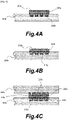
- FIG. 4 is a schematic sectional view showing various modified examples of the separator-integrated gasket according to the first embodiment of the present disclosure.
- Fig. 4A is a sectional view showing a separator-integrated gasket acquired by providing a plurality of uneven parts 203a having a rectangular cross-section on the surface of a separator 200a and molding a gasket 210a integrally with the portion where the uneven parts 203a are formed.
- a welded portion 215a is formed along the uneven parts 203a, enabling an increase in the surface area of the welded portion 215a between the separator 200a and the gasket 210a, and as a result, the fixing force can be increased.
- Fig. 4B is a sectional view showing a separator-integrated gasket acquired by providing a plurality of uneven parts 203b having a substantially arc-shaped cross-section on the surface of a separator 200b and molding a gasket 210b integrally with the uneven parts 203b.
- a welded portion 215b is formed along the uneven parts 203b, enabling an increase in the surface area of the welded portion 215b between the separator 200b and the gasket 210b, and as a result, the fixing force can be increased.
- the cell stack may have locations, in a region where the coolant flows, where the separators are provided adjacent to each other rather than via the MEA.
- a gasket is to be provided between the separators to prevent the coolant from leaking.
- a single gasket may be provided integrally with a pair of separators.
- Fig. 4C is a sectional view showing a separator-integrated gasket in which a single gasket 210c is provided integrally with a pair of separators 200c.
- a plurality of uneven parts 203c may be provided on each of the separators 200c, and the gasket 210c may be provided integrally with the uneven parts 203c.
- welded portions 215c are formed along the uneven parts 203c, enabling an increase in the surface area of the welded portions 215c between the separators 200c and the gasket 210c, and as a result, the fixing force can be increased.
- Fig. 5 shows a second embodiment of the present disclosure.
- a configuration in which the material of the gasket differs from the first embodiment will be illustrated. All other basic configurations and actions are identical to the first embodiment, and therefore identical constituent parts have been allocated identical reference symbols, and description thereof has been omitted as appropriate.
- Fig. 5 is an illustrative view of a separator-integrated gasket according to the second embodiment of the present disclosure.
- Fig. 5A is a partially enlarged sectional view of the configuration of the first embodiment, described above.
- Fig. 5B is a partially enlarged sectional view of the separator-integrated gasket according to the second embodiment of the present disclosure.
- Fig. 5C is a sectional view showing an action of the separator-integrated gasket according to the second embodiment of the present disclosure.
- the gasket 210 formed from the second resin material and the separator 200 formed mainly from carbon have different thermal expansion coefficients. Therefore, when the temperatures of the separator 200 and the gasket 210 decrease after the gasket 210 is molded integrally with the separator 200, the gasket 210 contracts by a larger amount than the separator 200. Hence, due to the contraction of the gasket 210 (see the arrows in Fig. 5A ), a force for causing the separator 200 to contract acts on the separator 200. As a result, depending on the dimensions, shapes, and so on of the separator 200 and the gasket 210, a part of the separator 200 may deform so as to become bent.
- the separator-integrated gasket according to this embodiment similarly to the first embodiment, has the separator 200 and a gasket 210S. Further, the separator 200 and the gasket 210S are fixed integrally by the welded portion 215. Note that the configuration of the separator 200 is similar to the first embodiment, and therefore description thereof has been omitted.
- the material of the gasket 210S is constituted by a mixed material of a rubber material and the thermoplastic second resin material that is compatible with the first resin material.
- PP polypropylene
- PE polyethylene
- EPDM polyethylene
- a molding material can be obtained by kneading a material formed by dry-blending the second resin material and the rubber material at a desired ratio in a biaxial extrusion kneader. Note that when the gasket 210S is integrally molded with the separator 200 by injection molding, the kneaded molding material described above may be used in pellet form.
- this embodiment differs from the first embodiment only in the material of the gasket 210S.
- a manufacturing method for the separator-integrated gasket according to this embodiment is also similar to the first embodiment, and therefore description thereof has been omitted.
- the material of the gasket 210S is constituted by a mixed material of the second resin material and a rubber material. Therefore, the gasket 210S expands and contracts more easily than the gasket 210 of the first embodiment. Accordingly, deformation of the separator 200 due to thermal contraction of the gasket 210S can be suppressed. Furthermore, a stable sealing function can be achieved regardless of variation in a gap formed in the part where the gasket 210S is disposed. More specifically, as shown in Fig.
- the gasket 210S illustrated in this embodiment can also be applied to the various modified examples shown in Fig. 4 .
Landscapes
- Engineering & Computer Science (AREA)
- Manufacturing & Machinery (AREA)
- Life Sciences & Earth Sciences (AREA)
- Sustainable Development (AREA)
- Sustainable Energy (AREA)
- Chemical & Material Sciences (AREA)
- Chemical Kinetics & Catalysis (AREA)
- Electrochemistry (AREA)
- General Chemical & Material Sciences (AREA)
- General Engineering & Computer Science (AREA)
- Mechanical Engineering (AREA)
- Fuel Cell (AREA)
Applications Claiming Priority (3)
| Application Number | Priority Date | Filing Date | Title |
|---|---|---|---|
| JP2020018626 | 2020-02-06 | ||
| JP2020139437 | 2020-08-20 | ||
| PCT/JP2020/048735 WO2021157252A1 (ja) | 2020-02-06 | 2020-12-25 | セパレータ一体ガスケット及びその製造方法 |
Publications (4)
| Publication Number | Publication Date |
|---|---|
| EP4101618A1 true EP4101618A1 (de) | 2022-12-14 |
| EP4101618A4 EP4101618A4 (de) | 2025-04-02 |
| EP4101618B1 EP4101618B1 (de) | 2025-10-29 |
| EP4101618C0 EP4101618C0 (de) | 2025-10-29 |
Family
ID=77200094
Family Applications (1)
| Application Number | Title | Priority Date | Filing Date |
|---|---|---|---|
| EP20917705.4A Active EP4101618B1 (de) | 2020-02-06 | 2020-12-25 | Dichtung mit integriertem separator und herstellungsverfahren dafür |
Country Status (5)
| Country | Link |
|---|---|
| US (1) | US20220399551A1 (de) |
| EP (1) | EP4101618B1 (de) |
| JP (1) | JP7357702B2 (de) |
| CN (1) | CN114641878B (de) |
| WO (1) | WO2021157252A1 (de) |
Families Citing this family (1)
| Publication number | Priority date | Publication date | Assignee | Title |
|---|---|---|---|---|
| JP7724052B2 (ja) * | 2020-07-22 | 2025-08-15 | ロベルト・ボッシュ・ゲゼルシャフト・ミト・ベシュレンクテル・ハフツング | サブガスケットの製造方法及び製造システム |
Family Cites Families (23)
| Publication number | Priority date | Publication date | Assignee | Title |
|---|---|---|---|---|
| JPH0911246A (ja) * | 1995-07-03 | 1997-01-14 | Kanto Auto Works Ltd | 内装材の製造方法 |
| JP2001118592A (ja) * | 1999-10-18 | 2001-04-27 | Matsushita Electric Ind Co Ltd | 高分子電解質型燃料電池及び電池スタック |
| EP1453127A3 (de) * | 2003-01-30 | 2006-07-19 | Matsushita Electric Industrial Co., Ltd. | Polymerelektrolytbrennstoffzelle, ein Vorprodukt davon und eine Herstellungsmethode |
| EP1667264A4 (de) * | 2003-07-08 | 2008-05-21 | Freudenberg Carl Kg | Trennglied für eine brennstoffbatterie |
| JP4211567B2 (ja) * | 2003-10-20 | 2009-01-21 | Nok株式会社 | 固体高分子形燃料電池用セパレータ |
| JP2006022900A (ja) * | 2004-07-08 | 2006-01-26 | Nhk Spring Co Ltd | ガスケット材、ガスケット材の製造方法およびガスケットの取り付け方法 |
| JP2006032075A (ja) * | 2004-07-15 | 2006-02-02 | Nok Corp | 燃料電池用構成部品 |
| JP2006054121A (ja) * | 2004-08-12 | 2006-02-23 | Fuiisa Kk | 燃料電池用セパレータ及びその製造方法 |
| KR101270856B1 (ko) * | 2005-04-01 | 2013-06-05 | 파나소닉 주식회사 | Mea, mea의 제조방법 및 고분자 전해질형 연료 전지 |
| US20080206622A1 (en) * | 2006-06-06 | 2008-08-28 | Naoki Mitsuta | Sealing member for fuel cell, method for producing the same and separator for fuel cell |
| JP5068051B2 (ja) * | 2006-09-29 | 2012-11-07 | 昭和電工株式会社 | 燃料電池用セパレータおよびその製造方法 |
| JP5068052B2 (ja) * | 2006-09-29 | 2012-11-07 | 昭和電工株式会社 | 燃料電池用セパレータ、燃料電池用セルおよび燃料電池用セルユニット、ならびに燃料電池用セパレータおよび燃料電池用セルユニットの製造方法 |
| JP5177619B2 (ja) | 2007-01-18 | 2013-04-03 | Nok株式会社 | 燃料電池用ガスケット一体部品の製造方法 |
| JP5224035B2 (ja) | 2008-02-12 | 2013-07-03 | Nok株式会社 | シール構造体の製造方法 |
| JP5725277B2 (ja) | 2010-06-14 | 2015-05-27 | Nok株式会社 | ガスケット |
| JP5803772B2 (ja) * | 2012-03-27 | 2015-11-04 | 宇部興産機械株式会社 | インサート成形方法 |
| JP5979562B2 (ja) * | 2012-05-17 | 2016-08-24 | パナソニックIpマネジメント株式会社 | 燃料電池及びその製造方法 |
| JP6250837B2 (ja) * | 2015-03-31 | 2017-12-20 | 本田技研工業株式会社 | 燃料電池用セパレータ及びその製造方法 |
| JP6495106B2 (ja) * | 2015-06-04 | 2019-04-03 | Nok株式会社 | ガスケット及びその製造方法 |
| JP2017027663A (ja) * | 2015-07-15 | 2017-02-02 | 住友電気工業株式会社 | レドックスフロー電池 |
| KR20190005860A (ko) * | 2016-05-10 | 2019-01-16 | 엔오케이 가부시키가이샤 | 개스킷 및 그 장착방법 |
| JP6973029B2 (ja) | 2017-12-20 | 2021-11-24 | トヨタ自動車株式会社 | 燃料電池用のセパレータの製造方法およびセパレータ素材 |
| JP2019190604A (ja) | 2018-04-27 | 2019-10-31 | Nok株式会社 | Gdl一体ガスケット及びその製造方法 |
-
2020
- 2020-12-25 WO PCT/JP2020/048735 patent/WO2021157252A1/ja not_active Ceased
- 2020-12-25 EP EP20917705.4A patent/EP4101618B1/de active Active
- 2020-12-25 CN CN202080077138.5A patent/CN114641878B/zh active Active
- 2020-12-25 US US17/775,689 patent/US20220399551A1/en active Pending
- 2020-12-25 JP JP2021575660A patent/JP7357702B2/ja active Active
Also Published As
| Publication number | Publication date |
|---|---|
| JP7357702B2 (ja) | 2023-10-06 |
| EP4101618B1 (de) | 2025-10-29 |
| CN114641878A (zh) | 2022-06-17 |
| CN114641878B (zh) | 2024-08-06 |
| JPWO2021157252A1 (de) | 2021-08-12 |
| US20220399551A1 (en) | 2022-12-15 |
| EP4101618A4 (de) | 2025-04-02 |
| EP4101618C0 (de) | 2025-10-29 |
| WO2021157252A1 (ja) | 2021-08-12 |
Similar Documents
| Publication | Publication Date | Title |
|---|---|---|
| KR101270856B1 (ko) | Mea, mea의 제조방법 및 고분자 전해질형 연료 전지 | |
| US10044047B2 (en) | Electrode-membrane-frame assembly, method for producing the same, and fuel cell | |
| US8298716B2 (en) | Method of manufacturing seal-integrated type membrane electrode assembly | |
| US20040234831A1 (en) | Electrolyte membrane for a fuel cell, electrolyte membrane electrode assembly for a fuel cell, and a fuel cell | |
| JP3897808B2 (ja) | Mea、meaの製造方法及び高分子電解質形燃料電池 | |
| US20150295210A1 (en) | Base material integrated type seal and metal mold for manufacturing the same | |
| US9136546B2 (en) | Fuel cell stack, manufacturing method of fuel cell stack and replacement method of module as constituent of fuel cell stack | |
| JP5310976B2 (ja) | 燃料電池の密封構造 | |
| EP4101618B1 (de) | Dichtung mit integriertem separator und herstellungsverfahren dafür | |
| EP3174143B1 (de) | Herstellungsverfahren für plattenintegrierte dichtung | |
| US20180123158A1 (en) | Fuel cell stack | |
| JP2017117759A (ja) | 高分子電解質型燃料電池 | |
| JP7478557B2 (ja) | セパレータ一体ガスケット | |
| JP2016095902A (ja) | 燃料電池及びその製造方法 | |
| EP2686902B1 (de) | Verbindungsverfahren und -anordnung für brennstoffzellenplatten | |
| JP2006164659A (ja) | 燃料電池セル | |
| EP4379873A1 (de) | Brennstoffzellenanordnung und herstellungsverfahren für die brennstoffzellenanordnung | |
| JP5273369B2 (ja) | シール構造体の製造方法 | |
| EP2873106B1 (de) | Brennstoffzellenelektrodenbaugruppe | |
| JP2010192239A (ja) | 膜電極接合体、燃料電池、及び膜電極接合体の製造方法 |
Legal Events
| Date | Code | Title | Description |
|---|---|---|---|
| STAA | Information on the status of an ep patent application or granted ep patent |
Free format text: STATUS: THE INTERNATIONAL PUBLICATION HAS BEEN MADE |
|
| PUAI | Public reference made under article 153(3) epc to a published international application that has entered the european phase |
Free format text: ORIGINAL CODE: 0009012 |
|
| STAA | Information on the status of an ep patent application or granted ep patent |
Free format text: STATUS: REQUEST FOR EXAMINATION WAS MADE |
|
| 17P | Request for examination filed |
Effective date: 20220512 |
|
| AK | Designated contracting states |
Kind code of ref document: A1 Designated state(s): AL AT BE BG CH CY CZ DE DK EE ES FI FR GB GR HR HU IE IS IT LI LT LU LV MC MK MT NL NO PL PT RO RS SE SI SK SM TR |
|
| DAV | Request for validation of the european patent (deleted) | ||
| DAX | Request for extension of the european patent (deleted) | ||
| A4 | Supplementary search report drawn up and despatched |
Effective date: 20250304 |
|
| RIC1 | Information provided on ipc code assigned before grant |
Ipc: H01M 8/0286 20160101ALI20250226BHEP Ipc: H01M 8/0284 20160101ALI20250226BHEP Ipc: H01M 8/0276 20160101ALI20250226BHEP Ipc: H01M 8/0273 20160101ALI20250226BHEP Ipc: H01M 8/0271 20160101ALI20250226BHEP Ipc: F16J 15/10 20060101ALI20250226BHEP Ipc: B29C 45/14 20060101AFI20250226BHEP |
|
| GRAP | Despatch of communication of intention to grant a patent |
Free format text: ORIGINAL CODE: EPIDOSNIGR1 |
|
| STAA | Information on the status of an ep patent application or granted ep patent |
Free format text: STATUS: GRANT OF PATENT IS INTENDED |
|
| INTG | Intention to grant announced |
Effective date: 20250717 |
|
| GRAS | Grant fee paid |
Free format text: ORIGINAL CODE: EPIDOSNIGR3 |
|
| GRAA | (expected) grant |
Free format text: ORIGINAL CODE: 0009210 |
|
| STAA | Information on the status of an ep patent application or granted ep patent |
Free format text: STATUS: THE PATENT HAS BEEN GRANTED |
|
| AK | Designated contracting states |
Kind code of ref document: B1 Designated state(s): AL AT BE BG CH CY CZ DE DK EE ES FI FR GB GR HR HU IE IS IT LI LT LU LV MC MK MT NL NO PL PT RO RS SE SI SK SM TR |
|
| REG | Reference to a national code |
Ref country code: CH Ref legal event code: F10 Free format text: ST27 STATUS EVENT CODE: U-0-0-F10-F00 (AS PROVIDED BY THE NATIONAL OFFICE) Effective date: 20251029 Ref country code: GB Ref legal event code: FG4D |
|
| REG | Reference to a national code |
Ref country code: DE Ref legal event code: R096 Ref document number: 602020061459 Country of ref document: DE |
|
| REG | Reference to a national code |
Ref country code: IE Ref legal event code: FG4D |
|
| U01 | Request for unitary effect filed |
Effective date: 20251030 |
|
| U07 | Unitary effect registered |
Designated state(s): AT BE BG DE DK EE FI FR IT LT LU LV MT NL PT RO SE SI Effective date: 20251105 |
|
| PGFP | Annual fee paid to national office [announced via postgrant information from national office to epo] |
Ref country code: GB Payment date: 20251218 Year of fee payment: 6 |
|
| U20 | Renewal fee for the european patent with unitary effect paid |
Year of fee payment: 6 Effective date: 20251222 |
|
| PG25 | Lapsed in a contracting state [announced via postgrant information from national office to epo] |
Ref country code: ES Free format text: LAPSE BECAUSE OF FAILURE TO SUBMIT A TRANSLATION OF THE DESCRIPTION OR TO PAY THE FEE WITHIN THE PRESCRIBED TIME-LIMIT Effective date: 20251029 |
|
| PG25 | Lapsed in a contracting state [announced via postgrant information from national office to epo] |
Ref country code: NO Free format text: LAPSE BECAUSE OF FAILURE TO SUBMIT A TRANSLATION OF THE DESCRIPTION OR TO PAY THE FEE WITHIN THE PRESCRIBED TIME-LIMIT Effective date: 20260129 |
|
| PG25 | Lapsed in a contracting state [announced via postgrant information from national office to epo] |
Ref country code: HR Free format text: LAPSE BECAUSE OF FAILURE TO SUBMIT A TRANSLATION OF THE DESCRIPTION OR TO PAY THE FEE WITHIN THE PRESCRIBED TIME-LIMIT Effective date: 20251029 |
|
| PG25 | Lapsed in a contracting state [announced via postgrant information from national office to epo] |
Ref country code: RS Free format text: LAPSE BECAUSE OF FAILURE TO SUBMIT A TRANSLATION OF THE DESCRIPTION OR TO PAY THE FEE WITHIN THE PRESCRIBED TIME-LIMIT Effective date: 20260129 |
|
| PG25 | Lapsed in a contracting state [announced via postgrant information from national office to epo] |
Ref country code: IS Free format text: LAPSE BECAUSE OF FAILURE TO SUBMIT A TRANSLATION OF THE DESCRIPTION OR TO PAY THE FEE WITHIN THE PRESCRIBED TIME-LIMIT Effective date: 20260228 |
|
| PG25 | Lapsed in a contracting state [announced via postgrant information from national office to epo] |
Ref country code: PL Free format text: LAPSE BECAUSE OF FAILURE TO SUBMIT A TRANSLATION OF THE DESCRIPTION OR TO PAY THE FEE WITHIN THE PRESCRIBED TIME-LIMIT Effective date: 20251029 |