EP4100285B1 - Straffvorrichtung für eine sicherheitsgurtkomponente - Google Patents
Straffvorrichtung für eine sicherheitsgurtkomponente Download PDFInfo
- Publication number
- EP4100285B1 EP4100285B1 EP21701232.7A EP21701232A EP4100285B1 EP 4100285 B1 EP4100285 B1 EP 4100285B1 EP 21701232 A EP21701232 A EP 21701232A EP 4100285 B1 EP4100285 B1 EP 4100285B1
- Authority
- EP
- European Patent Office
- Prior art keywords
- guide
- tension cable
- guide block
- piston
- tensioning
- Prior art date
- Legal status (The legal status is an assumption and is not a legal conclusion. Google has not performed a legal analysis and makes no representation as to the accuracy of the status listed.)
- Active
Links
Images
Classifications
-
- B—PERFORMING OPERATIONS; TRANSPORTING
- B60—VEHICLES IN GENERAL
- B60R—VEHICLES, VEHICLE FITTINGS, OR VEHICLE PARTS, NOT OTHERWISE PROVIDED FOR
- B60R22/00—Safety belts or body harnesses in vehicles
- B60R22/18—Anchoring devices
- B60R22/195—Anchoring devices with means to tension the belt in an emergency, e.g. means of the through-anchor or splitted reel type
-
- B—PERFORMING OPERATIONS; TRANSPORTING
- B60—VEHICLES IN GENERAL
- B60R—VEHICLES, VEHICLE FITTINGS, OR VEHICLE PARTS, NOT OTHERWISE PROVIDED FOR
- B60R22/00—Safety belts or body harnesses in vehicles
- B60R22/34—Belt retractors, e.g. reels
- B60R22/46—Reels with means to tension the belt in an emergency by forced winding up
- B60R22/4628—Reels with means to tension the belt in an emergency by forced winding up characterised by fluid actuators, e.g. pyrotechnic gas generators
-
- B—PERFORMING OPERATIONS; TRANSPORTING
- B60—VEHICLES IN GENERAL
- B60R—VEHICLES, VEHICLE FITTINGS, OR VEHICLE PARTS, NOT OTHERWISE PROVIDED FOR
- B60R22/00—Safety belts or body harnesses in vehicles
- B60R22/18—Anchoring devices
- B60R22/195—Anchoring devices with means to tension the belt in an emergency, e.g. means of the through-anchor or splitted reel type
- B60R22/1952—Transmission of tensioning power by cable; Return motion locking means therefor
-
- B—PERFORMING OPERATIONS; TRANSPORTING
- B60—VEHICLES IN GENERAL
- B60R—VEHICLES, VEHICLE FITTINGS, OR VEHICLE PARTS, NOT OTHERWISE PROVIDED FOR
- B60R22/00—Safety belts or body harnesses in vehicles
- B60R22/18—Anchoring devices
- B60R22/195—Anchoring devices with means to tension the belt in an emergency, e.g. means of the through-anchor or splitted reel type
- B60R22/1954—Anchoring devices with means to tension the belt in an emergency, e.g. means of the through-anchor or splitted reel type characterised by fluid actuators, e.g. pyrotechnic gas generators
- B60R22/1955—Linear actuators
Definitions
- the present invention relates to a tensioning device for a safety belt component, with a gas generator for generating a compressed gas, a piston that can be driven by the compressed gas, a traction cable connected to the piston, which can be connected to a safety belt component that is to be set in a tensioning movement, a tensioning tube that receives and guides the piston, and a guide block that forms a cable guide, in which a receptacle that receives the gas generator and a pressure chamber that is fluidically connected to the receptacle are formed, wherein the guide block is connected to the tensioning tube and the traction cable runs straight in a piston movement direction from the tensioning tube through the pressure chamber.
- Such a tensioning device is made, for example, of EN 10 2015 111 083 B4 known, in which the guide block forms a cable deflection, so that the tension from the pressure chamber in the direction of the seat belt component to be tightened is deflected by a deflection guide in the guide block transversely to the piston movement direction.
- a deflection of the traction cable by the guide block was previously necessary, since the tensioning device is mounted laterally next to a vehicle seat and the piston movement direction is aligned parallel to the longitudinal axis of the vehicle, whereby The tensioning cable is usually tightened by a belt buckle or an end fitting of a safety belt.
- the need has now arisen for the tensioning device to be mounted in a different orientation in the motor vehicle.
- a tensioning device with the features of the preamble of claim 1 is known from US$5,364,129
- Other tensioning devices are known from DE 297 08 880 U1 , DE 102 50 499 A1 and EP 1 737 711 A1 known.
- the object of the present invention is therefore to provide a tensioning device which can be mounted with a different orientation in the motor vehicle and/or which allows greater flexibility in the configuration of the tensioning device.
- the object is achieved in particular by a tensioning device with the features mentioned at the outset, in which the guide block forms a linear guide adjoining the pressure chamber, which is designed in such a way that the traction cable can be guided out of the guide block parallel to the direction of piston movement on the side opposite the tensioning tube.
- the one-piece guide block is designed in such a way that the tension cable emerges from the guide block parallel to or offset parallel to the direction of piston movement, so that the tensioning tube that determines the direction of piston movement can be aligned parallel or offset parallel to the tensioning movement of the seat belt component.
- the tension cable it is possible for the tension cable to be redirected outside the guide block using other means.
- the tensioning device can therefore be placed in other places in the motor vehicle than previously usual.
- the invention provides that the linear guide has at least one resistance element, which is arranged in particular in the linear guide, wherein the resistance element counteracts an unintentional movement of the traction cable. It is provided that projections or constrictions are formed in the guide block outside the pressure chamber into the linear guide, which prevent a relative movement of the traction cable and thus of the piston relative to the tensioning tube before assembly or after assembly in the motor vehicle.
- the resistance element it is possible for the resistance element to be formed as a single piece on the guide block. However, it is preferred that the resistance element is formed as an independent component and is inserted into the linear guide formed by the guide block.
- the independent component is made of a different material than the guide block.
- the component used is preferably made of a plastic, wherein the at least one resistance element formed by the component is reduced at the beginning of a tightening process due to the friction between the traction cable and the at least one resistance element.
- the at least one resistance element formed by the component is reduced at the beginning of a tightening process due to the friction between the traction cable and the at least one resistance element.
- projections that initially come into contact with the traction cable can be formed on the component made of plastic, which prevent unintentional movement of the traction cable, but are reduced in height at the beginning of the tightening process due to the friction with the traction cable, so that their resistance is reduced.
- Such an independent component is particularly useful when the traction cable is led out of the guide block parallel and aligned with the direction of piston movement.
- a further resistance element can also be formed by creating a chicane for the traction cable through the guide block itself or through a component inserted into the guide block.
- the resistance element can form an S-shaped Design a guide for the pull cable so that the pull cable exits the guide block with a parallel offset to the direction of piston movement.
- the guide block can not only be used for a new arrangement of the tensioning device, but can also be used as a guide block in already known tensioning devices, it can be provided that in addition to the linear guide, a deflection guide is formed in the guide block, which is designed such that the traction cable can be guided out of the guide block at an angle to the direction of piston movement. Both a linear guide and a deflection guide are therefore formed in the guide block, so that the guide block can be used flexibly.
- the guide block can be designed such that the deflection guide branches off from the linear guide and in particular enables a cable deflection of more than 20°, preferably more than 45° and particularly preferably more than 90°.
- the independent component is shaped in such a way that it is arranged both in the linear guide and in the deflection guide. In this way, a position of the component in the guide block is also reliably specified and movement of the independent component is prevented.
- the independent component is designed in such a way that it extends along the linear guide with the section forming the resistance elements, while a holding section engages in the deflection guide.
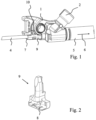
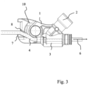
- the tensioning devices shown each comprise a guide block 1 in which a receptacle 2 is formed for a gas generator (not shown).
- the receptacle 2 is fluidically connected to a pressure chamber 3 formed in the guide block 1.
- a traction cable 4 is guided straight through the pressure chamber 3 and into a tensioning tube 5. Inside the tensioning tube 5, the traction cable 4 is connected to a piston (not shown).
- the arrangement of the piston on the traction cable and in the tensioning tube is already described in the above-mentioned EN 10 2015 111 083 B4 mentioned, to which reference is made in this regard. However, the arrangement of the piston is not important for the present invention.
- the gas generator In the event of activation, the gas generator produces a compressed gas which is passed through the pressure chamber 3 into the tensioner tube 5 and drives the piston and thus also the traction cable 4 in a piston movement direction 6.
- the guide block 1 On the side facing away from the tensioner tube 5, the guide block 1 is designed in such a way that the traction cable 4 is aligned parallel ( Figure 1 ) or with a parallel offset ( Figure 3 ) is led out of the guide block 1.
- the guide block 1 therefore has a linear guide 7.
- the guide block 1 also has a deflection guide 10, so that the traction cable 4 could also be led out of the guide block 1 transversely to the piston movement direction 6 (not shown in the figures).
- a resistance element 8 is provided.
- the resistance element 8 is formed by projections on an independent component 9.
- the independent component 9 is shaped in such a way that it is arranged with a holding section in the deflection guide 10 and with the section having the resistance element 8 in the linear guide 7.
- the projections on the individual component 9 are reduced in height due to the friction with the traction cable 4, so that the friction or the resistance also decreases.
- the resistance element 8 is formed by a kind of chicane, so that the traction cable 4 is deflected in an S-shape, which creates a resistance.
Landscapes
- Engineering & Computer Science (AREA)
- Mechanical Engineering (AREA)
- Automotive Seat Belt Assembly (AREA)
Description
- Die vorliegende Erfindung betrifft einen Straffvorrichtung für eine Sicherheitsgurtkomponente, mit einem Gasgenerator zur Erzeugung eines Druckgases, einem von dem Druckgas antreibbaren Kolben, einem an den Kolben angeschlossenen Zugseil, welches mit einer in eine Straffbewegung zu versetzenden Sicherheitsgurtkomponente verbindbar ist, einem den Kolben aufnehmenden und führenden Strafferrohr und einem eine Seilführung ausbildenden Führungsblock, in dem eine den Gasgenerator aufnehmende Aufnahme und eine mit der Aufnahme strömumgstechnisch verbundene Druckkammer ausgebildet ist, wobei der Führungsblock mit dem Strafferrohr verbunden ist und das Zugseil geradlinig in einer Kolbenbewegungsrichtung aus dem Strafferrohr durch die Druckkammer verläuft.
- Eine solche Straffvorrichtung ist beispielsweise aus
DE 10 2015 111 083 B4 bekannt, bei der der Führungsblock eine Seilumlenkung ausbildet, so dass das aus der Druckkammer in Richtung der zu straffenden Sicherheitsgurtkomponente von einer Umlenkungsführung in dem Führungsblock quer zu der Kolbenbewegungsrichtung umgelenkt wird. Eine solche Umlenkung des Zugseiles durch den Führungsblock war bisher erforderlich, da die Straffvorrichtung seitlich neben einem Fahrzeugsitz montiert wird und die Kolbenbewegungsrichtung parallel zur Längsachse des Fahrzeuges ausgerichtet ist, wobei über das Zugseil in der Regel ein Gurtschloss oder ein Endbeschlag eines Sicherheitsgurtes gestrafft wird. Es hat sich nun der Bedarf entwickelt, dass die Straffvorrichtung auch in anderer Ausrichtung im Kraftfahrzeug montiert wird. Eine Straffvorrichtung mit den Merkmalen des Oberbegriffs des Anspruchs 1 ist ausUS 5,364,129 bekannt. Weitere Straffvorrichtung sind ausDE 297 08 880 U1 ,DE 102 50 499 A1 undEP 1 737 711 A1 bekannt. - Aufgabe der vorliegenden Erfindung ist es daher, eine Straffvorrichtung bereitzustellen, die mit einer anderen Ausrichtung im Kraftfahrzeug montiert werden kann und/oder die eine höhere Flexibilität bei der Konfiguration der Straffvorrichtung ermöglicht.
- Gelöst wird die Aufgabe durch eine Straffvorrichtung mit den Merkmalen des unabhängigen Anspruchs. Vorteilhafte Weiterbildungen der Straffvorrichtung sind in den abhängigen Ansprüchen und in der Beschreibung angegeben, wobei einzelne Merkmale der vorteilhaften Weiterbildungen in technisch sinnvoller Weise miteinander kombinierbar sind.
- Gelöst wird die Aufgabe insbesondere durch eine Straffvorrichtung mit den eingangs genannten Merkmalen, bei der der Führungsblock eine sich an die Druckkammer anschließende Linearführung ausbildet, die derart gestaltet ist, dass das Zugseil parallel zu der Kolbenbewegungsrichtung auf der dem Strafferrohr gegenüberliegenden Seite aus dem Führungsblock herausführbar ist.
- Die Erfindung sieht in ihrem Grundgedanken also vor, dass der einteilige Führungsblock derart ausgebildet ist, dass das Zugseil parallel fluchtend oder parallel versetzt zu der Kolbenbewegungsrichtung aus dem Führungsblock heraustritt, so dass das die Kolbenbewegungsrichtung vorgebende Strafferrohr parallel oder parallel versetzt zu der Straffbewegung der Sicherheitsgurtkomponente ausgerichtet werden kann. Alternativ ist es möglich, dass eine Umlenkung des Zugseiles außerhalb des Führungsblockes mit weiteren Mitteln erfolgt. Somit kann die Straffvorrichtung also an anderen Orten als bisher üblich im Kraftfahrzeug platziert werden.
- Um zu verhindern, dass das Zugseil nach dem Zusammenbau der Straffvorrichtung und vor oder auch nach der Montage der Straffvorrichtung im Kraftfahrzeug unbeabsichtigt bewegt wird und somit auch der Kolben im Strafferrohr eine nicht gewünschte Stellung einnimmt, ist erfindungsgemäß vorgesehen, dass die Linearführung mindestens ein Widerstandselement aufweist, welches insbesondere in der Linearführung angeordnet ist, wobei das Widerstandselement einer unbeabsichtigten Bewegung des Zugseiles entgegenwirkt. Es ist vorgesehen, dass in dem Führungsblock außerhalb der Druckkammer in die Linearführung vorspringende Vorsprünge oder Verengungen ausgebildet sind, die eine Relativbewegung des Zugseiles und damit des Kolbens relativ zum Strafferrohr vor der Montage oder auch nach der Montage im Kraftfahrzeug verhindern.
- Prinzipiell ist es möglich, dass das Widerstandselement einteilig an dem Führungsblock ausgebildet ist. Bevorzugt ist jedoch, dass das Widerstandselement als eigenständiges Bauteil ausgebildet ist und in die durch den Führungsblock ausgebildete Linearführung eingesetzt ist. Das eigenständige Bauteil ist dabei aus einem anderen Material gefertigt als der Führungsblock.
- Das eingesetzte Bauteil ist bevorzugt aus einem Kunststoff ausgebildet, wobei das von dem Bauteil ausgebildete mindestens eine Widerstandselemente am Anfang eines Straffvorganges aufgrund der Reibung zwischen dem Zugseil und dem mindestens einen Widerstandselement reduziert werden. Beispielsweise können an dem aus Kunststoff gebildeten Bauteil zunächst mit dem Zugseil in Anlage befindliche Vorsprünge ausgebildet sein, die eine unbeabsichtigte Bewegung des Zugseiles verhindern, am Anfang des Straffvorgangs aufgrund der Reibung mit dem Zugseil aber in ihrer Höhe reduziert werden, so dass sich deren Widerstand verringert. Ein solches eigenständiges Bauteil ist insbesondere dann sinnvoll, wenn das Zugseil parallel fluchtend zu der Kolbenbewegungsrichtung aus dem Führungsblock herausgeführt ist.
- Ein weiteres Widerstandselement kann aber auch dadurch gebildet werden, dass eine Schikane für das Zugseil durch den Führungsblock selbst oder durch ein in den Führungsblock eingesetztes Bauteil erzeugt wird. Insbesondere kann das Widerstandselement durch den Führungsblock bzw. dessen Linearführung eine S-förmige Führung für das Zugseil ausbilden, sodass das Zugseil mit einem parallelen Versatz zu der Kolbenbewegungsrichtung aus dem Führungsblock austritt.
- Damit der Führungsblock nicht nur für eine neuartige Anordnung der Straffvorrichtung eingesetzt werden kann, sondern auch in bereits bekannten Straffvorrichtungen als Führungsblock verwendet werden kann, kann vorgesehen sein, dass zusätzlich zu der Linearführung eine Umlenkungsführung in dem Führungsblock ausgebildet ist, die derart gestaltet ist, dass das Zugseil schräg zu der Kolbenbewegungsrichtung aus dem Führungsblock herausführbar ist. In dem Führungsblock ist also sowohl eine Linearführung als auch eine Umlenkungsführung ausgebildet, so dass der Führungsblock flexibel eingesetzt werden kann. Insbesondere kann der Führungsblock so ausgebildet sein, dass die Umlenkungsführung aus der Linearführung abzweigt und insbesondere eine Seilumlenkung von mehr als 20°, bevorzugt mehr als 45° und besonders bevorzugt von mehr als 90° ermöglicht.
- Wenn das Widerstandselement an einem eigenständigen Bauteil ausgebildet ist, kann vorgesehen sein, dass das eigenständige Bauteil so geformt ist, dass es sowohl in der Linearführung als auch in der Umlenkungsführung angeordnet ist. Auf diese Weise wird auch zuverlässig eine Position des Bauteils in dem Führungsblock vorgegeben und eine Bewegung des eigenständigen Bauteils verhindert. Insbesondere ist das eigenständige Bauteil so ausgebildet, dass es sich mit dem die Widerstandselemente bildenden Abschnitt entlang der Linearführung erstreckt, während ein Halteabschnitt in die Umlenkungsführung eingreift.
- Die Erfindung sowie das technische Umfeld werden im Folgenden anhand der Figuren beispielhaft erläutert. Es zeigen schematisch
- Figur 1:
- eine Straffvorrichtung,
- Figur 2:
- ein eigenständiges Bauteil zur Ausbildung eines Widerstandselements der Straffvorrichtung gemäß
Figur 1 und - Figur 3:
- eine schematische Darstellung einer weiteren Ausführungsform einer Straffvorrichtung.
- Die in den
Figuren 1 und3 dargestellten Straffvorrichtungen umfassen jeweils einen Führungsblock 1, in dem eine Aufnahme 2 für einen nicht dargestellten Gasgenerator ausgebildet ist. Die Aufnahme 2 ist strömungstechnisch mit einer in dem Führungsblock 1 ausgebildeten Druckkammer 3 verbunden. - Ein Zugseil 4 ist geradlinig durch die Druckkammer 3 und in ein Strafferrohr 5 geführt. Innerhalb des Strafferrohrs 5 ist das Zugseil 4 mit einem nicht dargestellten Kolben verbunden. Die Anordnung des Kolbens an dem Zugseil und in dem Strafferrohr ist bereits in der eingangs erwähnten
DE 10 2015 111 083 B4 erwähnt, auf die diesbezüglich verwiesen wird. Auf die Anordnung des Kolbens kommt es für die vorliegende Erfindung aber auch nicht an. - Im Auslösefall wird von dem Gasgenerator ein Druckgas erzeugt, dass durch die Druckkammer 3 in das Strafferrohr 5 geleitet wird und dort den Kolben und somit auch das Zugseil 4 in eine Kolbenbewegungsrichtung 6 antreibt.
- Auf der dem Strafferrohr 5 abgewandten Seite ist der Führungsblock 1 derart ausgebildet, dass das Zugseil 4 parallel fluchtend (
Figur 1 ) beziehungsweise mit einem parallelen Versatz (Figur 3 ) aus dem Führungsblock 1 herausgeführt ist. Der Führungsblock 1 weist also eine Linearführung 7 auf. Zusätzlich weißt der Führungsblock 1 auch eine Umlenkungsführung 10 auf, so dass das Zugseil 4 auch quer zu der Kolbenbewegungsrichtung 6 aus dem Führungsblock 1 herausgeführt werden könnte (in den Figuren nicht dargestellt). - Um zu verhindern, dass das Zugseil 4 und damit der Kolben vor einem Straffvorgang unbeabsichtigt bewegt werden, ist ein Widerstandselement 8 vorgesehen.
- Gemäß der Ausführungsform der
Figuren 1 und 2 ist das Widerstandselement 8 durch Vorsprünge an einem eigenständigen Bauteil 9 ausgebildet. Das eigenständige Bauteil 9 ist so geformt, dass es mit einem Halteabschnitt in der Umlenkungsführung 10 angeordnet ist und mit dem das Widerstandselement 8 aufweisenden Abschnitt in der Linearführung 7. Am Anfang eines durch den Gasgenerator ausgelösten Straffvorgangs werden die Vorsprünge an dem einzelnen Bauteil 9 aufgrund der Reibung mit dem Zugseil 4 in ihrer Höhe reduziert, so dass auch die Reibung beziehungsweise der Widerstand abnimmt. - Gemäß der nicht unter den Anspruch 1 fallenden Ausführungsform der
Figur 3 wird das Widerstandselement 8 durch eine Art Schikane ausgebildet, sodass das Zugseil 4 S-förmig umgelenkt wird, wodurch ein Widerstand gegeben ist. -
- 1
- Führungsblock
- 2
- Aufnahme
- 3
- Druckkammer
- 4
- Zugseil
- 5
- Strafferrohr
- 6
- Kolbenbewegungsrichtung
- 7
- Linearführung
- 8
- Widerstandselement
- 9
- Bauteil
- 10
- Umlenkungsführung
Claims (6)
- Straffvorrichtung für eine Sicherheitsgurtkomponente, mit- einem Gasgenerator zur Erzeugung eines Druckgases,- einem von dem Druckgas antreibbaren Kolben,- einem an den Kolben angeschlossenen Zugseil (4), welches mit einer in eine Straffbewegung zu versetzenden Sicherheitsgurtkomponente verbindbar ist,- einem Strafferrohr (5) zur Aufnahme und Führung des Kolbens und- einem eine Seilführung ausbildenden Führungsblock (1), in dem eine den Gasgenerator aufnehmende Aufnahme (2) und eine mit der Aufnahme (2) strömungstechnisch verbundene Druckkammer (3) ausgebildet ist, wobeider Führungsblock (1) mit dem Strafferrohr (5) verbunden ist und das Zugseil (4) geradlinig in einer Kolbenbewegungsrichtung (6) aus dem Strafferrohr (5) durch die Druckkammer (3) verläuft, wobei der Führungsblock (1) eine sich an die Druckkammer (3) anschließende Linearführung (7) ausbildet, die derart gestaltet ist, dass das Zugseil (4) parallel zu der Kolbenbewegungsrichtung (6) auf der dem Strafferrohr (5) gegenüberliegenden Seite aus dem Führungsblock (1) herausführbar ist, wobei in der Linearführung (7) mindestens ein Widerstandselement (8) angeordnet ist, welches einer unbeabsichtigten Bewegung des Zugseiles (4) entgegenwirkt, wobei in dem Führungsblock (1) außerhalb der Druckkammer (3) in die Linearführung (7) vorspringende Vorsprünge oder Verengungen ausgebildet sind, die eine Relativbewegung des Zugseiles (4) und damit des Kolbens relativ zum Strafferrohr (5) vor der Montage oder auch nach der Montage im Kraftfahrzeug verhindern, dadurch gekennzeichnet, dass die Vorsprünge oder Verengungen zunächst mit dem Zugseil (4) in Anlage sind und eine unbeabsichtigte Bewegung des Zugseiles (4) verhindern, wobei die Vorsprünge oder Verengungen am Anfang des Straffvorgangs aufgrund der Reibung mit dem Zugseil (4) in ihrer Höhe reduziert werden, so dass sich deren Widerstand verringert.
- Straffvorrichtung nach Anspruch 1, wobei das wenigstens eine Widerstandselement (8) durch ein in die Linearführung (7) eingesetztes Bauteil (9) ausgebildet ist.
- Straffvorrichtung nach Anspruch 2, wobei das eingesetzte Bauteil (9) aus Kunststoff ist und die von dem Bauteil (9) ausgebildeten Widerstandselemente (8) am Anfang eines Straffvorganges aufgrund der Reibung reduziert werden.
- Straffvorrichtung nach einem der Ansprüche 1 bis 3, wobei das Widerstandselement (8) eine S-förmige Führung des Zugseiles (4) und damit einen parallelen Versatz des Zugseils (4) bedingt.
- Straffvorrichtung nach einem der vorhergehenden Ansprüche, dadurch gekennzeichnet, dass zusätzlich zu der Linearführung (7) eine Umlenkungsführung (10) in dem Führungsblock (1) ausgebildet ist, die derart gestaltet ist, dass das Zugseil (4) schräg zu der Kolbenbewegungsrichtung (6) aus dem Führungsblock (1) heraus führbar ist.
- Straffvorrichtung nach Anspruch 2 und 5, wobei das das Widerstandselement (8) ausbildende Bauteil (9) sowohl in der Linearführung (7) als auch in der Umlenkungsführung (10) angeordnet ist.
Applications Claiming Priority (2)
| Application Number | Priority Date | Filing Date | Title |
|---|---|---|---|
| DE102020103157.2A DE102020103157B4 (de) | 2020-02-07 | 2020-02-07 | Straffvorrichtung für eine Sicherheitsgurtkomponente |
| PCT/EP2021/050359 WO2021156015A1 (de) | 2020-02-07 | 2021-01-11 | Straffvorrichtung für eine sicherheitsgurtkomponente |
Publications (2)
| Publication Number | Publication Date |
|---|---|
| EP4100285A1 EP4100285A1 (de) | 2022-12-14 |
| EP4100285B1 true EP4100285B1 (de) | 2024-04-24 |
Family
ID=74205821
Family Applications (1)
| Application Number | Title | Priority Date | Filing Date |
|---|---|---|---|
| EP21701232.7A Active EP4100285B1 (de) | 2020-02-07 | 2021-01-11 | Straffvorrichtung für eine sicherheitsgurtkomponente |
Country Status (7)
| Country | Link |
|---|---|
| US (1) | US12330583B2 (de) |
| EP (1) | EP4100285B1 (de) |
| JP (1) | JP7720311B2 (de) |
| KR (1) | KR102890417B1 (de) |
| CN (1) | CN114981130A (de) |
| DE (1) | DE102020103157B4 (de) |
| WO (1) | WO2021156015A1 (de) |
Families Citing this family (4)
| Publication number | Priority date | Publication date | Assignee | Title |
|---|---|---|---|---|
| DE102021100437B4 (de) | 2021-01-12 | 2025-08-07 | Autoliv Development Ab | Straffvorrichtung für eine Sicherheitsgurtkomponente |
| DE102022122769B4 (de) | 2022-09-08 | 2024-12-12 | Autoliv Development Ab | Straffvorrichtung für eine Sicherheitsgurtkomponente |
| DE102022122770B4 (de) * | 2022-09-08 | 2024-12-12 | Autoliv Development Ab | Straffvorrichtung für eine Sicherheitsgurtkomponente |
| DE102022122768B3 (de) | 2022-09-08 | 2023-12-07 | Autoliv Development Ab | Straffvorrichtung für eine Sicherheitsgurtkomponente |
Citations (3)
| Publication number | Priority date | Publication date | Assignee | Title |
|---|---|---|---|---|
| US5364129A (en) * | 1993-10-26 | 1994-11-15 | General Safety Corporation | Vehicle safety belt tensioning mechanism |
| DE19882814C2 (de) * | 1997-11-14 | 2003-12-18 | Takata Inc | Gurtstraffer |
| DE102015111083B4 (de) * | 2015-07-09 | 2018-07-26 | Autoliv Development Ab | Straffvorrichtung mit Dichtungsvorrichtung |
Family Cites Families (35)
| Publication number | Priority date | Publication date | Assignee | Title |
|---|---|---|---|---|
| DE2223061A1 (de) * | 1972-05-12 | 1973-11-22 | Volkswagenwerk Ag | Spanneinrichtung fuer rueckhalteeinrichtungen |
| JPS49124731U (de) * | 1973-02-22 | 1974-10-25 | ||
| JPS54153425A (en) * | 1978-05-23 | 1979-12-03 | Nippon Soken Inc | Seat belt tightening apparatus |
| US4441738A (en) * | 1980-12-30 | 1984-04-10 | Nippon Soken, Inc. | Seat belt tensioning device |
| JPS5825156U (ja) * | 1981-08-12 | 1983-02-17 | トヨタ自動車株式会社 | シ−トベルト引締め装置 |
| DE3215926C2 (de) * | 1982-04-29 | 1985-09-19 | Bayern-Chemie Gesellschaft für flugchemische Antriebe mbH, 8261 Aschau | Aufwickelvorrichtung mit Rückstrammer für Sicherheitsgurte in Fahrzeugen |
| DE3578325D1 (de) * | 1984-12-21 | 1990-07-26 | Autoflug Gmbh | Strammvorrichtung fuer einen ruecksitzgurt in kraftfahrzeugen. |
| ES2013985T3 (es) * | 1988-09-29 | 1994-01-16 | Trw Repa Gmbh | Dispositivo de accionamiento para sistemas de retencion en automoviles. |
| DE4201359A1 (de) * | 1992-01-20 | 1993-07-22 | Trw Repa Gmbh | Gurtstraffer mit pyrotechnischem kolben/zylinder-antrieb |
| JPH0826070A (ja) * | 1994-07-18 | 1996-01-30 | Tokai Rika Co Ltd | プリテンショナのワイヤ保持構造 |
| US5568940A (en) * | 1994-07-27 | 1996-10-29 | Trw Vehicle Safety Systems Inc. | Belt tightener for a vehicle safety belt system |
| DE19546280C2 (de) | 1995-12-12 | 2000-07-27 | Autolive Dev Ab Vargarda | Strammeinrichtung für Sicherheitsgurte mit einer Exzenterverriegelung |
| US5671949A (en) * | 1995-12-20 | 1997-09-30 | Trw Vehicle Safety Systems Inc. | Seat belt pretensioner |
| DE29609054U1 (de) * | 1996-05-20 | 1996-09-19 | Trw Occupant Restraint Systems Gmbh, 73551 Alfdorf | Gurtstraffer für ein Fahrzeuginsassen-Rückhaltesystem |
| DE29607362U1 (de) * | 1996-04-23 | 1996-08-22 | Trw Occupant Restraint Systems Gmbh, 73551 Alfdorf | Sicherheitsgurtsystem |
| US6250720B1 (en) * | 1996-04-23 | 2001-06-26 | Trw Occupant Restraint Systems Gmbh & Co. Kg | Tensioner for a safety belt |
| US5871236A (en) * | 1997-05-13 | 1999-02-16 | Trw Vehicle Safety Systems Inc. | Apparatus for pretensioning seat belt webbing |
| DE29708880U1 (de) | 1997-05-20 | 1997-09-18 | TRW Occupant Restraint Systems GmbH, 73553 Alfdorf | Gurtstraffer für ein Fahrzeuginsassen-Rückhaltesystem |
| US5911433A (en) * | 1997-11-06 | 1999-06-15 | Trw Inc. | Vehicle occupant protection apparatus |
| US6017060A (en) * | 1997-11-26 | 2000-01-25 | Trw Vehicle Safety Systems Inc. | Pressure relief plug |
| US5863009A (en) * | 1997-12-24 | 1999-01-26 | Trw Vehicle Safety Systems Inc. | Apparatus for pretensioning seat belt webbing |
| US6039353A (en) * | 1997-12-24 | 2000-03-21 | Trw Vehicle Safety Systems Inc. | Apparatus for pretensioning seat belt webbing |
| DE10250499B4 (de) | 2002-10-29 | 2005-07-28 | Autoliv Development Ab | Pyrotechnischer Gurtstraffer |
| DE10356878A1 (de) | 2003-12-03 | 2004-05-13 | Autoliv Development Ab | Seilstraffer mit versetzter Seilumlenkung |
| EP1737711B1 (de) | 2004-04-22 | 2009-12-23 | Autoliv Development Ab | Seilstraffer mit zweifachem seileinlauf |
| JP4664151B2 (ja) * | 2005-08-05 | 2011-04-06 | タカタ株式会社 | プリテンショナ及びシートベルト装置 |
| US7533902B2 (en) * | 2006-05-31 | 2009-05-19 | Key Safety Systems, Inc. | Seat belt pretensioner using preformed tubes |
| JP4981614B2 (ja) | 2007-10-15 | 2012-07-25 | タカタ株式会社 | プリテンショナ及びシートベルト装置 |
| JP5113540B2 (ja) * | 2008-01-23 | 2013-01-09 | タカタ株式会社 | プリテンショナ及びシートベルト装置 |
| JP2010095080A (ja) * | 2008-10-15 | 2010-04-30 | Tokai Rika Co Ltd | プリテンショナ |
| JP5199208B2 (ja) * | 2008-10-15 | 2013-05-15 | 株式会社東海理化電機製作所 | プリテンショナ |
| DE102014002006B4 (de) | 2014-02-17 | 2022-08-04 | Zf Automotive Germany Gmbh | Straffer für eine Fahrzeugsicherheitseinrichtung |
| WO2016190046A1 (ja) * | 2015-05-26 | 2016-12-01 | オートリブ ディベロップメント エービー | シートベルト装置 |
| DE102016104226B4 (de) * | 2016-03-08 | 2022-01-05 | Autoliv Development Ab | Straffvorrichtung für einen Sicherheitsgurt mit einem Leitelement |
| DE102021100437B4 (de) * | 2021-01-12 | 2025-08-07 | Autoliv Development Ab | Straffvorrichtung für eine Sicherheitsgurtkomponente |
-
2020
- 2020-02-07 DE DE102020103157.2A patent/DE102020103157B4/de active Active
-
2021
- 2021-01-11 JP JP2022544361A patent/JP7720311B2/ja active Active
- 2021-01-11 KR KR1020227030310A patent/KR102890417B1/ko active Active
- 2021-01-11 EP EP21701232.7A patent/EP4100285B1/de active Active
- 2021-01-11 US US17/759,976 patent/US12330583B2/en active Active
- 2021-01-11 WO PCT/EP2021/050359 patent/WO2021156015A1/de not_active Ceased
- 2021-01-11 CN CN202180009973.XA patent/CN114981130A/zh active Pending
Patent Citations (3)
| Publication number | Priority date | Publication date | Assignee | Title |
|---|---|---|---|---|
| US5364129A (en) * | 1993-10-26 | 1994-11-15 | General Safety Corporation | Vehicle safety belt tensioning mechanism |
| DE19882814C2 (de) * | 1997-11-14 | 2003-12-18 | Takata Inc | Gurtstraffer |
| DE102015111083B4 (de) * | 2015-07-09 | 2018-07-26 | Autoliv Development Ab | Straffvorrichtung mit Dichtungsvorrichtung |
Also Published As
| Publication number | Publication date |
|---|---|
| JP2023512186A (ja) | 2023-03-24 |
| US12330583B2 (en) | 2025-06-17 |
| WO2021156015A1 (de) | 2021-08-12 |
| US20230064059A1 (en) | 2023-03-02 |
| DE102020103157B4 (de) | 2023-06-22 |
| KR20220132640A (ko) | 2022-09-30 |
| JP7720311B2 (ja) | 2025-08-07 |
| CN114981130A (zh) | 2022-08-30 |
| EP4100285A1 (de) | 2022-12-14 |
| KR102890417B1 (ko) | 2025-11-25 |
| DE102020103157A1 (de) | 2021-08-12 |
Similar Documents
| Publication | Publication Date | Title |
|---|---|---|
| EP4100285B1 (de) | Straffvorrichtung für eine sicherheitsgurtkomponente | |
| DE102014002006B4 (de) | Straffer für eine Fahrzeugsicherheitseinrichtung | |
| EP3642084B1 (de) | Sicherheitsgurteinrichtung für ein fahrzeug | |
| EP4103432B1 (de) | Straffvorrichtung für eine sicherheitsgurtkomponente | |
| DE20200741U1 (de) | Fahrzeuginsassen-Rückhaltesystem | |
| WO2023179956A1 (de) | Fangbandmechanismus für ein airbagmodul | |
| DE102014106097B4 (de) | Schlosszunge mit in Einsteckrichtung verschiebbarem Klemmelement | |
| EP1761417B1 (de) | Sicherheitsgurt-straffeinrichtung mit einem eine engstelle aufweisenden rohr | |
| DE102009030215B4 (de) | Sicherheitsgurteinrichtung mit einem Gurtstraffer und einer Kraftbegrenzungseinrichtung | |
| DE29806199U1 (de) | Gurtstraffer mit Linearantrieb | |
| EP1737711B1 (de) | Seilstraffer mit zweifachem seileinlauf | |
| DE102022102565B4 (de) | Straffvorrichtung | |
| DE102021125766B4 (de) | Straffvorrichtung für eine Sicherheitsgurtvorrichtung und Sicherheitsgurtvorrichtung | |
| DE102014114654B3 (de) | Gurtstraffer mit austauschbarem Einsatz für Führungsbahnen | |
| DE3727666A1 (de) | Pyrotechnische antriebsvorrichtung fuer gurtstraffer von sicherheitsgurten | |
| DE102005058545B3 (de) | Seilstraffer mit einer Seilabdichtung | |
| DE102021211862A1 (de) | Gurtstraffer für ein Fahrzeug | |
| DE19927513A1 (de) | Vorrichtung zum Straffen eines Fahrzeugsicherheitsgurtes | |
| DE102021204760B4 (de) | Endbeschlagstraffer mit einem Verbindungsmechanismus | |
| DE102021208622B4 (de) | Gurtsystem für ein Fahrzeug | |
| DE102022122770B4 (de) | Straffvorrichtung für eine Sicherheitsgurtkomponente | |
| DE10356878A1 (de) | Seilstraffer mit versetzter Seilumlenkung | |
| DE102024119503A1 (de) | Airbagvorrichtung für einen Fahrzeugsitz und Fahrzeugsitz mit einer solchen Airbagvorrichtung | |
| DE102017203008A1 (de) | Seilführungsanordnung für eine fremdkraftbetätigte Fahrzeugschiebetür | |
| DE102024119500A1 (de) | Straffvorrichtung für eine Fangbandanordnung und Fahrzeugsitz mit einer solchen Straffvorrichtung |
Legal Events
| Date | Code | Title | Description |
|---|---|---|---|
| STAA | Information on the status of an ep patent application or granted ep patent |
Free format text: STATUS: UNKNOWN |
|
| STAA | Information on the status of an ep patent application or granted ep patent |
Free format text: STATUS: THE INTERNATIONAL PUBLICATION HAS BEEN MADE |
|
| PUAI | Public reference made under article 153(3) epc to a published international application that has entered the european phase |
Free format text: ORIGINAL CODE: 0009012 |
|
| STAA | Information on the status of an ep patent application or granted ep patent |
Free format text: STATUS: REQUEST FOR EXAMINATION WAS MADE |
|
| 17P | Request for examination filed |
Effective date: 20220824 |
|
| AK | Designated contracting states |
Kind code of ref document: A1 Designated state(s): AL AT BE BG CH CY CZ DE DK EE ES FI FR GB GR HR HU IE IS IT LI LT LU LV MC MK MT NL NO PL PT RO RS SE SI SK SM TR |
|
| DAV | Request for validation of the european patent (deleted) | ||
| DAX | Request for extension of the european patent (deleted) | ||
| STAA | Information on the status of an ep patent application or granted ep patent |
Free format text: STATUS: EXAMINATION IS IN PROGRESS |
|
| 17Q | First examination report despatched |
Effective date: 20230607 |
|
| GRAP | Despatch of communication of intention to grant a patent |
Free format text: ORIGINAL CODE: EPIDOSNIGR1 |
|
| STAA | Information on the status of an ep patent application or granted ep patent |
Free format text: STATUS: GRANT OF PATENT IS INTENDED |
|
| INTG | Intention to grant announced |
Effective date: 20240124 |
|
| GRAS | Grant fee paid |
Free format text: ORIGINAL CODE: EPIDOSNIGR3 |
|
| GRAA | (expected) grant |
Free format text: ORIGINAL CODE: 0009210 |
|
| STAA | Information on the status of an ep patent application or granted ep patent |
Free format text: STATUS: THE PATENT HAS BEEN GRANTED |
|
| AK | Designated contracting states |
Kind code of ref document: B1 Designated state(s): AL AT BE BG CH CY CZ DE DK EE ES FI FR GB GR HR HU IE IS IT LI LT LU LV MC MK MT NL NO PL PT RO RS SE SI SK SM TR |
|
| REG | Reference to a national code |
Ref country code: GB Ref legal event code: FG4D Free format text: NOT ENGLISH |
|
| REG | Reference to a national code |
Ref country code: CH Ref legal event code: EP |
|
| REG | Reference to a national code |
Ref country code: DE Ref legal event code: R096 Ref document number: 502021003457 Country of ref document: DE |
|
| REG | Reference to a national code |
Ref country code: IE Ref legal event code: FG4D Free format text: LANGUAGE OF EP DOCUMENT: GERMAN |
|
| REG | Reference to a national code |
Ref country code: LT Ref legal event code: MG9D |
|
| REG | Reference to a national code |
Ref country code: NL Ref legal event code: MP Effective date: 20240424 |
|
| PG25 | Lapsed in a contracting state [announced via postgrant information from national office to epo] |
Ref country code: NL Free format text: LAPSE BECAUSE OF FAILURE TO SUBMIT A TRANSLATION OF THE DESCRIPTION OR TO PAY THE FEE WITHIN THE PRESCRIBED TIME-LIMIT Effective date: 20240424 |
|
| PG25 | Lapsed in a contracting state [announced via postgrant information from national office to epo] |
Ref country code: NL Free format text: LAPSE BECAUSE OF FAILURE TO SUBMIT A TRANSLATION OF THE DESCRIPTION OR TO PAY THE FEE WITHIN THE PRESCRIBED TIME-LIMIT Effective date: 20240424 |
|
| PG25 | Lapsed in a contracting state [announced via postgrant information from national office to epo] |
Ref country code: IS Free format text: LAPSE BECAUSE OF FAILURE TO SUBMIT A TRANSLATION OF THE DESCRIPTION OR TO PAY THE FEE WITHIN THE PRESCRIBED TIME-LIMIT Effective date: 20240824 |
|
| PG25 | Lapsed in a contracting state [announced via postgrant information from national office to epo] |
Ref country code: BG Free format text: LAPSE BECAUSE OF FAILURE TO SUBMIT A TRANSLATION OF THE DESCRIPTION OR TO PAY THE FEE WITHIN THE PRESCRIBED TIME-LIMIT Effective date: 20240424 |
|
| PG25 | Lapsed in a contracting state [announced via postgrant information from national office to epo] |
Ref country code: FI Free format text: LAPSE BECAUSE OF FAILURE TO SUBMIT A TRANSLATION OF THE DESCRIPTION OR TO PAY THE FEE WITHIN THE PRESCRIBED TIME-LIMIT Effective date: 20240424 Ref country code: HR Free format text: LAPSE BECAUSE OF FAILURE TO SUBMIT A TRANSLATION OF THE DESCRIPTION OR TO PAY THE FEE WITHIN THE PRESCRIBED TIME-LIMIT Effective date: 20240424 |
|
| PG25 | Lapsed in a contracting state [announced via postgrant information from national office to epo] |
Ref country code: GR Free format text: LAPSE BECAUSE OF FAILURE TO SUBMIT A TRANSLATION OF THE DESCRIPTION OR TO PAY THE FEE WITHIN THE PRESCRIBED TIME-LIMIT Effective date: 20240725 |
|
| PG25 | Lapsed in a contracting state [announced via postgrant information from national office to epo] |
Ref country code: PT Free format text: LAPSE BECAUSE OF FAILURE TO SUBMIT A TRANSLATION OF THE DESCRIPTION OR TO PAY THE FEE WITHIN THE PRESCRIBED TIME-LIMIT Effective date: 20240826 |
|
| PG25 | Lapsed in a contracting state [announced via postgrant information from national office to epo] |
Ref country code: ES Free format text: LAPSE BECAUSE OF FAILURE TO SUBMIT A TRANSLATION OF THE DESCRIPTION OR TO PAY THE FEE WITHIN THE PRESCRIBED TIME-LIMIT Effective date: 20240424 |
|
| PG25 | Lapsed in a contracting state [announced via postgrant information from national office to epo] |
Ref country code: PL Free format text: LAPSE BECAUSE OF FAILURE TO SUBMIT A TRANSLATION OF THE DESCRIPTION OR TO PAY THE FEE WITHIN THE PRESCRIBED TIME-LIMIT Effective date: 20240424 |
|
| PG25 | Lapsed in a contracting state [announced via postgrant information from national office to epo] |
Ref country code: LV Free format text: LAPSE BECAUSE OF FAILURE TO SUBMIT A TRANSLATION OF THE DESCRIPTION OR TO PAY THE FEE WITHIN THE PRESCRIBED TIME-LIMIT Effective date: 20240424 |
|
| PG25 | Lapsed in a contracting state [announced via postgrant information from national office to epo] |
Ref country code: PT Free format text: LAPSE BECAUSE OF FAILURE TO SUBMIT A TRANSLATION OF THE DESCRIPTION OR TO PAY THE FEE WITHIN THE PRESCRIBED TIME-LIMIT Effective date: 20240826 Ref country code: PL Free format text: LAPSE BECAUSE OF FAILURE TO SUBMIT A TRANSLATION OF THE DESCRIPTION OR TO PAY THE FEE WITHIN THE PRESCRIBED TIME-LIMIT Effective date: 20240424 Ref country code: NO Free format text: LAPSE BECAUSE OF FAILURE TO SUBMIT A TRANSLATION OF THE DESCRIPTION OR TO PAY THE FEE WITHIN THE PRESCRIBED TIME-LIMIT Effective date: 20240724 Ref country code: LV Free format text: LAPSE BECAUSE OF FAILURE TO SUBMIT A TRANSLATION OF THE DESCRIPTION OR TO PAY THE FEE WITHIN THE PRESCRIBED TIME-LIMIT Effective date: 20240424 Ref country code: IS Free format text: LAPSE BECAUSE OF FAILURE TO SUBMIT A TRANSLATION OF THE DESCRIPTION OR TO PAY THE FEE WITHIN THE PRESCRIBED TIME-LIMIT Effective date: 20240824 Ref country code: HR Free format text: LAPSE BECAUSE OF FAILURE TO SUBMIT A TRANSLATION OF THE DESCRIPTION OR TO PAY THE FEE WITHIN THE PRESCRIBED TIME-LIMIT Effective date: 20240424 Ref country code: GR Free format text: LAPSE BECAUSE OF FAILURE TO SUBMIT A TRANSLATION OF THE DESCRIPTION OR TO PAY THE FEE WITHIN THE PRESCRIBED TIME-LIMIT Effective date: 20240725 Ref country code: FI Free format text: LAPSE BECAUSE OF FAILURE TO SUBMIT A TRANSLATION OF THE DESCRIPTION OR TO PAY THE FEE WITHIN THE PRESCRIBED TIME-LIMIT Effective date: 20240424 Ref country code: ES Free format text: LAPSE BECAUSE OF FAILURE TO SUBMIT A TRANSLATION OF THE DESCRIPTION OR TO PAY THE FEE WITHIN THE PRESCRIBED TIME-LIMIT Effective date: 20240424 Ref country code: BG Free format text: LAPSE BECAUSE OF FAILURE TO SUBMIT A TRANSLATION OF THE DESCRIPTION OR TO PAY THE FEE WITHIN THE PRESCRIBED TIME-LIMIT Effective date: 20240424 Ref country code: RS Free format text: LAPSE BECAUSE OF FAILURE TO SUBMIT A TRANSLATION OF THE DESCRIPTION OR TO PAY THE FEE WITHIN THE PRESCRIBED TIME-LIMIT Effective date: 20240724 |
|
| PG25 | Lapsed in a contracting state [announced via postgrant information from national office to epo] |
Ref country code: DK Free format text: LAPSE BECAUSE OF FAILURE TO SUBMIT A TRANSLATION OF THE DESCRIPTION OR TO PAY THE FEE WITHIN THE PRESCRIBED TIME-LIMIT Effective date: 20240424 |
|
| PG25 | Lapsed in a contracting state [announced via postgrant information from national office to epo] |
Ref country code: EE Free format text: LAPSE BECAUSE OF FAILURE TO SUBMIT A TRANSLATION OF THE DESCRIPTION OR TO PAY THE FEE WITHIN THE PRESCRIBED TIME-LIMIT Effective date: 20240424 |
|
| PG25 | Lapsed in a contracting state [announced via postgrant information from national office to epo] |
Ref country code: CZ Free format text: LAPSE BECAUSE OF FAILURE TO SUBMIT A TRANSLATION OF THE DESCRIPTION OR TO PAY THE FEE WITHIN THE PRESCRIBED TIME-LIMIT Effective date: 20240424 |
|
| PG25 | Lapsed in a contracting state [announced via postgrant information from national office to epo] |
Ref country code: RO Free format text: LAPSE BECAUSE OF FAILURE TO SUBMIT A TRANSLATION OF THE DESCRIPTION OR TO PAY THE FEE WITHIN THE PRESCRIBED TIME-LIMIT Effective date: 20240424 Ref country code: SK Free format text: LAPSE BECAUSE OF FAILURE TO SUBMIT A TRANSLATION OF THE DESCRIPTION OR TO PAY THE FEE WITHIN THE PRESCRIBED TIME-LIMIT Effective date: 20240424 |
|
| REG | Reference to a national code |
Ref country code: DE Ref legal event code: R097 Ref document number: 502021003457 Country of ref document: DE |
|
| PG25 | Lapsed in a contracting state [announced via postgrant information from national office to epo] |
Ref country code: SM Free format text: LAPSE BECAUSE OF FAILURE TO SUBMIT A TRANSLATION OF THE DESCRIPTION OR TO PAY THE FEE WITHIN THE PRESCRIBED TIME-LIMIT Effective date: 20240424 |
|
| PG25 | Lapsed in a contracting state [announced via postgrant information from national office to epo] |
Ref country code: SM Free format text: LAPSE BECAUSE OF FAILURE TO SUBMIT A TRANSLATION OF THE DESCRIPTION OR TO PAY THE FEE WITHIN THE PRESCRIBED TIME-LIMIT Effective date: 20240424 Ref country code: SK Free format text: LAPSE BECAUSE OF FAILURE TO SUBMIT A TRANSLATION OF THE DESCRIPTION OR TO PAY THE FEE WITHIN THE PRESCRIBED TIME-LIMIT Effective date: 20240424 Ref country code: RO Free format text: LAPSE BECAUSE OF FAILURE TO SUBMIT A TRANSLATION OF THE DESCRIPTION OR TO PAY THE FEE WITHIN THE PRESCRIBED TIME-LIMIT Effective date: 20240424 Ref country code: EE Free format text: LAPSE BECAUSE OF FAILURE TO SUBMIT A TRANSLATION OF THE DESCRIPTION OR TO PAY THE FEE WITHIN THE PRESCRIBED TIME-LIMIT Effective date: 20240424 Ref country code: DK Free format text: LAPSE BECAUSE OF FAILURE TO SUBMIT A TRANSLATION OF THE DESCRIPTION OR TO PAY THE FEE WITHIN THE PRESCRIBED TIME-LIMIT Effective date: 20240424 Ref country code: CZ Free format text: LAPSE BECAUSE OF FAILURE TO SUBMIT A TRANSLATION OF THE DESCRIPTION OR TO PAY THE FEE WITHIN THE PRESCRIBED TIME-LIMIT Effective date: 20240424 |
|
| PLBE | No opposition filed within time limit |
Free format text: ORIGINAL CODE: 0009261 |
|
| STAA | Information on the status of an ep patent application or granted ep patent |
Free format text: STATUS: NO OPPOSITION FILED WITHIN TIME LIMIT |
|
| 26N | No opposition filed |
Effective date: 20250127 |
|
| PGFP | Annual fee paid to national office [announced via postgrant information from national office to epo] |
Ref country code: DE Payment date: 20250129 Year of fee payment: 5 |
|
| PG25 | Lapsed in a contracting state [announced via postgrant information from national office to epo] |
Ref country code: SI Free format text: LAPSE BECAUSE OF FAILURE TO SUBMIT A TRANSLATION OF THE DESCRIPTION OR TO PAY THE FEE WITHIN THE PRESCRIBED TIME-LIMIT Effective date: 20240424 |
|
| PGFP | Annual fee paid to national office [announced via postgrant information from national office to epo] |
Ref country code: AT Payment date: 20250417 Year of fee payment: 5 |
|
| PGFP | Annual fee paid to national office [announced via postgrant information from national office to epo] |
Ref country code: FR Payment date: 20250127 Year of fee payment: 5 |
|
| PGFP | Annual fee paid to national office [announced via postgrant information from national office to epo] |
Ref country code: GB Payment date: 20250121 Year of fee payment: 5 |
|
| REG | Reference to a national code |
Ref country code: CH Ref legal event code: PL |
|
| PG25 | Lapsed in a contracting state [announced via postgrant information from national office to epo] |
Ref country code: SE Free format text: LAPSE BECAUSE OF FAILURE TO SUBMIT A TRANSLATION OF THE DESCRIPTION OR TO PAY THE FEE WITHIN THE PRESCRIBED TIME-LIMIT Effective date: 20240424 |
|
| PG25 | Lapsed in a contracting state [announced via postgrant information from national office to epo] |
Ref country code: LU Free format text: LAPSE BECAUSE OF NON-PAYMENT OF DUE FEES Effective date: 20250111 Ref country code: MC Free format text: LAPSE BECAUSE OF FAILURE TO SUBMIT A TRANSLATION OF THE DESCRIPTION OR TO PAY THE FEE WITHIN THE PRESCRIBED TIME-LIMIT Effective date: 20240424 |
|
| PG25 | Lapsed in a contracting state [announced via postgrant information from national office to epo] |
Ref country code: BE Free format text: LAPSE BECAUSE OF NON-PAYMENT OF DUE FEES Effective date: 20250131 |
|
| PG25 | Lapsed in a contracting state [announced via postgrant information from national office to epo] |
Ref country code: CH Free format text: LAPSE BECAUSE OF NON-PAYMENT OF DUE FEES Effective date: 20250131 |
|
| REG | Reference to a national code |
Ref country code: BE Ref legal event code: MM Effective date: 20250131 |
|
| PG25 | Lapsed in a contracting state [announced via postgrant information from national office to epo] |
Ref country code: IE Free format text: LAPSE BECAUSE OF NON-PAYMENT OF DUE FEES Effective date: 20250111 |
|
| PG25 | Lapsed in a contracting state [announced via postgrant information from national office to epo] |
Ref country code: IT Free format text: LAPSE BECAUSE OF FAILURE TO SUBMIT A TRANSLATION OF THE DESCRIPTION OR TO PAY THE FEE WITHIN THE PRESCRIBED TIME-LIMIT Effective date: 20240424 |