EP4093482B1 - Nahtlose zuflusskanülenanordnung zum verbinden von ventrikelunterstützungsvorrichtungen mit einem menschlichen kreislauf - Google Patents
Nahtlose zuflusskanülenanordnung zum verbinden von ventrikelunterstützungsvorrichtungen mit einem menschlichen kreislauf Download PDFInfo
- Publication number
- EP4093482B1 EP4093482B1 EP22754757.7A EP22754757A EP4093482B1 EP 4093482 B1 EP4093482 B1 EP 4093482B1 EP 22754757 A EP22754757 A EP 22754757A EP 4093482 B1 EP4093482 B1 EP 4093482B1
- Authority
- EP
- European Patent Office
- Prior art keywords
- vad
- cannula
- cannula assembly
- inflow cannula
- inflow
- Prior art date
- Legal status (The legal status is an assumption and is not a legal conclusion. Google has not performed a legal analysis and makes no representation as to the accuracy of the status listed.)
- Active
Links
Images









Classifications
-
- A—HUMAN NECESSITIES
- A61—MEDICAL OR VETERINARY SCIENCE; HYGIENE
- A61M—DEVICES FOR INTRODUCING MEDIA INTO, OR ONTO, THE BODY; DEVICES FOR TRANSDUCING BODY MEDIA OR FOR TAKING MEDIA FROM THE BODY; DEVICES FOR PRODUCING OR ENDING SLEEP OR STUPOR
- A61M60/00—Blood pumps; Devices for mechanical circulatory actuation; Balloon pumps for circulatory assistance
- A61M60/10—Location thereof with respect to the patient's body
- A61M60/122—Implantable pumps or pumping devices, i.e. the blood being pumped inside the patient's body
- A61M60/126—Implantable pumps or pumping devices, i.e. the blood being pumped inside the patient's body implantable via, into, inside, in line, branching on, or around a blood vessel
- A61M60/148—Implantable pumps or pumping devices, i.e. the blood being pumped inside the patient's body implantable via, into, inside, in line, branching on, or around a blood vessel in line with a blood vessel using resection or like techniques, e.g. permanent endovascular heart assist devices
-
- A—HUMAN NECESSITIES
- A61—MEDICAL OR VETERINARY SCIENCE; HYGIENE
- A61M—DEVICES FOR INTRODUCING MEDIA INTO, OR ONTO, THE BODY; DEVICES FOR TRANSDUCING BODY MEDIA OR FOR TAKING MEDIA FROM THE BODY; DEVICES FOR PRODUCING OR ENDING SLEEP OR STUPOR
- A61M60/00—Blood pumps; Devices for mechanical circulatory actuation; Balloon pumps for circulatory assistance
- A61M60/10—Location thereof with respect to the patient's body
- A61M60/122—Implantable pumps or pumping devices, i.e. the blood being pumped inside the patient's body
- A61M60/126—Implantable pumps or pumping devices, i.e. the blood being pumped inside the patient's body implantable via, into, inside, in line, branching on, or around a blood vessel
- A61M60/161—Implantable pumps or pumping devices, i.e. the blood being pumped inside the patient's body implantable via, into, inside, in line, branching on, or around a blood vessel mechanically acting upon the outside of the patient's blood vessel structure, e.g. compressive structures placed around a vessel
-
- A—HUMAN NECESSITIES
- A61—MEDICAL OR VETERINARY SCIENCE; HYGIENE
- A61M—DEVICES FOR INTRODUCING MEDIA INTO, OR ONTO, THE BODY; DEVICES FOR TRANSDUCING BODY MEDIA OR FOR TAKING MEDIA FROM THE BODY; DEVICES FOR PRODUCING OR ENDING SLEEP OR STUPOR
- A61M60/00—Blood pumps; Devices for mechanical circulatory actuation; Balloon pumps for circulatory assistance
- A61M60/10—Location thereof with respect to the patient's body
- A61M60/122—Implantable pumps or pumping devices, i.e. the blood being pumped inside the patient's body
- A61M60/165—Implantable pumps or pumping devices, i.e. the blood being pumped inside the patient's body implantable in, on, or around the heart
-
- A—HUMAN NECESSITIES
- A61—MEDICAL OR VETERINARY SCIENCE; HYGIENE
- A61M—DEVICES FOR INTRODUCING MEDIA INTO, OR ONTO, THE BODY; DEVICES FOR TRANSDUCING BODY MEDIA OR FOR TAKING MEDIA FROM THE BODY; DEVICES FOR PRODUCING OR ENDING SLEEP OR STUPOR
- A61M60/00—Blood pumps; Devices for mechanical circulatory actuation; Balloon pumps for circulatory assistance
- A61M60/10—Location thereof with respect to the patient's body
- A61M60/122—Implantable pumps or pumping devices, i.e. the blood being pumped inside the patient's body
- A61M60/165—Implantable pumps or pumping devices, i.e. the blood being pumped inside the patient's body implantable in, on, or around the heart
- A61M60/178—Implantable pumps or pumping devices, i.e. the blood being pumped inside the patient's body implantable in, on, or around the heart drawing blood from a ventricle and returning the blood to the arterial system via a cannula external to the ventricle, e.g. left or right ventricular assist devices
-
- A—HUMAN NECESSITIES
- A61—MEDICAL OR VETERINARY SCIENCE; HYGIENE
- A61M—DEVICES FOR INTRODUCING MEDIA INTO, OR ONTO, THE BODY; DEVICES FOR TRANSDUCING BODY MEDIA OR FOR TAKING MEDIA FROM THE BODY; DEVICES FOR PRODUCING OR ENDING SLEEP OR STUPOR
- A61M60/00—Blood pumps; Devices for mechanical circulatory actuation; Balloon pumps for circulatory assistance
- A61M60/20—Type thereof
- A61M60/205—Non-positive displacement blood pumps
- A61M60/216—Non-positive displacement blood pumps including a rotating member acting on the blood, e.g. impeller
-
- A—HUMAN NECESSITIES
- A61—MEDICAL OR VETERINARY SCIENCE; HYGIENE
- A61M—DEVICES FOR INTRODUCING MEDIA INTO, OR ONTO, THE BODY; DEVICES FOR TRANSDUCING BODY MEDIA OR FOR TAKING MEDIA FROM THE BODY; DEVICES FOR PRODUCING OR ENDING SLEEP OR STUPOR
- A61M60/00—Blood pumps; Devices for mechanical circulatory actuation; Balloon pumps for circulatory assistance
- A61M60/20—Type thereof
- A61M60/247—Positive displacement blood pumps
- A61M60/253—Positive displacement blood pumps including a displacement member directly acting on the blood
- A61M60/268—Positive displacement blood pumps including a displacement member directly acting on the blood the displacement member being flexible, e.g. membranes, diaphragms or bladders
-
- A—HUMAN NECESSITIES
- A61—MEDICAL OR VETERINARY SCIENCE; HYGIENE
- A61M—DEVICES FOR INTRODUCING MEDIA INTO, OR ONTO, THE BODY; DEVICES FOR TRANSDUCING BODY MEDIA OR FOR TAKING MEDIA FROM THE BODY; DEVICES FOR PRODUCING OR ENDING SLEEP OR STUPOR
- A61M60/00—Blood pumps; Devices for mechanical circulatory actuation; Balloon pumps for circulatory assistance
- A61M60/20—Type thereof
- A61M60/247—Positive displacement blood pumps
- A61M60/253—Positive displacement blood pumps including a displacement member directly acting on the blood
- A61M60/268—Positive displacement blood pumps including a displacement member directly acting on the blood the displacement member being flexible, e.g. membranes, diaphragms or bladders
- A61M60/274—Positive displacement blood pumps including a displacement member directly acting on the blood the displacement member being flexible, e.g. membranes, diaphragms or bladders the inlet and outlet being the same, e.g. para-aortic counter-pulsation blood pumps
-
- A—HUMAN NECESSITIES
- A61—MEDICAL OR VETERINARY SCIENCE; HYGIENE
- A61M—DEVICES FOR INTRODUCING MEDIA INTO, OR ONTO, THE BODY; DEVICES FOR TRANSDUCING BODY MEDIA OR FOR TAKING MEDIA FROM THE BODY; DEVICES FOR PRODUCING OR ENDING SLEEP OR STUPOR
- A61M60/00—Blood pumps; Devices for mechanical circulatory actuation; Balloon pumps for circulatory assistance
- A61M60/30—Medical purposes thereof other than the enhancement of the cardiac output
- A61M60/31—Medical purposes thereof other than the enhancement of the cardiac output for enhancement of in vivo organ perfusion, e.g. retroperfusion
-
- A—HUMAN NECESSITIES
- A61—MEDICAL OR VETERINARY SCIENCE; HYGIENE
- A61M—DEVICES FOR INTRODUCING MEDIA INTO, OR ONTO, THE BODY; DEVICES FOR TRANSDUCING BODY MEDIA OR FOR TAKING MEDIA FROM THE BODY; DEVICES FOR PRODUCING OR ENDING SLEEP OR STUPOR
- A61M60/00—Blood pumps; Devices for mechanical circulatory actuation; Balloon pumps for circulatory assistance
- A61M60/30—Medical purposes thereof other than the enhancement of the cardiac output
- A61M60/31—Medical purposes thereof other than the enhancement of the cardiac output for enhancement of in vivo organ perfusion, e.g. retroperfusion
- A61M60/32—Medical purposes thereof other than the enhancement of the cardiac output for enhancement of in vivo organ perfusion, e.g. retroperfusion of heart muscle tissues, e.g. using coronary sinus occlusion
-
- A—HUMAN NECESSITIES
- A61—MEDICAL OR VETERINARY SCIENCE; HYGIENE
- A61M—DEVICES FOR INTRODUCING MEDIA INTO, OR ONTO, THE BODY; DEVICES FOR TRANSDUCING BODY MEDIA OR FOR TAKING MEDIA FROM THE BODY; DEVICES FOR PRODUCING OR ENDING SLEEP OR STUPOR
- A61M60/00—Blood pumps; Devices for mechanical circulatory actuation; Balloon pumps for circulatory assistance
- A61M60/40—Details relating to driving
- A61M60/424—Details relating to driving for positive displacement blood pumps
- A61M60/427—Details relating to driving for positive displacement blood pumps the force acting on the blood contacting member being hydraulic or pneumatic
-
- A—HUMAN NECESSITIES
- A61—MEDICAL OR VETERINARY SCIENCE; HYGIENE
- A61M—DEVICES FOR INTRODUCING MEDIA INTO, OR ONTO, THE BODY; DEVICES FOR TRANSDUCING BODY MEDIA OR FOR TAKING MEDIA FROM THE BODY; DEVICES FOR PRODUCING OR ENDING SLEEP OR STUPOR
- A61M60/00—Blood pumps; Devices for mechanical circulatory actuation; Balloon pumps for circulatory assistance
- A61M60/50—Details relating to control
- A61M60/508—Electronic control means, e.g. for feedback regulation
- A61M60/515—Regulation using real-time patient data
-
- A—HUMAN NECESSITIES
- A61—MEDICAL OR VETERINARY SCIENCE; HYGIENE
- A61M—DEVICES FOR INTRODUCING MEDIA INTO, OR ONTO, THE BODY; DEVICES FOR TRANSDUCING BODY MEDIA OR FOR TAKING MEDIA FROM THE BODY; DEVICES FOR PRODUCING OR ENDING SLEEP OR STUPOR
- A61M60/00—Blood pumps; Devices for mechanical circulatory actuation; Balloon pumps for circulatory assistance
- A61M60/50—Details relating to control
- A61M60/508—Electronic control means, e.g. for feedback regulation
- A61M60/515—Regulation using real-time patient data
- A61M60/531—Regulation using real-time patient data using blood pressure data, e.g. from blood pressure sensors
-
- A—HUMAN NECESSITIES
- A61—MEDICAL OR VETERINARY SCIENCE; HYGIENE
- A61M—DEVICES FOR INTRODUCING MEDIA INTO, OR ONTO, THE BODY; DEVICES FOR TRANSDUCING BODY MEDIA OR FOR TAKING MEDIA FROM THE BODY; DEVICES FOR PRODUCING OR ENDING SLEEP OR STUPOR
- A61M60/00—Blood pumps; Devices for mechanical circulatory actuation; Balloon pumps for circulatory assistance
- A61M60/50—Details relating to control
- A61M60/508—Electronic control means, e.g. for feedback regulation
- A61M60/538—Regulation using real-time blood pump operational parameter data, e.g. motor current
- A61M60/546—Regulation using real-time blood pump operational parameter data, e.g. motor current of blood flow, e.g. by adapting rotor speed
-
- A—HUMAN NECESSITIES
- A61—MEDICAL OR VETERINARY SCIENCE; HYGIENE
- A61M—DEVICES FOR INTRODUCING MEDIA INTO, OR ONTO, THE BODY; DEVICES FOR TRANSDUCING BODY MEDIA OR FOR TAKING MEDIA FROM THE BODY; DEVICES FOR PRODUCING OR ENDING SLEEP OR STUPOR
- A61M60/00—Blood pumps; Devices for mechanical circulatory actuation; Balloon pumps for circulatory assistance
- A61M60/50—Details relating to control
- A61M60/585—User interfaces
-
- A—HUMAN NECESSITIES
- A61—MEDICAL OR VETERINARY SCIENCE; HYGIENE
- A61M—DEVICES FOR INTRODUCING MEDIA INTO, OR ONTO, THE BODY; DEVICES FOR TRANSDUCING BODY MEDIA OR FOR TAKING MEDIA FROM THE BODY; DEVICES FOR PRODUCING OR ENDING SLEEP OR STUPOR
- A61M60/00—Blood pumps; Devices for mechanical circulatory actuation; Balloon pumps for circulatory assistance
- A61M60/80—Constructional details other than related to driving
- A61M60/835—Constructional details other than related to driving of positive displacement blood pumps
-
- A—HUMAN NECESSITIES
- A61—MEDICAL OR VETERINARY SCIENCE; HYGIENE
- A61M—DEVICES FOR INTRODUCING MEDIA INTO, OR ONTO, THE BODY; DEVICES FOR TRANSDUCING BODY MEDIA OR FOR TAKING MEDIA FROM THE BODY; DEVICES FOR PRODUCING OR ENDING SLEEP OR STUPOR
- A61M60/00—Blood pumps; Devices for mechanical circulatory actuation; Balloon pumps for circulatory assistance
- A61M60/80—Constructional details other than related to driving
- A61M60/835—Constructional details other than related to driving of positive displacement blood pumps
- A61M60/837—Aspects of flexible displacement members, e.g. shapes or materials
-
- A—HUMAN NECESSITIES
- A61—MEDICAL OR VETERINARY SCIENCE; HYGIENE
- A61M—DEVICES FOR INTRODUCING MEDIA INTO, OR ONTO, THE BODY; DEVICES FOR TRANSDUCING BODY MEDIA OR FOR TAKING MEDIA FROM THE BODY; DEVICES FOR PRODUCING OR ENDING SLEEP OR STUPOR
- A61M60/00—Blood pumps; Devices for mechanical circulatory actuation; Balloon pumps for circulatory assistance
- A61M60/80—Constructional details other than related to driving
- A61M60/855—Constructional details other than related to driving of implantable pumps or pumping devices
- A61M60/857—Implantable blood tubes
-
- A—HUMAN NECESSITIES
- A61—MEDICAL OR VETERINARY SCIENCE; HYGIENE
- A61M—DEVICES FOR INTRODUCING MEDIA INTO, OR ONTO, THE BODY; DEVICES FOR TRANSDUCING BODY MEDIA OR FOR TAKING MEDIA FROM THE BODY; DEVICES FOR PRODUCING OR ENDING SLEEP OR STUPOR
- A61M60/00—Blood pumps; Devices for mechanical circulatory actuation; Balloon pumps for circulatory assistance
- A61M60/80—Constructional details other than related to driving
- A61M60/855—Constructional details other than related to driving of implantable pumps or pumping devices
- A61M60/857—Implantable blood tubes
- A61M60/859—Connections therefor
-
- A—HUMAN NECESSITIES
- A61—MEDICAL OR VETERINARY SCIENCE; HYGIENE
- A61M—DEVICES FOR INTRODUCING MEDIA INTO, OR ONTO, THE BODY; DEVICES FOR TRANSDUCING BODY MEDIA OR FOR TAKING MEDIA FROM THE BODY; DEVICES FOR PRODUCING OR ENDING SLEEP OR STUPOR
- A61M60/00—Blood pumps; Devices for mechanical circulatory actuation; Balloon pumps for circulatory assistance
- A61M60/80—Constructional details other than related to driving
- A61M60/855—Constructional details other than related to driving of implantable pumps or pumping devices
- A61M60/861—Connections or anchorings for connecting or anchoring pumps or pumping devices to parts of the patient's body
-
- A—HUMAN NECESSITIES
- A61—MEDICAL OR VETERINARY SCIENCE; HYGIENE
- A61M—DEVICES FOR INTRODUCING MEDIA INTO, OR ONTO, THE BODY; DEVICES FOR TRANSDUCING BODY MEDIA OR FOR TAKING MEDIA FROM THE BODY; DEVICES FOR PRODUCING OR ENDING SLEEP OR STUPOR
- A61M60/00—Blood pumps; Devices for mechanical circulatory actuation; Balloon pumps for circulatory assistance
- A61M60/80—Constructional details other than related to driving
- A61M60/855—Constructional details other than related to driving of implantable pumps or pumping devices
- A61M60/861—Connections or anchorings for connecting or anchoring pumps or pumping devices to parts of the patient's body
- A61M60/863—Apex rings
-
- A—HUMAN NECESSITIES
- A61—MEDICAL OR VETERINARY SCIENCE; HYGIENE
- A61M—DEVICES FOR INTRODUCING MEDIA INTO, OR ONTO, THE BODY; DEVICES FOR TRANSDUCING BODY MEDIA OR FOR TAKING MEDIA FROM THE BODY; DEVICES FOR PRODUCING OR ENDING SLEEP OR STUPOR
- A61M60/00—Blood pumps; Devices for mechanical circulatory actuation; Balloon pumps for circulatory assistance
- A61M60/80—Constructional details other than related to driving
- A61M60/855—Constructional details other than related to driving of implantable pumps or pumping devices
- A61M60/865—Devices for guiding or inserting pumps or pumping devices into the patient's body
-
- A—HUMAN NECESSITIES
- A61—MEDICAL OR VETERINARY SCIENCE; HYGIENE
- A61M—DEVICES FOR INTRODUCING MEDIA INTO, OR ONTO, THE BODY; DEVICES FOR TRANSDUCING BODY MEDIA OR FOR TAKING MEDIA FROM THE BODY; DEVICES FOR PRODUCING OR ENDING SLEEP OR STUPOR
- A61M60/00—Blood pumps; Devices for mechanical circulatory actuation; Balloon pumps for circulatory assistance
- A61M60/80—Constructional details other than related to driving
- A61M60/855—Constructional details other than related to driving of implantable pumps or pumping devices
- A61M60/871—Energy supply devices; Converters therefor
- A61M60/878—Electrical connections within the patient's body
-
- A—HUMAN NECESSITIES
- A61—MEDICAL OR VETERINARY SCIENCE; HYGIENE
- A61M—DEVICES FOR INTRODUCING MEDIA INTO, OR ONTO, THE BODY; DEVICES FOR TRANSDUCING BODY MEDIA OR FOR TAKING MEDIA FROM THE BODY; DEVICES FOR PRODUCING OR ENDING SLEEP OR STUPOR
- A61M60/00—Blood pumps; Devices for mechanical circulatory actuation; Balloon pumps for circulatory assistance
- A61M60/80—Constructional details other than related to driving
- A61M60/855—Constructional details other than related to driving of implantable pumps or pumping devices
- A61M60/871—Energy supply devices; Converters therefor
- A61M60/88—Percutaneous cables
-
- A—HUMAN NECESSITIES
- A61—MEDICAL OR VETERINARY SCIENCE; HYGIENE
- A61M—DEVICES FOR INTRODUCING MEDIA INTO, OR ONTO, THE BODY; DEVICES FOR TRANSDUCING BODY MEDIA OR FOR TAKING MEDIA FROM THE BODY; DEVICES FOR PRODUCING OR ENDING SLEEP OR STUPOR
- A61M2205/00—General characteristics of the apparatus
- A61M2205/02—General characteristics of the apparatus characterised by a particular materials
Definitions
- the application relates in general to an inflow cannula assembly, and in particular to a cannula assembly that includes a deformable cannula.
- VAD ventricular assist device
- LVAD left ventricular assist device
- VAD ventricular assist device
- LVAD left ventricular assist device
- Implantation of VAD generally requires an inflow and an outflow cannula be established for connecting VAD, in-series or in-parallel, to the device recipient's native circulation system.
- In-parallel connection has been widely accepted by VAD implantation because of its anatomic and hemodynamic advantages.
- inflow cannula is placed with its first end connected to the ventricle or atrium and the second end to the VAD inlet. Blood flow, hence, is withdrawn from the heart (ventricle or atrium), entering into and being energized by the pump actuator, and finally returns via the outflow cannula to the large artery of the assisted circulation.
- the cannula implantation related adverse events include, but are not limited to, perioperative surgical bleeding and the postoperative inflow obstruction and thrombotic complications. Often, such cannula-induced complications may result in devastating postoperative pump thrombosis, thromboembolism and infarction in organs, as well as serious stroke or neurological injury and cerebral dysfunctions.
- FIGs. 1A to 1C A representative example showing a centrifugal rotary pump 10 implanted to a left ventricle (LV) is illustrated in FIGs. 1A to 1C .
- the rotary pump 10 comprises an inflow cannula 11, an outflow cannula 15, a rotor or impeller 12 in which embedded with a permanent magnet, a stator 13 wound with electric coils, and a controller 14 that regulates the rotor speed for designated blood flow delivery. With the spinning of the rotor 12, hemodynamic suction is generated to drain the blood stored in the left ventricle (LV) chamber via the inflow cannula 11 into the rotary pump 10.
- This pump inflow will be energized by the impeller-actuated mechanical energy conversion process, flowing through the impellor and collected in the volute 16 and finally delivered from the outflow cannula 15 into the aorta Ao to assist circulation.
- other types rotary pumps adopting axial or diagonal flow design, will have similar inflow and outflow cannula design for bypassing the blood flow through the artificially established bypass flow route.
- a coring of LV apex is first performed to create a through-hole 61 in the myocardial wall, then a sleeve anchor 111 is inserted and sutured around the through-hole 61, working as an adapter to receive the inflow cannula 11 of the LVAD.
- Such inflow cannula establishment involves with several intraoperative surgical risks and postoperative cannula-induced complications, as explained in the following.
- inflow and outflow flow characteristics and cannula design have been less studied.
- the guidelines for inflow cannula design suggest that, first, it ought to protrude above the endocardium of the ventricular wall and second, be oriented to point at the mitral valve and in parallel to the interventricular septum 62, as shown in FIG. 1A .
- the first guideline was suggested based on the past experiences that a short inflow cannula 11 with tip lower than the endocardium (see FIG. 1B ) often caused myocardial tissue 63 in-grown into the cannula 11, resulting in a progressive pannus overgrowth and obstruction of the inflow tract.
- in-situ clot will be formed on top of these in-grown tissues 63 and dislodged into the pump-propelled blood stream, becoming the sources of thromboembolism related complications including cerebral dysfunction, stroke, and visceral organ infarction.
- the second guideline arose as to prevent inflow cannula from inclining toward the ventricular septum 62, which, if not properly implemented, would impede inflow entrainment, jeopardize support efficacy, and induce detrimental low-speed flow in the pump leading to pump thrombosis.
- these two cannula insertion guidelines are mutually exclusive. A longer inflow cannula 11 tends to satisfy the first protrusion requirement but may incur flow blockage penalty if the cannula is misaligned slightly by a few angular degrees.
- a diseased heart is ill-shaped with irregular wall thickness distribution, or pathologically dilated and presented with fibrotic or weakened tissues.
- the inflow cannula 11 establishment hence, often encountered practical difficulty in implantation. Frequently, the suggested location of insertion and the actual orientation of the pump implant may deviate from what is originally planned. Moreover, even if the inflow cannula 11 is positioned as planned, the altered intraventricular morphology (protruded cannula in the ventricular chamber) may dismantle the native vortex structure and hence hamper the washout effect inside the ventricular chamber, or generates low-speed or recirculated flow zones around the protruded cannular root (see FIG.
- the inflow cannula configuration and the corresponding surgical method or cannula-induced perturbed blood flows in the ventricle are the causal factors leading to pump thrombosis and the resultant thrombotic complications.
- the present invention aims to design a novel inflow cannula that enables an easier and safer insertion procedure without reliance on skill-dependent suturing, and in the meantime, improves intraventricular hemodynamics to mitigate all the aforementioned device-induced thrombotic complications associated with the existing LVAD inflow cannula design.
- Relevant prior art is disclosed in e.g. WO 2012/018917 A1 .
- the present invention provides an inflow cannula assembly, for transporting blood between a heart chamber and a VAD, having the features of independent claim 1.
- the bellmouth has a gradually thinning wall thickness toward its tip, and the tip is literally sharp-edged.
- an overlay portion of the conduit in contact with a cored myocardium is roughened so as to promote cell and tissue ingrowth for hemostasis and immobilization purposes.
- porous materials are attached to the female fastener cap in contact with an epicardium for promoting cell and tissue ingrowth for hemostasis and immobilization purposes.
- the beak of the VAD inlet adapter and the second end of the flow cannula are interfaced over the flange ramp, with the inner diameter of the beak slightly larger than the inner diameter of the flow conduit, wherein an interface surface of the flange ramp is inclined generally 30 to 60 degrees to a centerline of the cannula.
- the VAD coupler includes an anti-decoupling latch and a collar contour that catches simultaneously onto the entire peripheral rim of the flange base during the closing of the collars for locking purpose.
- the inflow cannula assembly further includes a stent embedment disposed in the cannula.
- the stent is made of Nitinol material.
- the stent has a zig-zag ring structure, and the stent is distributed over regions covering the bellmouth and the conduit.
- the stent includes a plurality of arrays of zig-zag rings, wherein the arrays of zig-zag rings having a tubular shape being disposed in the conduit and a cone-shaped array of zig-zag rings disposed in the bellmouth.
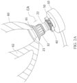
- FIGs 2A and 2B an embodiment of the present inflow cannula assembly CA for connecting a ventricular assist device (VAD) 10 to a heart 60.
- This inflow cannula assembly includes a deformable polymeric cannula 20, a pair of male and female fasteners 31, 32, a VAD coupler 40, and a VAD inlet adapter 50.
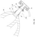
- FIG. 2A schematically shows how an inflow cannula 20 of a rotary pump is connected to left ventricle, whereas a sectional view illustrating the flow passage and the interconnected cannula assembly components with respect to a centrifugal type VAD is provided in FIG. 2B .
- the distal orifice defined as the farther cannula end viewed from the connected VAD 10, is configured in a bellmouth 21 (the first end of the cannula 20) extension of the cannula 20 with gradually increasing cone diameter.
- the cone angle of this bellmouth 21 is typically 30-75 deg relative to the axis of revolution of the conduit 22.
- the central portion of the cannula 20 is the conduit 22 with an axi-symmetric cross sectional distribution.
- This said funnel-shaped cannula 20 constitutes a geometric locking mechanism when inserted across a cored through-hole 61 in the ventricular wall of the heart 60.
- the original diameter of the through-hole 61 is generally in the range of 10-15 mm, which is substantially smaller than the outer diameter of the inserted conduit 22.
- Deformability of the present cannula invention hence, is essential, which allows the cannula 20 be crimped into a smaller prepacked delivery form to facilitate insertion.
- the squeezed cannula 20 will restore to its original form having its conduit be snuggly embraced with oversize to the cored myocardial through-hole 61.
- the bellmouth 21, as freed from crimping constraints will self-expand and hence constitute an anti-dislodging anchorage against the contacted endocardium, as shown in FIG. 2B .
- the cored hole size (10-15 mm in diameter) required for the present cannula 20 implantation can be substantially smaller when compared to that of a rigid-walled inflow conduit (20-30 mm in diameter) pertaining to the contemporary rotary pumps.
- Excising lesser amount of tissue mass from the cardiac wall is surgically and anatomically advantageous. It not only reduces a permanent loss of contractile muscle, but also mitigates the risk of injury to papillary muscle and chordae tendineae that is responsible for atrioventricular valvular opening and closing as well as the associated valve flow regurgitation if the valve is not fully closed during systole.
- aortic and mitral valves situated in the left ventricle for regulating one-way flow into and out of the ventricular chamber.
- mitral valve regurgitation may impair VAD support efficacy and promote intraventricular thrombus formation.
- mitral valve regurgitation would lead to pulmonary congestion and hypertension, potentially causing pulmonary edema and death-threatening right heart failure.
- rotary pump thrombosis complication was effectively annihilated using pump speed modulation strategy. As pump speed is lowered to allow intermittent valve opening and closing, a functional valve opening/closing is important.
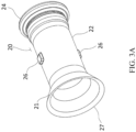
- FIGs. 3A , 3B , and FIG. 4A Two embodiments of such funnel-shaped cannula 20 are shown in FIGs. 3A , 3B , and FIG. 4A , respectively.
- polymeric elastomer such as silicone or polyurethane can be adopted as the material, which can be mold casted or injected into a seamless cannula with smooth blood-contacting surface.
- a sharp-edged tip 27 At the distal end of the bellmouth 21 is a sharp-edged tip 27 that can be attached to the endocardium with minimal geometric discontinuity.
- the rigidity of the bellmouth 21 reduces in proportion to the wall thickness toward the tip 27, rendering the bellmouth 21 flexible and shape-conformal when compressed against the endocardium.
- an overlay portion 28 of the conduit 22 in contact with the cored myocardium can be roughened to promote tissue ingrowth during the wound healing period.
- the surface of the overlay portion 28 can be made by attaching a felt with appropriate porosity or by depositing a thin layer of polymeric filaments generated, for example, by electrospinning. This rough overlay portion 28 can help immobilize or seal the implanted cannula 20 via tissue ingrowth and hence maintain a long-term hemostasis effectiveness postoperatively.
- FIG. 4A Another embodiment is to have the previous embodiment ( FIGs. 3A and 3B ) embedded with a stent 70 or a stent reinforcement, as shown in FIG. 4A .
- the stent 70 is flexible, and has a metallic material, such as super-elastic Nitinol material.
- the wall thickness can be further thinned to decrease the outer diameters of the cannula 20 (including the bellmouth 21 and the conduit 22).
- the implantability of the stent-embedded cannula would be upgraded without compromising the hemodynamic performance which is dominated by the inner diameter 25 of the conduit 22.
- the stent 70 may share a substantial amount of the pulsatile pressure loading exerted on the conduit 22, hence enhancing the conduit durability and safety. Mechanically, the stent 70 is able to endure large deformation without structural yielding that meets the foldability requirement of the present cannula 20.
- FIG. 4B and FIG. 4C A lateral and perspective view of a representative Nitinol stent insert is illustrated in FIG. 4B and FIG. 4C , respectively.
- the stent 70 has a zig-zag ring structure, and includes a plurality of arrays of zig-zag rings 71, 73 and connection members 72.
- the arrays of zig-zag rings 71, 73 are responsible for resisting the radial load, whereas the connection member 72 clusters the arrays of rings 71, 73 to resist the axial stretching force.
- the arrays of zig-zag rings 71 have tubular shape and are embedded in the wall of the conduit 22, whereas the arrays of rings 73 having cone-shaped structure are embedded in the wall of the bellmouth 21.
- the radial strength is gradually weakened along with the increase of the cone diameter toward the distal tip 27. Notice that when bellmouth 21 is locked with female fastener 32, insufficient radial strength in bellmouth 21 may lead to structural buckling and loss of shape-conformality, resulting in massive bleeding in use.
- the stent 70 can improve this polymeric material strength by providing sufficient anti-buckling capability without a need to increase the wall thickness of the bellmouth 21.
- an array of interconnected zig-zag ring structure 71, 73 is first cut out from a thin-walled, straight Nitinol tube using a laser cutter.
- This tubular zig-zag array structure is shown in FIG. 4D in an expanded planar view.
- the tubular array assembly 71, 73 can be step-by-step shaped into the stent 70 having a bellmouth intake.
- Surface grinding and electronic polishing are subsequently applied to remove the oxidized outer layer formed on the heat-treated surface of the stent 70.
- the final product is accomplished by mold co-injection of stent 70 with silicone or polyurethane elastomers, as illustrated in FIG. 4A .
- the present invention innovates a sutureless fixation approach.
- Conventional suture fixation relies on the tension force generated in the string by pulling tight the anchored suture pair.
- the present sutureless pump attachment adopts a completely different fixation and force generation mechanism provided by a fastener pair 31, 32.
- This new attachment design simultaneously locks and seals the inflow cannula 20 with respect to the connection site myocardium.
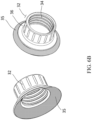
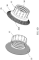
- Sutureless fixation of cannula 20 to the contacted myocardium is accomplished by a pair of male and female fasteners 31, 32, which are shown in FIGs. 5A , 5B and FIGs. 6A to 6D , respectively.
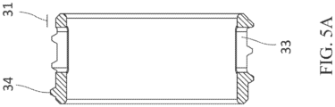
- FIGs. 5A and 5B Depicted in FIGs. 5A and 5B are the sectional and perspective views of the male fastener 31.
- a screw thread 34 is carved on the external surface of the male fastener 31, from end to end, with multiple slots 33 made approximately in the middle region of the male fastener 31.
- the inner diameter of the male fastener 31 is substantially equal, with a small clearance, to the outer diameter 29 of the cannula conduit 22.
- the female fastener 32 is a lock nut having a funnel-shaped distal cap 36 to be compressed against epicardium for locking and seal purposes.
- the angle of the cap 36 is approximately equal to the angle of the bellmouth 21.
- the cone of bellmouth 21 will deform slightly, in compliance with the fitted endocardium terrain, to simultaneously achieve the functions of seal (bleeding prevention) and cannula fixation.
- a cone cuff 35 made of surgical felt, is attached.
- the soft-contact porous feature provided by the felt is another guarantee of hemostasis. Tissues or cells may be ingrown into the void space in the cone cuff 35 along with the postoperative wound healing process. A few stay sutures can be placed around the cuff rim to further help fix the screwed female fastener 32 with the epicardium during the acute healing period.
- the present sutureless flow cannula implantation may encounter postoperative tissue atrophy at the clamped connection site. Such tissue atrophy will jeopardize the seal effectiveness and potentially causes bleeding at the connection site.
- FIGs 6C and 6D are shown another embodiment of the female fastener 32 intended to mitigate this atrophy-induced postoperative bleeding.
- the cuff 35 is additionally supported by a cone-shaped Nitinol stent 35N similar to that of the bellmouth stent 73 illustrated in FIGs. 4B and 4C .
- the deformed super-elastic Nitinol stent 35N will provide a contact spring load to assure that the cuff 35 always adheres to the epicardium during the wound healing process, hence obviating the risk of postoperative atrophy-induced blood leak.
- FIG. 7 shows the integrated fasteners 31, 32 as mounted on the cannula 20.
- Forces and strain involved in cannula deformation confers a special design feature of the present invention.
- Material elasticity consideration in fact, need to be carefully incorporated in the present design.
- the deformability ability of the cannula 20 is required as a prerequisite.
- the proximal or second end 24 (the flange ramp) of the cannula 20 ought to be crimped into a smaller profile so as to pass the end 24 through the ring-shaped fasteners 31, 32 sequentially.
- the male fastener 31 is first mounted and, along with the release of the crimped profile, locked onto the cannula conduit 22 via an engagement of those slots 33 in the fastener wall with the multiple protruded seats 26 on the conduit 22.
- the female fastener 32 is inserted following the same crimping and release of the cannula proximal end 24 and then screwed onto the male fastener 31.
- the bellmouth 21 and the cap 36 of the female fastener 32 will clamp the sandwiched myocardium from both sides across the insertion hole 61 to satisfy the fixation and leak-free requirements. It is worth noticing that the bellmouth 21 is shape-conformal to endocardium when compressed.
- the semi-rigid bellmouth 21 can be adaptively fit with the endocardial terrain, forming a seal barrier to obviate blood leakage concern.
- the male fastener 31 of the fastener pair which is anchored on the protruded seats 26 of the conduit 22, however, works as a support base to counteract the locking force generated.
- the present sutureless attachment possesses an intrinsic positive feedback mechanism built for bleeding control. As ventricle contracts and ventricular pressure increases, the compression force acting on the bellmouth 21 will increase accordingly and better seal off the attached flow cannula 20. The concern of bleeding at hypertension is hence literally ruled out.
- This positive feedback effect is lacking in the conventional fixation by means of suturing as illustrated in FIGs 1A to 1C .
- surgeon must check bleeding, based on a drug-induced temporary hypertension, after the completion of anastomotic suture attachment of the flow cannula 20.
- FIG. 2B is illustrated a sectional view of how the present invention is in lock position with a connected ventricular wall.
- Compression type locking mechanism enables a distributed force be exerted around the clamped myocardial area in contact.
- the soft contact nature over bellmouth 21 and female fastener cap 36 avoids the traditional problem of suture string cutting generated within the stitched myocardium, which, often leads to bleeding through enlarged suture fissure at hypertension.
- Cardiac muscle is particularly vulnerable to string cutting associated with conventional suturing anastomosis, a problem that is much dependent on the mastery of suturing skills possessed by the surgeon.
- the blood-contacting inner surface is configured to have a smooth geometric transition to the inlet of the connected VAD 10.
- the VAD inlet adapter 50 is a body of revolution comprising a wedge-shaped beak 51, a beak flange 53 and a base 54, forming an extension of a VAD inlet housing.
- the beak 51, or the foremost part of the inlet adapter 50 of a connected blood pump or VAD has an inner diameter 52 slightly larger than the inner diameter 25 of the flow cannula 20. Referring to FIG.
- the interface surface of the flange ramp 23 is sloped with an inclination angle 29 to the stream direction.
- Such ramp interface design keeps step or gap from being generated at interface surface of the flange ramp 23 due to limited manufacturing precision or matching concentricity associated with conventional butt connection. Nevertheless, this cone-shaped flange ramp 23 has an intrinsic shortcoming in fulfilling a concentric centerline alignment of the joined counterparts. This problem is solved by a special coupler design, as described below.
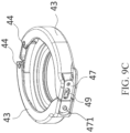
- the coupler 40 shown in FIGs. 9A to 9C , is specially designed in attempt to satisfy the hemodynamic and thromboresistance requirements when connecting the proximal cannula end 24 to the VAD inlet adapter 50. Illustrated in FIG. 9A are the components of the coupler 40 that constitutes the integration function.
- the coupler 40 includes a flange base 42, a pair of collars 43, and hinges 44 that join together the collars 43 with the flange base 42.
- Spring coils 45 are loaded in the hinge joint 46, maintaining the collars 43 in an opening position when unlocked ( FIG. 9B ).
- the collars 43 are grooved internally as shown in FIGs. 9A , 9B .
- the collars 43 have an internal grooved slot 431 to receive and compress sandwiched the flange base 42, the flange ramp 23 of the cannula 20, and the beak flange of the inlet adapter
- a leaf spring type latch 47 is installed at the tip of one collar 43 by welding a slab 471 on top of the latch 47 to attain the required spring force.
- the latch 47 will be bent as it slides on a ramp 49 on the opposing collar in the course of locking. As latch 47 clears the top of the ramp 49, it will drop down to the base of said ramp 49 by an elastic restoring force, thereby working as a safe for preventing incidental latch unlock or collar opening ascribed to pump vibration or rocking in long-term use.
- the latch 47 can be bent and lifted upward by a tool, permitting an unlocking force to be exerted to rotationally open the collars 43 and hence disengage the VAD 10 from the cannula 20.
- coupler 40 For the design of coupler 40 that is able to connect a rigid beak 51 with the semi-rigid cannula flange ramp 23 concentrically, a simultaneous catching around the entire peripheral rim of flange base 42 is critical. Whenever simultaneous catching/locking engagement fails to be accomplished, the initially caught cannula flange ramp 23 will be strained more than the other free portion, creating a tendency to tilt or disposition the unevenly contacted ramp surface 23 leading to an eccentric pump connection. Such an eccentric connection often is the causal factor that generates step or gap at the interface that leads to thrombus formation. This drawback is remedied by having the collar contour 41 of the distal flange of the coupler 40 configured in such a way that the locking engagement simultaneously includes all circumferential contact areas.
- the edge of the metallic beak 51 When locked, the edge of the metallic beak 51 will sink slightly into the compressed silicone ramp 23 with controlled depth and further reduces the interface discontinuity when exposed to blood stream.
- the conventional interface thrombus can be substantially minimized or annihilated by administrating a moderate anticoagulant regimen.
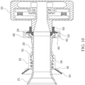
- FIG. 10 illustrates an integrated relationship between the joined inflow cannula 20 and the inlet adapter 50 of the VAD 10, locked together by the coupler 40.
- the present interface connection between pump and cannula has two hemodynamic merits for reducing thrombus formation in-situ. First, there will be literally no obvious step or gap type joint discontinuities generated as observed in the conventional butt connection. Second, stasis flow located in the interface of the beak leading-edge 56 can be minimized.
- connection interface will be maintained with high-speed, substantially improving the butt connection drawback, namely the forward- or backward-facing step existing at the interface, that generates flow stasis and promotes thrombotic adverse events in-situ and in the blood stream.
- Implantation of the present inflow cannula invention 20 and connection of said cannula 20 to rotary blood pump 10 are summarized below.
- the step-by-step procedural instructions that enable such implantation are described as follows:
- an embodiment of the present disclosure provides an inflow cannula assembly, for transporting blood between a heart chamber and a ventricular assist device (VAD), which includes a deformable polymeric cannula, a pair of male and female fasteners, a VAD coupler, a VAD inlet adapter, and a VAD inlet adapter.
- the cannula includes: a first end, with a bellmouth intake to be inserted into heart chamber; a second end, with a flange ramp; and a conduit, wherein the first and second ends are integrally joined by the conduit, and the entire inner surface of the cannula is smooth and seamless.
- the male and female fasteners are screw interconnected with the male fastener anchored on the cannula.
- the second end is configured to interface with the VAD inlet adapter.
- the VAD coupler connects the second end with the VAD inlet adapter, and the VAD coupler includes a flange base and a pair of collars pinned on the flange base, wherein the collars have an internal grooved slots to receive and compress the sandwiched flange base, the flange ramp of the cannula, and a beak flange of the VAD inlet adapter; and the VAD inlet adapter includes a wedge-shaped beak to be interfaced with the cannula's second end, the beak flange to be accepted by the coupler, and a base integrated with the VAD.
Landscapes
- Health & Medical Sciences (AREA)
- Engineering & Computer Science (AREA)
- Heart & Thoracic Surgery (AREA)
- Cardiology (AREA)
- Biomedical Technology (AREA)
- General Health & Medical Sciences (AREA)
- Veterinary Medicine (AREA)
- Hematology (AREA)
- Life Sciences & Earth Sciences (AREA)
- Animal Behavior & Ethology (AREA)
- Mechanical Engineering (AREA)
- Public Health (AREA)
- Anesthesiology (AREA)
- Medical Informatics (AREA)
- Physics & Mathematics (AREA)
- Optics & Photonics (AREA)
- Vascular Medicine (AREA)
- Human Computer Interaction (AREA)
- External Artificial Organs (AREA)
- Surgical Instruments (AREA)
- Prostheses (AREA)
Claims (11)
- Zuflusskanülenanordnung (CA) zum Transportieren von Blut zwischen einer Herzkammer und einer ventrikulären Hilfsvorrichtung (VAD) (10), umfassend:eine verformbare Polymerkanüle (20), umfassend:ein erstes Ende, das als Einlass verwendet wird, um in die Herzkammer eingeführt zu werden, und so geformt ist, dass es einen Glockenmund (21) aufweist;ein zweites Ende, das so geformt ist, dass es eine Flanschschräge (23) aufweist; undeine Leitung (22), wobei das erste Ende und das zweite Ende einstückig durch die Leitung (22) zusammengefügt sind und eine gesamte Innenfläche der Kanüle (22) glatt und nahtlos ist;ein männliches Befestigungselement (31) und ein weibliches Befestigungselement (32), wobei das männliche Befestigungselement (31) und das weibliche Befestigungselement (32) mit dem an der Kanüle (22) verankerten männlichen Befestigungselement (31) schraubverbunden sind;dadurch gekennzeichnet, dass die Zuflusskanülenanordnung (CA) ferner umfasst:einen ventrikuläre-Hilfsvorrichtung(VAD)-Koppler (40); undeinen ventrikuläre-Hilfsvorrichtung(VAD)-Zulaufadapter (50), der so konfiguriert ist, dass er mit der VAD (10) ankoppelt, wobei:das zweite Ende so konfiguriert ist, dass es über den VAD-Zulaufadapter (50) mit der VAD (10) ankoppelt;der VAD-Koppler das zweite Ende mit dem VAD-Zulaufadapter verbindet und der VAD-Koppler (40) eine Sandwich-Flanschbasis (42) und ein Paar Kragen (43) enthält, die auf die Sandwich-Flanschbasis (42) aufgesteckt sind, wobei die Kragen (43) mindestens einen inneren gerillten Schlitz (431) aufweisen, um die Sandwich-Flanschbasis (42), die Flanschschräge (23) der Kanüle (20) und einen Schnabelflansch (53) des VAD-Zulaufadapters (50) aufzunehmen und zusammenzudrücken; undder VAD-Zulaufadapter (50) einen keilförmigen Schnabel (51), um mit dem zweiten Ende angekoppelt zu werden, den Schnabelflansch (53), der von dem VAD-Koppler (40) aufgenommen werden soll, und eine mit der VAD (10) integrierte Basis (54) enthält.
- Zuflusskanülenanordnung gemäß Anspruch 1, wobei der Glockenmund (21) zu seiner Spitze (27) hin eine allmählich abnehmende Wandstärke aufweist und die Spitze (27) buchstäblich scharfkantig ist.
- Zuflusskanülenanordnung gemäß Anspruch 1, wobei ein Überlagerungsabschnitt (28) der Leitung (22), der mit einem Myokard der Herzkammer in Kontakt steht, aufgeraut ist, um das Einwachsen von Zellen und Gewebe zu Hämostase- und Immobilisierungszwecken zu fördern.
- Zuflusskanülenanordnung gemäß Anspruch 1, wobei das weibliche Befestigungselement (32) eine Kappe (36) in Kontakt mit einem Epikard der Herzkammer enthält und die Kappe (36) mit einem porösen Material beschichtet ist, um das Einwachsen von Zellen und Gewebe zu Hämostase- und Immobilisierungszwecken zu fördern.
- Zuflusskanülenanordnung gemäß Anspruch 4, wobei die Kappe (36) von einem Nitinol-Stent getragen wird, um eine Federkraft zu erzeugen, wenn sie auf dem Epikard verriegelt ist, so dass die Kappe (36) immer auf dem Epikard angebracht ist.
- Zuflusskanülenanordnung gemäß Anspruch 1, wobei der Schnabel (51) des VAD-Zulaufadapter (50) und das zweite Ende über die Flanschschräge (23) angekoppelt sind, wobei ein Innendurchmesser des Schnabels (51) etwas größer ist als ein Innendurchmesser der Leitung (22), wobei eine Schnittstellenfläche der Flanschschräge (23) im Allgemeinen um 30 bis 60 Grad zu einer Mittellinie der Kanüle (20) geneigt ist.
- Zuflusskanülenanordnung gemäß Anspruch 1, wobei der VAD-Koppler (40) eine Entkopplungssperre (47) und eine Kragenkontur (41) aufweist, die gleichzeitig an einem gesamten Umfangsrand der Sandwich-Flanschbasis (42) einrastet, um eine konzentrische Kupplung zwischen dem zweiten Ende und dem VAD-Zulaufadapter (51) der angeschlossenen VAD (10) zu gewährleisten.
- Zuflusskanülenanordnung gemäß Anspruch 1 ferner umfassend einen Stent (70), der in eine Wand der Kanüle (20) eingebettet ist.
- Zuflusskanülenanordnung gemäß Anspruch 8, wobei der Stent (70) aus Nitinol-Material hergestellt ist.
- Zuflusskanülenanordnung gemäß Anspruch 8, wobei der Stent eine Zick-Zack-Ring-Anordnungsstruktur aufweist, die aus einer Vielzahl von Zick-Zack-Ringen besteht.
- Zuflusskanülenanordnung gemäß Anspruch 10, wobei die Zick-Zack-Ring-Anordnungsstruktur aus einem rohrförmigen Teil, der in der Leitung (22) angeordnet ist, und einem kegelförmigen Teil, der in dem Glockenmund (21) angeordnet ist, besteht.
Applications Claiming Priority (3)
| Application Number | Priority Date | Filing Date | Title |
|---|---|---|---|
| US202163162086P | 2021-03-17 | 2021-03-17 | |
| US202163162098P | 2021-03-17 | 2021-03-17 | |
| PCT/US2022/020414 WO2022197725A1 (en) | 2021-03-17 | 2022-03-15 | Sutureless inflow cannula assembly for connecting ventricular assist devices to human circulation |
Publications (4)
| Publication Number | Publication Date |
|---|---|
| EP4093482A1 EP4093482A1 (de) | 2022-11-30 |
| EP4093482A4 EP4093482A4 (de) | 2024-02-28 |
| EP4093482C0 EP4093482C0 (de) | 2025-04-23 |
| EP4093482B1 true EP4093482B1 (de) | 2025-04-23 |
Family
ID=83285516
Family Applications (3)
| Application Number | Title | Priority Date | Filing Date |
|---|---|---|---|
| EP22772072.9A Active EP4251257B1 (de) | 2021-03-17 | 2022-03-15 | Paraaortische blutpumpenvorrichtung |
| EP22754757.7A Active EP4093482B1 (de) | 2021-03-17 | 2022-03-15 | Nahtlose zuflusskanülenanordnung zum verbinden von ventrikelunterstützungsvorrichtungen mit einem menschlichen kreislauf |
| EP22754756.9A Active EP4093483B1 (de) | 2021-03-17 | 2022-03-15 | Implantierbares co-pulsatiles epiventrikuläres kreislaufunterstützungssystem mit nahtloser strömungskanülenanordnung |
Family Applications Before (1)
| Application Number | Title | Priority Date | Filing Date |
|---|---|---|---|
| EP22772072.9A Active EP4251257B1 (de) | 2021-03-17 | 2022-03-15 | Paraaortische blutpumpenvorrichtung |
Family Applications After (1)
| Application Number | Title | Priority Date | Filing Date |
|---|---|---|---|
| EP22754756.9A Active EP4093483B1 (de) | 2021-03-17 | 2022-03-15 | Implantierbares co-pulsatiles epiventrikuläres kreislaufunterstützungssystem mit nahtloser strömungskanülenanordnung |
Country Status (11)
| Country | Link |
|---|---|
| US (6) | US20220296877A1 (de) |
| EP (3) | EP4251257B1 (de) |
| JP (3) | JP7527695B2 (de) |
| KR (3) | KR102937655B1 (de) |
| CN (2) | CN121288187A (de) |
| AU (2) | AU2022239445B2 (de) |
| BR (2) | BR112023013587A2 (de) |
| GB (3) | GB2616240B (de) |
| IL (2) | IL300331A (de) |
| TW (6) | TWI860047B (de) |
| WO (5) | WO2022197725A1 (de) |
Families Citing this family (15)
| Publication number | Priority date | Publication date | Assignee | Title |
|---|---|---|---|---|
| DE60230633D1 (de) | 2002-11-08 | 2009-02-12 | Procter & Gamble | Absorbierender Wegwerfartikel mit schmutzverdeckender Deckschicht |
| WO2020039592A1 (ja) * | 2018-08-24 | 2020-02-27 | 株式会社サンメディカル技術研究所 | 管路形成ユニット及び管継手 |
| TR201923195A2 (tr) * | 2019-12-31 | 2021-07-26 | Ahmet Elibol | Ventri̇küler destek ci̇hazlarinin vakum destekli̇ di̇ki̇şsi̇z gi̇ri̇ş kanül i̇mplantasyonu |
| US12290675B2 (en) * | 2021-04-22 | 2025-05-06 | Board Of Regents, The University Of Texas System | Method and apparatus for assisting a heart |
| JP7714254B2 (ja) * | 2022-03-15 | 2025-07-29 | スリーアール ライフ サイエンシズ コーポレーション | 漏れのない大動脈アダプターアセンブリを有する血液ポンプ装置 |
| US11745004B1 (en) * | 2022-07-15 | 2023-09-05 | Vitalmex Internacional S.A. De C.V. | Ventricular assist devices and methods |
| KR102851788B1 (ko) * | 2022-10-28 | 2025-08-29 | 강원대학교산학협력단 | 체외막 산소 공급 장치용 역박동 제어 방법, 기록매체 및 체외막 산소 공급 장치 |
| CN115807766A (zh) * | 2022-12-15 | 2023-03-17 | 上海心恒睿医疗科技有限公司 | 柱塞泵零位标定方法、血泵灌注清洗设备及血泵系统 |
| CN116271501B (zh) * | 2023-04-26 | 2024-06-11 | 心擎医疗(苏州)股份有限公司 | 导管泵 |
| CN116889679B (zh) * | 2023-06-08 | 2024-07-19 | 上海心恒睿医疗科技有限公司 | 心室辅助系统 |
| WO2025042270A1 (en) * | 2023-08-24 | 2025-02-27 | Pulsecath B.V. | Blood pump system, and blood pump driver |
| WO2025041110A1 (en) * | 2023-08-24 | 2025-02-27 | Cardiacbooster B.V. | Docking station for circulatory assist devices |
| WO2025188554A1 (en) * | 2024-03-07 | 2025-09-12 | Corisma Cardiovascular | Devices and methods for supporting cardiac function |
| CN118022165B (zh) * | 2024-03-28 | 2024-09-17 | 深圳市万至达电机制造有限公司 | 一种介入式轴流血泵 |
| WO2026093146A1 (en) * | 2024-10-31 | 2026-05-07 | Abiomed Europe Gmbh | Blood pump |
Family Cites Families (61)
| Publication number | Priority date | Publication date | Assignee | Title |
|---|---|---|---|---|
| FR1514319A (fr) * | 1967-01-11 | 1968-02-23 | Dispositif pour l'implantation dans la région apicale du coeur d'un ventricule artificiel | |
| US4240409A (en) * | 1979-02-21 | 1980-12-23 | Thermo Electron Corporation | Apparatus for assisting circulation of blood |
| JPH03242143A (ja) * | 1990-02-19 | 1991-10-29 | Aisin Seiki Co Ltd | 人工心臓装置の接続構造ならびに人工弁リングの製造方法 |
| US5332403A (en) * | 1992-08-17 | 1994-07-26 | Jack Kolff | LVAD with t-shape and unidirectional valve |
| US6371982B2 (en) * | 1997-10-09 | 2002-04-16 | St. Jude Medical Cardiovascular Group, Inc. | Graft structures with compliance gradients |
| US6146325A (en) * | 1999-06-03 | 2000-11-14 | Arrow International, Inc. | Ventricular assist device |
| US6942672B2 (en) | 2001-10-23 | 2005-09-13 | Vascor, Inc. | Method and apparatus for attaching a conduit to the heart or a blood vessel |
| US7258679B2 (en) * | 2002-08-09 | 2007-08-21 | Vascor, Inc. | Inflow conduit for ventricular assist device |
| AU2003901345A0 (en) * | 2003-03-21 | 2003-04-03 | Ventracor Limited | Improved cannula |
| US7217236B2 (en) * | 2003-05-30 | 2007-05-15 | Innovamedica S.A. De C.V. | Universal pneumatic ventricular assist device |
| AU2003903726A0 (en) * | 2003-07-18 | 2003-07-31 | Ventracor Limited | A device for detecting heart pumping state |
| US7066874B2 (en) * | 2004-01-06 | 2006-06-27 | Bay Innovation Group, Llc | Devices and methods for blood flow assistance |
| US20060036313A1 (en) | 2004-08-11 | 2006-02-16 | Vassiliades Thomas A | Apicoaortic conduit connector and method for using |
| US9138228B2 (en) | 2004-08-11 | 2015-09-22 | Emory University | Vascular conduit device and system for implanting |
| CA2611313A1 (en) * | 2005-06-06 | 2006-12-14 | The Cleveland Clinic Foundation | Blood pump |
| ITMI20051420A1 (it) * | 2005-07-22 | 2007-01-23 | A N B Technology S R L | Dispositivo di assistenza cardiocircolatoria |
| US8702777B2 (en) * | 2005-08-22 | 2014-04-22 | Incept, Llc | Steep-taper flared stents and apparatus and methods for delivering them |
| US8343028B2 (en) * | 2005-10-19 | 2013-01-01 | Thoratec Corporation | Ventricular pump coupling |
| CN101472627B (zh) * | 2006-01-30 | 2013-05-08 | 国立成功大学 | 双元脉动双心室辅助装置 |
| JP2009530041A (ja) * | 2006-03-23 | 2009-08-27 | ザ・ペン・ステート・リサーチ・ファンデーション | 拡張可能なインペラポンプを有する心臓補助装置 |
| US7846123B2 (en) | 2007-04-24 | 2010-12-07 | Emory University | Conduit device and system for implanting a conduit device in a tissue wall |
| GB0718943D0 (en) * | 2007-09-28 | 2007-11-07 | Univ Nottingham | Mechanical support |
| US8562507B2 (en) | 2009-02-27 | 2013-10-22 | Thoratec Corporation | Prevention of aortic valve fusion |
| AU2010266166B2 (en) * | 2009-07-01 | 2015-09-03 | The Penn State Research Foundation | Blood pump with expandable cannula |
| US9682180B2 (en) * | 2009-11-15 | 2017-06-20 | Thoratec Corporation | Attachment system, device and method |
| TW201217010A (en) | 2010-06-22 | 2012-05-01 | Thoratec Corp | Apparatus and method for modifying pressure-flow characteristics of a pump |
| WO2012018917A1 (en) * | 2010-08-03 | 2012-02-09 | World Heart Corporation | Conformal cannula device and related methods |
| US20120138533A1 (en) * | 2010-12-01 | 2012-06-07 | Curtis James R | Dialysis system control system with user interface |
| PL217321B1 (pl) * | 2011-02-28 | 2014-07-31 | Fundacja Rozwoju Kardiochirurgii Im Prof Zbigniewa Religi | Pompa krwi, zwłaszcza pneumatyczna komora wspomagania serca |
| US10226558B2 (en) * | 2011-05-13 | 2019-03-12 | Mayo Foundation For Medical Education And Research | Cannula apparatus and ventricular assist systems using the cannula apparatus |
| US8827887B2 (en) * | 2011-05-18 | 2014-09-09 | Thoratec Corporation | Assembly and method of implanting a heart assist system |
| US8579790B2 (en) * | 2012-01-05 | 2013-11-12 | Thoratec Corporation | Apical ring for ventricular assist device |
| US9199019B2 (en) | 2012-08-31 | 2015-12-01 | Thoratec Corporation | Ventricular cuff |
| AU2012390067B2 (en) * | 2012-09-21 | 2017-11-02 | Reinheart Gmbh | Method of controlling the speed of an ventricular assist device (VAD) and ventricular assist device. |
| US9364596B2 (en) | 2013-01-04 | 2016-06-14 | HeartWave, Inc. | Controller and power source for implantable blood pump |
| CN105246522B (zh) * | 2013-03-15 | 2017-10-20 | 华思科公司 | 胸主动脉心室辅助系统 |
| DE102013208038B4 (de) * | 2013-05-02 | 2016-09-08 | Michael Siegenthaler | Katheterbasierendes Herzunterstützungssystem |
| CN106029125B (zh) * | 2014-02-26 | 2019-11-19 | 特克法马许可公司 | 用于给送流体产品的装置 |
| US10485909B2 (en) * | 2014-10-31 | 2019-11-26 | Thoratec Corporation | Apical connectors and instruments for use in a heart wall |
| WO2016150474A1 (en) * | 2015-03-20 | 2016-09-29 | Université D'aix-Marseille | Blood flow reducer and method using the same |
| WO2017004175A1 (en) * | 2015-06-29 | 2017-01-05 | Thoratec Corporation | Ventricular assist devices having a hollow rotor and methods of use |
| EP3135326A1 (de) * | 2015-08-24 | 2017-03-01 | Berlin Heart GmbH | Herzpumpe sowie verfahren zum betrieb einer herzpumpe |
| AU2017205172B2 (en) | 2016-01-06 | 2022-02-10 | Bivacor Inc. | Heart pump |
| CN109475671B (zh) * | 2016-07-19 | 2021-08-03 | 心脏器械股份有限公司 | 心室辅助设备及其集成传感器 |
| US10894116B2 (en) * | 2016-08-22 | 2021-01-19 | Tc1 Llc | Heart pump cuff |
| ES2754405T3 (es) * | 2016-08-23 | 2020-04-17 | Abiomed Europe Gmbh | Dispositivo de asistencia ventricular |
| EP3528864B1 (de) * | 2016-10-20 | 2020-12-30 | Heartware, Inc. | Einströmkanüle |
| FR3059907B1 (fr) * | 2016-12-09 | 2019-05-24 | Fineheart | Dispositif d'ancrage sans suture d'une pompe cardiaque |
| WO2018183568A1 (en) * | 2017-03-29 | 2018-10-04 | Tc1 Llc | Pressure sensing ventricular assist devices and methods of use |
| EP4039321B1 (de) * | 2018-01-10 | 2026-03-25 | Magenta Medical Ltd. | Ventrikelunterstützungsvorrichtung |
| EP3536955A1 (de) | 2018-03-08 | 2019-09-11 | Berlin Heart GmbH | Antriebsvorrichtung für eine membranfluidpumpe und betriebsverfahren |
| US11517740B2 (en) * | 2018-03-15 | 2022-12-06 | Tc1 Llc | Methods for controlling a left ventricular assist device |
| US11141580B2 (en) * | 2018-05-15 | 2021-10-12 | Cardiovascular Systems, Inc. | Intravascular blood pump system with integrated conductor(s) in housing and methods thereof |
| FR3081333B1 (fr) | 2018-05-22 | 2020-06-05 | Fineheart | Dispositif d'ancrage d'une pompe cardiaque |
| EP3610902A1 (de) * | 2018-08-17 | 2020-02-19 | Berlin Heart GmbH | Pumpensystem zum pumpen eines fluids und verfahren zum betrieb des pumpensystems |
| CN109395185A (zh) * | 2018-11-15 | 2019-03-01 | 安徽通灵仿生科技有限公司 | 一种辅助左心室功能的搏动式导管装置 |
| WO2020160526A2 (en) * | 2019-02-01 | 2020-08-06 | Kardiatec SA | Pressure unloading left ventricular assist device and methods for assisting a human heart |
| JP7527300B2 (ja) | 2019-02-28 | 2024-08-02 | ティーシーワン エルエルシー | 拡張可能なスリーブを含む流入カニューレ、及びそれを植え込むための方法 |
| CN112006811B (zh) * | 2019-05-28 | 2024-02-06 | 上海创心医学科技有限公司 | 一种血管重建装置 |
| TR201923195A2 (tr) * | 2019-12-31 | 2021-07-26 | Ahmet Elibol | Ventri̇küler destek ci̇hazlarinin vakum destekli̇ di̇ki̇şsi̇z gi̇ri̇ş kanül i̇mplantasyonu |
| US11896814B2 (en) * | 2020-05-04 | 2024-02-13 | Heartware, Inc. | Toolless quick connect sewing ring |
-
2022
- 2022-03-15 WO PCT/US2022/020414 patent/WO2022197725A1/en not_active Ceased
- 2022-03-15 CN CN202511354179.5A patent/CN121288187A/zh active Pending
- 2022-03-15 GB GB2309839.5A patent/GB2616240B/en active Active
- 2022-03-15 AU AU2022239445A patent/AU2022239445B2/en active Active
- 2022-03-15 KR KR1020237021964A patent/KR102937655B1/ko active Active
- 2022-03-15 BR BR112023013587A patent/BR112023013587A2/pt unknown
- 2022-03-15 AU AU2022238306A patent/AU2022238306B2/en active Active
- 2022-03-15 EP EP22772072.9A patent/EP4251257B1/de active Active
- 2022-03-15 GB GB2212460.6A patent/GB2610487B/en active Active
- 2022-03-15 WO PCT/US2022/020403 patent/WO2022197716A1/en not_active Ceased
- 2022-03-15 BR BR112023013596A patent/BR112023013596A2/pt unknown
- 2022-03-15 EP EP22754757.7A patent/EP4093482B1/de active Active
- 2022-03-15 US US17/695,344 patent/US20220296877A1/en active Pending
- 2022-03-15 GB GB2212467.1A patent/GB2616929B/en active Active
- 2022-03-15 CN CN202280002629.2A patent/CN115666708A/zh active Pending
- 2022-03-15 US US17/695,376 patent/US12350484B2/en active Active
- 2022-03-15 KR KR1020237031562A patent/KR20230155467A/ko active Pending
- 2022-03-15 EP EP22754756.9A patent/EP4093483B1/de active Active
- 2022-03-15 IL IL300331A patent/IL300331A/en unknown
- 2022-03-15 JP JP2023541966A patent/JP7527695B2/ja active Active
- 2022-03-15 KR KR1020237021961A patent/KR102944362B1/ko active Active
- 2022-03-15 US US17/695,390 patent/US12233252B2/en active Active
- 2022-03-15 JP JP2023557126A patent/JP7623741B2/ja active Active
- 2022-03-15 JP JP2023541970A patent/JP7511956B2/ja active Active
- 2022-03-15 WO PCT/US2022/020409 patent/WO2022197721A1/en not_active Ceased
- 2022-03-15 IL IL300325A patent/IL300325B2/en unknown
- 2022-03-16 TW TW112131179A patent/TWI860047B/zh active
- 2022-03-16 TW TW111109722A patent/TWI826961B/zh active
- 2022-03-16 TW TW111109721A patent/TWI826960B/zh active
- 2022-03-16 TW TW111109720A patent/TWI826959B/zh active
- 2022-03-16 TW TW111109723A patent/TWI835092B/zh active
- 2022-03-16 TW TW111109719A patent/TWI835091B/zh active
- 2022-12-02 WO PCT/US2022/051705 patent/WO2023177429A1/en not_active Ceased
- 2022-12-02 US US18/074,201 patent/US20230264013A1/en active Pending
- 2022-12-02 WO PCT/US2022/051699 patent/WO2023177428A1/en not_active Ceased
- 2022-12-02 US US18/074,180 patent/US20230100925A1/en active Pending
-
2025
- 2025-04-01 US US19/097,496 patent/US20250229079A1/en active Pending
Also Published As
Similar Documents
| Publication | Publication Date | Title |
|---|---|---|
| AU2022239445B2 (en) | Sutureless inflow cannula assembly for connecting ventricular assist devices to human circulation | |
| US8187323B2 (en) | Valve to myocardium tension members device and method | |
| US20090157174A1 (en) | Systems and methods for enabling heart valve replacement | |
| CN110603007A (zh) | 用于经导管二尖瓣和三尖瓣修复的装置和方法 | |
| WO2020018385A1 (en) | Systems and methods for treating lumenal valves | |
| JP2011516209A (ja) | 心臓弁を修復するための弁形成リングおよび方法 | |
| CN104771247A (zh) | 一种治疗二尖瓣返流的装置及方法 | |
| AU2011300644A1 (en) | Valve replacement devices and a system comprising the valve replacement device and a delivery device therefor | |
| CN117100459A (zh) | 瓣膜支架及瓣膜假体 | |
| CN114948345B (zh) | 心脏瓣膜定位装置、心脏瓣膜置换组件及植入方法 | |
| CN215937813U (zh) | 一种心脏瓣膜假体 | |
| CN115697463B (zh) | 连接心室辅助装置到人体循环的无缝线入流导管组件 | |
| WO2021004462A1 (zh) | 一种人工心脏瓣叶及心脏瓣膜假体 | |
| CN120548154A (zh) | 用于将心脏瓣膜附接至心脏假体的系统以及设置有这种附接系统的心脏假体 | |
| CN219354276U (zh) | 瓣膜的修复装置及系统 | |
| CN104582637B (zh) | 用于经导管治疗瓣膜反流的装置、系统和方法 |
Legal Events
| Date | Code | Title | Description |
|---|---|---|---|
| STAA | Information on the status of an ep patent application or granted ep patent |
Free format text: STATUS: UNKNOWN |
|
| STAA | Information on the status of an ep patent application or granted ep patent |
Free format text: STATUS: THE INTERNATIONAL PUBLICATION HAS BEEN MADE |
|
| PUAI | Public reference made under article 153(3) epc to a published international application that has entered the european phase |
Free format text: ORIGINAL CODE: 0009012 |
|
| STAA | Information on the status of an ep patent application or granted ep patent |
Free format text: STATUS: REQUEST FOR EXAMINATION WAS MADE |
|
| 17P | Request for examination filed |
Effective date: 20220825 |
|
| AK | Designated contracting states |
Kind code of ref document: A1 Designated state(s): AL AT BE BG CH CY CZ DE DK EE ES FI FR GB GR HR HU IE IS IT LI LT LU LV MC MK MT NL NO PL PT RO RS SE SI SK SM TR |
|
| REG | Reference to a national code |
Ref country code: DE Ref legal event code: R079 Free format text: PREVIOUS MAIN CLASS: A61M0060863000 Ipc: A61M0060165000 Ref document number: 602022013663 Country of ref document: DE |
|
| A4 | Supplementary search report drawn up and despatched |
Effective date: 20240129 |
|
| RIC1 | Information provided on ipc code assigned before grant |
Ipc: A61M 60/88 20210101ALI20240123BHEP Ipc: A61M 60/878 20210101ALI20240123BHEP Ipc: A61M 60/865 20210101ALI20240123BHEP Ipc: A61M 60/863 20210101ALI20240123BHEP Ipc: A61M 60/859 20210101ALI20240123BHEP Ipc: A61M 60/857 20210101ALI20240123BHEP Ipc: A61M 60/837 20210101ALI20240123BHEP Ipc: A61M 60/835 20210101ALI20240123BHEP Ipc: A61M 60/531 20210101ALI20240123BHEP Ipc: A61M 60/515 20210101ALI20240123BHEP Ipc: A61M 60/427 20210101ALI20240123BHEP Ipc: A61M 60/274 20210101ALI20240123BHEP Ipc: A61M 60/165 20210101AFI20240123BHEP |
|
| DAV | Request for validation of the european patent (deleted) | ||
| DAX | Request for extension of the european patent (deleted) | ||
| REG | Reference to a national code |
Ref country code: DE Ref legal event code: R079 Free format text: PREVIOUS MAIN CLASS: A61M0060165000 Ipc: A61M0060178000 Ref country code: DE Ref legal event code: R079 Ref document number: 602022013663 Country of ref document: DE Free format text: PREVIOUS MAIN CLASS: A61M0060165000 Ipc: A61M0060178000 |
|
| GRAP | Despatch of communication of intention to grant a patent |
Free format text: ORIGINAL CODE: EPIDOSNIGR1 |
|
| STAA | Information on the status of an ep patent application or granted ep patent |
Free format text: STATUS: GRANT OF PATENT IS INTENDED |
|
| RIC1 | Information provided on ipc code assigned before grant |
Ipc: A61M 60/865 20210101ALI20241118BHEP Ipc: A61M 60/863 20210101ALI20241118BHEP Ipc: A61M 60/859 20210101ALI20241118BHEP Ipc: A61M 60/232 20210101ALI20241118BHEP Ipc: A61M 60/178 20210101AFI20241118BHEP |
|
| INTG | Intention to grant announced |
Effective date: 20241129 |
|
| GRAS | Grant fee paid |
Free format text: ORIGINAL CODE: EPIDOSNIGR3 |
|
| GRAA | (expected) grant |
Free format text: ORIGINAL CODE: 0009210 |
|
| STAA | Information on the status of an ep patent application or granted ep patent |
Free format text: STATUS: THE PATENT HAS BEEN GRANTED |
|
| AK | Designated contracting states |
Kind code of ref document: B1 Designated state(s): AL AT BE BG CH CY CZ DE DK EE ES FI FR GB GR HR HU IE IS IT LI LT LU LV MC MK MT NL NO PL PT RO RS SE SI SK SM TR |
|
| REG | Reference to a national code |
Ref country code: GB Ref legal event code: FG4D |
|
| REG | Reference to a national code |
Ref country code: CH Ref legal event code: EP |
|
| REG | Reference to a national code |
Ref country code: DE Ref legal event code: R096 Ref document number: 602022013663 Country of ref document: DE |
|
| REG | Reference to a national code |
Ref country code: IE Ref legal event code: FG4D |
|
| U01 | Request for unitary effect filed |
Effective date: 20250428 |
|
| U07 | Unitary effect registered |
Designated state(s): AT BE BG DE DK EE FI FR IT LT LU LV MT NL PT RO SE SI Effective date: 20250507 |
|
| PG25 | Lapsed in a contracting state [announced via postgrant information from national office to epo] |
Ref country code: ES Free format text: LAPSE BECAUSE OF FAILURE TO SUBMIT A TRANSLATION OF THE DESCRIPTION OR TO PAY THE FEE WITHIN THE PRESCRIBED TIME-LIMIT Effective date: 20250423 |
|
| PG25 | Lapsed in a contracting state [announced via postgrant information from national office to epo] |
Ref country code: NO Free format text: LAPSE BECAUSE OF FAILURE TO SUBMIT A TRANSLATION OF THE DESCRIPTION OR TO PAY THE FEE WITHIN THE PRESCRIBED TIME-LIMIT Effective date: 20250723 Ref country code: GR Free format text: LAPSE BECAUSE OF FAILURE TO SUBMIT A TRANSLATION OF THE DESCRIPTION OR TO PAY THE FEE WITHIN THE PRESCRIBED TIME-LIMIT Effective date: 20250724 |
|
| PG25 | Lapsed in a contracting state [announced via postgrant information from national office to epo] |
Ref country code: PL Free format text: LAPSE BECAUSE OF FAILURE TO SUBMIT A TRANSLATION OF THE DESCRIPTION OR TO PAY THE FEE WITHIN THE PRESCRIBED TIME-LIMIT Effective date: 20250423 |
|
| PG25 | Lapsed in a contracting state [announced via postgrant information from national office to epo] |
Ref country code: HR Free format text: LAPSE BECAUSE OF FAILURE TO SUBMIT A TRANSLATION OF THE DESCRIPTION OR TO PAY THE FEE WITHIN THE PRESCRIBED TIME-LIMIT Effective date: 20250423 |
|
| PG25 | Lapsed in a contracting state [announced via postgrant information from national office to epo] |
Ref country code: RS Free format text: LAPSE BECAUSE OF FAILURE TO SUBMIT A TRANSLATION OF THE DESCRIPTION OR TO PAY THE FEE WITHIN THE PRESCRIBED TIME-LIMIT Effective date: 20250723 |
|
| PG25 | Lapsed in a contracting state [announced via postgrant information from national office to epo] |
Ref country code: IS Free format text: LAPSE BECAUSE OF FAILURE TO SUBMIT A TRANSLATION OF THE DESCRIPTION OR TO PAY THE FEE WITHIN THE PRESCRIBED TIME-LIMIT Effective date: 20250823 |
|
| PG25 | Lapsed in a contracting state [announced via postgrant information from national office to epo] |
Ref country code: SM Free format text: LAPSE BECAUSE OF FAILURE TO SUBMIT A TRANSLATION OF THE DESCRIPTION OR TO PAY THE FEE WITHIN THE PRESCRIBED TIME-LIMIT Effective date: 20250423 |
|
| PG25 | Lapsed in a contracting state [announced via postgrant information from national office to epo] |
Ref country code: CZ Free format text: LAPSE BECAUSE OF FAILURE TO SUBMIT A TRANSLATION OF THE DESCRIPTION OR TO PAY THE FEE WITHIN THE PRESCRIBED TIME-LIMIT Effective date: 20250423 |
|
| PG25 | Lapsed in a contracting state [announced via postgrant information from national office to epo] |
Ref country code: SK Free format text: LAPSE BECAUSE OF FAILURE TO SUBMIT A TRANSLATION OF THE DESCRIPTION OR TO PAY THE FEE WITHIN THE PRESCRIBED TIME-LIMIT Effective date: 20250423 |
|
| PLBE | No opposition filed within time limit |
Free format text: ORIGINAL CODE: 0009261 |
|
| STAA | Information on the status of an ep patent application or granted ep patent |
Free format text: STATUS: NO OPPOSITION FILED WITHIN TIME LIMIT |
|
| REG | Reference to a national code |
Ref country code: CH Ref legal event code: L10 Free format text: ST27 STATUS EVENT CODE: U-0-0-L10-L00 (AS PROVIDED BY THE NATIONAL OFFICE) Effective date: 20260304 |
|
| U20 | Renewal fee for the european patent with unitary effect paid |
Year of fee payment: 5 Effective date: 20260212 |
|
| 26N | No opposition filed |
Effective date: 20260126 |