EP4090559B1 - Fahrzeug mit einem sitz und einer airbaganordnung - Google Patents
Fahrzeug mit einem sitz und einer airbaganordnung Download PDFInfo
- Publication number
- EP4090559B1 EP4090559B1 EP21703340.6A EP21703340A EP4090559B1 EP 4090559 B1 EP4090559 B1 EP 4090559B1 EP 21703340 A EP21703340 A EP 21703340A EP 4090559 B1 EP4090559 B1 EP 4090559B1
- Authority
- EP
- European Patent Office
- Prior art keywords
- chamber
- vehicle
- seat
- seatback
- inflatable chamber
- Prior art date
- Legal status (The legal status is an assumption and is not a legal conclusion. Google has not performed a legal analysis and makes no representation as to the accuracy of the status listed.)
- Active
Links
Images
Classifications
-
- B—PERFORMING OPERATIONS; TRANSPORTING
- B60—VEHICLES IN GENERAL
- B60R—VEHICLES, VEHICLE FITTINGS, OR VEHICLE PARTS, NOT OTHERWISE PROVIDED FOR
- B60R21/00—Arrangements or fittings on vehicles for protecting or preventing injuries to occupants or pedestrians in case of accidents or other traffic risks
- B60R21/02—Occupant safety arrangements or fittings, e.g. crash pads
- B60R21/16—Inflatable occupant restraints or confinements designed to inflate upon impact or impending impact, e.g. air bags
- B60R21/20—Arrangements for storing inflatable members in their non-use or deflated condition; Arrangement or mounting of air bag modules or components
- B60R21/207—Arrangements for storing inflatable members in their non-use or deflated condition; Arrangement or mounting of air bag modules or components in vehicle seats
-
- B—PERFORMING OPERATIONS; TRANSPORTING
- B60—VEHICLES IN GENERAL
- B60R—VEHICLES, VEHICLE FITTINGS, OR VEHICLE PARTS, NOT OTHERWISE PROVIDED FOR
- B60R21/00—Arrangements or fittings on vehicles for protecting or preventing injuries to occupants or pedestrians in case of accidents or other traffic risks
- B60R21/02—Occupant safety arrangements or fittings, e.g. crash pads
- B60R21/16—Inflatable occupant restraints or confinements designed to inflate upon impact or impending impact, e.g. air bags
- B60R21/23—Inflatable members
- B60R21/231—Inflatable members characterised by their shape, construction or spatial configuration
- B60R21/23138—Inflatable members characterised by their shape, construction or spatial configuration specially adapted for side protection
-
- B—PERFORMING OPERATIONS; TRANSPORTING
- B60—VEHICLES IN GENERAL
- B60R—VEHICLES, VEHICLE FITTINGS, OR VEHICLE PARTS, NOT OTHERWISE PROVIDED FOR
- B60R21/00—Arrangements or fittings on vehicles for protecting or preventing injuries to occupants or pedestrians in case of accidents or other traffic risks
- B60R21/02—Occupant safety arrangements or fittings, e.g. crash pads
- B60R21/16—Inflatable occupant restraints or confinements designed to inflate upon impact or impending impact, e.g. air bags
- B60R21/23—Inflatable members
- B60R21/231—Inflatable members characterised by their shape, construction or spatial configuration
- B60R2021/23107—Inflatable members characterised by their shape, construction or spatial configuration the bag being integrated in a multi-bag system
-
- B—PERFORMING OPERATIONS; TRANSPORTING
- B60—VEHICLES IN GENERAL
- B60R—VEHICLES, VEHICLE FITTINGS, OR VEHICLE PARTS, NOT OTHERWISE PROVIDED FOR
- B60R21/00—Arrangements or fittings on vehicles for protecting or preventing injuries to occupants or pedestrians in case of accidents or other traffic risks
- B60R21/02—Occupant safety arrangements or fittings, e.g. crash pads
- B60R21/16—Inflatable occupant restraints or confinements designed to inflate upon impact or impending impact, e.g. air bags
- B60R21/23—Inflatable members
- B60R21/231—Inflatable members characterised by their shape, construction or spatial configuration
- B60R21/23138—Inflatable members characterised by their shape, construction or spatial configuration specially adapted for side protection
- B60R2021/23146—Inflatable members characterised by their shape, construction or spatial configuration specially adapted for side protection seat mounted
-
- B—PERFORMING OPERATIONS; TRANSPORTING
- B60—VEHICLES IN GENERAL
- B60R—VEHICLES, VEHICLE FITTINGS, OR VEHICLE PARTS, NOT OTHERWISE PROVIDED FOR
- B60R21/00—Arrangements or fittings on vehicles for protecting or preventing injuries to occupants or pedestrians in case of accidents or other traffic risks
- B60R21/02—Occupant safety arrangements or fittings, e.g. crash pads
- B60R21/16—Inflatable occupant restraints or confinements designed to inflate upon impact or impending impact, e.g. air bags
- B60R21/23—Inflatable members
- B60R21/231—Inflatable members characterised by their shape, construction or spatial configuration
- B60R2021/23161—Inflatable members characterised by their shape, construction or spatial configuration specially adapted for protecting at least two passengers, e.g. preventing them from hitting each other
-
- B—PERFORMING OPERATIONS; TRANSPORTING
- B60—VEHICLES IN GENERAL
- B60R—VEHICLES, VEHICLE FITTINGS, OR VEHICLE PARTS, NOT OTHERWISE PROVIDED FOR
- B60R21/00—Arrangements or fittings on vehicles for protecting or preventing injuries to occupants or pedestrians in case of accidents or other traffic risks
- B60R21/02—Occupant safety arrangements or fittings, e.g. crash pads
- B60R21/16—Inflatable occupant restraints or confinements designed to inflate upon impact or impending impact, e.g. air bags
- B60R21/23—Inflatable members
- B60R21/231—Inflatable members characterised by their shape, construction or spatial configuration
- B60R21/2334—Expansion control features
- B60R21/2338—Tethers
- B60R2021/23386—External tether means
-
- B—PERFORMING OPERATIONS; TRANSPORTING
- B60—VEHICLES IN GENERAL
- B60R—VEHICLES, VEHICLE FITTINGS, OR VEHICLE PARTS, NOT OTHERWISE PROVIDED FOR
- B60R21/00—Arrangements or fittings on vehicles for protecting or preventing injuries to occupants or pedestrians in case of accidents or other traffic risks
- B60R21/02—Occupant safety arrangements or fittings, e.g. crash pads
- B60R21/16—Inflatable occupant restraints or confinements designed to inflate upon impact or impending impact, e.g. air bags
- B60R21/23—Inflatable members
- B60R21/231—Inflatable members characterised by their shape, construction or spatial configuration
- B60R21/2334—Expansion control features
- B60R21/2338—Tethers
Definitions
- the present disclosure relates generally to the field of automotive protective systems. More specifically, the present disclosure relates to far-side airbag assemblies and systems that are configured to deploy in response to frontal, oblique, and side impact collision events.
- Inflatable airbags may be mounted within a vehicle and may deploy during a collision event.
- the deployed airbag may cushion an occupant and prevent detrimental impact with other vehicular structures and other occupants.
- Some airbags suffer from one or more drawbacks or may perform less than optimally in one or more respects. Certain embodiments disclosed herein can address one or more of these issues.
- Document US 2019/061676 A1 discloses an airbag device to be mounted on an inboard side of a vehicle seat wherein the airbag comprises a first chamber a second chamber and a third chamber and wherein the second chamber is located on the inboard side of the first chamber and the third chamber is located rear of the first chamber.
- a vehicle having a seat and an airbag assembly according to claim 1.
- Airbag modules have been installed at various locations within a vehicle, including, but not limited to, in the steering wheel, in the dashboard and/or instrument panel, within the side doors or side seats, adjacent to a roof rail of the vehicle, in an overhead position, or at the knee or leg position.
- airbag generally refers to an inflatable side airbag, such as, for example, an airbag that is typically housed in a seat of a vehicle, although the principles discussed may apply to other types of airbags (e.g., driver airbags housed within the steering wheel or otherwise near the driver, side airbags housed in doors, roof, or pillars, knee airbags, and frontal passenger airbags).
- airbags e.g., driver airbags housed within the steering wheel or otherwise near the driver, side airbags housed in doors, roof, or pillars, knee airbags, and frontal passenger airbags.
- the disclosed airbags are typically disposed at an interior of a housing in a packaged state (e.g., are rolled, folded, and/or otherwise compressed) or a compact configuration and may be retained in the packaged state behind a cover.
- an inflator is triggered, which rapidly fills the airbag with inflation gas.
- the airbag can rapidly transition from the packaged state of the compact configuration to an expanded state of a deployed configuration.
- the expanding airbag can open an airbag cover (e.g., by tearing through a burst seam or opening a door-like structure) to exit the housing.
- the inflator may be triggered by any suitable device or system, and the triggering may be in response to and/or influenced by one or more vehicle sensors.
- a passenger in a front row of a vehicle may move laterally toward a driver of the vehicle in the front row of the vehicle.
- the driver in the front row of the vehicle may move laterally toward the passenger in the front row of the vehicle.
- serious injury or death may occur.
- Far-side airbags, or front-center airbags have been developed to prevent occupant-to-occupant interaction but current versions can easily be moved out of the ideal position due to rapid movement of the occupant(s).
- Certain embodiments of airbag assemblies that are disclosed herein are particularly well suited for cushioning a front-seat passenger, and may be mounted in a seat of a vehicle.
- Benefits of the disclosed forked far-side airbag assembly include that it is a singular module, as opposed to an alternative which uses two modules. Another benefit of the disclosed forked far-side airbag assembly is the assembly is not dependent on the comparative lateral position of the driver's seat and the passenger's seat and therefore is more reliable than other alternatives.
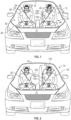
- FIG. 1 is a front cut-away view of a vehicle 10 depicting an interior of the vehicle and having an inflatable airbag assembly 100, according to an embodiment of the present disclosure.
- the vehicle 10 includes multiple vehicle seating positions.
- the vehicle 10 may include a driver vehicle seating position 20 and a passenger vehicle seating position 30 which are both located in a front row of the vehicle 10.
- the vehicle seating positions 20 and 30 are defined by a seat assembly 22, 32, which includes a seat 24, 34, a seatback 26, 36, and a restraint harness 28, 38 (e.g., a seat belt).
- Occupants 40, 50 are shown in the vehicle seating positions 20 and 30 for reference.
- the occupant 40 in the driver vehicle seating position 20 may be a driver of the vehicle 10.
- the vehicle 10 is a self-driving car, so the occupant 40 may simply be a passenger.
- the occupant 50 in the passenger vehicle seating position 30 may also be a passenger.
- the inflatable airbag assembly 100 comprises a housing 102 and an inflator 104 that is mounted between the occupant 40 in the driver vehicle seating position 20 and the occupant 50 in the passenger vehicle seating position 30.
- the housing 102 may be mounted to an inboard portion of the seatback 26 of the driver vehicle seating position 20.
- the inflator 104 may be coupled to the housing, and may be disposed partially or completely within the housing 102.
- the housing 102 may be mounted in a number of different positions between the occupant 40 in the driver vehicle seating position 20 and the occupant in the passenger vehicle seating position 30. In some embodiments, the housing 102 may be mounted to an inboard portion of the seat 24 of the driver vehicle seating position 20. In some embodiments, the housing 102 may be mounted to an inboard portion of the seatback 36 of the passenger vehicle seating position 30. In some embodiments, the housing 102 may be mounted to an inboard portion of the seat 34 of the passenger vehicle seating position 30. In some embodiments, the housing 102 may be mounted in a console 12 disposed between the driver vehicle seating position 20 and the passenger vehicle seating position 30.
- FIG. 1 and other figures may illustrate the occupants 40, 50 with their restraint harnesses 28, 38 employed, the operation of the inflatable airbag assembly 100 is independent of, and does not depend in any way on, the restraint harness 28 or 38.
- FIGS. 2 and 3 illustrate the inflatable airbag assembly 100 in a deployed configuration.
- FIG. 2 is a front view into the interior of the vehicle 10, showing the inflatable airbag assembly 100 deployed and at least partially inflated.
- This front view of FIG. 2 provides a rearward perspective of the interior of the vehicle 10.
- FIG. 3 is a rear view of the interior of the vehicle 10, showing the inflatable airbag assembly 100 deployed and at least partially inflated.
- This rear view of the interior of the vehicle 10 provides a forward perspective from behind the vehicle seating positions 20, 30 (see FIG. 1 ).
- the inflatable airbag assembly 100 may comprise a plurality of inflatable chambers.
- the inflatable airbag assembly 100 may comprise a first chamber 110, a second chamber 120, and a third chamber 130.
- the inflatable airbag assembly 100 may comprise a single chamber that accomplishes the functions of the three separate chambers 110, 120, 130.
- the chambers 110, 120, and 130 may be distinct chambers.
- the inflator 104 may simultaneously inflate the three chambers 110, 120, and 130 and in some embodiments, the inflator 104 may inflate the chambers 110, 120, and 130 in a specific order based on the flow of the inflation gas into the inflatable airbag assembly 100 or through vents (or a pattern or arrangement thereof) within the three chambers 110, 120, and 130.
- the second chamber 120 is shown in FIG. 2 and the third chamber 130 is shown in FIG. 3 .
- the chambers 110, 120, 130 may be inflated via an inflator port to an inflation pressure.
- the inflatable airbag assembly 100 may be deployed by action of the inflator 104, which may be activated by, for example, one or more sensors detecting the vehicle 10 being involved in a collision event.
- the inflator 104 may provide inflation gas to the inflatable airbag assembly 100 via the inflator port and thereby cause the inflatable airbag assembly 100 to deploy from the housing 102 and begin inflating.
- the first chamber 110 of the inflatable airbag assembly 100 may act as a barrier between the occupants 40, 50 in the driver vehicle seating position 20 and the passenger vehicle seating position 30.
- an occupant e.g., occupant 40
- another adjacent occupant e.g., occupant 50
- the deployed first chamber 110 acts as a barrier and prevents the occupant from hitting the other occupant.
- the first chamber 110 extends in a substantially longitudinal direction of the vehicle 10.
- the first chamber 110 extends longitudinally from a seatback 26 of the driver vehicle seating position 20 toward a dashboard (see FIG. 3 ) of the vehicle 10.
- the first chamber 110 may engage with the dashboard of the vehicle 10.
- the first chamber 110 may extend in a substantially vertical direction of the vehicle 10.
- the first chamber 110 may extend vertically from a seat 24 of the driver vehicle seating position 20 toward a roof 14 of the vehicle 10.
- the first chamber 110 engages with the roof 14 of the vehicle.
- the first chamber 110 extends above the seatback 26 of the vehicle but does not engage with the roof 14 of the vehicle. In other words, the height of the first chamber 110 may be high enough that the first chamber 110 acts as a barrier against a head of the nearest occupant 40.
- the first chamber 110 may have a number of different shapes. For example, in some embodiments, a side view of the first chamber 110 would reveal a rectangular shape. However, the present disclosure is not so limited, and the first chamber 110 may have an oval shape, a polygonal shape, a circular shape, and the like. The shape of the first chamber 110 simply provides a barrier to prevent contact between adjacent occupants 40, 50 during a collision event. The size and shape of the first chamber 110 is designed to meet the proposed Euro NCAP coverage requirements for far-side airbags.
- the second chamber 120 in the deployed configuration is partially deployed in front of the seatback 36 of the passenger vehicle seating position 30.
- the second chamber 120 may be configured to extend in front of the occupant 50, as illustrated in FIG. 2 .
- the deployment of the second chamber 120 may be reversed if the airbag assembly is disposed in the inboard side of the passenger vehicle seating position 30 in that the second chamber 120 is deployed in front of the seatback 26 of the driver vehicle seating position 20.
- the second chamber 120 may further include adaptive vents and/or internal pressure differential chambers which may prevent unwanted interaction with the passenger 50 if the passenger happens to be out of position.
- the deployment of the second chamber 120 occurs independent of the occupant presence/position and provides a reaction surface for the first chamber 110 to thereby limit or prevent occupant-to-occupant interaction.
- the second chamber 120 may have a variety of different shapes. In some embodiments, the second chamber 120 may have a circular shape. In other embodiments, the second chamber 120 may have a rectangular shape, a polygonal shape, a triangular shape, and the like.
- the third chamber 130 in the deployed configuration is partially deployed behind the seatback 36 of the passenger vehicle seating position 30.
- the deployment of the third chamber 130 may be reversed if the airbag assembly is disposed in the inboard side of the passenger vehicle seating position 30 in that the third chamber 130 is deployed in back of the seatback 26 of the driver vehicle seating position 20.
- the third chamber 130 may further include adaptive vents and/or internal pressure differential chambers which may prevent unwanted interaction with out-of-position passengers in a second row of the vehicle 10.
- the third chamber 130 may have a variety of different shapes. In some embodiments, the third chamber 130 may have a circular shape. In other embodiments, the second chamber 120 may have a rectangular shape, a polygonal shape, a triangular shape, and the like. In some embodiments, the third chamber 130 is smaller than the second chamber 120. In some embodiments, the second chamber 120 may extend higher vertically than the third chamber 130. The third chamber 130 is designed to require a minimum amount of inflation gas as possible.
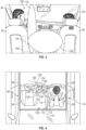
- FIG. 4 illustrates a top view of the inflatable airbag assembly 100 in the deployed configuration.
- the first chamber 110 extends in a longitudinal direction of the vehicle 10 from the seatback 36 of the driver vehicle seating position 20 toward the dashboard of the vehicle 10.
- the first chamber 110 includes an outboard side 112 and an inboard side 114.
- a longitudinal axis 116 of the first chamber 110 is substantially parallel to the longitudinal direction of the vehicle 10.
- the second chamber 120 is partially disposed in front of the seatback 36 of the adjacent seating position 30 and the third chamber 130 is partially disposed behind the seatback 36 of the adjacent seating position 30.
- the second chamber 120 includes a front face 122 and a back face 124, and a tip 126.
- the second chamber 120 is disposed on an inboard side 114 of the first chamber 110.
- the second chamber 120 is oriented at a first angle ⁇ 1 , such that it extends away from the first chamber 110 in a direction transverse (nonparallel) to an axis 116 of the first chamber 110.
- the third chamber 130 includes a front face 132 and a back face 134, and a tip 136.
- the third chamber 130 is disposed on an inboard side 114 of the first chamber 110.
- the third chamber 130 is oriented at a second angle ⁇ 2 , such that it extends away from the first chamber 110 in a direction transverse to the axis 116 of the first chamber 110 and transverse to the second chamber 120.
- the first angle ⁇ 1 is different from the second angle ⁇ 2 .
- the first angle ⁇ 1 forms an acute angle relative to the axis 116 of the first chamber 110 and the second angle ⁇ 2 forms an obtuse angle relative to the axis 116 of the first chamber 110.
- the difference between the second angle ⁇ 2 and the first angle ⁇ 1 may be less than 90 degrees.
- the orientations of the second chamber 120 and the third chamber 130 provide a forked configuration between the chambers 120 and 130.
- the inflatable airbag assembly 100 further comprises a tether 140 that couples the second chamber 120 to the third chamber 130.
- a first end 142 of the tether 140 couples to a rear side 124 of the second chamber 120 and the second end 144 of the tether couples to a forward side 132 of the third chamber 130.
- the first end 142 of the tether 140 is coupled near a tip 126 of the second chamber 120.
- the second end 144 of the tether 140 is coupled near a tip 136 of the third chamber 130.
- the inflatable airbag assembly 100 may comprise a plurality of tethers that are coupled to the second chamber 120 and the third chamber 130.
- Each tether may have a different length. For example, a tether closer to the adjacent seatback 36 may be longer than a tether farther away from the adjacent seatback 36.
- the second chamber 120, the third chamber 130, and the tether 140 act together to stabilize the first chamber 110 during a collision event.
- the tether 140 engages with the adjacent seatback, in the illustrated embodiment, and the adjacent seatback is seatback 36 of the passenger vehicle seating position 30.
- the tether 140 pulls the second chamber 120 toward the third chamber 130.
- the second chamber 120 and the third chamber 130 pinch the adjacent seatback 36.
- the second chamber 120 engages a front surface of the seatback 36 and the third chamber 130 engages a back surface of the seatback 36.
- FIG. 4 illustrates that the driver vehicle seating position 20 and the passenger vehicle seating position 30 are laterally aligned.
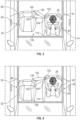
- One of the benefits of the inflatable airbag assembly 100 is that the inflatable airbag assembly 100 is designed to deploy correctly whether or not the vehicle seating positions 20, 30 are laterally aligned.
- the driver vehicle seating position 20 is not laterally aligned with the passenger vehicle seating position 30.
- the driver vehicle seating position 20 is disposed longitudinally in front of the passenger vehicle seating position 30.
- the inflatable airbag assembly 100 deploys correctly because the forked configuration of the second chamber 120, the third chamber 130, and the tether 140 are able to engage with the seatback 36 of the adjacent vehicle seating position, e.g., the passenger vehicle seating position 30.
- the driver vehicle seating position 20 is also not laterally aligned with the passenger vehicle seating position 30.
- the driver vehicle seating position 20 is disposed longitudinally in back of or behind the passenger vehicle seating position 30.
- the inflatable airbag assembly 100 deploys correctly because the forked configuration of the second chamber 120, the third chamber 130, and the tether 140 are able to engage with the seatback 36 of the adjacent vehicle seating position, e.g., the passenger vehicle seating position 30.
- FIGS. 4-6 do not illustrate the passenger 50 in the passenger vehicle seating position 30.
- the inflatable airbag assembly 100 is not dependent on a passenger being present in or absent from the passenger vehicle seating position 30.
- the passenger vehicle seating position 30 may include a sensor to detect whether the passenger 50 is sitting in the passenger vehicle seating position 30. In some embodiments, if the sensor detects the passenger 50 the inflatable airbag assembly 100 deploys, and if the sensor does not detect the passenger 50 the inflatable airbag assembly 100 does not deploy. In some embodiments, the inflatable airbag assembly 100 will deploy whether or not the passenger 50 is in the passenger vehicle seating position 30.
- Coupled to and “in communication with” refer to any form of interaction between two or more entities, including mechanical, electrical, magnetic, electromagnetic, fluid, and thermal interaction. Two components may be coupled to each other even though they are not in direct contact with each other.
- the terms “abut” and “abutting” refer to items that are in direct physical contact with each other, although the items may not necessarily be attached together.
- inboard refers to a direction toward a centerline of a vehicle and “outboard” refers to a direction out of the vehicle and away from a centerline of the vehicle.
- fluid communication is used in its ordinary sense, and is broad enough to refer to arrangements in which a fluid (e.g., a gas or a liquid) can flow from one element to another element when the elements are in fluid communication with each other.
- a fluid e.g., a gas or a liquid
- a and “an” can be described as one, but not limited to one.
- the disclosure may recite an airbag having "a chamber,” the disclosure also contemplates that the airbag can have two or more chambers.
- longitudinal and longitudinal refer to a direction or orientation extending or spanning between a front of a vehicle and a rear of the vehicle.
- the terms “forward” and “rearward” are used with reference to the front and back of the relevant vehicle.
- an airbag cushion that deploys in a rearward direction deploys toward the back of a vehicle.
- other reference terms, such as “horizontal,” are used relative to a vehicle in which an airbag assembly is installed, unless it is clear from context that a different reference frame is intended.
- a term such as “horizontal” is used relative to the vehicle, whether or not the vehicle itself is oriented horizontally (e.g., is positioned upright on level ground) or angled relative to true horizontal (e.g., is positioned on a hill).
- vehicle seating position refers to the position in which an occupant is generally positioned when seated in a seat of a vehicle.
- occupant refers to a person or crash test dummy within a vehicle.
Landscapes
- Engineering & Computer Science (AREA)
- Mechanical Engineering (AREA)
- Air Bags (AREA)
Claims (15)
- Fahrzeug (10), das einen Sitz (20) und einer Airbag-Anordnung (100) aufweist, die Airbag-Anordnung (100) umfassend:ein Gehäuse (102), das in einem inneren Teil des Sitzes (20) montiert ist;eine Gasgeneratoranordnung (104), die mindestens teilweise innerhalb des Gehäuses (102) eingerichtet ist; undeinen Airbag in einem verpackten Zustand innerhalb des Gehäuses (102), wobei der Airbag konfiguriert ist, um Füllgas aufzunehmen, um sich auszudehnen und aus dem Gehäuse in einen entfalteten Zustand zu entfalten, wobei der Airbag in dem entfalteten Zustand eine erste aufblasbare Kammer (110) umfasst, die eine Längsachse (116) aufweist und sich in einer Längsrichtung des Fahrzeugs (10) erstreckt; und dadurch gekennzeichnet, dass der Airbag in dem entfalteten Zustand umfasst:eine zweite aufblasbare Kammer (120), die an einer inneren Seite (114) der ersten Kammer (110) eingerichtet und in einem ersten Winkel (θ1) zu der Längsachse (116) der ersten Kammer (110) derart ausgerichtet ist, dass sich die zweite Kammer (120) in einer Richtung quer zu der Längsachse (116) der ersten Kammer (110) von der ersten Kammer (110) weg erstreckt; undeine dritte aufblasbare Kammer (130), die an einer inneren Seite (114) der ersten Kammer (110) eingerichtet und in einem zweiten Winkel (θ2) zu der Längsachse der ersten Kammer (110) derart ausgerichtet ist, dass sich die dritte Kammer (130) von der ersten Kammer (110) weg in eine Richtung quer zu der Längsachse (116) der ersten Kammer (110) und quer zu der zweiten Kammer (120) erstreckt,wobei der erste Winkel (θ1) sich von dem zweiten Winkel (θ2) unterscheidet.
- Fahrzeug (10) nach Anspruch 1, wobei der Sitz (20) eine Sitzlehne (26) umfasst und wobei die zweite aufblasbare Kammer (120) vor einer zweiten Sitzlehne (36) seitlich angrenzend an dem Sitz (20) eingerichtet ist.
- Fahrzeug (10) nach einem der Ansprüche 1 und 2, wobei die dritte aufblasbare Kammer (130) hinter einer zweiten Sitzlehne (36) seitlich angrenzend an dem Sitz (20) eingerichtet ist.
- Fahrzeug (10) nach einem der Ansprüche 1 bis 3, wobei die zweite aufblasbare Kammer (120) und die dritte aufblasbare Kammer (130) eine gegabelte Konfiguration ausbilden.
- Fahrzeug (10) nach einem der Ansprüche 1 bis 4, ferner umfassend einen Haltegurt (140), wobei ein erstes Ende (142) des Haltegurtes (140) mit der zweiten aufblasbaren Kammer (120) gekoppelt ist und ein zweites Ende (144) des Haltegurtes (140) mit der dritten aufblasbaren Kammer (130) gekoppelt ist.
- Fahrzeug (10) nach Anspruch 5, wobei der Haltegurt (140) in eine zweite Sitzlehne (36) eines zweiten Sitzes (30) eingreift, der seitlich angrenzend an dem Sitz (20) liegt, und wobei der Eingriff des Haltegurtes (140) in die zweite Sitzlehne (36) die zweite aufblasbare Kammer (120) und die dritte aufblasbare Kammer (130) aufeinander zu zieht.
- Fahrzeug (10) nach Anspruch 6, wobei der Eingriff des Haltegurtes (140) in die zweite Sitzlehne (36) die zweite aufblasbare Kammer (120) mit einer vorderen Oberfläche der zweiten Sitzlehne (36) in Eingriff nimmt und die dritte aufblasbare Kammer (130) mit einer hinteren Oberfläche der zweiten Sitzlehne (36) in Eingriff nimmt.
- Fahrzeug (10) nach Anspruch 5, wobei der Haltegurt (140) in eine zweite Sitzlehne (36) eines zweiten Sitzes (30) eingreift, der seitlich angrenzend an dem Sitz (20) liegt, und wobei der Eingriff des Haltegurtes (140) in die zweite Sitzlehne (36) veranlasst, dass die zweite aufblasbare Kammer (120) und die dritte aufblasbare Kammer (130) die zweite Sitzlehne (36) einklemmen.
- Fahrzeug (10) nach Anspruch 8, wobei die zweite aufblasbare Kammer (120) und die dritte aufblasbare Kammer (130) die zweite Sitzlehne (36) einklemmen, wenn der zweite Sitz (30) nicht seitlich mit der Sitzlehne (26) angeglichen ist.
- Fahrzeug (10) nach Anspruch 8, wobei die zweite aufblasbare Kammer (120) und die dritte aufblasbare Kammer (130) die zweite Sitzlehne (36) einklemmen, wenn der zweite Sitz (30) vor der Sitzlehne (26) längs eingerichtet ist.
- Fahrzeug (10) nach Anspruch 8, wobei die zweite aufblasbare Kammer (120) und die dritte aufblasbare Kammer (130) die zweite Sitzlehne (36) einklemmen, wenn der zweite Sitz (30) hinter der Sitzlehne (26) längs eingerichtet ist.
- Fahrzeug (10) nach einem der Ansprüche 1 bis 11, ferner umfassend eine Vielzahl von Haltegurten (140), die die zweite aufblasbare Kammer (120) mit der dritten aufblasbaren Kammer (130) koppeln.
- Fahrzeug (10) nach einem der Ansprüche 1 bis 12, wobei der Sitz (20) ein Fahrersitz ist.
- Fahrzeug (10) nach einem der Ansprüche 1 bis 13, wobei der Sitz (30) ein Beifahrersitz ist.
- Fahrzeug (10) nach einem der Ansprüche 1 bis 14, wobei sich die erste aufblasbare Kammer (110) von einer Sitzfläche (24) des Sitzes (20) zu einer Oberseite der Sitzlehne (26) des Sitzes (20) vertikal erstreckt.
Applications Claiming Priority (2)
| Application Number | Priority Date | Filing Date | Title |
|---|---|---|---|
| US16/742,680 US11130463B2 (en) | 2020-01-14 | 2020-01-14 | Forked far-side airbag assembly |
| PCT/US2021/012832 WO2021146121A1 (en) | 2020-01-14 | 2021-01-08 | Forked far-side airbag assembly |
Publications (2)
| Publication Number | Publication Date |
|---|---|
| EP4090559A1 EP4090559A1 (de) | 2022-11-23 |
| EP4090559B1 true EP4090559B1 (de) | 2024-12-25 |
Family
ID=74550737
Family Applications (1)
| Application Number | Title | Priority Date | Filing Date |
|---|---|---|---|
| EP21703340.6A Active EP4090559B1 (de) | 2020-01-14 | 2021-01-08 | Fahrzeug mit einem sitz und einer airbaganordnung |
Country Status (6)
| Country | Link |
|---|---|
| US (1) | US11130463B2 (de) |
| EP (1) | EP4090559B1 (de) |
| JP (1) | JP7530429B2 (de) |
| KR (1) | KR102708046B1 (de) |
| CN (1) | CN114929528B (de) |
| WO (1) | WO2021146121A1 (de) |
Families Citing this family (7)
| Publication number | Priority date | Publication date | Assignee | Title |
|---|---|---|---|---|
| US11214225B2 (en) * | 2017-08-01 | 2022-01-04 | Autoliv Development Ab | Passenger protection apparatus |
| KR102340676B1 (ko) * | 2019-02-12 | 2021-12-17 | 아우토리브 디벨롭먼트 아베 | 에어백 장치, 에어백 장치의 제조 방법 및 에어백 장치의 전개 방법 |
| US11713018B1 (en) * | 2020-05-13 | 2023-08-01 | Apple Inc. | Deployable structure with main chamber and reaction chamber |
| US11433848B1 (en) * | 2021-06-15 | 2022-09-06 | Ford Global Technologies, Llc | Airbags supported by center console with non-inflatable panel |
| US11787361B1 (en) * | 2022-12-15 | 2023-10-17 | Ford Global Technologies, Llc | Selectively inflatable airbag side chambers |
| JP7764849B2 (ja) * | 2022-12-26 | 2025-11-06 | トヨタ自動車株式会社 | 車両用乗員拘束装置及びファーサイドエアバッグ折り畳み方法 |
| US12043202B1 (en) * | 2023-06-16 | 2024-07-23 | Ford Global Technologies, Llc | Seat airbag with pyrotechnic retractor |
Family Cites Families (19)
| Publication number | Priority date | Publication date | Assignee | Title |
|---|---|---|---|---|
| DE19816075A1 (de) | 1998-04-09 | 1999-10-14 | Volkswagen Ag | Sicherheitsvorrichtung für ein Kraftfahrzeug mit einem Mehrkammer-Airbag |
| JP4400495B2 (ja) * | 2004-05-27 | 2010-01-20 | 豊田合成株式会社 | サイドエアバッグ装置 |
| JP5177220B2 (ja) * | 2008-10-29 | 2013-04-03 | トヨタ自動車株式会社 | 車両用座席間エアバッグ装置 |
| DE102010027401B4 (de) | 2010-07-15 | 2022-05-12 | Autoliv Development Ab | Seitengassack mit seitlicher Abstützung |
| JP2014076702A (ja) * | 2012-10-09 | 2014-05-01 | Toyota Motor Corp | 車両用乗員保護装置 |
| WO2017143010A1 (en) * | 2016-02-16 | 2017-08-24 | Tk Holdings Inc. | Center side airbag module |
| KR102547636B1 (ko) * | 2016-05-20 | 2023-06-26 | 현대모비스 주식회사 | 차량용 에어백장치 |
| JP6394657B2 (ja) * | 2016-07-22 | 2018-09-26 | トヨタ自動車株式会社 | 車両用乗員拘束装置 |
| CN106184103B (zh) * | 2016-08-02 | 2018-03-06 | 锦州锦恒汽车安全系统有限公司 | 一种互为支撑的汽车安全气囊系统 |
| JP2018127156A (ja) * | 2017-02-10 | 2018-08-16 | 三菱自動車工業株式会社 | エアバッグ装置 |
| WO2018179850A1 (ja) * | 2017-03-30 | 2018-10-04 | オートリブ ディベロップメント エービー | 乗員保護装置 |
| KR102530685B1 (ko) * | 2017-08-18 | 2023-05-11 | 현대자동차주식회사 | 차량용 에어백 |
| KR102452467B1 (ko) | 2017-08-24 | 2022-10-11 | 현대자동차주식회사 | 차량용 에어백 |
| US10703325B2 (en) * | 2017-11-27 | 2020-07-07 | Autoliv Asp, Inc. | Multi-chambered side airbag assemblies |
| DE102018120880A1 (de) * | 2017-12-08 | 2019-06-13 | Trw Automotive Gmbh | Seitengassack und Fahrzeuginsassen-Rückhaltesystem mit einem Seitengassack |
| DE102018202417A1 (de) | 2018-02-16 | 2019-08-22 | Takata AG | Fahrzeuginsassen-Rückhaltesystem |
| KR102565349B1 (ko) * | 2018-03-19 | 2023-08-14 | 현대자동차주식회사 | 차량용 에어백 |
| US10717405B2 (en) * | 2018-03-19 | 2020-07-21 | Rivian Ip Holdings, Llc | Airbag arrangement for protection in a far-side vehicular crash |
| JP6691569B2 (ja) * | 2018-03-30 | 2020-04-28 | 株式会社Subaru | 車両の乗員保護装置 |
-
2020
- 2020-01-14 US US16/742,680 patent/US11130463B2/en active Active
-
2021
- 2021-01-08 JP JP2022541603A patent/JP7530429B2/ja active Active
- 2021-01-08 KR KR1020227027472A patent/KR102708046B1/ko active Active
- 2021-01-08 CN CN202180008122.3A patent/CN114929528B/zh active Active
- 2021-01-08 WO PCT/US2021/012832 patent/WO2021146121A1/en not_active Ceased
- 2021-01-08 EP EP21703340.6A patent/EP4090559B1/de active Active
Also Published As
| Publication number | Publication date |
|---|---|
| JP7530429B2 (ja) | 2024-08-07 |
| JP2023510722A (ja) | 2023-03-15 |
| US11130463B2 (en) | 2021-09-28 |
| US20210213904A1 (en) | 2021-07-15 |
| WO2021146121A1 (en) | 2021-07-22 |
| KR102708046B1 (ko) | 2024-09-23 |
| KR20220119742A (ko) | 2022-08-30 |
| EP4090559A1 (de) | 2022-11-23 |
| CN114929528B (zh) | 2023-10-31 |
| CN114929528A (zh) | 2022-08-19 |
Similar Documents
| Publication | Publication Date | Title |
|---|---|---|
| EP4090559B1 (de) | Fahrzeug mit einem sitz und einer airbaganordnung | |
| CN109249889B (zh) | 正面安全气囊组件 | |
| US10336278B2 (en) | Inflatable airbag harness assemblies | |
| US10632956B2 (en) | Inflatable safety restraint system for protecting a rear seat occupant | |
| EP3280620B1 (de) | Airbaganordnungen für fahrzeuge mit grosszügigem beinraum | |
| EP3152087B1 (de) | Doppelpolsterairbag mit unabhängiger befüllung | |
| US10583799B2 (en) | Overhead inflatable airbag assembly | |
| EP4019345A1 (de) | Airbagvorrichtung | |
| EP3802231B1 (de) | Seitenairbaganordnung | |
| US11878647B2 (en) | Occupant restraint system | |
| WO2022225722A1 (en) | Roof airbag for a vehicle | |
| US20080179864A1 (en) | Airbag apparatus | |
| EP3959105B1 (de) | Seitenairbaganordnung | |
| US11865991B1 (en) | Overhead airbag cushions and related systems | |
| EP4259491B1 (de) | Seitenairbag-baugruppen mit kissen und segel | |
| JP2024522999A (ja) | 展開支援ラッパーを備えた前面エアバッグシステム | |
| US12269413B1 (en) | Active control of anti-submarining automotive protective devices | |
| EP4477479B1 (de) | Airbag für ein kraftfahrzeug | |
| US11192512B2 (en) | Airbag arrangement | |
| JP3843985B2 (ja) | 自動車の側突時における乗員保護装置 | |
| JP2025512365A (ja) | 車両の側面エアバッグ装置 |
Legal Events
| Date | Code | Title | Description |
|---|---|---|---|
| STAA | Information on the status of an ep patent application or granted ep patent |
Free format text: STATUS: UNKNOWN |
|
| STAA | Information on the status of an ep patent application or granted ep patent |
Free format text: STATUS: THE INTERNATIONAL PUBLICATION HAS BEEN MADE |
|
| PUAI | Public reference made under article 153(3) epc to a published international application that has entered the european phase |
Free format text: ORIGINAL CODE: 0009012 |
|
| STAA | Information on the status of an ep patent application or granted ep patent |
Free format text: STATUS: REQUEST FOR EXAMINATION WAS MADE |
|
| 17P | Request for examination filed |
Effective date: 20220728 |
|
| AK | Designated contracting states |
Kind code of ref document: A1 Designated state(s): AL AT BE BG CH CY CZ DE DK EE ES FI FR GB GR HR HU IE IS IT LI LT LU LV MC MK MT NL NO PL PT RO RS SE SI SK SM TR |
|
| DAV | Request for validation of the european patent (deleted) | ||
| DAX | Request for extension of the european patent (deleted) | ||
| GRAP | Despatch of communication of intention to grant a patent |
Free format text: ORIGINAL CODE: EPIDOSNIGR1 |
|
| STAA | Information on the status of an ep patent application or granted ep patent |
Free format text: STATUS: GRANT OF PATENT IS INTENDED |
|
| INTG | Intention to grant announced |
Effective date: 20240724 |
|
| RIN1 | Information on inventor provided before grant (corrected) |
Inventor name: SMITH, ADAM Inventor name: WISCOMBE, DEREK JOHN Inventor name: HOLLIDAY, ANDREW LAWRENCE Inventor name: PARKER, DON LARRY |
|
| GRAS | Grant fee paid |
Free format text: ORIGINAL CODE: EPIDOSNIGR3 |
|
| GRAA | (expected) grant |
Free format text: ORIGINAL CODE: 0009210 |
|
| STAA | Information on the status of an ep patent application or granted ep patent |
Free format text: STATUS: THE PATENT HAS BEEN GRANTED |
|
| AK | Designated contracting states |
Kind code of ref document: B1 Designated state(s): AL AT BE BG CH CY CZ DE DK EE ES FI FR GB GR HR HU IE IS IT LI LT LU LV MC MK MT NL NO PL PT RO RS SE SI SK SM TR |
|
| REG | Reference to a national code |
Ref country code: GB Ref legal event code: FG4D |
|
| REG | Reference to a national code |
Ref country code: CH Ref legal event code: EP |
|
| REG | Reference to a national code |
Ref country code: DE Ref legal event code: R096 Ref document number: 602021023844 Country of ref document: DE |
|
| REG | Reference to a national code |
Ref country code: IE Ref legal event code: FG4D |
|
| REG | Reference to a national code |
Ref country code: LT Ref legal event code: MG9D |
|
| PG25 | Lapsed in a contracting state [announced via postgrant information from national office to epo] |
Ref country code: HR Free format text: LAPSE BECAUSE OF FAILURE TO SUBMIT A TRANSLATION OF THE DESCRIPTION OR TO PAY THE FEE WITHIN THE PRESCRIBED TIME-LIMIT Effective date: 20241225 |
|
| PGFP | Annual fee paid to national office [announced via postgrant information from national office to epo] |
Ref country code: DE Payment date: 20250129 Year of fee payment: 5 |
|
| PG25 | Lapsed in a contracting state [announced via postgrant information from national office to epo] |
Ref country code: FI Free format text: LAPSE BECAUSE OF FAILURE TO SUBMIT A TRANSLATION OF THE DESCRIPTION OR TO PAY THE FEE WITHIN THE PRESCRIBED TIME-LIMIT Effective date: 20241225 |
|
| PG25 | Lapsed in a contracting state [announced via postgrant information from national office to epo] |
Ref country code: BG Free format text: LAPSE BECAUSE OF FAILURE TO SUBMIT A TRANSLATION OF THE DESCRIPTION OR TO PAY THE FEE WITHIN THE PRESCRIBED TIME-LIMIT Effective date: 20241225 |
|
| PG25 | Lapsed in a contracting state [announced via postgrant information from national office to epo] |
Ref country code: NO Free format text: LAPSE BECAUSE OF FAILURE TO SUBMIT A TRANSLATION OF THE DESCRIPTION OR TO PAY THE FEE WITHIN THE PRESCRIBED TIME-LIMIT Effective date: 20250325 |
|
| PG25 | Lapsed in a contracting state [announced via postgrant information from national office to epo] |
Ref country code: GR Free format text: LAPSE BECAUSE OF FAILURE TO SUBMIT A TRANSLATION OF THE DESCRIPTION OR TO PAY THE FEE WITHIN THE PRESCRIBED TIME-LIMIT Effective date: 20250326 Ref country code: LV Free format text: LAPSE BECAUSE OF FAILURE TO SUBMIT A TRANSLATION OF THE DESCRIPTION OR TO PAY THE FEE WITHIN THE PRESCRIBED TIME-LIMIT Effective date: 20241225 |
|
| PGFP | Annual fee paid to national office [announced via postgrant information from national office to epo] |
Ref country code: AT Payment date: 20250417 Year of fee payment: 5 |
|
| PGFP | Annual fee paid to national office [announced via postgrant information from national office to epo] |
Ref country code: FR Payment date: 20250127 Year of fee payment: 5 |
|
| PGFP | Annual fee paid to national office [announced via postgrant information from national office to epo] |
Ref country code: GB Payment date: 20250121 Year of fee payment: 5 |
|
| PG25 | Lapsed in a contracting state [announced via postgrant information from national office to epo] |
Ref country code: RS Free format text: LAPSE BECAUSE OF FAILURE TO SUBMIT A TRANSLATION OF THE DESCRIPTION OR TO PAY THE FEE WITHIN THE PRESCRIBED TIME-LIMIT Effective date: 20250325 |
|
| REG | Reference to a national code |
Ref country code: NL Ref legal event code: MP Effective date: 20241225 |
|
| PG25 | Lapsed in a contracting state [announced via postgrant information from national office to epo] |
Ref country code: NL Free format text: LAPSE BECAUSE OF FAILURE TO SUBMIT A TRANSLATION OF THE DESCRIPTION OR TO PAY THE FEE WITHIN THE PRESCRIBED TIME-LIMIT Effective date: 20241225 |
|
| REG | Reference to a national code |
Ref country code: AT Ref legal event code: MK05 Ref document number: 1753922 Country of ref document: AT Kind code of ref document: T Effective date: 20241225 |
|
| PG25 | Lapsed in a contracting state [announced via postgrant information from national office to epo] |
Ref country code: SM Free format text: LAPSE BECAUSE OF FAILURE TO SUBMIT A TRANSLATION OF THE DESCRIPTION OR TO PAY THE FEE WITHIN THE PRESCRIBED TIME-LIMIT Effective date: 20241225 |
|
| PG25 | Lapsed in a contracting state [announced via postgrant information from national office to epo] |
Ref country code: PL Free format text: LAPSE BECAUSE OF FAILURE TO SUBMIT A TRANSLATION OF THE DESCRIPTION OR TO PAY THE FEE WITHIN THE PRESCRIBED TIME-LIMIT Effective date: 20241225 |
|
| PG25 | Lapsed in a contracting state [announced via postgrant information from national office to epo] |
Ref country code: ES Free format text: LAPSE BECAUSE OF FAILURE TO SUBMIT A TRANSLATION OF THE DESCRIPTION OR TO PAY THE FEE WITHIN THE PRESCRIBED TIME-LIMIT Effective date: 20241225 |
|
| PG25 | Lapsed in a contracting state [announced via postgrant information from national office to epo] |
Ref country code: IS Free format text: LAPSE BECAUSE OF FAILURE TO SUBMIT A TRANSLATION OF THE DESCRIPTION OR TO PAY THE FEE WITHIN THE PRESCRIBED TIME-LIMIT Effective date: 20250425 |
|
| PG25 | Lapsed in a contracting state [announced via postgrant information from national office to epo] |
Ref country code: PT Free format text: LAPSE BECAUSE OF FAILURE TO SUBMIT A TRANSLATION OF THE DESCRIPTION OR TO PAY THE FEE WITHIN THE PRESCRIBED TIME-LIMIT Effective date: 20250428 |
|
| PG25 | Lapsed in a contracting state [announced via postgrant information from national office to epo] |
Ref country code: EE Free format text: LAPSE BECAUSE OF FAILURE TO SUBMIT A TRANSLATION OF THE DESCRIPTION OR TO PAY THE FEE WITHIN THE PRESCRIBED TIME-LIMIT Effective date: 20241225 |
|
| PG25 | Lapsed in a contracting state [announced via postgrant information from national office to epo] |
Ref country code: RO Free format text: LAPSE BECAUSE OF FAILURE TO SUBMIT A TRANSLATION OF THE DESCRIPTION OR TO PAY THE FEE WITHIN THE PRESCRIBED TIME-LIMIT Effective date: 20241225 Ref country code: AT Free format text: LAPSE BECAUSE OF FAILURE TO SUBMIT A TRANSLATION OF THE DESCRIPTION OR TO PAY THE FEE WITHIN THE PRESCRIBED TIME-LIMIT Effective date: 20241225 |
|
| PG25 | Lapsed in a contracting state [announced via postgrant information from national office to epo] |
Ref country code: SK Free format text: LAPSE BECAUSE OF FAILURE TO SUBMIT A TRANSLATION OF THE DESCRIPTION OR TO PAY THE FEE WITHIN THE PRESCRIBED TIME-LIMIT Effective date: 20241225 |
|
| PG25 | Lapsed in a contracting state [announced via postgrant information from national office to epo] |
Ref country code: CZ Free format text: LAPSE BECAUSE OF FAILURE TO SUBMIT A TRANSLATION OF THE DESCRIPTION OR TO PAY THE FEE WITHIN THE PRESCRIBED TIME-LIMIT Effective date: 20241225 |
|
| PG25 | Lapsed in a contracting state [announced via postgrant information from national office to epo] |
Ref country code: IT Free format text: LAPSE BECAUSE OF FAILURE TO SUBMIT A TRANSLATION OF THE DESCRIPTION OR TO PAY THE FEE WITHIN THE PRESCRIBED TIME-LIMIT Effective date: 20241225 |
|
| REG | Reference to a national code |
Ref country code: CH Ref legal event code: PL |
|
| PG25 | Lapsed in a contracting state [announced via postgrant information from national office to epo] |
Ref country code: SE Free format text: LAPSE BECAUSE OF FAILURE TO SUBMIT A TRANSLATION OF THE DESCRIPTION OR TO PAY THE FEE WITHIN THE PRESCRIBED TIME-LIMIT Effective date: 20241225 |
|
| PG25 | Lapsed in a contracting state [announced via postgrant information from national office to epo] |
Ref country code: LU Free format text: LAPSE BECAUSE OF NON-PAYMENT OF DUE FEES Effective date: 20250108 Ref country code: MC Free format text: LAPSE BECAUSE OF FAILURE TO SUBMIT A TRANSLATION OF THE DESCRIPTION OR TO PAY THE FEE WITHIN THE PRESCRIBED TIME-LIMIT Effective date: 20241225 |
|
| REG | Reference to a national code |
Ref country code: DE Ref legal event code: R097 Ref document number: 602021023844 Country of ref document: DE |
|
| PG25 | Lapsed in a contracting state [announced via postgrant information from national office to epo] |
Ref country code: DK Free format text: LAPSE BECAUSE OF FAILURE TO SUBMIT A TRANSLATION OF THE DESCRIPTION OR TO PAY THE FEE WITHIN THE PRESCRIBED TIME-LIMIT Effective date: 20241225 |
|
| PG25 | Lapsed in a contracting state [announced via postgrant information from national office to epo] |
Ref country code: BE Free format text: LAPSE BECAUSE OF NON-PAYMENT OF DUE FEES Effective date: 20250131 |
|
| PG25 | Lapsed in a contracting state [announced via postgrant information from national office to epo] |
Ref country code: CH Free format text: LAPSE BECAUSE OF NON-PAYMENT OF DUE FEES Effective date: 20250131 |
|
| REG | Reference to a national code |
Ref country code: BE Ref legal event code: MM Effective date: 20250131 |
|
| PLBE | No opposition filed within time limit |
Free format text: ORIGINAL CODE: 0009261 |
|
| STAA | Information on the status of an ep patent application or granted ep patent |
Free format text: STATUS: NO OPPOSITION FILED WITHIN TIME LIMIT |
|
| 26N | No opposition filed |
Effective date: 20250926 |
|
| PG25 | Lapsed in a contracting state [announced via postgrant information from national office to epo] |
Ref country code: IE Free format text: LAPSE BECAUSE OF NON-PAYMENT OF DUE FEES Effective date: 20250108 |