EP4259491B1 - Seitenairbag-baugruppen mit kissen und segel - Google Patents
Seitenairbag-baugruppen mit kissen und segel Download PDFInfo
- Publication number
- EP4259491B1 EP4259491B1 EP21815858.2A EP21815858A EP4259491B1 EP 4259491 B1 EP4259491 B1 EP 4259491B1 EP 21815858 A EP21815858 A EP 21815858A EP 4259491 B1 EP4259491 B1 EP 4259491B1
- Authority
- EP
- European Patent Office
- Prior art keywords
- cushion
- inflatable airbag
- occupant
- vehicle
- panel
- Prior art date
- Legal status (The legal status is an assumption and is not a legal conclusion. Google has not performed a legal analysis and makes no representation as to the accuracy of the status listed.)
- Active
Links
Images

Classifications
-
- B—PERFORMING OPERATIONS; TRANSPORTING
- B60—VEHICLES IN GENERAL
- B60R—VEHICLES, VEHICLE FITTINGS, OR VEHICLE PARTS, NOT OTHERWISE PROVIDED FOR
- B60R21/00—Arrangements or fittings on vehicles for protecting or preventing injuries to occupants or pedestrians in case of accidents or other traffic risks
- B60R21/02—Occupant safety arrangements or fittings, e.g. crash pads
- B60R21/16—Inflatable occupant restraints or confinements designed to inflate upon impact or impending impact, e.g. air bags
- B60R21/20—Arrangements for storing inflatable members in their non-use or deflated condition; Arrangement or mounting of air bag modules or components
- B60R21/207—Arrangements for storing inflatable members in their non-use or deflated condition; Arrangement or mounting of air bag modules or components in vehicle seats
-
- B—PERFORMING OPERATIONS; TRANSPORTING
- B60—VEHICLES IN GENERAL
- B60R—VEHICLES, VEHICLE FITTINGS, OR VEHICLE PARTS, NOT OTHERWISE PROVIDED FOR
- B60R21/00—Arrangements or fittings on vehicles for protecting or preventing injuries to occupants or pedestrians in case of accidents or other traffic risks
- B60R21/02—Occupant safety arrangements or fittings, e.g. crash pads
- B60R21/16—Inflatable occupant restraints or confinements designed to inflate upon impact or impending impact, e.g. air bags
- B60R21/23—Inflatable members
- B60R21/231—Inflatable members characterised by their shape, construction or spatial configuration
- B60R21/23138—Inflatable members characterised by their shape, construction or spatial configuration specially adapted for side protection
-
- B—PERFORMING OPERATIONS; TRANSPORTING
- B60—VEHICLES IN GENERAL
- B60R—VEHICLES, VEHICLE FITTINGS, OR VEHICLE PARTS, NOT OTHERWISE PROVIDED FOR
- B60R21/00—Arrangements or fittings on vehicles for protecting or preventing injuries to occupants or pedestrians in case of accidents or other traffic risks
- B60R21/02—Occupant safety arrangements or fittings, e.g. crash pads
- B60R21/16—Inflatable occupant restraints or confinements designed to inflate upon impact or impending impact, e.g. air bags
- B60R21/23—Inflatable members
- B60R21/231—Inflatable members characterised by their shape, construction or spatial configuration
- B60R21/233—Inflatable members characterised by their shape, construction or spatial configuration comprising a plurality of individual compartments; comprising two or more bag-like members, one within the other
-
- B—PERFORMING OPERATIONS; TRANSPORTING
- B60—VEHICLES IN GENERAL
- B60R—VEHICLES, VEHICLE FITTINGS, OR VEHICLE PARTS, NOT OTHERWISE PROVIDED FOR
- B60R21/00—Arrangements or fittings on vehicles for protecting or preventing injuries to occupants or pedestrians in case of accidents or other traffic risks
- B60R21/02—Occupant safety arrangements or fittings, e.g. crash pads
- B60R21/16—Inflatable occupant restraints or confinements designed to inflate upon impact or impending impact, e.g. air bags
- B60R21/23—Inflatable members
- B60R21/231—Inflatable members characterised by their shape, construction or spatial configuration
- B60R21/2334—Expansion control features
- B60R21/2338—Tethers
-
- B—PERFORMING OPERATIONS; TRANSPORTING
- B60—VEHICLES IN GENERAL
- B60R—VEHICLES, VEHICLE FITTINGS, OR VEHICLE PARTS, NOT OTHERWISE PROVIDED FOR
- B60R21/00—Arrangements or fittings on vehicles for protecting or preventing injuries to occupants or pedestrians in case of accidents or other traffic risks
- B60R2021/0002—Type of accident
- B60R2021/0006—Lateral collision
-
- B—PERFORMING OPERATIONS; TRANSPORTING
- B60—VEHICLES IN GENERAL
- B60R—VEHICLES, VEHICLE FITTINGS, OR VEHICLE PARTS, NOT OTHERWISE PROVIDED FOR
- B60R21/00—Arrangements or fittings on vehicles for protecting or preventing injuries to occupants or pedestrians in case of accidents or other traffic risks
- B60R2021/0002—Type of accident
- B60R2021/0009—Oblique collision
-
- B—PERFORMING OPERATIONS; TRANSPORTING
- B60—VEHICLES IN GENERAL
- B60R—VEHICLES, VEHICLE FITTINGS, OR VEHICLE PARTS, NOT OTHERWISE PROVIDED FOR
- B60R21/00—Arrangements or fittings on vehicles for protecting or preventing injuries to occupants or pedestrians in case of accidents or other traffic risks
- B60R21/02—Occupant safety arrangements or fittings, e.g. crash pads
- B60R21/16—Inflatable occupant restraints or confinements designed to inflate upon impact or impending impact, e.g. air bags
- B60R21/23—Inflatable members
- B60R21/231—Inflatable members characterised by their shape, construction or spatial configuration
- B60R21/23138—Inflatable members characterised by their shape, construction or spatial configuration specially adapted for side protection
- B60R2021/23146—Inflatable members characterised by their shape, construction or spatial configuration specially adapted for side protection seat mounted
-
- B—PERFORMING OPERATIONS; TRANSPORTING
- B60—VEHICLES IN GENERAL
- B60R—VEHICLES, VEHICLE FITTINGS, OR VEHICLE PARTS, NOT OTHERWISE PROVIDED FOR
- B60R21/00—Arrangements or fittings on vehicles for protecting or preventing injuries to occupants or pedestrians in case of accidents or other traffic risks
- B60R21/02—Occupant safety arrangements or fittings, e.g. crash pads
- B60R21/16—Inflatable occupant restraints or confinements designed to inflate upon impact or impending impact, e.g. air bags
- B60R21/23—Inflatable members
- B60R21/231—Inflatable members characterised by their shape, construction or spatial configuration
- B60R2021/23161—Inflatable members characterised by their shape, construction or spatial configuration specially adapted for protecting at least two passengers, e.g. preventing them from hitting each other
-
- B—PERFORMING OPERATIONS; TRANSPORTING
- B60—VEHICLES IN GENERAL
- B60R—VEHICLES, VEHICLE FITTINGS, OR VEHICLE PARTS, NOT OTHERWISE PROVIDED FOR
- B60R21/00—Arrangements or fittings on vehicles for protecting or preventing injuries to occupants or pedestrians in case of accidents or other traffic risks
- B60R21/02—Occupant safety arrangements or fittings, e.g. crash pads
- B60R21/16—Inflatable occupant restraints or confinements designed to inflate upon impact or impending impact, e.g. air bags
- B60R21/23—Inflatable members
- B60R21/231—Inflatable members characterised by their shape, construction or spatial configuration
- B60R21/233—Inflatable members characterised by their shape, construction or spatial configuration comprising a plurality of individual compartments; comprising two or more bag-like members, one within the other
- B60R2021/23308—Inflatable members characterised by their shape, construction or spatial configuration comprising a plurality of individual compartments; comprising two or more bag-like members, one within the other the individual compartments defining the external shape of the bag
-
- B—PERFORMING OPERATIONS; TRANSPORTING
- B60—VEHICLES IN GENERAL
- B60R—VEHICLES, VEHICLE FITTINGS, OR VEHICLE PARTS, NOT OTHERWISE PROVIDED FOR
- B60R21/00—Arrangements or fittings on vehicles for protecting or preventing injuries to occupants or pedestrians in case of accidents or other traffic risks
- B60R21/02—Occupant safety arrangements or fittings, e.g. crash pads
- B60R21/16—Inflatable occupant restraints or confinements designed to inflate upon impact or impending impact, e.g. air bags
- B60R21/23—Inflatable members
- B60R21/231—Inflatable members characterised by their shape, construction or spatial configuration
- B60R21/2334—Expansion control features
- B60R21/2338—Tethers
- B60R2021/23386—External tether means
Definitions
- the present disclosure relates generally to the field of automotive protective systems. More particularly, the present disclosure relates to airbag assemblies, such as far-side airbag assemblies that are configured to deploy in response to collision events.
- Occupant protection systems such as inflatable airbag assemblies
- inflatable airbag assemblies may be installed at various locations within a vehicle to reduce or minimize occupant injury during a collision event.
- Inflatable airbag assemblies are widely used to reduce or minimize occupant injury during a collision event.
- Airbag modules have been installed at various locations within a vehicle, including, but not limited to, in the steering wheel, in the dashboard and/or instrument panel, within the side doors, within or adjacent seats, adjacent to a roof rail of the vehicle, in an overhead position, or at the knee or leg position.
- airbag generally refers to an inflatable airbag that deploys to protect an occupant during a collision event.
- the present disclosure is directed to far-side airbag assemblies that are configured to deploy to protect an occupant during a far-side collision event, including an oblique far-side collision event.
- a far-side collision event occurs for a relevant occupant when the vehicle is impacted on a side (e.g., a lateral side) of the vehicle opposite of where the relevant occupant is disposed, such that the event produces forces that tend to push the far side of the vehicle, directly or obliquely, in the direction of the occupant.
- the relevant occupant is disposed toward a side of a vehicle that is opposite the side impacted during the event.
- a far-side inflatable airbag assembly may be installed to be disposed between a vehicle occupant position and the far side of the vehicle, relative to the particular vehicle occupant position.
- the far-side inflatable airbag assembly may deploy an inflatable airbag cushion in response to a far-side collision event, and the inflatable airbag cushion may be configured to reduce or eliminate the effect of the forces of the far-side collision upon the occupant of the particular vehicle occupant position.
- the inflatable airbag cushion may reduce movement of the occupant toward a vehicle structure (e.g., a between-seats console, a steering wheel, etc.) or toward or into an adjacent vehicle occupant position, and may reduce the likelihood or degree of impact of the occupant with a vehicle structure or another occupant, thereby reducing or preventing injury to the occupant in a far-side collision event.
- a vehicle structure e.g., a between-seats console, a steering wheel, etc.
- the terms “dashboard” and “instrument panel” refer to a protruding region of a vehicle faced by a motor vehicle occupant, which often includes a glove compartment in a portion thereof that faces a passenger and may include instruments (e.g., radio and/or climate controls) in a more central region thereof, although such instruments need not be present.
- instruments e.g., radio and/or climate controls
- opposite is a relational term used herein to refer to a placement of a particular feature or component in a position corresponding to another related feature or component wherein the corresponding features or components are positionally juxtaposed to each other.
- a person's right hand is opposite the person's left hand.
- inboard generally denotes a direction toward a longitudinal midline of a vehicle; however, the present invention anticipates embodiments wherein seating is not limited to two-across in a vehicle. In such an embodiment, “inboard” refers to a direction from one vehicle occupant position toward an adjacent vehicle occupant position. In an embodiment having a row of three or more seats abreast, each seat not disposed at an end of the row may have an "inboard" side on either or both lateral sides of vehicle occupant position, for purposes of the present disclosure.
- inboard refers to a direction from a vehicle occupant position and toward a space or void between the vehicle occupant position and a side structure of the vehicle, such as, e.g., a cargo space adjacent a vehicle seating position.
- airbags are typically disposed at an interior of a housing in a packaged state (e.g., are rolled, folded, and/or otherwise compressed) or a compact configuration and may be retained in the packaged state behind a cover.
- a packaged state e.g., are rolled, folded, and/or otherwise compressed
- an inflator is triggered, which rapidly fills the airbag with inflation gas.
- the airbag can rapidly transition from a packaged state (e.g., a compact configuration) to a deployed state or an expanded configuration.
- the expanding airbag can open an airbag cover (e.g., by tearing through a burst seam or opening a door-like structure) to exit the housing.
- the inflator may be triggered by any suitable device or system, and the triggering may be in response to and/or influenced by one or more vehicle sensors.
- An airbag assembly can mitigate injury to an occupant of a vehicle during a collision event by reducing the effect of impact of the occupant against structures (body-structure impact) within the vehicle (such as, e.g., a dashboard or door column).
- Some embodiments disclosed herein can provide improved positioning, cushioning, and/or safety to occupants involved in particular types of collisions.
- types of collisions in which certain embodiments may prove advantageous include one or more of (1) collisions where the struck object fails to engage the structural longitudinal components and/or engine block of the occupant's vehicle, (2) collisions where the impact forces act primarily outside of either the left or right longitudinal beams of the occupant's vehicle, (3) collisions classified under the Collision Deformation Classification scheme as FLEE or FREE, (4) front-impact collisions where the occupant's vehicle strikes no more than 25% of the vehicle width, (5) collisions as specified for the Insurance Institute for Highway Safety (IIHS) small overlap frontal crash test, or (6) collisions as specified for the National Highway Traffic Safety Administration (NHTSA) oblique impact test.
- IIHS Insurance Institute for Highway Safety
- NHSA National Highway Traffic Safety Administration
- the term "oblique" when used to describe a collision is intended to encompass any of the foregoing described collisions and any other collisions in which an occupant's direction of travel as a result of the impact includes both a forward direction or component and a lateral direction or component.
- the longitudinal component of an occupant's post-collision trajectory during or after an oblique collision may be oriented in the car-forward direction.
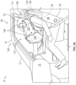
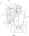
- FIG. 1 is a side view of a portion of an interior of a vehicle 10 equipped with a far-side inflatable airbag assembly 100 according to an embodiment of the present disclosure.
- a dashboard/instrument panel (“dash") 12 is shown for reference, as are a steering wheel 13, a windshield 14, a roof 16 of the vehicle 10, and a far-side door 20.
- the vehicle 10 includes a vehicle occupant position 30 defined by a seat 32 (e.g., a driver seat, a front passenger seat, etc.) and may be a position in which an occupant is generally positioned when seated in a seat of a vehicle.
- a seat 32 e.g., a driver seat, a front passenger seat, etc.
- the vehicle occupant position 30 may be the position in which the vehicle 10 and/or the seat 32 is designed to transport an occupant 50 and/or a position in which an occupant 50 may be seated prior to and/or during a collision event.
- the vehicle occupant position 30 is disposed toward a vehicle 10 left side, and the door 20 is on the vehicle 10 right side, and another vehicle occupant position (not shown, but in many respects similar to the vehicle occupant position 30) may be disposed between the vehicle occupant position 30 and the door 20.
- the illustrated vehicle occupant position 30 of the current embodiment is defined by a driver seat 32.
- the vehicle occupant position 30 is defined by a front passenger seat 32.
- the seat 32 comprises a seat base 34 and a seatback 36.
- the seatback 36 comprises a void 37 configured to receive and support the far-side inflatable airbag assembly 100 of the present disclosure.
- the void 37 may be disposed at an inboard side portion of the seatback 36 and the far-side inflatable airbag assembly 100 may be mounted at least partially within the void 37.
- An occupant 50 is shown seated at the vehicle occupant position 30.
- a head 52, a near-side shoulder 54 (relative to the viewer of FIG. 1 ), and a torso 56 of the occupant 50 are identified for reference.
- the occupant 50 also has a far-side shoulder 55.
- the vehicle occupant position 30 comprises a shoulder portion 38 that may be configured to accommodate a shoulder 54, 55 of an occupant 50 or may otherwise be a position where a shoulder of an occupant 50 may be positioned within the vehicle occupant position 30.
- the occupant 50 may be a driver or a passenger occupant of the vehicle 10.
- an additional vehicle occupant position is disposed between the vehicle occupant position 30 and the door 20.
- the far-side inflatable airbag assembly 100 is disposed within the void 37, and the void 37 is disposed in a portion of the seatback 36 (e.g. a side portion) toward the door 20.
- the void 37 may be disposed in a side portion of the seatback 36 disposed toward a longitudinal centerline of the vehicle and a distance from a laterally adjacent seat or vehicle occupant position of the vehicle to limit inboard lateral displacement of at least a portion of an occupant of the vehicle occupant position during a far-side collision event.
- the far-side inflatable airbag assembly 100 may be a unitized airbag module comprising a housing, an inflator, and an inflatable airbag cushion in a packaged state (see the housing 102, the inflator 104, the inflatable airbag cushion 110 in FIGS. 2A , 2B ).
- the far-side inflatable airbag assembly 100 may comprise individual components, such as the housing 102, the inflator 104, the inflatable airbag cushion 110 in a packaged state, which may be individually installed into the void 37 of the seatback 36 of the vehicle 10.
- the present disclosure anticipates that the far-side inflatable airbag assembly 100 may be installed to the vehicle 10 during or after manufacture of the vehicle 10.
- the void 37 in the seatback 36 is adjacent a support structure of the seatback 36 and disposed inboard (toward the far-side door 20).
- the far-side inflatable airbag assembly 100 may be secured to the support structure to be disposed within the void 37.
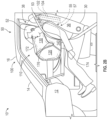
- FIG. 2A is a side view of a portion of the vehicle 10 having the far-side inflatable airbag assembly 100 of FIG. 1 , with the far-side inflatable airbag assembly 100 at least partially deployed.
- the dash 12, the windshield 14, and the roof 16 are shown for reference, as are the vehicle occupant position 30 and the seatback 36.
- the far-side inflatable airbag assembly 100 comprises a housing 102, an inflator 104, and an inflatable airbag cushion 110.
- the inflatable airbag cushion 110 comprises an inflation throat 112, a main cushion 120, a pillow cushion 130, and a sail panel 140.
- the inflation throat 112 comprises a tube or channel connecting the inflatable airbag cushion 110 to the inflator 104.
- the inflation throat 112 is configured to direct inflation gas from the inflator 104 into a void defined by the main cushion 120.
- the pillow cushion 130 also defines a void to receive inflation gas.
- the main cushion 120 and the pillow cushion 130 in a deployed state, each defines a void to receive inflation gas, and the sail panel 140 remains uninflated.
- one or more sensors have identified or otherwise detected a collision event that may be characterized as a far-side collision event, or a far-side oblique collision event, for the vehicle occupant position 30.
- the one or more sensors accordingly have triggered deployment of the far-side inflatable airbag assembly 100.
- Deployment of the far-side inflatable airbag assembly 100 involves activation of the inflator 104, opening of the housing 102, and expansion and disposition of the inflatable airbag cushion 110 adjacent to and inboard of the occupant 50 (between the occupant 50 and the far-side door 20). Initial inflation of the inflatable airbag cushion 110 may force open a closure (not shown) of the housing 102.
- the inflatable airbag cushion 110 is inflated by introduction 106 of inflation gas from the inflator 104 through the inflation throat 112 into the main cushion 120. As the inflatable airbag cushion 110 begins to inflate, it deploys in a forward direction from the void (see the void 37 in FIG. 1 ) at an inboard side portion of the seatback 36 to be positioned adjacent the vehicle occupant position 30 and, more particularly, adjacent the occupant 50. An upper portion of the pillow cushion 130 is coupled to an upper portion of the main cushion 120. As the main cushion 120 inflates, inflation gas from within the void of the main cushion 120 may be introduced 108 from the main cushion 120 into the pillow cushion 130.
- a first end of the sail panel 140 is coupled to a lower portion of the main cushion 120, and a second end of the sail panel 140 is coupled to a lower portion of the pillow cushion 130.
- the pillow cushion 130 and the sail panel 140 may also deploy in a lateral direction.
- the main cushion 120 and the pillow cushion 130 inflate and expand, the sail panel 140 is drawn taught.
- the main cushion 120, the pillow cushion 130, and the sail panel 140 form a shape that may be characterized as roughly triangular or doughnut-like (hereafter, "triangular shape").
- the main cushion 120, the pillow cushion 130, and the sail panel 140 in a deployed state, form the triangular shape in a plane transverse to a longitudinal midline of the vehicle 10.
- the triangular shape enables the main cushion 120, the pillow cushion 130, and the sail panel 140 to mutually support each other and provide resistance to lateral deflection of the inflatable airbag cushion 110.
- FIG. 2B is a side view of a portion of the interior of the vehicle 10 having the far-side inflatable airbag assembly 100 of FIGS. 1 and 2A , with the inflatable airbag cushion 110 in a deployed state (e.g., a substantially inflated state).
- a deployed state e.g., a substantially inflated state
- the triangular shape of the inflatable airbag cushion 110 extends over the far-side shoulder 55 (relative to the perspective of a viewer of FIGS. 2A and 2B ).
- the inflatable airbag cushion 110 may deploy forward into the shoulder portion 38 of the vehicle occupant position 30 that is disposed in the direction of a far-side collision event.
- a first apex 172 of the triangular shape is oriented toward the roof 16, a second apex 174 is oriented downward, and a third apex 176 of the triangular shape is disposed over the far-side shoulder 55 and toward the occupant 50.
- the first apex 172 is formed at a conjunction of the main cushion 120 and the pillow cushion 130.
- the second apex 174 is formed at a conjunction of the main cushion 120 and the sail panel 140.
- the third apex 176 is formed at a conjunction of the pillow cushion 130 and the sail panel 140.
- the sail panel 140 may engage the far-side shoulder 55 of the occupant 50.
- the pillow cushion 130 and the sail panel 140 are configured to extend, in the deployed state, from the main cushion 120 in a direction laterally away from the main cushion 120.
- the apex 176 in a deployed state, extends laterally away from the main cushion 120 and toward the occupant seating position 30.
- the pillow cushion 130 may be configured to receive and support the head 52 of the occupant 50.
- the triangular shape of the inflatable airbag cushion 110 enables the main cushion 120, the pillow cushion 130, and the sail panel 140 to mutually support one another. Furthermore, the triangular shape of the inflatable airbag cushion 110 provides a substantial degree of resistance to deflection.
- the pillow cushion 130 and the sail panel 140 allow, with a relatively small volume of inflation gas, a lateral width of the cushion that can limit deflection and also receive the shoulder 55 and the head 52 of the occupant 50 early on to limit lateral movement of the occupant 50.
- the triangular shape of the inflatable airbag cushion 110 in a deployed state, may resist deflecting in a direction generally toward the far side of the vehicle 10, including oblique deflection.
- the degree of resistance to deflection is a function of a lateral width (or effective lateral width) of the inflatable airbag cushion 110.
- the main cushion 120 and pillow cushion 130 in combination (and as configured by the sail panel) 140 may achieve a lateral width (with respect to a longitudinal axis of the vehicle 10; see e.g., the longitudinal axis 45 in FIG. 6 ) that provides significant support of the occupant 50 during or immediately following a collision event.
- the occupant 50 may receive support of the inflatable airbag cushion 110 before achieving a significant velocity relative to the vehicle 10 (or vehicle moment translation).
- a lower relative velocity of the occupant 50 with respect to the vehicle 10 may enable the inflatable airbag cushion 110 to more effectively retain the occupant 50 within the vehicle occupant position 30.
- a lower relative velocity of the occupant 50 with respect to the vehicle 10 may prevent or mitigate injury to the occupant 50 resulting from the occupant 50 impacting upon internal structures of the vehicle 10.
- the triangular shape of the inflatable airbag cushion 110 in a deployed state allows the pillow cushion 130 to receive and support the head 52 of the occupant 50 while the head 52 and, more particularly, a neck 53 of the occupant 50 are generally aligned with the torso 56 of the occupant 50.
- the triangular shape of the inflatable airbag cushion 110 may allow the sail panel 140 to receive and support the far-side shoulder 55 of the occupant 50 in conjunction with the pillow cushion 130 engaging and supporting the head 52 and the neck 53 of the occupant 50.
- the pillow cushion 130, sail panel 140, and main cushion 120 form a triangular shape configured to engage the occupant 50 earlier in a collision event and thereby reduce lateral movement of the occupant 50.
- this earlier engagement can be accomplished by the pillow cushion 130 and sail panel 140 without a large volume inflation gas requirement.
- Supporting the far-side shoulder 55 of the occupant 50 produces inherent support of the torso 56 of the occupant 50; thus, in a deployed state, the sail panel 140 is configured to limit lateral displacement of the torso 56 of the occupant 50 of the vehicle occupant position 30.
- This conjunctive support of the head 52, the neck 53, and the torso 56 may serve to generally keep a spinal column 57 of the occupant 50 aligned, which, in turn may reduce a likelihood of injury, or degree of injury, to each of the head 52, the neck 53, the far-side shoulder 55, the torso 56, and the spinal column 57 of the occupant 50.
- the apices 172, 174, 176 may permit a degree of articulation of each of the main cushion 120, the pillow cushion 130, and the sail panel 140 while also conveying mutual support between each of these and affording a degree of resistance to deflection of the inflatable airbag cushion 110 away from the occupant 50.
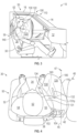
- FIG. 3 is an opposite side view of the portion of the interior of the vehicle 10 having the far-side inflatable airbag assembly 100 of FIGS. 1 and 2A-2B , with the inflatable airbag cushion 110 in a substantially deployed state.
- the dash 12, the windshield 14, the roof 16, and a near-side door 22 of the vehicle 10 are shown for reference, as are the vehicle occupant position 30 and the seatback 36.
- the head 52 and the far-side shoulder 55 (in this view, nearer the viewing plane) of the occupant 50 are shown for reference.
- the main cushion 120 of the inflatable airbag cushion 110 has a generally vertical disposition.
- the pillow cushion 130 and the sail panel 140 are configured to deploy in a direction laterally away from the main cushion 120.
- the pillow cushion 130 is disposed toward the occupant 50 and, more particularly, toward the head 52 of the occupant 50 and at least partially over the far-side shoulder 55.
- the sail panel 140 is disposed toward the occupant 50 and may be engaged against the far-side shoulder 55 of the occupant 50.
- the main cushion 120 is configured with a first coupling 122 (e.g., a tether, or a zero-length tether or other uninflated area).
- the first coupling 122 couples between two panels (see the first and second panels 150, 152 in FIG. 5 ) of the inflatable airbag cushion 110 to reduce a volume of the void defined by the main cushion 120.
- the first coupling 122 may also add a degree of structural support to the main cushion 120, and hence to the inflatable airbag cushion 110. In other words, the first coupling 122 may limit a degree of deformation to which the main cushion 120 may be susceptible by creating an anchor point near a center of the main cushion 120 relative to a perimeter of the main cushion 120.
- the first coupling 122 may reduce a total volume of inflation gas required to inflate the inflatable airbag cushion 110, which may result in a reduction in timing between initiation of deployment and achievement of substantial deployment.
- a reduction in total volume of inflation gas required to inflate the inflatable airbag cushion 110 may permit use of a smaller inflator 104, resulting in a more compact far-side inflatable airbag assembly 100.
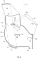
- FIG 4 is a plan view of the vehicle occupant position 30 of the vehicle 10 having the far-side inflatable airbag assembly 100 of FIGS. 1-3 , with the inflatable airbag cushion 110 in a deployed state.
- a logical midline 45 of the vehicle (see the vehicle in FIGS. 1-3 ) with a vehicle forward direction 47 indicated.
- the inflatable airbag cushion 110 is substantially inflated.
- the occupant 50 is seated in an upright posture on the seat base 34 and against the seatback 36.
- the main cushion 120 is disposed generally vertically and inboard of the occupant 50.
- a rear aspect of the main cushion 120 may extend generally upward and forward from the inflator 104, with a forward aspect of the main cushion 120 angled somewhat toward the vehicle occupant position 30.
- the second coupling 132 reduces a total volume of inflation gas required to inflate the inflatable airbag cushion 110.
- the second coupling 132 also configures the inflatable airbag cushion 110 to form the first apex (see the first apex 172 in FIG. 2B ) to dispose the pillow cushion 130 toward the head 52 of the occupant 50 and the third apex (see the third apex 176 in FIG. 2B ) over the far-side shoulder 55 of the occupant 50.
- the second coupling 132 further configures the inflatable airbag cushion 110 to direct inflation gas from the main cushion 120 to the pillow cushion 130. ( FIG. 2A described above illustrates inflation gas being introduced 108 from the main cushion 120 into the pillow cushion 130.)
- the pillow cushion 130 of FIG. 4 has a panel 131 disposed toward the vehicle occupant position 30, the panel 131 having a curved profile, which curves disposed toward the occupant 50 at a forward end.
- the curved profile is configured to receive the head 52 of the occupant 50 to prevent or reduce injury to the head 52 by limiting one or more of forward movement of the head 52, lateral movement of the head 52, oblique movement of the head 52, and rotation of the head 52.
- the main cushion 120 and the pillow cushion 130 form the first apex 172 of the triangular shape at a second coupling 132.
- a lower aspect of the main cushion 120 couples to a lower aspect of the sail panel 140 to form the second apex 174.
- a lower aspect of the pillow cushion 130 couples to an upper aspect of the sail panel 140 to form the third apex 176.
- the sail panel 140 is configured to engage the far-side shoulder 55 of the occupant 50.
- the sail panel 140 and the pillow cushion 130 engage, respectively, the far-side shoulder 55 and the head 52 of the occupant 50 to support the head 52, the far-side shoulder 55, the torso 56, and the neck 53 of the occupant 50 during a far-side collision event or a far-side oblique collision event.
- the inflatable airbag cushion 110 thus configured may prevent or reduce a degree of injury to the occupant 50 in a far-side collision event or a far-side oblique collision event. More particularly, in the illustration of FIG.
- a far-side collision event or a far-side oblique collision event would occur to the reader's right, with the energies of the collision tending to push the vehicle occupant position 30 toward the left, resulting in a tendency of the occupant 50 to be displaced in a rightward relative direction.
- the occupant 50 may be effectively retained at the vehicle occupant position 30 with relatively gradual dissipation of the energies tending to displace the occupant 50 in a right or right-lateral direction.
- a second vehicle occupant position 40 in many aspects similar to the vehicle occupant position 30 may be disposed to the immediate right of the vehicle occupant position 30.
- the inflatable airbag cushion 110 may prevent a tendency of the collision energies to displace the occupant 50 into, onto, or past an adjacent vehicle occupant position 40. If the adjacent vehicle occupant position is also occupied, the inflatable airbag cushion 110 may protect the occupant of the adjacent vehicle occupant position and the occupant 50 of the vehicle occupant position 30 from injuries that otherwise may result from occupant-to-occupant intravehicle collision.
- each seat 32, 42, etc. may be equipped with a far-side inflatable airbag assembly 100 at either side of each seat disposed adjacent another seat.
- Each far-side inflatable airbag assembly 100 may be configured to deploy only when the particular vehicle occupant position 30, 40, etc., is occupied, and only when the particular far-side inflatable airbag assembly 100 is deployable between the respective occupied vehicle occupant position 30, 40, etc., and a far-side collision event.
- a right-side-disposed far-side inflatable airbag assembly 100 mounted at an occupied vehicle occupant position 30, 40, etc. may deploy, and a left-side-disposed far-side inflatable airbag assembly 100 may remain undeployed.
- FIG. 5 is a plan view of the inflatable airbag cushion 110 of the inflatable airbag assembly 100 of FIGS. 1-4 in a preinstallation state.
- the inflatable airbag cushion 110 comprises a first panel 150 and a second panel 152, with the first panel 150, in the present view, overlying the second panel 152.
- the first panel 150 and the second panel 152 are coupled together at a perimeter coupling 154.
- the first panel 150 comprises at least a first side of the main cushion 120 and the pillow cushion 130.
- the second panel 152 comprises at least a second side of the main cushion 120 and the pillow cushion 130.
- the first panel 150 may further comprise the sail panel 140.
- the second panel 152 may further comprise the sail panel 140.
- the perimeter coupling 154 circumscribes and couples together a portion of the inflatable airbag cushion 110 defining a perimeter of the main cushion 120 and the pillow cushion 130, and defining the voids of the main cushion 120 and the pillow cushion 130 to receive inflation gas.
- the first panel 150 and the second panel 152 are further coupled together at the first coupling 122 and at the second coupling 132.
- the first and second couplings 122, 132 reduce a total volume of inflation gas needed to inflate the inflatable airbag cushion 110.
- the first and second couplings 122, 132 may provide structural support to the main cushion 120 and the pillow cushion 130 in a deployed state.
- the inflatable airbag cushion 110 comprises a sail panel first tab 142 and a sail panel second tab 144.
- the first tab 142 and the second tab 144 are coupled together. Coupling together the first tab 142 and the second tab 144 configures the inflatable airbag cushion 110 to form the roughly triangular or doughnut-like shape when deployed during a collision event.
- the second coupling 132 assists in disposing the pillow cushion 130 laterally toward the occupant (see the occupant 50 in FIGS. 2A-4 ) and forming the first apex 172.
- the coupling of the first and second tabs 142, 144 forms the second apex 174.
- the coupling together of the first and second tabs 142, 144 is illustrated by a pair of dash-dot lines drawn between the first and second tabs 142, 144.
- a portion of the perimeter coupling 154 enables the inflatable airbag cushion 110 to form the third apex 176.
- the perimeter coupling 154 excludes a portion of the first and second panels 150, 152 to form the inflation throat 112.
- the inflation throat 112 may be coupled to the inflator (see the inflator 104 in FIG. 2A ).
- the perimeter coupling 154, the first coupling 122, the second coupling 132, and the coupling of the first and second tabs 142, 144 may be accomplished by one or more of sewing, radio frequency welding, adhesive, or any other appropriate means.
- the inflatable airbag cushion 110 further comprises a tether 160.
- the tether 160 has a first end 162a and a second end 166a.
- the first end 162a of the tether 160 may be coupled 164 near or at the second coupling 132 of the inflatable airbag cushion 110.
- a first end 162b is shown coupled at the second coupling 132, for reference.
- the second end 166a of the tether 160 may be coupled at a portion 168 of the perimeter coupling 154.
- a second end 166b is shown coupled at the portion 168 of the perimeter coupling 154.
- the tether 160 may assist in disposing the inflatable airbag cushion 110 as described at FIGS. 2A-4 .
- FIG. 6 is a front view of the inflatable airbag cushion 110 of the far-side inflatable airbag assembly 100 of FIGS. 1-5 in a deployed state and receiving an occupant 50 seated in the vehicle occupant position 30.
- the inflatable airbag cushion 110 is shown substantially inflated.
- the main cushion 120, the pillow cushion 130, and the sail panel 140 are shown, as are the first and second couplings 122, 132.
- a seat back 36 of the vehicle occupant position 30 is also shown for reference.
- An occupant 50 is shown seated at the vehicle occupant position 30.
- the sail panel 140 has engaged or received the far-side shoulder 55 of the occupant 50.
- the vehicle logical midline 45 is shown, for ease of reference, as a vertical plane in line with a front-to-rear axis of the vehicle.
- the inflatable airbag cushion 110 deploys in a direction transverse 49 to the vehicle logical midline 45.
- the roughly triangular shape 170 formed by the deployed inflatable airbag cushion 110 is shown, as are the first, second and third apices 172, 174, 176 of the roughly triangular shape 170.
- the illustrated triangular shape 170 is a generalization and not intended to depict an exact form of the inflatable airbag cushion 110.
- the apices 172, 174, 176 may, in some embodiments be more rounded that in the embodiment of the inflatable airbag cushion 110 shown in FIG. 6 ; hence, the shape may be roughly doughnut-like 178.
- the particular orientation of the roughly triangular shape 170 and the disposition of the apices 172, 174, 176 may vary.
- Coupled to refers to any form of interaction between two or more entities, including mechanical, electrical, magnetic, electromagnetic, fluid, and thermal interaction. Two components may be coupled to each other even though they are not in direct contact with each other.
- vehicle occupant position refers to a position in which an occupant is generally positioned when seated in a seat of a vehicle or typically expected to be positioned during vehicle operation.
- occupant refers to a person or crash test dummy within a vehicle.
Landscapes
- Engineering & Computer Science (AREA)
- Mechanical Engineering (AREA)
- Air Bags (AREA)
Claims (11)
- Aufblasbares Airbagsystem (100), umfassend:einen Gasgenerator (104); undein aufblasbares Airbagkissen (110), das konfiguriert ist, um an einem Seitenteil eines Sitzes (32) eines Fahrzeugs (10) montiert zu werden und sich in einer Vorwärtsrichtung von dem Seitenteil des Sitzes (32) zu entfalten, um angrenzend an eine Fahrzeuginsassenposition (30) positioniert zu werden, die durch den Sitz (32) definiert ist, und wobei das aufblasbare Airbagkissen (110) umfasst:ein Hauptkissen, das mit dem Gasgenerator (104) gekoppelt ist (120), um sich von dem Abschnitt des Sitzes (32) nach vorne zu entfalten;ein Kopfkissen, das an einem oberen Abschnitt mit einem oberen Abschnitt des Hauptkissens (120) gekoppelt ist (130), um auf einer Insassenseite des Hauptkissens (120) angeordnet zu werden und zwischen dem Hauptkissen (120) und der Fahrzeuginsassenposition (30) positioniert zu werden; undeine Segelbahn, die an einem ersten Ende mit einem unteren Abschnitt des Hauptkissens (120) und an einem zweiten Ende mit einem unteren Abschnitt des Kopfkissens (130) gekoppelt ist (140),wobei das Hauptkissen (120) und das Kopfkissen (130) aus einer ersten Bahn (150) und einer zweiten Bahn (152) ausgebildet sind, die an einer Umfangskopplung (154) derart miteinander gekoppelt sind, dass eine erste Seite der ersten Bahn (150) mindestens eine erste Seite des Hauptkissens (120) und des Kopfkissens (130) umfasst und die zweite Bahn (152) mindestens eine zweite Seite des Hauptkissens (120) und des Kopfkissens (130) umfasst,wobei das Hauptkissen (120), das Kopfkissen (130) und die Segelbahn (140) in einem entfalteten Zustand eine Form (170) ausbilden, die etwa dreieckig ist, wobei sich die Form über eine Schulter (55) eines Insassen (50) erstreckt,wobei: eine erste Spitze (172) der dreieckigen Form, die an einer Verbindung des Hauptkissens (120) und des Kopfkissens (130) ausgebildet ist, in Richtung eines Dachs (16) des Fahrzeugs (10) gerichtet ist; eine zweite Spitze (174) der dreieckigen Form, die an einer Verbindung des Hauptkissens (120) und der Segelbahn (140) ausgebildet ist, nach unten gerichtet ist; und eine dritte Spitze (176) der dreieckigen Form, die an einer Verbindung des Kopfkissens (130) und der Segelbahn (140) ausgebildet ist, unterhalb der ersten Spitze (172) über der abgewandten Schulter (55) und in Richtung des Insassen (50) angeordnet ist;dadurch gekennzeichnet, dass das Hauptkissen (120) und das Kopfkissen (130) an einer Kopplung (132) die erste Spitze (172) ausbilden,wobei die Kopplung (132) zwischen der ersten Bahn (150) und der zweiten Bahn (152) eine Kopplung herstellt und das aufblasbare Airbagkissen (110) konfiguriert, um die erste Spitze (172) auszubilden, um das Kopfkissen (130) in Richtung der dritten Spitze (176) anzuordnen.
- Aufblasbares Airbagsystem (100) nach Anspruch 1, wobei das Hauptkissen (120) und das Kopfkissen (130) in einem entfalteten Zustand jeweils einen Hohlraum definieren, um Füllgas aufzunehmen, und die Segelbahn (140) unentfaltet bleibt.
- Aufblasbares Airbagsystem (100) nach einem der Ansprüche 1 und 2, wobei der Seitenteil des Sitzes (32) ein Innenteil ist, der in Richtung einer Längsmittellinie (45) des Fahrzeugs (10) und in einem Abstand von einem seitlich angrenzenden Sitz (40) des Fahrzeugs (10) angeordnet ist, um eine seitliche Innenverschiebung von mindestens einem Teil eines Insassen (50) der Fahrzeuginsassenposition (30) während eines Aufprallereignisses auf der abgewandten Seite zu begrenzen.
- Aufblasbares Airbagsystem (100) nach einem der Ansprüche 1 bis 3, wobei ein Hohlraum, der durch das Kopfkissen (130) definiert ist, in Fluidkommunikation mit einem Hohlraum steht, der durch das Hauptkissen (120) definiert ist, um Füllgas von dem Hauptkissen (120) aufzunehmen.
- Aufblasbares Airbagsystem (100) nach einem der Ansprüche 1 bis 4, wobei das Kopfkissen (130) und die Segelbahn (140) in einem entfalteten Zustand konfiguriert sind, um sich von dem Hauptkissen (120) in eine Richtung seitlich weg von dem Hauptkissen (120) und über einen Schulterteil (38) der Fahrzeuginsassenposition (30) zu erstrecken, um positioniert zu sein, um einen Kopf (52) eines Insassen (50) der Fahrzeuginsassenposition (30) während eines Aufprallereignisses abzufedern und seitlichen Halt bereitzustellen.
- Aufblasbares Airbagsystem (100) nach einem der Ansprüche 1 bis 5, wobei die Segelbahn (140) in einem entfalteten Zustand konfiguriert ist, um mit einer Schulter (55) eines Insassen (50) der Fahrzeuginsassenposition (30) in Eingriff zu kommen.
- Aufblasbares Airbagsystem (100) nach einem der Ansprüche 1 bis 6, wobei das Hauptkissen (120), das Kopfkissen (130) und die Segelbahn (140) sich aufgrund der Form (170, 178) gegenseitig halten, die sie ausbilden, um Widerstand gegenüber einer Verformung des aufblasbaren Airbagkissens (110) bereitzustellen.
- Aufblasbares Airbagsystem (100) nach einem der Ansprüche 1 bis 7, wobei das Kopfkissen (130) in einem entfalteten Zustand strukturellen Halt von dem Hauptkissen (120) aufnimmt.
- Aufblasbares Airbagsystem (100) nach einem der Ansprüche 1 bis 8, wobei die Segelbahn (140) in einem entfalteten Zustand angrenzend an die Fahrzeuginsassenposition (30) positioniert ist, um die seitliche Verschiebung einer Schulter (55) eines Insassen (50) der Fahrzeuginsassenposition (30) zu begrenzen.
- Aufblasbares Airbagsystem (100) nach einem der Ansprüche 1 bis 9, wobei das Kopfkissen (130) in einem entfalteten Zustand konfiguriert ist, um die seitliche Verschiebung eines Kopfes (52) eines Insassen (50) der Fahrzeuginsassenposition (30) zu begrenzen.
- Aufblasbares Airbagsystem (100) nach einem der Ansprüche 1 bis 10, wobei das Kopfkissen (120) in einem entfalteten Zustand eine Bahn (131) umfasst, die in Richtung der Fahrzeuginsassenposition (30) angeordnet ist, wobei die Bahn (131) ein gekrümmtes Profil (131p) aufweist, das konfiguriert ist, um eine Vorwärtsbewegung eines Kopfes (52) eines Insassen (50) der Fahrzeuginsassenposition (30) zu begrenzen.
Applications Claiming Priority (2)
| Application Number | Priority Date | Filing Date | Title |
|---|---|---|---|
| US17/115,175 US11577681B2 (en) | 2020-12-08 | 2020-12-08 | Far-side airbag assemblies with pillow and sail |
| PCT/US2021/072190 WO2022126051A1 (en) | 2020-12-08 | 2021-11-02 | Far-side airbag assemblies with pillow and sail |
Publications (2)
| Publication Number | Publication Date |
|---|---|
| EP4259491A1 EP4259491A1 (de) | 2023-10-18 |
| EP4259491B1 true EP4259491B1 (de) | 2025-05-28 |
Family
ID=78806754
Family Applications (1)
| Application Number | Title | Priority Date | Filing Date |
|---|---|---|---|
| EP21815858.2A Active EP4259491B1 (de) | 2020-12-08 | 2021-11-02 | Seitenairbag-baugruppen mit kissen und segel |
Country Status (4)
| Country | Link |
|---|---|
| US (1) | US11577681B2 (de) |
| EP (1) | EP4259491B1 (de) |
| JP (1) | JP2023553789A (de) |
| WO (1) | WO2022126051A1 (de) |
Families Citing this family (2)
| Publication number | Priority date | Publication date | Assignee | Title |
|---|---|---|---|---|
| KR20240175023A (ko) * | 2023-06-12 | 2024-12-19 | 현대모비스 주식회사 | 차량용 에어백 |
| DE102024106920B4 (de) * | 2024-03-11 | 2026-03-05 | Autoliv Development Ab | Seitenairbag für ein Fahrzeug |
Family Cites Families (25)
| Publication number | Priority date | Publication date | Assignee | Title |
|---|---|---|---|---|
| US5730464A (en) | 1995-08-11 | 1998-03-24 | General Motors Corporation | Air bag module with tether |
| US5636862A (en) * | 1995-09-07 | 1997-06-10 | General Motors Corporation | Air bag assembly with tether |
| US7549672B2 (en) * | 2004-05-27 | 2009-06-23 | Toyoda Gosei Co., Ltd. | Side airbag device |
| US7240915B2 (en) * | 2004-12-03 | 2007-07-10 | Ford Global Technologies, Llc | Vehicle seating system with airbag-based occupant reaction surface |
| US20060119083A1 (en) * | 2004-12-03 | 2006-06-08 | Ford Motor Company | Seating system for automotive vehicle |
| KR101720983B1 (ko) * | 2011-04-18 | 2017-03-29 | 현대모비스 주식회사 | 사이드 에어백 장치 |
| JP5754436B2 (ja) * | 2012-12-03 | 2015-07-29 | トヨタ自動車株式会社 | 車両用乗員拘束システム |
| JP6203402B2 (ja) * | 2014-06-24 | 2017-09-27 | オートリブ ディベロップメント エービー | サイドエアバッグ装置 |
| WO2016039160A1 (ja) * | 2014-09-08 | 2016-03-17 | オートリブ ディベロップメント エービー | 乗員拘束装置 |
| US9994181B1 (en) * | 2017-03-31 | 2018-06-12 | Ford Global Technologies, Llc | Vehicle seat including airbag |
| JP6880954B2 (ja) * | 2017-04-07 | 2021-06-02 | トヨタ自動車株式会社 | 車両用サイドエアバッグ装置及びその製造方法 |
| US10336278B2 (en) * | 2017-07-14 | 2019-07-02 | Autoliv Asp, Inc. | Inflatable airbag harness assemblies |
| KR102452467B1 (ko) * | 2017-08-24 | 2022-10-11 | 현대자동차주식회사 | 차량용 에어백 |
| KR102399622B1 (ko) | 2017-08-24 | 2022-05-17 | 현대자동차주식회사 | 차량의 사이드 에어백 장치 |
| KR102332056B1 (ko) * | 2017-09-27 | 2021-11-29 | 현대모비스 주식회사 | 사이드 에어백 장치 |
| DE102018103071B4 (de) * | 2017-11-15 | 2024-03-07 | Joyson Safety Systems Germany Gmbh | Gassack für ein Fahrzeuginsassen-Rückhaltesystem eines Kraftfahrzeugs |
| DE102018120880A1 (de) * | 2017-12-08 | 2019-06-13 | Trw Automotive Gmbh | Seitengassack und Fahrzeuginsassen-Rückhaltesystem mit einem Seitengassack |
| DE102018101395A1 (de) * | 2018-01-23 | 2019-07-25 | Trw Automotive Gmbh | Seitengassack und Fahrzeuginsassen-Rückhaltesystem |
| JP6915561B2 (ja) * | 2018-02-14 | 2021-08-04 | 豊田合成株式会社 | ファーサイドエアバッグ装置 |
| EP3778310B1 (de) * | 2018-04-05 | 2022-07-13 | Autoliv Development AB | Seitenairbagvorrichtung |
| DE102018108171A1 (de) * | 2018-04-06 | 2019-10-10 | Trw Automotive Gmbh | Fahrzeuginsassen-Rückhaltesystem mit einem Seitengassack |
| DE102018114771B4 (de) * | 2018-06-20 | 2020-07-09 | Isi Automotive Holding Gmbh | Rückhaltevorrichtung zur Reduzierung einer schlagartigen Seitwärts- als auch Vorwärtsbewegung eines Insassen |
| DE102018214536B4 (de) | 2018-08-28 | 2024-03-07 | Joyson Safety Systems Germany Gmbh | Gassackanordnung für ein Fahrzeuginsassen-Rückhaltesystem eines Kraftfahrzeugs |
| US10960841B2 (en) * | 2019-04-10 | 2021-03-30 | Ford Global Technologies, Llc | Seat airbag |
| WO2020255817A1 (ja) * | 2019-06-20 | 2020-12-24 | 芦森工業株式会社 | サイドエアバッグ装置 |
-
2020
- 2020-12-08 US US17/115,175 patent/US11577681B2/en active Active
-
2021
- 2021-11-02 JP JP2023528116A patent/JP2023553789A/ja active Pending
- 2021-11-02 EP EP21815858.2A patent/EP4259491B1/de active Active
- 2021-11-02 WO PCT/US2021/072190 patent/WO2022126051A1/en not_active Ceased
Also Published As
| Publication number | Publication date |
|---|---|
| US11577681B2 (en) | 2023-02-14 |
| CN116472205A (zh) | 2023-07-21 |
| WO2022126051A1 (en) | 2022-06-16 |
| US20220176904A1 (en) | 2022-06-09 |
| EP4259491A1 (de) | 2023-10-18 |
| JP2023553789A (ja) | 2023-12-26 |
Similar Documents
| Publication | Publication Date | Title |
|---|---|---|
| US10266145B2 (en) | Frontal airbag assemblies | |
| US10336278B2 (en) | Inflatable airbag harness assemblies | |
| US10246043B2 (en) | Overhead airbag assemblies | |
| US9676355B2 (en) | Frontal airbag systems for oblique crash protection | |
| US10183645B2 (en) | Frontal airbag systems for oblique impact | |
| US10293777B2 (en) | Multi-cushion airbag assemblies for reducing rotational velocity of an occupant's head | |
| US9771047B2 (en) | Frontal airbag systems for oblique crash protection | |
| EP4090559B1 (de) | Fahrzeug mit einem sitz und einer airbaganordnung | |
| US6966579B2 (en) | Extensible tethered airbag system | |
| EP3802231B1 (de) | Seitenairbaganordnung | |
| US9272681B1 (en) | Knee airbag deployable from a side panel | |
| EP4259491B1 (de) | Seitenairbag-baugruppen mit kissen und segel | |
| EP3959105B1 (de) | Seitenairbaganordnung | |
| US11292423B2 (en) | Vent flap for airbag assemblies | |
| US11027688B2 (en) | Systems and methods to support an inflatable airbag cushion | |
| CN116472205B (zh) | 具有枕和帆的远侧安全气囊组件 |
Legal Events
| Date | Code | Title | Description |
|---|---|---|---|
| STAA | Information on the status of an ep patent application or granted ep patent |
Free format text: STATUS: UNKNOWN |
|
| STAA | Information on the status of an ep patent application or granted ep patent |
Free format text: STATUS: THE INTERNATIONAL PUBLICATION HAS BEEN MADE |
|
| PUAI | Public reference made under article 153(3) epc to a published international application that has entered the european phase |
Free format text: ORIGINAL CODE: 0009012 |
|
| STAA | Information on the status of an ep patent application or granted ep patent |
Free format text: STATUS: REQUEST FOR EXAMINATION WAS MADE |
|
| 17P | Request for examination filed |
Effective date: 20230630 |
|
| AK | Designated contracting states |
Kind code of ref document: A1 Designated state(s): AL AT BE BG CH CY CZ DE DK EE ES FI FR GB GR HR HU IE IS IT LI LT LU LV MC MK MT NL NO PL PT RO RS SE SI SK SM TR |
|
| DAV | Request for validation of the european patent (deleted) | ||
| DAX | Request for extension of the european patent (deleted) | ||
| GRAP | Despatch of communication of intention to grant a patent |
Free format text: ORIGINAL CODE: EPIDOSNIGR1 |
|
| STAA | Information on the status of an ep patent application or granted ep patent |
Free format text: STATUS: GRANT OF PATENT IS INTENDED |
|
| INTG | Intention to grant announced |
Effective date: 20250102 |
|
| GRAS | Grant fee paid |
Free format text: ORIGINAL CODE: EPIDOSNIGR3 |
|
| GRAA | (expected) grant |
Free format text: ORIGINAL CODE: 0009210 |
|
| STAA | Information on the status of an ep patent application or granted ep patent |
Free format text: STATUS: THE PATENT HAS BEEN GRANTED |
|
| AK | Designated contracting states |
Kind code of ref document: B1 Designated state(s): AL AT BE BG CH CY CZ DE DK EE ES FI FR GB GR HR HU IE IS IT LI LT LU LV MC MK MT NL NO PL PT RO RS SE SI SK SM TR |
|
| REG | Reference to a national code |
Ref country code: GB Ref legal event code: FG4D |
|
| REG | Reference to a national code |
Ref country code: CH Ref legal event code: EP |
|
| REG | Reference to a national code |
Ref country code: DE Ref legal event code: R096 Ref document number: 602021031492 Country of ref document: DE |
|
| REG | Reference to a national code |
Ref country code: IE Ref legal event code: FG4D |
|
| REG | Reference to a national code |
Ref country code: NL Ref legal event code: MP Effective date: 20250528 |
|
| PG25 | Lapsed in a contracting state [announced via postgrant information from national office to epo] |
Ref country code: ES Free format text: LAPSE BECAUSE OF FAILURE TO SUBMIT A TRANSLATION OF THE DESCRIPTION OR TO PAY THE FEE WITHIN THE PRESCRIBED TIME-LIMIT Effective date: 20250528 Ref country code: FI Free format text: LAPSE BECAUSE OF FAILURE TO SUBMIT A TRANSLATION OF THE DESCRIPTION OR TO PAY THE FEE WITHIN THE PRESCRIBED TIME-LIMIT Effective date: 20250528 |
|
| REG | Reference to a national code |
Ref country code: LT Ref legal event code: MG9D |
|
| PG25 | Lapsed in a contracting state [announced via postgrant information from national office to epo] |
Ref country code: GR Free format text: LAPSE BECAUSE OF FAILURE TO SUBMIT A TRANSLATION OF THE DESCRIPTION OR TO PAY THE FEE WITHIN THE PRESCRIBED TIME-LIMIT Effective date: 20250829 Ref country code: NO Free format text: LAPSE BECAUSE OF FAILURE TO SUBMIT A TRANSLATION OF THE DESCRIPTION OR TO PAY THE FEE WITHIN THE PRESCRIBED TIME-LIMIT Effective date: 20250828 |
|
| PG25 | Lapsed in a contracting state [announced via postgrant information from national office to epo] |
Ref country code: PL Free format text: LAPSE BECAUSE OF FAILURE TO SUBMIT A TRANSLATION OF THE DESCRIPTION OR TO PAY THE FEE WITHIN THE PRESCRIBED TIME-LIMIT Effective date: 20250528 Ref country code: NL Free format text: LAPSE BECAUSE OF FAILURE TO SUBMIT A TRANSLATION OF THE DESCRIPTION OR TO PAY THE FEE WITHIN THE PRESCRIBED TIME-LIMIT Effective date: 20250528 |
|
| PG25 | Lapsed in a contracting state [announced via postgrant information from national office to epo] |
Ref country code: BG Free format text: LAPSE BECAUSE OF FAILURE TO SUBMIT A TRANSLATION OF THE DESCRIPTION OR TO PAY THE FEE WITHIN THE PRESCRIBED TIME-LIMIT Effective date: 20250528 |
|
| PG25 | Lapsed in a contracting state [announced via postgrant information from national office to epo] |
Ref country code: HR Free format text: LAPSE BECAUSE OF FAILURE TO SUBMIT A TRANSLATION OF THE DESCRIPTION OR TO PAY THE FEE WITHIN THE PRESCRIBED TIME-LIMIT Effective date: 20250528 |
|
| PG25 | Lapsed in a contracting state [announced via postgrant information from national office to epo] |
Ref country code: RS Free format text: LAPSE BECAUSE OF FAILURE TO SUBMIT A TRANSLATION OF THE DESCRIPTION OR TO PAY THE FEE WITHIN THE PRESCRIBED TIME-LIMIT Effective date: 20250828 |
|
| PG25 | Lapsed in a contracting state [announced via postgrant information from national office to epo] |
Ref country code: IS Free format text: LAPSE BECAUSE OF FAILURE TO SUBMIT A TRANSLATION OF THE DESCRIPTION OR TO PAY THE FEE WITHIN THE PRESCRIBED TIME-LIMIT Effective date: 20250928 |
|
| PG25 | Lapsed in a contracting state [announced via postgrant information from national office to epo] |
Ref country code: LV Free format text: LAPSE BECAUSE OF FAILURE TO SUBMIT A TRANSLATION OF THE DESCRIPTION OR TO PAY THE FEE WITHIN THE PRESCRIBED TIME-LIMIT Effective date: 20250528 |
|
| REG | Reference to a national code |
Ref country code: AT Ref legal event code: MK05 Ref document number: 1798472 Country of ref document: AT Kind code of ref document: T Effective date: 20250528 |
|
| PGFP | Annual fee paid to national office [announced via postgrant information from national office to epo] |
Ref country code: DE Payment date: 20251126 Year of fee payment: 5 |
|
| PGFP | Annual fee paid to national office [announced via postgrant information from national office to epo] |
Ref country code: GB Payment date: 20251125 Year of fee payment: 5 |
|
| PG25 | Lapsed in a contracting state [announced via postgrant information from national office to epo] |
Ref country code: SM Free format text: LAPSE BECAUSE OF FAILURE TO SUBMIT A TRANSLATION OF THE DESCRIPTION OR TO PAY THE FEE WITHIN THE PRESCRIBED TIME-LIMIT Effective date: 20250528 Ref country code: DK Free format text: LAPSE BECAUSE OF FAILURE TO SUBMIT A TRANSLATION OF THE DESCRIPTION OR TO PAY THE FEE WITHIN THE PRESCRIBED TIME-LIMIT Effective date: 20250528 Ref country code: AT Free format text: LAPSE BECAUSE OF FAILURE TO SUBMIT A TRANSLATION OF THE DESCRIPTION OR TO PAY THE FEE WITHIN THE PRESCRIBED TIME-LIMIT Effective date: 20250528 |
|
| PGFP | Annual fee paid to national office [announced via postgrant information from national office to epo] |
Ref country code: FR Payment date: 20251124 Year of fee payment: 5 |
|
| PG25 | Lapsed in a contracting state [announced via postgrant information from national office to epo] |
Ref country code: CZ Free format text: LAPSE BECAUSE OF FAILURE TO SUBMIT A TRANSLATION OF THE DESCRIPTION OR TO PAY THE FEE WITHIN THE PRESCRIBED TIME-LIMIT Effective date: 20250528 |
|
| PG25 | Lapsed in a contracting state [announced via postgrant information from national office to epo] |
Ref country code: EE Free format text: LAPSE BECAUSE OF FAILURE TO SUBMIT A TRANSLATION OF THE DESCRIPTION OR TO PAY THE FEE WITHIN THE PRESCRIBED TIME-LIMIT Effective date: 20250528 |
|
| PG25 | Lapsed in a contracting state [announced via postgrant information from national office to epo] |
Ref country code: SK Free format text: LAPSE BECAUSE OF FAILURE TO SUBMIT A TRANSLATION OF THE DESCRIPTION OR TO PAY THE FEE WITHIN THE PRESCRIBED TIME-LIMIT Effective date: 20250528 |
|
| PG25 | Lapsed in a contracting state [announced via postgrant information from national office to epo] |
Ref country code: IT Free format text: LAPSE BECAUSE OF FAILURE TO SUBMIT A TRANSLATION OF THE DESCRIPTION OR TO PAY THE FEE WITHIN THE PRESCRIBED TIME-LIMIT Effective date: 20250528 |
|
| PG25 | Lapsed in a contracting state [announced via postgrant information from national office to epo] |
Ref country code: RO Free format text: LAPSE BECAUSE OF FAILURE TO SUBMIT A TRANSLATION OF THE DESCRIPTION OR TO PAY THE FEE WITHIN THE PRESCRIBED TIME-LIMIT Effective date: 20250528 |