EP4087692B1 - Method and apparatus for producing flat metal products - Google Patents
Method and apparatus for producing flat metal products Download PDFInfo
- Publication number
- EP4087692B1 EP4087692B1 EP20829688.9A EP20829688A EP4087692B1 EP 4087692 B1 EP4087692 B1 EP 4087692B1 EP 20829688 A EP20829688 A EP 20829688A EP 4087692 B1 EP4087692 B1 EP 4087692B1
- Authority
- EP
- European Patent Office
- Prior art keywords
- stand
- stands
- rolling
- thickness
- change
- Prior art date
- Legal status (The legal status is an assumption and is not a legal conclusion. Google has not performed a legal analysis and makes no representation as to the accuracy of the status listed.)
- Active
Links
Images


Classifications
-
- B—PERFORMING OPERATIONS; TRANSPORTING
- B21—MECHANICAL METAL-WORKING WITHOUT ESSENTIALLY REMOVING MATERIAL; PUNCHING METAL
- B21B—ROLLING OF METAL
- B21B1/00—Metal-rolling methods or mills for making semi-finished products of solid or profiled cross-section; Sequence of operations in milling trains; Layout of rolling-mill plant, e.g. grouping of stands; Succession of passes or of sectional pass alternations
- B21B1/46—Metal-rolling methods or mills for making semi-finished products of solid or profiled cross-section; Sequence of operations in milling trains; Layout of rolling-mill plant, e.g. grouping of stands; Succession of passes or of sectional pass alternations for rolling metal immediately subsequent to continuous casting
- B21B1/463—Metal-rolling methods or mills for making semi-finished products of solid or profiled cross-section; Sequence of operations in milling trains; Layout of rolling-mill plant, e.g. grouping of stands; Succession of passes or of sectional pass alternations for rolling metal immediately subsequent to continuous casting in a continuous process, i.e. the cast not being cut before rolling
-
- B—PERFORMING OPERATIONS; TRANSPORTING
- B21—MECHANICAL METAL-WORKING WITHOUT ESSENTIALLY REMOVING MATERIAL; PUNCHING METAL
- B21B—ROLLING OF METAL
- B21B37/00—Control devices or methods specially adapted for metal-rolling mills or the work produced thereby
- B21B37/16—Control of thickness, width, diameter or other transverse dimensions
- B21B37/24—Automatic variation of thickness according to a predetermined program
- B21B37/26—Automatic variation of thickness according to a predetermined program for obtaining one strip having successive lengths of different constant thickness
-
- B—PERFORMING OPERATIONS; TRANSPORTING
- B21—MECHANICAL METAL-WORKING WITHOUT ESSENTIALLY REMOVING MATERIAL; PUNCHING METAL
- B21B—ROLLING OF METAL
- B21B1/00—Metal-rolling methods or mills for making semi-finished products of solid or profiled cross-section; Sequence of operations in milling trains; Layout of rolling-mill plant, e.g. grouping of stands; Succession of passes or of sectional pass alternations
- B21B1/22—Metal-rolling methods or mills for making semi-finished products of solid or profiled cross-section; Sequence of operations in milling trains; Layout of rolling-mill plant, e.g. grouping of stands; Succession of passes or of sectional pass alternations for rolling plates, strips, bands or sheets of indefinite length
- B21B1/24—Metal-rolling methods or mills for making semi-finished products of solid or profiled cross-section; Sequence of operations in milling trains; Layout of rolling-mill plant, e.g. grouping of stands; Succession of passes or of sectional pass alternations for rolling plates, strips, bands or sheets of indefinite length in a continuous or semi-continuous process
-
- B—PERFORMING OPERATIONS; TRANSPORTING
- B21—MECHANICAL METAL-WORKING WITHOUT ESSENTIALLY REMOVING MATERIAL; PUNCHING METAL
- B21B—ROLLING OF METAL
- B21B37/00—Control devices or methods specially adapted for metal-rolling mills or the work produced thereby
- B21B37/16—Control of thickness, width, diameter or other transverse dimensions
- B21B37/24—Automatic variation of thickness according to a predetermined program
-
- B—PERFORMING OPERATIONS; TRANSPORTING
- B21—MECHANICAL METAL-WORKING WITHOUT ESSENTIALLY REMOVING MATERIAL; PUNCHING METAL
- B21B—ROLLING OF METAL
- B21B1/00—Metal-rolling methods or mills for making semi-finished products of solid or profiled cross-section; Sequence of operations in milling trains; Layout of rolling-mill plant, e.g. grouping of stands; Succession of passes or of sectional pass alternations
- B21B1/46—Metal-rolling methods or mills for making semi-finished products of solid or profiled cross-section; Sequence of operations in milling trains; Layout of rolling-mill plant, e.g. grouping of stands; Succession of passes or of sectional pass alternations for rolling metal immediately subsequent to continuous casting
- B21B1/466—Metal-rolling methods or mills for making semi-finished products of solid or profiled cross-section; Sequence of operations in milling trains; Layout of rolling-mill plant, e.g. grouping of stands; Succession of passes or of sectional pass alternations for rolling metal immediately subsequent to continuous casting in a non-continuous process, i.e. the cast being cut before rolling
-
- B—PERFORMING OPERATIONS; TRANSPORTING
- B21—MECHANICAL METAL-WORKING WITHOUT ESSENTIALLY REMOVING MATERIAL; PUNCHING METAL
- B21B—ROLLING OF METAL
- B21B13/00—Metal-rolling stands, i.e. an assembly composed of a stand frame, rolls, and accessories
- B21B13/18—Metal-rolling stands, i.e. an assembly composed of a stand frame, rolls, and accessories for step-by-step or planetary rolling; pendulum mills
-
- B—PERFORMING OPERATIONS; TRANSPORTING
- B21—MECHANICAL METAL-WORKING WITHOUT ESSENTIALLY REMOVING MATERIAL; PUNCHING METAL
- B21B—ROLLING OF METAL
- B21B13/00—Metal-rolling stands, i.e. an assembly composed of a stand frame, rolls, and accessories
- B21B13/22—Metal-rolling stands, i.e. an assembly composed of a stand frame, rolls, and accessories for rolling metal immediately subsequent to continuous casting, i.e. in-line rolling of steel
-
- B—PERFORMING OPERATIONS; TRANSPORTING
- B21—MECHANICAL METAL-WORKING WITHOUT ESSENTIALLY REMOVING MATERIAL; PUNCHING METAL
- B21B—ROLLING OF METAL
- B21B15/00—Arrangements for performing additional metal-working operations specially combined with or arranged in, or specially adapted for use in connection with, metal-rolling mills
- B21B15/0007—Cutting or shearing the product
-
- B—PERFORMING OPERATIONS; TRANSPORTING
- B21—MECHANICAL METAL-WORKING WITHOUT ESSENTIALLY REMOVING MATERIAL; PUNCHING METAL
- B21B—ROLLING OF METAL
- B21B37/00—Control devices or methods specially adapted for metal-rolling mills or the work produced thereby
-
- B—PERFORMING OPERATIONS; TRANSPORTING
- B21—MECHANICAL METAL-WORKING WITHOUT ESSENTIALLY REMOVING MATERIAL; PUNCHING METAL
- B21B—ROLLING OF METAL
- B21B37/00—Control devices or methods specially adapted for metal-rolling mills or the work produced thereby
- B21B37/16—Control of thickness, width, diameter or other transverse dimensions
-
- B—PERFORMING OPERATIONS; TRANSPORTING
- B21—MECHANICAL METAL-WORKING WITHOUT ESSENTIALLY REMOVING MATERIAL; PUNCHING METAL
- B21B—ROLLING OF METAL
- B21B37/00—Control devices or methods specially adapted for metal-rolling mills or the work produced thereby
- B21B37/46—Roll speed or drive motor control
-
- B—PERFORMING OPERATIONS; TRANSPORTING
- B21—MECHANICAL METAL-WORKING WITHOUT ESSENTIALLY REMOVING MATERIAL; PUNCHING METAL
- B21B—ROLLING OF METAL
- B21B37/00—Control devices or methods specially adapted for metal-rolling mills or the work produced thereby
- B21B37/58—Roll-force control; Roll-gap control
-
- B—PERFORMING OPERATIONS; TRANSPORTING
- B21—MECHANICAL METAL-WORKING WITHOUT ESSENTIALLY REMOVING MATERIAL; PUNCHING METAL
- B21B—ROLLING OF METAL
- B21B15/00—Arrangements for performing additional metal-working operations specially combined with or arranged in, or specially adapted for use in connection with, metal-rolling mills
- B21B15/0007—Cutting or shearing the product
- B21B2015/0014—Cutting or shearing the product transversely to the rolling direction
-
- B—PERFORMING OPERATIONS; TRANSPORTING
- B21—MECHANICAL METAL-WORKING WITHOUT ESSENTIALLY REMOVING MATERIAL; PUNCHING METAL
- B21B—ROLLING OF METAL
- B21B15/00—Arrangements for performing additional metal-working operations specially combined with or arranged in, or specially adapted for use in connection with, metal-rolling mills
- B21B2015/0057—Coiling the rolled product
-
- B—PERFORMING OPERATIONS; TRANSPORTING
- B21—MECHANICAL METAL-WORKING WITHOUT ESSENTIALLY REMOVING MATERIAL; PUNCHING METAL
- B21B—ROLLING OF METAL
- B21B2261/00—Product parameters
- B21B2261/02—Transverse dimensions
- B21B2261/04—Thickness, gauge
-
- B—PERFORMING OPERATIONS; TRANSPORTING
- B21—MECHANICAL METAL-WORKING WITHOUT ESSENTIALLY REMOVING MATERIAL; PUNCHING METAL
- B21B—ROLLING OF METAL
- B21B2265/00—Forming parameters
- B21B2265/02—Tension
- B21B2265/06—Interstand tension
-
- B—PERFORMING OPERATIONS; TRANSPORTING
- B21—MECHANICAL METAL-WORKING WITHOUT ESSENTIALLY REMOVING MATERIAL; PUNCHING METAL
- B21B—ROLLING OF METAL
- B21B2265/00—Forming parameters
- B21B2265/12—Rolling load or rolling pressure; roll force
-
- B—PERFORMING OPERATIONS; TRANSPORTING
- B21—MECHANICAL METAL-WORKING WITHOUT ESSENTIALLY REMOVING MATERIAL; PUNCHING METAL
- B21B—ROLLING OF METAL
- B21B2271/00—Mill stand parameters
- B21B2271/02—Roll gap, screw-down position, draft position
-
- B—PERFORMING OPERATIONS; TRANSPORTING
- B21—MECHANICAL METAL-WORKING WITHOUT ESSENTIALLY REMOVING MATERIAL; PUNCHING METAL
- B21B—ROLLING OF METAL
- B21B2275/00—Mill drive parameters
- B21B2275/02—Speed
- B21B2275/04—Roll speed
-
- B—PERFORMING OPERATIONS; TRANSPORTING
- B21—MECHANICAL METAL-WORKING WITHOUT ESSENTIALLY REMOVING MATERIAL; PUNCHING METAL
- B21B—ROLLING OF METAL
- B21B37/00—Control devices or methods specially adapted for metal-rolling mills or the work produced thereby
- B21B37/16—Control of thickness, width, diameter or other transverse dimensions
- B21B37/18—Automatic gauge control
- B21B37/20—Automatic gauge control in tandem mills
-
- B—PERFORMING OPERATIONS; TRANSPORTING
- B21—MECHANICAL METAL-WORKING WITHOUT ESSENTIALLY REMOVING MATERIAL; PUNCHING METAL
- B21B—ROLLING OF METAL
- B21B37/00—Control devices or methods specially adapted for metal-rolling mills or the work produced thereby
- B21B37/48—Tension control; Compression control
- B21B37/50—Tension control; Compression control by looper control
-
- B—PERFORMING OPERATIONS; TRANSPORTING
- B21—MECHANICAL METAL-WORKING WITHOUT ESSENTIALLY REMOVING MATERIAL; PUNCHING METAL
- B21B—ROLLING OF METAL
- B21B39/00—Arrangements for moving, supporting, or positioning work, or controlling its movement, combined with or arranged in, or specially adapted for use in connection with, metal-rolling mills
- B21B39/02—Feeding or supporting work; Braking or tensioning arrangements, e.g. threading arrangements
- B21B39/08—Braking or tensioning arrangements
- B21B39/084—Looper devices
Definitions
- the present invention concerns a method and an apparatus for production of flat metal products, in particular to obtain coils of strip.
- the present invention concerns the modes for changing the final thickness of the metal strip produced, advantageously, but not only, in endless and/or semi-endless mode.
- Apparatuses are known for the hot production of strip starting from the continuous casting of thin slabs.
- An apparatus for the production of strip can operate in a number of modes, separately or also simultaneously, that is to say in endless, semi-endless and coil-to-coil mode.
- the process occurs in a continuous manner between the casting machine and the rolling mill.
- the cast slab feeds the rolling mill directly and without interruption.
- the material when the apparatus is fully operational, is simultaneously engaged in all the machines, from the exit of the mold upstream as far as the winding reel/s downstream. Therefore, coils are produced without solution of continuity.
- the individual coils are formed by the cutting of a high speed shear in front of the winding reels. There is only one entrance to the rolling mill at the start of the process.
- a super-slab equivalent to "n" (for example from 2 to 5) normal slabs, where by normal we mean the quantity of product needed to form a single coil, is formed at exit from the casting by the cutting of pendulum shear. From the corresponding super-slab "n" coils at a time are produced during rolling. The individual coils are formed by the cutting of the high speed shear in front of the winding reels. For each sequence of "n" coils produced, there is one entrance into the rolling mill.
- Coil to coil the process occurs in a discontinuous manner between the casting machine and the rolling mill.
- the individual slab is formed at exit from the casting machine by the cutting of the pendulum shear.
- One coil at a time is produced during rolling from the corresponding starting slab. For each coil produced, there is one entrance into the rolling mill.
- the rolling mill used can have a number of stands normally ranging from 4 to 12.
- a rapid heating system which, at least in endless mode, determines a restoration of the temperature of the product being rolled, before the last rolling passes are performed.
- the position of the rapid heating system can determine, by convention, the subdivision of the rolling mill into roughing stands, upstream of the heating system, and into finishing stands, downstream thereof.
- the rolling mill can therefore be represented in its subdivision, for example 2 + 4, 2 + 5, 3 + 5, in relation to the roughing stands which are the first stands of the rolling mill and perform the first thickness reduction of the product at entry, and to the finishing stands, which complete the thickness reduction up to the final value.
- This thickness change can be carried out without interrupting the rolling process, that is, while the material is passing through the rolling stands, and is known as Flying Gauge Change (hereafter FGC for short).
- FGC Flying Gauge Change
- the flying gauge change can occur by modifying the gap between the work rollers of the stands in a progressive manner, for example from upstream toward downstream, until all the stands have been adapted in their functioning parameters for the production of the new final thickness.
- the coordinated variation of the rotation speed of the rollers of each stand, or of part of the stands, and of the position of the tensioners, or loopers, located between the stands can also be provided.
- the thickness variation can affect all stands or only a part of them.
- EP 1.010.478 describes a method for the flying gauge change in a tandem cold rolling mill using measurements of the thickness of the product at the exit of a stand (stand "i") in order to adjust the gap in the subsequent stand "i + 1", and adjusting the rolling speed in the stand "i” itself in order to keep the mass-flow (thickness x speed) of the product being rolled constant from the head portion of the material to the entrance of the stand "i + 1".
- EP 2.346.625 which forms the basis for the preamble of claim 1 and in which, in order to carry out the flying gauge change (FGC) in a continuous rolling mill in endless mode, it is provided that the transition from the first exit thickness to the second exit thickness occurs at a feeding speed of the metal product into the first stand of the rolling mill which is adjusted as a function of the exit speed of the metal product from the casting machine disposed upstream of the rolling mill in the direction of the flow.
- FGC flying gauge change
- the management of the variations of mass-flow downstream requires that the synchronization between the casting process and the rolling process be managed by the rolling speed as a function of the casting speed; consequently, every minimum mass-flow variation of the casting process has repercussions on the rolling process, generating a speed perturbation that overlaps those due to the flying gauge change (FGC).
- FGC flying gauge change
- one purpose of the invention is to provide a method, and the corresponding apparatus, for producing flat metal products that makes the flying gauge change (FGC) of the strip produced more efficient in terms of reliability, stability of the process, easier management of the stands, less wear, better quality of the final strip obtained, and more.
- FGC flying gauge change
- the Applicant has devised, tested and embodied the present invention to overcome the shortcomings of the state of the art and to obtain these and other purposes and advantages.
- a metal product to a rolling mill consisting of at least 4 stands, advantageously 8 or more.
- the apparatus provides to cast thin slabs with thicknesses comprised between 60 and 140 mm, and is intended for the production of final strip thicknesses from 0.7 mm to 20 mm, in one of the following three operating modes:
- control system of the apparatus allows to pass automatically from one mode to the other using the most convenient on each occasion.
- the apparatus therefore exploits all the prerogatives of an endless mode (possibility of producing ultra-thin thicknesses, and energy savings) maintaining its advantages while at the same time overcoming its limitations, thus being able to be defined as "universal endless mode”.
- the endless mode is used for all the qualities of steel that can be cast at high speeds, generally higher than 4.5 m/min.
- the apparatus essentially comprises five main elements, disposed with respect to each other in the sequence indicated below:
- the tunnel furnace for possible heating and maintenance located between the continuous casting machine and the roughing mill, has a length such that it contains a multiple length of slab to carry out the semi-endless rolling from which it is possible to obtain from 2 to 5 coils.
- the apparatus can be easily converted from “endless” mode into “semi-endless” or “coil-to-coil” mode, in particular when it is necessary to produce the qualities of steel that cannot be produced in endless mode since they need to be cast at low casting speeds.
- the tunnel furnace allows to disengage the casting machine from the rolling mill when the quality of the cast steel obliges to reduce the casting speed to values that render the endless process impracticable.
- the potential of the tunnel furnace to accommodate slabs of multiple length up to 5 coils allows to guarantee an accumulation store with which possible stoppages in the rolling process can be managed in coil-to-coil mode, without particular repercussions on the casting process, which can thus continue to function for a certain time. In this way, the productivity of the meltshop that feeds the continuous casting machine is optimized.
- the temperature of the slab exiting from the tunnel furnace is comprised between about 1050 °C and about 1150 °C in coil-to-coil and semi-endless modes, and between about 1150 °C and 1180 °C in endless mode, as a function of the quality of the steel and the final thickness of the strip.
- the length of the tunnel furnace also determines the buffer time obtainable in the coil-to-coil mode during the programmed roll change and/or during the unforeseen stoppages of the rolling mill due to cobbles or little incidents.
- the buffer-time allows to increase the use factor of the plant and allows to improve the yield of the plant, since the number of casting re-starts is eliminated, or at least reduced, with a consequent saving of scraps at start and end of the casting process, and avoids to scrap the steel that, at the moment of the incident, is in the tundish at the beginning of the rolling mill, as well as that remaining in the ladle which often cannot be recovered.
- the terminal part of the tunnel furnace provides a module (the last or the penultimate) that is transversely mobile in order to discharge the slabs laterally in emergency.
- This module, or shuttle also allows to connect a possible second casting line, parallel to the first.
- the rapid heating unit consists of an inductor with modular C-shaped elements which can be extracted individually (automatically or manually) from the rolling line when their use is not required.
- the rapid heating unit is always used in the endless mode and can also be used in semi-endless mode.
- It is configured in its heating and sizing parameters so that the strip, in endless and/or semi-endless modes, exits the last rolling stand of the finishing mill with a temperature no lower than 830 - 850 °C.
- the heating power delivered by the inductor unit is automatically controlled by a control unit in which a calculus program takes into account the temperatures detected along the rolling mill, the rolling speeds provided, the thickness of the finished profile and therefore of the temperature losses expected.
- the heating is optimized and a rolling is obtained with a homogeneous temperature right from the first coil.
- the invention further provides that it is possible to perform a flying gauge change (FGC) of the metal product exiting from the rolling mill during the rolling process.
- FGC flying gauge change
- the FGC is used during endless and/or semi-endless rolling to change the thickness of the coil subsequent to one that has already been completed, or even in the same coil. According to the thickness difference required, the thickness change can affect the finishing stands, or only part of them.
- the roughing stands are affected by the thickness change only when is required the thickness change of the product at exit from the roughing stands (transfer bar) and which is fed to the finishing stands.
- the first stand of the rolling mill that is, the one that the material being fed, for example from the continuous casting, meets first, acts as the master stand and is not affected in any of its parameters whatsoever by the process of thickness change of the strip.
- the rotation speed of the rollers of the first stand and their gap are not modified.
- the power of the first rolling stand is much greater than the sum of powers of the motors of the rollers of the extractor machine located downstream of the casting machine; this makes it more advantageous, in terms of the effectiveness of the adjustment in the synchronization between casting speed and speed of the rolling mill in endless mode, to use the first rolling stand in master mode (set speed) and use the casting extractor machine in slave mode (adjusted speed).
- the invention provides to use the first rolling stand as the main actuator that dictates the speed of the entire casting and rolling line.
- the speed of the material entering a rolling stand is set by the rotation speed of the rolling rollers and by the position of the so-called neutral angle in the mill bite. While the first quantity (speed of the rollers) can be controlled independently of the rolling process in progress (endless and/or semi-endless), the second quantity (neutral angle position) depends on the type of rolling process in progress (force/reduction).
- a variation in thickness (difference between entry thickness and thickness at exit from the rolling stand) produces a variation in the speed at entry into the stand which propagates toward the casting machine.
- the invention provides a fixed reduction, and therefore not modifiable even during the FGC process, on the first rolling stand.
- the main actuators used during the flying gauge change are the hydraulic compression actuators and the motors of the rolling stands, the inter-stand loopers and the actuators for controlling the profile and the flatness of the strip, that is, the shifting actuators and the bending (or counter-bending) actuators.
- each individual rolling stand hereafter referred to as set-ups for short, are set with these actuators, which include: rotation speed of the rollers or rolling rolls of the stand (or simply stand speed), distance between the rolling rollers (or gap) that defines the thickness of the strip at exit from the stand, rolling or compression force, bending (or counter-bending) force applied to the rolling rollers and their shifting to control the flatness and profile of the strip, tension of the strip between two contiguous stands.
- the main work parameters that have to be set are essentially the following three: speed (of the rollers) of the stand, gap between the rolling rollers/rolls, inter-stand tension.
- the number of stands involved in the flying gauge change is defined on the basis of the difference in absolute value between current thickness and new final thickness in accordance with the capacities of the rolling stands (power, speed, torques) and of the process parameters (rolling temperature, profile/flatness and mechanical properties of the strip).
- the overall rolling force (that is, the sum of the individual rolling forces on all the finishing stands) has to be increased.
- the flying gauge change can occur in two modes.
- a first embodiment, according to the present invention, to carry out flying gauge change (FGC) provides to carry out the final thickness change in two steps.
- This two-step mode has the advantage of minimizing the out of thickness segment of the strip, and is mainly used when at least two stands are used for the flying gauge change (FGC).
- the gap of that stand is modified from the current gap to a new gap calculated to produce the subsequent thickness with the current inter-stand tension.
- the rotation speed of the rolling rollers is simultaneously increased, or decreased, as a function of the new thickness in order to maintain the mass-flow (thickness x speed) constant.
- the inter-stand tension, between the stand (n th ) and the stand (n+1 th ) is modified only when the section of strip involved in the thickness change reaches the subsequent stand (n+1 th ).
- the gap and the speed of the n th stand are further adjusted as a function of the new inter-stand tension value completing the transition to the new set-up for the n th stand.
- This two-step FGC mode is then applied to all the subsequent stands as soon as the section of strip involved in the thickness change reaches each of said stands.
- the rolling mill control system provides a tracking function which is tasked with updating in real time the exact position of the section/sections of strip involved in the thickness change along the entire rolling mill.
- the slowest actuator defines the dynamic of the change.
- a second embodiment according to the present invention in order to carry out the flying gauge change (FGC), provides to carry out the final thickness change with the stands simultaneously.
- This simultaneous mode has the advantage of making the adjustment of the rolling stands easier, and consequently is advantageous in terms of reliability.
- This mode is advantageously applied when at least two stands are involved in the flying gauge change (FGC).
- FGC flying gauge change
- the transition from the current thickness to the subsequent thickness occurs by applying the new set-up simultaneously to all the stands involved in the thickness change.
- the set-up variation can be advantageously applied in sequence in the first stands and simultaneously in the last two or more stands. This occurs in order to reduce the length of the transition segment of the strip from the current thickness to the new thickness, and at the same time maintain a good stability of the rolling process.
- the inter-stand tension adjusters (loopers or tensioners) perform the function of maintaining the correct mass-flow during the transition phase from the current thickness to the new thickness.
- the inter-stand tension adjusters act on the speed of the stand downstream. Furthermore, the speed of the first stand involved in the flying gauge change (FGC) is adjusted by adjusting the inter-stand tension of the stand upstream.
- FGC flying gauge change
- the adjuster of the gap between the rollers of the first stand involved in the flying gauge change (FGC) in simultaneous mode is kept in position control.
- the adjuster of the gap between the rollers of all the other stands downstream involved in the flying gauge change is switched from position control to force control before applying the new set-up.
- the purpose of switching to force control is to allow the new reduction set-up to be applied for each stand starting from the force expected for the new exit thickness without knowing precisely the thickness at entry.
- the adjuster of the gap between rollers is switched to position control in order to guarantee the correct thickness of the strip at exit from each stand.
- the application of the new set-up of parameters is coordinated by a specific tracking function.
- some of the roughing stands may also be involved, in particular one or more of the stands downstream of the first roughing stand.
- the speed of the first roughing stand is not modified.
- the same criterion described above for the finishing stands can be used, that is, evaluate how many roughing stands have to take on the thickness change, based on the maximum acceptable compression force.
- the speed at which the material is fed in this case the casting speed, remains constant, as is the case for all the work parameters of the first roughing stand.
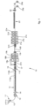
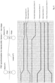
- Fig. 1 shows, as a whole, and schematically, an example of an apparatus 10 for the production of flat metal products in which the flying gauge change method described hereafter in detail can be applied. It is understood that the representation of fig. 1 is only an example to facilitate the understanding of the invention, which is completely non-binding for the application of the concepts presented below.
- the apparatus 10 comprises a control system suitable to receive the instructions relating to the cards relating to a determinate casting process, as well as relating to determinate flying gauge changes of the final product to be made, and to adjust the work parameters of all the rolling stands as a result of the flying gauge change as above.
- the apparatus 10 comprises, as constituent elements:
- the casting and rolling process carried out by the apparatus 10 can occur in endless, semi-endless and coil-to-coil modes.
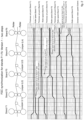
- Figs. 2-6 represent graphs which represent, by varying the specific parameters indicated, modes for the flying change of the final thickness of the strip of the type applicable in the apparatus 10 described above, in particular in the endless and/or semi-endless modes indicated above.
- a set-point of the new thickness is identified in the first finishing stand F1.
- the new thickness is smaller than the previous thickness (thickness reduction).
- the new gap between the rolling rollers, corresponding to the new thickness, of the first finishing stand F1 is set, and the speed of the rollers of the same stand F1 is increased simultaneously until it reaches the new set-point.
- the second step provides the application of the new set of inter-stand tension, in this case the tension of the strip is increased.
- the speed at which the material is fed in this case the casting speed, remains constant, as well as the speed of all the stands upstream of the stand F1, that is, of all the roughing stands.
- the speed at which the material is fed in this case the casting speed, remains constant, as well as the speed of all the stands upstream of the stand F1, that is, of all the roughing stands.
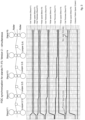
- the speed of the first stand H0 is not modified, as is the case for the other work parameters of the same stand H0.
- the first stand involved in the thickness change is the (second) stand H1 and the rotation speed of the rolling rollers is adjusted in two steps. The same applies to the (third) stand H2.
- the speed at which the material is fed in this case the casting speed, remains constant, as does the speed of the first roughing stand H0.
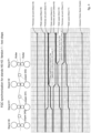
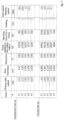
- Fig. 5 shows, in greater detail, the first embodiment of the two-step thickness change for the single stand (n th ); in particular, it is possible to observe when the new inter-stand tension set-ups and the new profile and flatness set-ups are actuated.
- Fig. 6 shows, in greater detail, the second embodiment of the simultaneous thickness change for the single stand (n th ); in particular, it is possible to observe how all the set-ups are actuated simultaneously: the application of the new force set-up (in this case an increase of the compression/reduction, the penultimate line of the graph) entails the simultaneous application of the new gap set-up (that is, of thickness reduction); simultaneously, the set-ups for the inter-stand tension and for the profile and flatness actuators are also modified.
- the new force set-up in this case an increase of the compression/reduction, the penultimate line of the graph
- the new speed set-up is calculated starting from the previous set-up with the aim of keeping the mass-flow unchanged.
- subsequent roller speed current roller speed * thickness in stand n th ⁇ subsequent / thickness in stand n th ⁇ current .
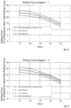
- Fig. 7 shows, by way of example only, an example of a variation of the set-up of parameters, from a current set-up to a subsequent set-up, in the event of a change from a final thickness of the strip of about 3 mm to a final thickness of the strip of about 2.3 mm.
- finishing stands F1-F5 are affected by the change of set-up of parameters.
- the reduction in the final thickness of the strip is accompanied by an increase in the speed of the rollers of the stands, as well as an increase in the compression force.
- the inter-stand tension also increases in relation to the thickness reduction to be obtained.
- Figs. 8 to 11 describe the modes in which another embodiment of the invention provides to calculate the number of stands involved in the flying gauge change (FGC).
- FGC flying gauge change
- the central continuous line represents the distribution of reference forces, while the two dashed lines above and below indicate the upper and lower tolerance range, within which the rolling force can vary without compromising the quality of the finished product.
- the overall rolling force (that is, the sum of the individual rolling forces on the 5 stands) will have to increase.
- the effective rolling force in the last two stands increases, but remains within the acceptable upper tolerance range. Consequently, the thickness change can be taken on by the last two stands of the finishing mill, without involving other stands upstream.
- Fig. 11 shows how the new distribution of forces on the finishing mill leads to a trend similar to the initial one of fig. 8 , but with a greater force value in all the stands, that is, the curve of the forces in all 5 finishing stands has the same trend but with an increased value compared to the beginning.
Landscapes
- Engineering & Computer Science (AREA)
- Mechanical Engineering (AREA)
- Metal Rolling (AREA)
- Control Of Metal Rolling (AREA)
Priority Applications (1)
| Application Number | Priority Date | Filing Date | Title |
|---|---|---|---|
| HRP20240382TT HRP20240382T1 (hr) | 2020-01-10 | 2020-12-04 | Postupak i uređaj za izradu plosnatih metalnih proizvoda |
Applications Claiming Priority (2)
| Application Number | Priority Date | Filing Date | Title |
|---|---|---|---|
| IT102020000000316A IT202000000316A1 (it) | 2020-01-10 | 2020-01-10 | Metodo ed apparato di produzione di prodotti metallici piani |
| PCT/IT2020/050302 WO2021140531A1 (en) | 2020-01-10 | 2020-12-04 | Method and apparatus for producing flat metal products |
Publications (3)
| Publication Number | Publication Date |
|---|---|
| EP4087692A1 EP4087692A1 (en) | 2022-11-16 |
| EP4087692B1 true EP4087692B1 (en) | 2024-01-31 |
| EP4087692C0 EP4087692C0 (en) | 2024-01-31 |
Family
ID=70009333
Family Applications (1)
| Application Number | Title | Priority Date | Filing Date |
|---|---|---|---|
| EP20829688.9A Active EP4087692B1 (en) | 2020-01-10 | 2020-12-04 | Method and apparatus for producing flat metal products |
Country Status (20)
| Country | Link |
|---|---|
| US (1) | US12064799B2 (pl) |
| EP (1) | EP4087692B1 (pl) |
| JP (1) | JP7404545B2 (pl) |
| KR (1) | KR102313670B1 (pl) |
| CN (1) | CN113102504B (pl) |
| AR (1) | AR119699A1 (pl) |
| CA (1) | CA3073246C (pl) |
| CL (1) | CL2020000622A1 (pl) |
| CO (1) | CO2020002991A1 (pl) |
| ES (1) | ES2975561T3 (pl) |
| HR (1) | HRP20240382T1 (pl) |
| HU (1) | HUE066489T2 (pl) |
| IT (1) | IT202000000316A1 (pl) |
| MY (1) | MY199281A (pl) |
| PE (1) | PE20211922A1 (pl) |
| PH (1) | PH12020050029A1 (pl) |
| PL (1) | PL4087692T3 (pl) |
| SA (1) | SA120410501B1 (pl) |
| UA (1) | UA128685C2 (pl) |
| WO (1) | WO2021140531A1 (pl) |
Families Citing this family (6)
| Publication number | Priority date | Publication date | Assignee | Title |
|---|---|---|---|---|
| IT202100031217A1 (it) * | 2021-12-13 | 2023-06-13 | Danieli Off Mecc | Procedimento ed impianto per la produzione di prodotti laminati piani |
| DE102022208499A1 (de) | 2022-08-16 | 2024-02-22 | Sms Group Gmbh | Verfahren und Computerprogrammprodukt zum Betreiben einer Gieß-Walzanlage |
| CN117046895B (zh) * | 2023-07-07 | 2025-12-30 | 山东钢铁集团日照有限公司 | 一种改善1500MPa级别冷轧热成型钢扁卷的方法及其应用 |
| IT202300018720A1 (it) * | 2023-09-12 | 2025-03-12 | Danieli Off Mecc | Impianto di colata e laminazione in continuo per la produzione di nastri metallici e relativa procedura in caso di fermata del laminatoio |
| CN117086642A (zh) * | 2023-09-14 | 2023-11-21 | 中冶赛迪工程技术股份有限公司 | 热轧板带纵横剪压设备及热轧板带剪切生产线 |
| DE102024122428B3 (de) * | 2024-08-06 | 2025-12-04 | Sms Group Gmbh | Betriebsverfahren, Steuervorrichtung und Walzanlage |
Citations (18)
| Publication number | Priority date | Publication date | Assignee | Title |
|---|---|---|---|---|
| US4335435A (en) * | 1978-11-01 | 1982-06-15 | Mitsubishi Denki Kabushiki Kaisha | Method of changing rolling schedule during rolling in tandem rolling mill |
| JPS57168719A (en) | 1981-04-10 | 1982-10-18 | Nippon Kokan Kk <Nkk> | Changing method of plate thickness in plate rolling |
| JPS5982102A (ja) | 1982-10-30 | 1984-05-12 | Toshiba Corp | 圧延方法 |
| JPH06339715A (ja) | 1993-05-31 | 1994-12-13 | Nkk Corp | 熱延ストリップの走間板厚変更圧延方法 |
| JPH0773734B2 (ja) | 1988-02-19 | 1995-08-09 | 株式会社日立製作所 | タンデムミルの速度制御装置 |
| EP0730916A1 (en) | 1995-03-03 | 1996-09-11 | Kabushiki Kaisha Toshiba | Hot rolling method and apparatus |
| WO1999004915A1 (en) | 1997-07-21 | 1999-02-04 | Kvaerner Metals Continuous Casting Limited | Continuous metal manufacturing method and apparatus therefor |
| WO1999024183A1 (de) | 1997-11-07 | 1999-05-20 | Siemens Aktiengesellschaft | Verfahren und einrichtung zum walzen eines walzbandes mit variierender dicke |
| US20040232605A1 (en) | 2001-08-07 | 2004-11-25 | Dieter Rosenthal | Hot rolling installation |
| WO2006106376A1 (en) | 2005-04-07 | 2006-10-12 | Giovanni Arvedi | Process and system for manufacturing metal strips and sheets without solution of continuity between continuous casting and rolling |
| JP2011189368A (ja) | 2010-03-15 | 2011-09-29 | Sumitomo Metal Ind Ltd | タンデム仕上圧延機及びその動作制御方法、並びに、熱延鋼板の製造装置及び熱延鋼板の製造方法 |
| EP2346625B1 (de) | 2008-10-30 | 2013-05-29 | Siemens Aktiengesellschaft | Verfahren zur einstellung einer auslaufdicke eines eine mehrgerüstige walzstrasse durchlaufenden walzguts, steuer- und/oder regeleinrichtung und walzanlage |
| KR101442891B1 (ko) | 2011-12-22 | 2014-09-22 | 주식회사 포스코 | 조압연 장치 및 방법 |
| JP5733230B2 (ja) | 2012-02-09 | 2015-06-10 | 東芝三菱電機産業システム株式会社 | 熱間圧延ラインの制御装置 |
| EP3000539A1 (de) | 2014-09-24 | 2016-03-30 | SMS group GmbH | Verfahren und Gieß-Walz-Anlage zum Gießen und Walzen eines endlosen Stranggutes |
| WO2017036769A1 (de) * | 2015-08-28 | 2017-03-09 | Sms Group Gmbh | Anlage nach dem csp-konzept sowie verfahren zum betreiben einer solchen anlage |
| CN106583453A (zh) | 2016-12-27 | 2017-04-26 | 中冶南方工程技术有限公司 | 一种应用薄板坯连铸连轧工艺生产超薄低碳钢的方法 |
| WO2019026292A1 (ja) | 2017-08-04 | 2019-02-07 | 東芝三菱電機産業システム株式会社 | エンドレス圧延ラインの温度制御装置 |
Family Cites Families (21)
| Publication number | Priority date | Publication date | Assignee | Title |
|---|---|---|---|---|
| US3852983A (en) * | 1973-04-25 | 1974-12-10 | Westinghouse Electric Corp | Work strip gauge change during rolling in a tandem rolling mill |
| JPS61273210A (ja) * | 1985-05-27 | 1986-12-03 | Nippon Steel Corp | タンデム圧延機の走間スケジユ−ル変更方法 |
| JPH01202305A (ja) * | 1988-02-05 | 1989-08-15 | Sumitomo Metal Ind Ltd | 走間板厚変更制御装置 |
| JPH0615317A (ja) * | 1992-07-01 | 1994-01-25 | Toshiba Corp | 熱間仕上圧延機の制御方法 |
| JP3273594B2 (ja) | 1997-09-05 | 2002-04-08 | 川崎製鉄株式会社 | 冷間タンデム圧延機における走間板厚変更方法 |
| KR100448620B1 (ko) * | 1999-12-24 | 2004-09-13 | 주식회사 포스코 | 냉간압연 주행간 판두께 변경구간에서의 두께제어방법 |
| JP4696348B2 (ja) * | 2000-10-04 | 2011-06-08 | Jfeスチール株式会社 | エンドレス熱間圧延方法 |
| KR20020048485A (ko) * | 2000-12-18 | 2002-06-24 | 이구택 | 연속 냉간압연 공정의 주행간 두께변경구간에서두께제어방법 |
| KR100513775B1 (ko) * | 2000-12-23 | 2005-09-09 | 주식회사 포스코 | 두께변경 구간에서의 판두께 제어방법 |
| JP3947116B2 (ja) * | 2003-02-26 | 2007-07-18 | 東芝三菱電機産業システム株式会社 | 連続圧延機の走間板厚変更装置 |
| FR2853570B1 (fr) * | 2003-04-11 | 2005-07-01 | Vai Clecim | Procede et dispositif de regulation de l'epaisseur d'un produit lamine |
| US20080223100A1 (en) * | 2005-05-11 | 2008-09-18 | Corus Staal Bv | Method and Apparatus for Producing Strip Having a Variable Thickness |
| DE102007058709A1 (de) * | 2007-08-04 | 2009-02-05 | Sms Demag Ag | Verfahren zum Herstellen eines Bandes aus Stahl |
| CN101733289B (zh) * | 2009-12-23 | 2012-07-04 | 北京理工大学 | 一种热轧板带连轧轧制规程动态设定的方法 |
| JP4801782B1 (ja) * | 2010-04-06 | 2011-10-26 | 住友金属工業株式会社 | タンデム圧延機の動作制御方法及びこれを用いた熱延鋼板の製造方法 |
| IT1400002B1 (it) * | 2010-05-10 | 2013-05-09 | Danieli Off Mecc | Procedimento ed impianto per la produzione di prodotti laminati piani |
| JP5807499B2 (ja) * | 2011-10-06 | 2015-11-10 | Jfeスチール株式会社 | 鋼帯の連続冷間圧延方法 |
| JP5820346B2 (ja) * | 2012-07-31 | 2015-11-24 | 株式会社日立製作所 | 圧延制御装置及び圧延制御方法 |
| KR101510568B1 (ko) * | 2013-12-23 | 2015-04-08 | 주식회사 포스코 | 연연속 압연장치 및 연연속 압연방법 |
| KR101674773B1 (ko) * | 2014-12-26 | 2016-11-10 | 주식회사 포스코 | 마무리압연기에서의 스트립 메탈 아웃 방법 |
| SI3097992T1 (sl) * | 2015-05-29 | 2017-10-30 | Giebel Kaltwalzwerk Gmbh | Postopek za stopenjsko valjanje kovinskega traku |
-
2020
- 2020-01-10 IT IT102020000000316A patent/IT202000000316A1/it unknown
- 2020-02-06 CN CN202010081753.5A patent/CN113102504B/zh active Active
- 2020-02-21 KR KR1020200021727A patent/KR102313670B1/ko active Active
- 2020-02-21 CA CA3073246A patent/CA3073246C/en active Active
- 2020-02-28 AR ARP200100557A patent/AR119699A1/es active IP Right Grant
- 2020-02-28 PH PH12020050029A patent/PH12020050029A1/en unknown
- 2020-03-03 MY MYPI2020001105A patent/MY199281A/en unknown
- 2020-03-09 SA SA120410501A patent/SA120410501B1/ar unknown
- 2020-03-10 CL CL2020000622A patent/CL2020000622A1/es unknown
- 2020-03-12 PE PE2020000356A patent/PE20211922A1/es unknown
- 2020-03-13 CO CONC2020/0002991A patent/CO2020002991A1/es unknown
- 2020-12-04 EP EP20829688.9A patent/EP4087692B1/en active Active
- 2020-12-04 ES ES20829688T patent/ES2975561T3/es active Active
- 2020-12-04 HU HUE20829688A patent/HUE066489T2/hu unknown
- 2020-12-04 UA UAA202202904A patent/UA128685C2/uk unknown
- 2020-12-04 JP JP2022542274A patent/JP7404545B2/ja active Active
- 2020-12-04 PL PL20829688.9T patent/PL4087692T3/pl unknown
- 2020-12-04 WO PCT/IT2020/050302 patent/WO2021140531A1/en not_active Ceased
- 2020-12-04 HR HRP20240382TT patent/HRP20240382T1/hr unknown
- 2020-12-04 US US17/791,761 patent/US12064799B2/en active Active
Patent Citations (18)
| Publication number | Priority date | Publication date | Assignee | Title |
|---|---|---|---|---|
| US4335435A (en) * | 1978-11-01 | 1982-06-15 | Mitsubishi Denki Kabushiki Kaisha | Method of changing rolling schedule during rolling in tandem rolling mill |
| JPS57168719A (en) | 1981-04-10 | 1982-10-18 | Nippon Kokan Kk <Nkk> | Changing method of plate thickness in plate rolling |
| JPS5982102A (ja) | 1982-10-30 | 1984-05-12 | Toshiba Corp | 圧延方法 |
| JPH0773734B2 (ja) | 1988-02-19 | 1995-08-09 | 株式会社日立製作所 | タンデムミルの速度制御装置 |
| JPH06339715A (ja) | 1993-05-31 | 1994-12-13 | Nkk Corp | 熱延ストリップの走間板厚変更圧延方法 |
| EP0730916A1 (en) | 1995-03-03 | 1996-09-11 | Kabushiki Kaisha Toshiba | Hot rolling method and apparatus |
| WO1999004915A1 (en) | 1997-07-21 | 1999-02-04 | Kvaerner Metals Continuous Casting Limited | Continuous metal manufacturing method and apparatus therefor |
| WO1999024183A1 (de) | 1997-11-07 | 1999-05-20 | Siemens Aktiengesellschaft | Verfahren und einrichtung zum walzen eines walzbandes mit variierender dicke |
| US20040232605A1 (en) | 2001-08-07 | 2004-11-25 | Dieter Rosenthal | Hot rolling installation |
| WO2006106376A1 (en) | 2005-04-07 | 2006-10-12 | Giovanni Arvedi | Process and system for manufacturing metal strips and sheets without solution of continuity between continuous casting and rolling |
| EP2346625B1 (de) | 2008-10-30 | 2013-05-29 | Siemens Aktiengesellschaft | Verfahren zur einstellung einer auslaufdicke eines eine mehrgerüstige walzstrasse durchlaufenden walzguts, steuer- und/oder regeleinrichtung und walzanlage |
| JP2011189368A (ja) | 2010-03-15 | 2011-09-29 | Sumitomo Metal Ind Ltd | タンデム仕上圧延機及びその動作制御方法、並びに、熱延鋼板の製造装置及び熱延鋼板の製造方法 |
| KR101442891B1 (ko) | 2011-12-22 | 2014-09-22 | 주식회사 포스코 | 조압연 장치 및 방법 |
| JP5733230B2 (ja) | 2012-02-09 | 2015-06-10 | 東芝三菱電機産業システム株式会社 | 熱間圧延ラインの制御装置 |
| EP3000539A1 (de) | 2014-09-24 | 2016-03-30 | SMS group GmbH | Verfahren und Gieß-Walz-Anlage zum Gießen und Walzen eines endlosen Stranggutes |
| WO2017036769A1 (de) * | 2015-08-28 | 2017-03-09 | Sms Group Gmbh | Anlage nach dem csp-konzept sowie verfahren zum betreiben einer solchen anlage |
| CN106583453A (zh) | 2016-12-27 | 2017-04-26 | 中冶南方工程技术有限公司 | 一种应用薄板坯连铸连轧工艺生产超薄低碳钢的方法 |
| WO2019026292A1 (ja) | 2017-08-04 | 2019-02-07 | 東芝三菱電機産業システム株式会社 | エンドレス圧延ラインの温度制御装置 |
Non-Patent Citations (3)
| Title |
|---|
| ANBE K.Y., SEKIGUCHI K., TSUJI T., UENO S.: "Flying Gauge Change Control for Hot Strip Finishing Mill", 5TH IFAC SYMPOSIUM ON MODELLING AND CONTROL IN BIOMEDICAL SYSTEMS 2003, MELBOURNE, AUSTRALIA, 21-23 AUGUST 2003, vol. 26, no. 2, 1 July 1993 (1993-07-01), pages 585 - 588, XP093231008, ISSN: 1474-6670, DOI: 10.1016/S1474-6670(17)48536-3 |
| ANONYMOUS: "Solutions for the Global Metals Industry", TMEIC CORPORATION. WE DRIVE INDUSTRY, 1 January 2011 (2011-01-01), pages 1 - 40, XP093230981 |
| TUROWSKI BILL, BLAIKLOCK PAUL: "Flying Gage Change Technology for Hot Strip Mills", TMEIC, ENERGY SAVINGS FOR THE METALS INDUSTRY, 1 January 2000 (2000-01-01), pages 1 - 3, XP093230963 |
Also Published As
| Publication number | Publication date |
|---|---|
| MY199281A (en) | 2023-10-24 |
| PL4087692T3 (pl) | 2024-05-06 |
| CA3073246A1 (en) | 2021-07-10 |
| PE20211922A1 (es) | 2021-09-28 |
| CN113102504A (zh) | 2021-07-13 |
| EP4087692C0 (en) | 2024-01-31 |
| KR102313670B1 (ko) | 2021-10-19 |
| IT202000000316A1 (it) | 2021-07-10 |
| HUE066489T2 (hu) | 2024-08-28 |
| CA3073246C (en) | 2022-06-07 |
| SA120410501B1 (ar) | 2022-09-25 |
| CL2020000622A1 (es) | 2021-01-15 |
| AR119699A1 (es) | 2022-01-05 |
| EP4087692A1 (en) | 2022-11-16 |
| HRP20240382T1 (hr) | 2024-06-07 |
| JP2023509217A (ja) | 2023-03-07 |
| KR20210091020A (ko) | 2021-07-21 |
| CN113102504B (zh) | 2024-01-02 |
| JP7404545B2 (ja) | 2023-12-25 |
| CO2020002991A1 (es) | 2021-09-20 |
| WO2021140531A1 (en) | 2021-07-15 |
| US12064799B2 (en) | 2024-08-20 |
| PH12020050029A1 (en) | 2021-07-26 |
| BR102020003540A2 (pt) | 2021-07-27 |
| ES2975561T3 (es) | 2024-07-09 |
| UA128685C2 (uk) | 2024-09-25 |
| US20230042075A1 (en) | 2023-02-09 |
Similar Documents
| Publication | Publication Date | Title |
|---|---|---|
| EP4087692B1 (en) | Method and apparatus for producing flat metal products | |
| CN1103647C (zh) | 制造热轧钢带的方法和设备 | |
| EP2569104B1 (en) | Method for the production of flat rolled products | |
| JP4677097B2 (ja) | 熱間圧延薄板製品をエンドレス製造するための生産方法及び生産設備 | |
| US9186711B2 (en) | Rolling line and relative method | |
| US9126246B2 (en) | Rolling method for flat products and relative rolling line | |
| CN107073534A (zh) | 用于铸造和轧制无头连铸坯材的方法和铸造轧制设备 | |
| GB2322320A (en) | Continuous casting with rolling stages separated by a temperature controlling stage | |
| EP4122612A1 (en) | Six-high rolling mill stand and finishing mill train for hot rolling an intermediate strip into a thin strip | |
| RU2735643C1 (ru) | Способ и устройство для изготовления продуктов плоского металлопроката | |
| OA19989A (en) | Method and apparatus for producing flat metal products. | |
| US20230330740A1 (en) | Method to produce a metal strip, and production plant implementing said method | |
| WO1999004915A1 (en) | Continuous metal manufacturing method and apparatus therefor | |
| JP2024545647A (ja) | 圧延製品を製造するためのプラントおよび方法 | |
| JP3495178B2 (ja) | 鋼片の連続熱間圧延方法 | |
| BR102020003540B1 (pt) | Método e aparelho de produção de produtos planos de metal | |
| GB1603161A (en) | Rolling of slabs into hot strip |
Legal Events
| Date | Code | Title | Description |
|---|---|---|---|
| REG | Reference to a national code |
Ref country code: HR Ref legal event code: TUEP Ref document number: P20240382T Country of ref document: HR |
|
| STAA | Information on the status of an ep patent application or granted ep patent |
Free format text: STATUS: UNKNOWN |
|
| STAA | Information on the status of an ep patent application or granted ep patent |
Free format text: STATUS: THE INTERNATIONAL PUBLICATION HAS BEEN MADE |
|
| PUAI | Public reference made under article 153(3) epc to a published international application that has entered the european phase |
Free format text: ORIGINAL CODE: 0009012 |
|
| STAA | Information on the status of an ep patent application or granted ep patent |
Free format text: STATUS: REQUEST FOR EXAMINATION WAS MADE |
|
| 17P | Request for examination filed |
Effective date: 20220719 |
|
| AK | Designated contracting states |
Kind code of ref document: A1 Designated state(s): AL AT BE BG CH CY CZ DE DK EE ES FI FR GB GR HR HU IE IS IT LI LT LU LV MC MK MT NL NO PL PT RO RS SE SI SK SM TR |
|
| TPAC | Observations filed by third parties |
Free format text: ORIGINAL CODE: EPIDOSNTIPA |
|
| DAV | Request for validation of the european patent (deleted) | ||
| DAX | Request for extension of the european patent (deleted) | ||
| P01 | Opt-out of the competence of the unified patent court (upc) registered |
Effective date: 20230517 |
|
| GRAP | Despatch of communication of intention to grant a patent |
Free format text: ORIGINAL CODE: EPIDOSNIGR1 |
|
| STAA | Information on the status of an ep patent application or granted ep patent |
Free format text: STATUS: GRANT OF PATENT IS INTENDED |
|
| INTG | Intention to grant announced |
Effective date: 20230817 |
|
| GRAS | Grant fee paid |
Free format text: ORIGINAL CODE: EPIDOSNIGR3 |
|
| GRAA | (expected) grant |
Free format text: ORIGINAL CODE: 0009210 |
|
| STAA | Information on the status of an ep patent application or granted ep patent |
Free format text: STATUS: THE PATENT HAS BEEN GRANTED |
|
| AK | Designated contracting states |
Kind code of ref document: B1 Designated state(s): AL AT BE BG CH CY CZ DE DK EE ES FI FR GB GR HR HU IE IS IT LI LT LU LV MC MK MT NL NO PL PT RO RS SE SI SK SM TR |
|
| REG | Reference to a national code |
Ref country code: GB Ref legal event code: FG4D Ref country code: CH Ref legal event code: EP |
|
| REG | Reference to a national code |
Ref country code: DE Ref legal event code: R096 Ref document number: 602020025111 Country of ref document: DE |
|
| REG | Reference to a national code |
Ref country code: IE Ref legal event code: FG4D |
|
| U01 | Request for unitary effect filed |
Effective date: 20240228 |
|
| U07 | Unitary effect registered |
Designated state(s): AT BE BG DE DK EE FI FR IT LT LU LV MT NL PT SE SI Effective date: 20240306 |
|
| P04 | Withdrawal of opt-out of the competence of the unified patent court (upc) registered |
Effective date: 20240412 |
|
| REG | Reference to a national code |
Ref country code: SK Ref legal event code: T3 Ref document number: E 43935 Country of ref document: SK |
|
| REG | Reference to a national code |
Ref country code: HR Ref legal event code: T1PR Ref document number: P20240382 Country of ref document: HR |
|
| PG25 | Lapsed in a contracting state [announced via postgrant information from national office to epo] |
Ref country code: IS Free format text: LAPSE BECAUSE OF FAILURE TO SUBMIT A TRANSLATION OF THE DESCRIPTION OR TO PAY THE FEE WITHIN THE PRESCRIBED TIME-LIMIT Effective date: 20240531 |
|
| REG | Reference to a national code |
Ref country code: ES Ref legal event code: FG2A Ref document number: 2975561 Country of ref document: ES Kind code of ref document: T3 Effective date: 20240709 |
|
| PG25 | Lapsed in a contracting state [announced via postgrant information from national office to epo] |
Ref country code: GR Free format text: LAPSE BECAUSE OF FAILURE TO SUBMIT A TRANSLATION OF THE DESCRIPTION OR TO PAY THE FEE WITHIN THE PRESCRIBED TIME-LIMIT Effective date: 20240501 |
|
| PG25 | Lapsed in a contracting state [announced via postgrant information from national office to epo] |
Ref country code: RS Free format text: LAPSE BECAUSE OF FAILURE TO SUBMIT A TRANSLATION OF THE DESCRIPTION OR TO PAY THE FEE WITHIN THE PRESCRIBED TIME-LIMIT Effective date: 20240430 |
|
| PG25 | Lapsed in a contracting state [announced via postgrant information from national office to epo] |
Ref country code: RS Free format text: LAPSE BECAUSE OF FAILURE TO SUBMIT A TRANSLATION OF THE DESCRIPTION OR TO PAY THE FEE WITHIN THE PRESCRIBED TIME-LIMIT Effective date: 20240430 Ref country code: NO Free format text: LAPSE BECAUSE OF FAILURE TO SUBMIT A TRANSLATION OF THE DESCRIPTION OR TO PAY THE FEE WITHIN THE PRESCRIBED TIME-LIMIT Effective date: 20240430 Ref country code: IS Free format text: LAPSE BECAUSE OF FAILURE TO SUBMIT A TRANSLATION OF THE DESCRIPTION OR TO PAY THE FEE WITHIN THE PRESCRIBED TIME-LIMIT Effective date: 20240531 Ref country code: GR Free format text: LAPSE BECAUSE OF FAILURE TO SUBMIT A TRANSLATION OF THE DESCRIPTION OR TO PAY THE FEE WITHIN THE PRESCRIBED TIME-LIMIT Effective date: 20240501 |
|
| REG | Reference to a national code |
Ref country code: HU Ref legal event code: AG4A Ref document number: E066489 Country of ref document: HU |
|
| REG | Reference to a national code |
Ref country code: DE Ref legal event code: R026 Ref document number: 602020025111 Country of ref document: DE |
|
| PLBI | Opposition filed |
Free format text: ORIGINAL CODE: 0009260 |
|
| PG25 | Lapsed in a contracting state [announced via postgrant information from national office to epo] |
Ref country code: SM Free format text: LAPSE BECAUSE OF FAILURE TO SUBMIT A TRANSLATION OF THE DESCRIPTION OR TO PAY THE FEE WITHIN THE PRESCRIBED TIME-LIMIT Effective date: 20240131 |
|
| PG25 | Lapsed in a contracting state [announced via postgrant information from national office to epo] |
Ref country code: CZ Free format text: LAPSE BECAUSE OF FAILURE TO SUBMIT A TRANSLATION OF THE DESCRIPTION OR TO PAY THE FEE WITHIN THE PRESCRIBED TIME-LIMIT Effective date: 20240131 |
|
| PG25 | Lapsed in a contracting state [announced via postgrant information from national office to epo] |
Ref country code: SM Free format text: LAPSE BECAUSE OF FAILURE TO SUBMIT A TRANSLATION OF THE DESCRIPTION OR TO PAY THE FEE WITHIN THE PRESCRIBED TIME-LIMIT Effective date: 20240131 Ref country code: RO Free format text: LAPSE BECAUSE OF FAILURE TO SUBMIT A TRANSLATION OF THE DESCRIPTION OR TO PAY THE FEE WITHIN THE PRESCRIBED TIME-LIMIT Effective date: 20240131 Ref country code: CZ Free format text: LAPSE BECAUSE OF FAILURE TO SUBMIT A TRANSLATION OF THE DESCRIPTION OR TO PAY THE FEE WITHIN THE PRESCRIBED TIME-LIMIT Effective date: 20240131 |
|
| 26 | Opposition filed |
Opponent name: PRIMETALS TECHNOLOGIES AUSTRIA GMBH Effective date: 20241002 |
|
| PLAX | Notice of opposition and request to file observation + time limit sent |
Free format text: ORIGINAL CODE: EPIDOSNOBS2 |
|
| REG | Reference to a national code |
Ref country code: HR Ref legal event code: ODRP Ref document number: P20240382 Country of ref document: HR Payment date: 20241120 Year of fee payment: 5 |
|
| U20 | Renewal fee for the european patent with unitary effect paid |
Year of fee payment: 5 Effective date: 20241227 |
|
| PLBB | Reply of patent proprietor to notice(s) of opposition received |
Free format text: ORIGINAL CODE: EPIDOSNOBS3 |
|
| PGFP | Annual fee paid to national office [announced via postgrant information from national office to epo] |
Ref country code: ES Payment date: 20250102 Year of fee payment: 5 |
|
| PGFP | Annual fee paid to national office [announced via postgrant information from national office to epo] |
Ref country code: CH Payment date: 20250108 Year of fee payment: 5 |
|
| PG25 | Lapsed in a contracting state [announced via postgrant information from national office to epo] |
Ref country code: MC Free format text: LAPSE BECAUSE OF FAILURE TO SUBMIT A TRANSLATION OF THE DESCRIPTION OR TO PAY THE FEE WITHIN THE PRESCRIBED TIME-LIMIT Effective date: 20240131 |
|
| GBPC | Gb: european patent ceased through non-payment of renewal fee |
Effective date: 20241204 |
|
| PG25 | Lapsed in a contracting state [announced via postgrant information from national office to epo] |
Ref country code: GB Free format text: LAPSE BECAUSE OF NON-PAYMENT OF DUE FEES Effective date: 20241204 |
|
| PG25 | Lapsed in a contracting state [announced via postgrant information from national office to epo] |
Ref country code: IE Free format text: LAPSE BECAUSE OF NON-PAYMENT OF DUE FEES Effective date: 20241204 |
|
| REG | Reference to a national code |
Ref country code: HR Ref legal event code: ODRP Ref document number: P20240382 Country of ref document: HR Payment date: 20251120 Year of fee payment: 6 |
|
| REG | Reference to a national code |
Ref country code: CH Ref legal event code: U11 Free format text: ST27 STATUS EVENT CODE: U-0-0-U10-U11 (AS PROVIDED BY THE NATIONAL OFFICE) Effective date: 20260101 |
|
| PGFP | Annual fee paid to national office [announced via postgrant information from national office to epo] |
Ref country code: HR Payment date: 20251120 Year of fee payment: 6 Ref country code: HU Payment date: 20251124 Year of fee payment: 6 |
|
| PGFP | Annual fee paid to national office [announced via postgrant information from national office to epo] |
Ref country code: TR Payment date: 20251121 Year of fee payment: 6 |
|
| PGFP | Annual fee paid to national office [announced via postgrant information from national office to epo] |
Ref country code: PL Payment date: 20251118 Year of fee payment: 6 |
|
| PGFP | Annual fee paid to national office [announced via postgrant information from national office to epo] |
Ref country code: SK Payment date: 20251119 Year of fee payment: 6 |
|
| U20 | Renewal fee for the european patent with unitary effect paid |
Year of fee payment: 6 Effective date: 20251229 |