EP4086019B1 - Vorrichtung zum schneiden von gitterfüssen - Google Patents
Vorrichtung zum schneiden von gitterfüssen Download PDFInfo
- Publication number
- EP4086019B1 EP4086019B1 EP21904991.3A EP21904991A EP4086019B1 EP 4086019 B1 EP4086019 B1 EP 4086019B1 EP 21904991 A EP21904991 A EP 21904991A EP 4086019 B1 EP4086019 B1 EP 4086019B1
- Authority
- EP
- European Patent Office
- Prior art keywords
- cutoff
- arms
- truss
- footing
- crankshaft
- Prior art date
- Legal status (The legal status is an assumption and is not a legal conclusion. Google has not performed a legal analysis and makes no representation as to the accuracy of the status listed.)
- Active
Links
Images


Classifications
-
- B—PERFORMING OPERATIONS; TRANSPORTING
- B21—MECHANICAL METAL-WORKING WITHOUT ESSENTIALLY REMOVING MATERIAL; PUNCHING METAL
- B21F—WORKING OR PROCESSING OF METAL WIRE
- B21F27/00—Making wire network, i.e. wire nets
- B21F27/12—Making special types or portions of network by methods or means specially adapted therefor
-
- B—PERFORMING OPERATIONS; TRANSPORTING
- B21—MECHANICAL METAL-WORKING WITHOUT ESSENTIALLY REMOVING MATERIAL; PUNCHING METAL
- B21F—WORKING OR PROCESSING OF METAL WIRE
- B21F11/00—Cutting wire
-
- B—PERFORMING OPERATIONS; TRANSPORTING
- B21—MECHANICAL METAL-WORKING WITHOUT ESSENTIALLY REMOVING MATERIAL; PUNCHING METAL
- B21F—WORKING OR PROCESSING OF METAL WIRE
- B21F15/00—Connecting wire to wire or other metallic material or objects; Connecting parts by means of wire
- B21F15/02—Connecting wire to wire or other metallic material or objects; Connecting parts by means of wire wire with wire
- B21F15/06—Connecting wire to wire or other metallic material or objects; Connecting parts by means of wire wire with wire with additional connecting elements or material
- B21F15/08—Connecting wire to wire or other metallic material or objects; Connecting parts by means of wire wire with wire with additional connecting elements or material making use of soldering or welding
-
- B—PERFORMING OPERATIONS; TRANSPORTING
- B21—MECHANICAL METAL-WORKING WITHOUT ESSENTIALLY REMOVING MATERIAL; PUNCHING METAL
- B21F—WORKING OR PROCESSING OF METAL WIRE
- B21F9/00—Straining wire
- B21F9/02—Straining wire by tools adapted also for making connections
Definitions
- the present application relates to the field of truss processing techniques and, in particular, to a truss footing cutoff device.
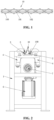
- the steel bar truss deck is formed by welding a bottom plate to a steel bar truss, and the steel bar truss is formed by welding an upper chord rib 101, a lower chord rib 102 and a truss footing 100 connecting the upper and lower chord ribs (shown in FIG. 1 ).
- the truss footing 100 is made of wave-shaped rebars. At present, the truss cutoff operation is involved in the truss production line, and typically, avoids the position of the truss footing.
- the truss footing is usually cut off by manually using a toothless saw or the like.
- Such cutoff manner has some problems, for example, the length precision of the steel bar truss is difficult to control, and the production efficiency is low. Moreover, the labor intensity of the operator is too high, and there is a potential safety hazard.
- the present application provides a truss footing cutoff device to solve problems of low production efficiency and high labor intensity existing in the existing truss footing cutoff manner.
- the truss footing cutoff device includes a rack; a fixed blade holder; two cutoff arms and a driving member.
- the fixed blade holder is fixed on the rack.
- Two fixed blades are symmetrically arranged on the fixed blade holder, the fixed blade holder is configured to support a truss, and each of the two fixed blades is configured to support a truss footing of the truss.
- the two cutoff arms are symmetrically arranged on the rack. Each of the two cutoff arms is provided with a movable blade.
- the driving member is mounted on the rack and is configured to drive the two cutoff arms to move, so that the each of the two cutoff arms drives the movable blade to get close to a respective one of the two fixed blades, and the movable blade cooperates with the respective one of the two fixed blades to cut off the truss footing.
- the two cutoff arms are rotatably mounted on the rack, the driving member is capable of driving the two cutoff arms to rotate, and the movable blade is mounted at one end of the each of the two cutoff arms and is capable of being driven by the each of the two cutoff arms to rotate.
- the truss footing cutoff device further includes a transmission assembly.
- the transmission assembly includes a crankshaft rotatably mounted on the rack and two connecting arms mounted on the crankshaft and capable of only rotating relative to the crankshaft, each of the two connecting arms is rotatably connected to a respective one of the two cutoff arms, the driving member is drivingly connected to the crankshaft and is capable of driving the crankshaft to rotate, and the crankshaft is capable of driving the two connecting arms to stretch out and draw back synchronously when the crankshaft rotates.
- the crankshaft includes a first connecting part and a second connecting part, a central axis of the first connecting part and a central axis of the second connecting part are symmetrically arranged with respect to a centerline of the crankshaft, one of the two connecting arms is rotatably connected to the first connecting part and the other one of the two connecting arms is rotatably connected to the second connecting part.
- the two cutoff arms are slidably mounted on the rack, the driving member is capable of driving the two cutoff arms to slide, and the movable blade is mounted at one end of the each of the two cutoff arms and is capable of being driven by the each of the two cutoff arms to move towards the fixed blade.
- the driving member is an air cylinder or an oil cylinder, and an output end of the air cylinder or the oil cylinder is connected to the two cutoff arms.
- the fixed blade holder includes a supporting part and two mounting parts located at two sides of the supporting part, the supporting part is configured to support the truss, and the two fixed blades are fixedly mounted on the two mounting parts respectively.
- connection to each other is to be construed in a broad sense, for example, as securely connected, detachably connected or integrated; mechanically connected or electrically connected; directly connected to each other or indirectly connected to each other via an intermediary; or internally connected between two components or interaction relations between two components.
- connection detachably connected or integrated; mechanically connected or electrically connected; directly connected to each other or indirectly connected to each other via an intermediary; or internally connected between two components or interaction relations between two components.
- first feature and the second feature may be in direct contact or be in contact via another feature between the two features.
- first feature is described as “on”, “above”, or “over” the second feature, the first feature is right on, above, or over the second feature or the first feature is obliquely on, above, or over the second feature, or the first feature is simply at a higher level than the second feature.
- the first feature When the first feature is described as “under”, “below”, or “underneath” the second feature, the first feature is right under, below, or underneath the second feature or the first feature is obliquely under, below, or underneath the second feature, or the first feature is simply at a lower level than the second feature.
- orientation or position relationships indicated by terms “above”, “below”, “right” and the like are based on the orientation or position relationships shown in the drawings, merely for ease of description and simplifying an operation, and these relationships do not indicate or imply that the referred device or element has a specific orientation and is constructed and operated in a specific orientation, and thus it is not to be construed as limiting the present application.
- the terms “first” and “second” are used only to distinguish between descriptions and have no special meaning.
- the present application provides a truss footing cutoff device, which can achieve the automatic cutoff of a truss footing 100 of a truss 10 without the manual cutoff, and thus has a higher automation degree, improves the production efficiency, and reduces the labor intensity of the operator and the potential safety hazard.
- the truss footing cutoff device includes a rack 1, a fixed blade holder 2, a fixed blade 3, a cutoff arm 4, a movable blade 5, a driving member 6 and a transmission assembly 7.
- the rack 1 is configured to carry the fixed blade holder 2, the fixed blade 3, the cutoff arm 4, the movable blade 5, the driving member 6 and the transmission assembly 7 to achieve the cutoff operation of the truss footing 100.
- the fixed blade holder 2 is fixed to the rack 1 and is optionally placed at a top position of the rack 1.
- a shape of the fixed blade holder 2 is adapted to a shape of the truss 10.
- the fixed blade holder 2 includes a supporting part 21 and mounting parts 22 located at two sides of the supporting part 21.
- the supporting part 21 is substantially in an inverted trapezoidal structure, and the truss 10 can be placed on and supported by the support part 21.
- the mounting part 22 is configured to fix and mount the fixed blade 3, and when the truss 10 is placed on the support part 21, the truss footing 100 can be placed on the fixed blade 3.
- the cutoff arm 4 is mounted on the rack 1 and is rotatable relative to the rack 1.As shown in FIG. 4 , an upper-middle position of the cutoff arm 4 is rotatably connected to the rack 1 through a rotary shaft.
- the movable blade 5 is mounted at one end of the cutoff arm 4 close to the rotary shaft, and the movable blade 5 can get close to or move away from the fixed blade 3 with the rotation of the cutoff arm 4.
- the cutoff arm 4 drives the movable blade 5 to get close to the fixed blade 3, the movable blade 5 and the fixed blade 3 cooperate to cut the truss footing 100.
- two cutoff arms 4 are symmetrically arranged on the rack 1, and correspondingly, two movable blades 5 and two fixed blades 3 are also symmetrically arranged, thereby achieving the cutoff of truss footings 100 on two sides of the truss 10.
- the driving member 6 is configured to drive the cutoff arm 4 to rotate relative to the rack 1.
- the driving member 6 may be a motor or a deceleration motor.
- Two driving members 6 may be provided, where each driving member 6 drives one cutoff arm 4 to rotate so as to cut off the truss footing 100.
- the two driving members 6 synchronously operate to synchronously cut off the truss footings 100 on two sides of the truss 10 at a same position, thereby improving the cutoff efficiency.
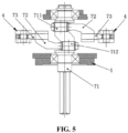
- the above transmission assembly 7 includes a crankshaft 71, connecting arms 72 and connecting rods 73.
- the crankshaft 71 is rotatably mounted on the rack 1 and can be driven by the driving member 6 to rotate.
- the crankshaft 71 is provided with a first connecting part 711 and a second connecting part 712.
- One connecting arm 72 is rotatably connected to the first connecting part 711 and the other connecting arm 72 is rotatably connected to the second connecting part 712.
- One end of each connecting arm 72 is rotatably connected to one end of a respective connecting rod 73, the other end of the respective connecting rod 73 is rotatably connected to one cutoff arm 4.
- the connecting arm 72 when the connecting arm 72 is driven by the crankshaft 71 to stretch out or draw back, the connecting arm 72 can drive the cutoff arm 4 to rotate, and then the cutoff arm 4 drives the movable knife 5 to get close to or move away from the fixed blade 3.
- a central axis of the first connecting part 711 and a central axis of the first connecting part 712 are symmetrically arranged with respect to a centerline of the crankshaft 71.
- the central axis of the first connecting part 711 and the central axis of the second connecting part 712 are symmetrically arranged with respect to the centerline of the crankshaft 71 so that when the crankshaft 71 rotates, the two connecting arms 72 can be driven to stretch out at the same time and then the two cutoff arms 4 and the two movable blades 5 can be driven to get close to the fixed blades 3 at the same time, so as to achieve the synchronous cutoff of the truss footings 100 on two sides of the truss 10; or the two connecting arms 72 can be driven to draw back at the same time and then the two cutoff arms 4 and the two movable blades 5 can be driven to move away from the fixed blades 3 at the same time.
- the truss footing cutoff device in this embodiment works, first, the truss 10 is placed on the supporting part 21 of the fixed blade holder 2, and the truss footing 100 is located on the fixed blade 3; then, the crankshaft 71 is driven by the driving member 6 to rotate, the crankshaft 71 drives the two connecting arms 72 to stretch out, and each connecting arm 72 drives the respective cutoff arm 4 to rotate, and the rotation of the cutoff arm 4 drives the movable blade 5 to get close to the fixed blade 3; and finally the movable blade 5 cooperates with the fixed blade 3 to cut off the truss footing 100.
- the truss 10 continues to be transported backward to a truss shearing device, and an upper chord rib and a lower chord rib of the truss 10 are cut off by the truss shearing device, thereby completing the cutoff of the whole truss 10.
- This embodiment provides a truss footing cutoff device.
- the cutoff arm is not rotatably arranged on the rack, but is slidably arranged on the rack; the driving member is configured to drive the cutoff arm to slide; and the transmission component is not provided.
- a slide rail may be provided on the rack, and correspondingly, a slide block is provided on the cutoff arm.
- the driving member drives the cutoff arm to slide in a vertical direction, and the slide block and the slide rail can play roles of guiding and stably supporting.
- the driving member of this embodiment may be an air cylinder or an oil cylinder, and an output end of the air cylinder or the oil cylinder is connected to the cutoff arm.
- Two driving members may be provided. Each driving member is drivingly connected to one cutoff arm, and optionally, the two driving members synchronously operate so as to achieve the synchronous sliding of the cutoff arms.
- One driving member may also be provided, and in this case, a connection member needs to be provided. Two cutoff arms are fixedly connected through the connection member, an output end of the driving member is fixedly connected to the connection member, the connection member is driven by the driving member to move, and then the connection member can drive the two cutoff arms to slide at the same time.
- the truss footing cutoff device in this embodiment works, first, the truss is placed on the supporting part of the fixed blade holder, and the truss footing is located on the fixed blade 3; then, the cutoff arm is driven by the driving member to slide downwards, and the movable blade on the cutoff arm is driven to get close to the fixed blade, and finally cooperates with the fixed blade to cut off the truss footing.
- the truss footing When the truss footing is cut off, the truss continues to be transported backward to a truss shearing device, and an upper chord rib and a lower chord rib of the truss are cut off on the truss shearing device, thereby completing the cutoff of the whole truss.
- the movable blade 5 is driven by the cutoff arm to get close to the fixed blade 3, and then the movable blade 5 cooperates with the fixed blade 3 to cut off the truss footing 100.
- the automatic cutoff of the truss footing 100 of the truss 10 is achieved without the manual cutoff, having a higher automation degree, improving the production efficiency, and reducing the labor intensity of the operator and the potential safety hazard.
Landscapes
- Engineering & Computer Science (AREA)
- Mechanical Engineering (AREA)
- Working Measures On Existing Buildindgs (AREA)
- Wire Processing (AREA)
- Shearing Machines (AREA)
- Conveying And Assembling Of Building Elements In Situ (AREA)
- Sawing (AREA)
- Nonmetal Cutting Devices (AREA)
Claims (10)
- Fachwerkfuß-Abschneidvorrichtung, umfassend:ein Gestell (1);einen festen Klingenhalter (2), der am Gestell (1) befestigt ist, wobei zwei feste Klingen (3) symmetrisch auf dem festen Klingenhalter (2) angeordnet sind, wobei der feste Klingenhalter (2) dazu ausgelegt ist, ein Fachwerk (10) zu stützen, und wobei jede der beiden festen Klingen (3) dazu ausgelegt ist, einen Fachwerkfuß (100) des Fachwerks (10) zu stützen;zwei Abschneidarme (4), die symmetrisch am Gestell (1) montiert sind, wobei jeder der beiden Abschneidarme (4) mit einer beweglichen Klinge (5) ausgestattet ist; undein Antriebselement (6), das am Gestell (1) montiert ist und dazu ausgelegt ist, die beiden Abschneidarme (4) zum Bewegen anzutreiben, sodass jeder der beiden Abschneidarme (4) die bewegliche Klinge (5) dazu antreibt, sich einer jeweiligen der beiden festen Klingen (3) zu nähern, wobei die bewegliche Klinge (5) mit der jeweiligen der beiden festen Klingen (3) zusammenwirkt, um den Fachwerkfuß (100) abzuschneiden.
- Fachwerkfuß-Abschneidvorrichtung nach Anspruch 1, wobei die beiden Abschneidarme (4) drehbar am Gestell (1) montiert sind, wobei das Antriebselement (6) in der Lage ist, die beiden Abschneidarme (4) zum Drehen anzutreiben, und wobei die bewegliche Klinge (5) an einem Ende jedes der beiden Abschneidarme (4) montiert ist und in der Lage ist, durch jeden der beiden Abschneidarme (4) zum Drehen angetrieben zu werden.
- Fachwerkfuß-Abschneidvorrichtung nach Anspruch 2, weiter umfassend: ein Getriebe (7), wobei das Getriebe (7) eine Kurbelwelle (71), die drehbar am Gestell (1) montiert ist, und zwei Verbindungsarme (72), die an der Kurbelwelle (71) montiert sind und nur relativ zur Kurbelwelle (71) drehbar sind, umfasst, wobei jeder der beiden Verbindungsarme (72) drehbar mit einem jeweiligen der beiden Abschneidarme (4) verbunden ist, wobei das Antriebselement (6) antriebsmäßig mit der Kurbelwelle (71) verbunden ist und in der Lage ist, die Kurbelwelle (71) zum Drehen anzutreiben, und wobei die Kurbelwelle (71) in der Lage ist, die beiden Verbindungsarme (72) anzutreiben, sodass sie synchron ausfahren und einfahren, wenn die Kurbelwelle (71) gedreht wird.
- Fachwerkfuß-Abschneidvorrichtung nach Anspruch 3, wobei die Kurbelwelle (71) einen ersten Verbindungsteil (711) und einen zweiten Verbindungsteil (712) umfasst, wobei eine Mittelachse des ersten Verbindungsteils (711) und eine Mittelachse des zweiten Verbindungsteils (712) symmetrisch zu einer Mittellinie der Kurbelwelle (71) angeordnet sind, wobei einer der beiden Verbindungsarme (72) drehbar mit dem ersten Verbindungsteil (711) verbunden ist und der andere der beiden Verbindungsarme (72) drehbar mit dem zweiten Verbindungsteil (712) verbunden ist.
- Fachwerkfuß-Abschneidvorrichtung nach Anspruch 3 oder 4, wobei das Getriebe (7) weiterhin eine Verbindungsstange (73) umfasst, wobei ein Ende der Verbindungsstange (73) drehbar mit jedem der beiden Verbindungsarme (72) verbunden ist und das andere Ende der Verbindungsstange (73) drehbar mit dem jeweiligen der beiden Abschneidarme (4) verbunden ist.
- Fachwerkfuß-Abschneidvorrichtung nach Anspruch 2 oder 5, wobei zwei Antriebselemente (6) vorgesehen sind, wobei jedes der beiden Antriebselemente (6) antriebsmäßig mit einem jeweiligen der beiden Abschneidarme (4) verbunden ist.
- Fachwerkfuß-Abschneidvorrichtung nach Anspruch 6, wobei die beiden Antriebselemente (6) synchron arbeiten, um die beiden Abschneidarme (4) anzutreiben, sodass sie sich synchron drehen.
- Fachwerkfuß-Abschneidvorrichtung nach Anspruch 1, wobei die beiden Abschneidarme (4) gleitbar am Gestell (1) montiert sind, wobei das Antriebselement (6) in der Lage ist, die beiden Abschneidarme (4) zum Gleiten anzutreiben, und wobei die bewegliche Klinge (5) an einem Ende jedes der beiden Abschneidarme (4) montiert ist und in der Lage ist, durch jeden der beiden Abschneidarme (4) zum Bewegen in Richtung der festen Klinge (3) angetrieben zu werden.
- Fachwerkfuß-Abschneidvorrichtung nach Anspruch 8, wobei das Antriebselement (6) ein Luftzylinder oder ein Ölzylinder ist, wobei ein Ausgangsende des Luftzylinders oder des Ölzylinders mit den beiden Abschneidarmen (4) verbunden ist.
- Fachwerkfuß-Abschneidvorrichtung nach Anspruch 1, wobei der feste Klingenhalter (2) einen Stützteil (21) und zwei Montageteile (22), die sich an beiden Seiten des Stützteils (21) befinden, umfasst, wobei der Stützteil (21) dazu ausgelegt ist, das Fachwerk (10) zu stützen, und wobei die beiden festen Klingen (3) jeweils fest an den beiden Montageteilen (22) montiert sind.
Applications Claiming Priority (2)
| Application Number | Priority Date | Filing Date | Title |
|---|---|---|---|
| CN202011502836.3A CN112620539A (zh) | 2020-12-18 | 2020-12-18 | 一种桁架底脚切断装置 |
| PCT/CN2021/100386 WO2022127056A1 (zh) | 2020-12-18 | 2021-06-16 | 桁架底脚切断装置 |
Publications (4)
| Publication Number | Publication Date |
|---|---|
| EP4086019A1 EP4086019A1 (de) | 2022-11-09 |
| EP4086019A4 EP4086019A4 (de) | 2024-04-24 |
| EP4086019C0 EP4086019C0 (de) | 2025-04-23 |
| EP4086019B1 true EP4086019B1 (de) | 2025-04-23 |
Family
ID=75316922
Family Applications (1)
| Application Number | Title | Priority Date | Filing Date |
|---|---|---|---|
| EP21904991.3A Active EP4086019B1 (de) | 2020-12-18 | 2021-06-16 | Vorrichtung zum schneiden von gitterfüssen |
Country Status (5)
| Country | Link |
|---|---|
| EP (1) | EP4086019B1 (de) |
| JP (1) | JP7373062B2 (de) |
| KR (1) | KR102720806B1 (de) |
| CN (1) | CN112620539A (de) |
| WO (1) | WO2022127056A1 (de) |
Families Citing this family (5)
| Publication number | Priority date | Publication date | Assignee | Title |
|---|---|---|---|---|
| CN112620539A (zh) * | 2020-12-18 | 2021-04-09 | 建科机械(天津)股份有限公司 | 一种桁架底脚切断装置 |
| CN113441779A (zh) * | 2021-06-23 | 2021-09-28 | 建科机械(天津)股份有限公司 | 桁架下剪切机构 |
| CN114700745A (zh) * | 2022-04-18 | 2022-07-05 | 建科机械(天津)股份有限公司 | 一种钢管桁架切断装置 |
| CN117399531B (zh) * | 2023-11-06 | 2024-06-25 | 中铁三局集团第二工程有限公司 | 一种高精度钢绞线切割设备及其方法 |
| CN117697032B (zh) * | 2023-11-30 | 2024-09-17 | 陈勤仲 | 一种高压油管生产用切割设备及切割方法 |
Family Cites Families (23)
| Publication number | Priority date | Publication date | Assignee | Title |
|---|---|---|---|---|
| JP3801492B2 (ja) | 2001-12-03 | 2006-07-26 | 太郎 河西 | ラチス筋曲げ加工装置 |
| ITPN20070023A1 (it) * | 2007-04-18 | 2008-10-19 | Promostar S R L | Impianto e procedimento per la produzione "just-in-time" di tralicci di rinforzo per travi |
| US8151614B2 (en) * | 2007-10-17 | 2012-04-10 | Shape Corp. | Variable adjustable cutoff device for roll formers |
| JP2011219968A (ja) | 2010-04-08 | 2011-11-04 | Matsui Kanaami Kogyo Kk | アーチ型トラス |
| CN201799686U (zh) | 2010-08-27 | 2011-04-20 | 天津市建科机械制造有限公司 | 数控全自动桁架生产线的桁架定尺剪切机构 |
| CN201815610U (zh) | 2010-09-20 | 2011-05-04 | 天津市建科机械制造有限公司 | 数控桁架生产线中桁架剪切机构的切刀可调装置 |
| CN102350539B (zh) | 2011-09-29 | 2013-03-27 | 宁波新州焊接设备有限公司 | 钢筋桁架成型机上的钢筋桁架剪断机构 |
| CN202291165U (zh) | 2011-11-01 | 2012-07-04 | 无锡威华电焊机制造有限公司 | 钢筋桁架上弦筋同步切断剪 |
| CN202461650U (zh) | 2011-12-05 | 2012-10-03 | 张谷旭 | 三角桁架液压剪切装置 |
| CN202667769U (zh) | 2012-06-21 | 2013-01-16 | 武强 | 一种切断机 |
| CN103406475A (zh) * | 2013-08-12 | 2013-11-27 | 无锡威华电焊机制造有限公司 | 钢筋桁架下弦筋同步剪切机构 |
| CN203578639U (zh) | 2013-09-23 | 2014-05-07 | 建科机械(天津)股份有限公司 | 一种桁架生产线的剪切机构 |
| CN103801637B (zh) * | 2014-02-19 | 2015-11-18 | 建科机械(天津)股份有限公司 | 三角型桁架生产线的桁架剪切机构 |
| CN204262252U (zh) * | 2014-12-02 | 2015-04-15 | 浙江伟联科技有限公司 | 一种钢筋桁架的下切断装置 |
| CN204276753U (zh) * | 2014-12-03 | 2015-04-22 | 建科机械(天津)股份有限公司 | 方形钢筋笼成型机的箍筋切断机构 |
| CN105013987B (zh) | 2015-07-03 | 2017-04-05 | 浙江伟联科技股份有限公司 | 一种钢筋桁架的切断装置 |
| CN105014149B (zh) * | 2015-07-16 | 2018-06-12 | 建科机械(天津)股份有限公司 | 桁架切断机 |
| CN107030230B (zh) | 2017-05-24 | 2019-09-20 | 建科机械(天津)股份有限公司 | 桁架腹杆筋切断装置 |
| CN211027884U (zh) | 2019-10-16 | 2020-07-17 | 中禹机械(山东)股份有限公司 | 一种三角钢筋桁架生产剪切机构 |
| CN211437895U (zh) | 2019-11-12 | 2020-09-08 | 山东连环机械科技有限公司 | 一种三角钢筋桁架分步剪切装置 |
| CN211276363U (zh) | 2019-12-30 | 2020-08-18 | 湖南三一快而居住宅工业有限公司 | 桁架切刀装置及桁架加工工装 |
| CN214720153U (zh) * | 2020-12-18 | 2021-11-16 | 建科机械(天津)股份有限公司 | 一种桁架底脚剪切机构 |
| CN112620539A (zh) * | 2020-12-18 | 2021-04-09 | 建科机械(天津)股份有限公司 | 一种桁架底脚切断装置 |
-
2020
- 2020-12-18 CN CN202011502836.3A patent/CN112620539A/zh active Pending
-
2021
- 2021-06-16 KR KR1020227028098A patent/KR102720806B1/ko active Active
- 2021-06-16 EP EP21904991.3A patent/EP4086019B1/de active Active
- 2021-06-16 WO PCT/CN2021/100386 patent/WO2022127056A1/zh not_active Ceased
- 2021-06-16 JP JP2022519380A patent/JP7373062B2/ja active Active
Also Published As
| Publication number | Publication date |
|---|---|
| EP4086019C0 (de) | 2025-04-23 |
| JP2023510995A (ja) | 2023-03-16 |
| KR102720806B1 (ko) | 2024-10-23 |
| KR20220127302A (ko) | 2022-09-19 |
| EP4086019A1 (de) | 2022-11-09 |
| EP4086019A4 (de) | 2024-04-24 |
| JP7373062B2 (ja) | 2023-11-01 |
| WO2022127056A1 (zh) | 2022-06-23 |
| CN112620539A (zh) | 2021-04-09 |
Similar Documents
| Publication | Publication Date | Title |
|---|---|---|
| EP4086019A1 (de) | Vorrichtung zum schneiden von fachwerkfundamenten | |
| CN109746578A (zh) | 一种自动平面板材切割装置 | |
| EP2295179A1 (de) | Hin- und hergehendes schneidwerkzeug | |
| US20090260496A1 (en) | Sawmill | |
| CN110202415A (zh) | 一种风电叶片切割装置 | |
| CN215998492U (zh) | 一种同步喂料式飞剪机构 | |
| CN214720153U (zh) | 一种桁架底脚剪切机构 | |
| JP2589232Y2 (ja) | 合板端縁切断装置 | |
| CN109702267B (zh) | 一种建筑管材切割机 | |
| CN219563284U (zh) | 一种裁切装置 | |
| CN104816335A (zh) | 一种超滤膜丝自动切割机构 | |
| CN220943468U (zh) | 一种简易切割装置 | |
| CN223589517U (zh) | 一种现场揉纸机的剪切机构 | |
| CN113600718A (zh) | 同步喂料式飞剪机构 | |
| CN218857104U (zh) | 一种实验室用机械臂控制的剪绳机构 | |
| CN208513747U (zh) | 不锈钢管自动切割装置 | |
| CN212350244U (zh) | 一种钢筋切断装置 | |
| CN221891147U (zh) | 一种板材剪切装置 | |
| CN2562895Y (zh) | 钢筋调直切断机 | |
| CN220846835U (zh) | 一种具有定位机构的纺织品裁切机构 | |
| CN219766516U (zh) | 一种冲切装置和叠片机 | |
| CN215698363U (zh) | 一种薄板异形裁切机 | |
| CN217992758U (zh) | 具有锁定装置的塑制品热成型机的冲切机构 | |
| CN222222735U (zh) | 一种装饰板切割设备 | |
| CN222359355U (zh) | 一种高效剪板机 |
Legal Events
| Date | Code | Title | Description |
|---|---|---|---|
| STAA | Information on the status of an ep patent application or granted ep patent |
Free format text: STATUS: THE INTERNATIONAL PUBLICATION HAS BEEN MADE |
|
| PUAI | Public reference made under article 153(3) epc to a published international application that has entered the european phase |
Free format text: ORIGINAL CODE: 0009012 |
|
| STAA | Information on the status of an ep patent application or granted ep patent |
Free format text: STATUS: REQUEST FOR EXAMINATION WAS MADE |
|
| 17P | Request for examination filed |
Effective date: 20220801 |
|
| AK | Designated contracting states |
Kind code of ref document: A1 Designated state(s): AL AT BE BG CH CY CZ DE DK EE ES FI FR GB GR HR HU IE IS IT LI LT LU LV MC MK MT NL NO PL PT RO RS SE SI SK SM TR |
|
| DAV | Request for validation of the european patent (deleted) | ||
| DAX | Request for extension of the european patent (deleted) | ||
| A4 | Supplementary search report drawn up and despatched |
Effective date: 20240322 |
|
| RIC1 | Information provided on ipc code assigned before grant |
Ipc: B21F 11/00 20060101AFI20240318BHEP |
|
| RAP3 | Party data changed (applicant data changed or rights of an application transferred) |
Owner name: TJK INTELLIGENT EQUIPMENT MANUFACTURING(TIANJIN) CO., LTD. |
|
| GRAP | Despatch of communication of intention to grant a patent |
Free format text: ORIGINAL CODE: EPIDOSNIGR1 |
|
| STAA | Information on the status of an ep patent application or granted ep patent |
Free format text: STATUS: GRANT OF PATENT IS INTENDED |
|
| INTG | Intention to grant announced |
Effective date: 20250116 |
|
| GRAS | Grant fee paid |
Free format text: ORIGINAL CODE: EPIDOSNIGR3 |
|
| GRAA | (expected) grant |
Free format text: ORIGINAL CODE: 0009210 |
|
| STAA | Information on the status of an ep patent application or granted ep patent |
Free format text: STATUS: THE PATENT HAS BEEN GRANTED |
|
| AK | Designated contracting states |
Kind code of ref document: B1 Designated state(s): AL AT BE BG CH CY CZ DE DK EE ES FI FR GB GR HR HU IE IS IT LI LT LU LV MC MK MT NL NO PL PT RO RS SE SI SK SM TR |
|
| REG | Reference to a national code |
Ref country code: GB Ref legal event code: FG4D |
|
| REG | Reference to a national code |
Ref country code: CH Ref legal event code: EP |
|
| REG | Reference to a national code |
Ref country code: DE Ref legal event code: R096 Ref document number: 602021029811 Country of ref document: DE |
|
| REG | Reference to a national code |
Ref country code: IE Ref legal event code: FG4D |
|
| U01 | Request for unitary effect filed |
Effective date: 20250522 |
|
| U07 | Unitary effect registered |
Designated state(s): AT BE BG DE DK EE FI FR IT LT LU LV MT NL PT RO SE SI Effective date: 20250603 |
|
| U20 | Renewal fee for the european patent with unitary effect paid |
Year of fee payment: 5 Effective date: 20250627 |
|
| PG25 | Lapsed in a contracting state [announced via postgrant information from national office to epo] |
Ref country code: ES Free format text: LAPSE BECAUSE OF FAILURE TO SUBMIT A TRANSLATION OF THE DESCRIPTION OR TO PAY THE FEE WITHIN THE PRESCRIBED TIME-LIMIT Effective date: 20250423 |
|
| PG25 | Lapsed in a contracting state [announced via postgrant information from national office to epo] |
Ref country code: GR Free format text: LAPSE BECAUSE OF FAILURE TO SUBMIT A TRANSLATION OF THE DESCRIPTION OR TO PAY THE FEE WITHIN THE PRESCRIBED TIME-LIMIT Effective date: 20250724 Ref country code: NO Free format text: LAPSE BECAUSE OF FAILURE TO SUBMIT A TRANSLATION OF THE DESCRIPTION OR TO PAY THE FEE WITHIN THE PRESCRIBED TIME-LIMIT Effective date: 20250723 |
|
| PG25 | Lapsed in a contracting state [announced via postgrant information from national office to epo] |
Ref country code: PL Free format text: LAPSE BECAUSE OF FAILURE TO SUBMIT A TRANSLATION OF THE DESCRIPTION OR TO PAY THE FEE WITHIN THE PRESCRIBED TIME-LIMIT Effective date: 20250423 |
|
| PG25 | Lapsed in a contracting state [announced via postgrant information from national office to epo] |
Ref country code: HR Free format text: LAPSE BECAUSE OF FAILURE TO SUBMIT A TRANSLATION OF THE DESCRIPTION OR TO PAY THE FEE WITHIN THE PRESCRIBED TIME-LIMIT Effective date: 20250423 |
|
| PG25 | Lapsed in a contracting state [announced via postgrant information from national office to epo] |
Ref country code: RS Free format text: LAPSE BECAUSE OF FAILURE TO SUBMIT A TRANSLATION OF THE DESCRIPTION OR TO PAY THE FEE WITHIN THE PRESCRIBED TIME-LIMIT Effective date: 20250723 |
|
| PG25 | Lapsed in a contracting state [announced via postgrant information from national office to epo] |
Ref country code: IS Free format text: LAPSE BECAUSE OF FAILURE TO SUBMIT A TRANSLATION OF THE DESCRIPTION OR TO PAY THE FEE WITHIN THE PRESCRIBED TIME-LIMIT Effective date: 20250823 |
|
| PG25 | Lapsed in a contracting state [announced via postgrant information from national office to epo] |
Ref country code: SM Free format text: LAPSE BECAUSE OF FAILURE TO SUBMIT A TRANSLATION OF THE DESCRIPTION OR TO PAY THE FEE WITHIN THE PRESCRIBED TIME-LIMIT Effective date: 20250423 |
|
| PG25 | Lapsed in a contracting state [announced via postgrant information from national office to epo] |
Ref country code: CZ Free format text: LAPSE BECAUSE OF FAILURE TO SUBMIT A TRANSLATION OF THE DESCRIPTION OR TO PAY THE FEE WITHIN THE PRESCRIBED TIME-LIMIT Effective date: 20250423 |
|
| PG25 | Lapsed in a contracting state [announced via postgrant information from national office to epo] |
Ref country code: SK Free format text: LAPSE BECAUSE OF FAILURE TO SUBMIT A TRANSLATION OF THE DESCRIPTION OR TO PAY THE FEE WITHIN THE PRESCRIBED TIME-LIMIT Effective date: 20250423 |
|
| REG | Reference to a national code |
Ref country code: CH Ref legal event code: H13 Free format text: ST27 STATUS EVENT CODE: U-0-0-H10-H13 (AS PROVIDED BY THE NATIONAL OFFICE) Effective date: 20260127 |
|
| PG25 | Lapsed in a contracting state [announced via postgrant information from national office to epo] |
Ref country code: MC Free format text: LAPSE BECAUSE OF FAILURE TO SUBMIT A TRANSLATION OF THE DESCRIPTION OR TO PAY THE FEE WITHIN THE PRESCRIBED TIME-LIMIT Effective date: 20250423 |
|
| PLBE | No opposition filed within time limit |
Free format text: ORIGINAL CODE: 0009261 |
|
| STAA | Information on the status of an ep patent application or granted ep patent |
Free format text: STATUS: NO OPPOSITION FILED WITHIN TIME LIMIT |
|
| REG | Reference to a national code |
Ref country code: CH Ref legal event code: L10 Free format text: ST27 STATUS EVENT CODE: U-0-0-L10-L00 (AS PROVIDED BY THE NATIONAL OFFICE) Effective date: 20260304 |
|
| GBPC | Gb: european patent ceased through non-payment of renewal fee |
Effective date: 20250723 |
|
| 26N | No opposition filed |
Effective date: 20260126 |
|
| PG25 | Lapsed in a contracting state [announced via postgrant information from national office to epo] |
Ref country code: GB Free format text: LAPSE BECAUSE OF NON-PAYMENT OF DUE FEES Effective date: 20250723 |
|
| PG25 | Lapsed in a contracting state [announced via postgrant information from national office to epo] |
Ref country code: IE Free format text: LAPSE BECAUSE OF NON-PAYMENT OF DUE FEES Effective date: 20250616 |
|
| PG25 | Lapsed in a contracting state [announced via postgrant information from national office to epo] |
Ref country code: CH Free format text: LAPSE BECAUSE OF NON-PAYMENT OF DUE FEES Effective date: 20250630 |
|
| U20 | Renewal fee for the european patent with unitary effect paid |
Year of fee payment: 6 Effective date: 20260331 |