EP4079151B1 - Verfahren zum ausschleudern von honigwaben und honigschleuder - Google Patents
Verfahren zum ausschleudern von honigwaben und honigschleuder Download PDFInfo
- Publication number
- EP4079151B1 EP4079151B1 EP22161013.2A EP22161013A EP4079151B1 EP 4079151 B1 EP4079151 B1 EP 4079151B1 EP 22161013 A EP22161013 A EP 22161013A EP 4079151 B1 EP4079151 B1 EP 4079151B1
- Authority
- EP
- European Patent Office
- Prior art keywords
- basket
- control unit
- honey
- imbalance
- rotation
- Prior art date
- Legal status (The legal status is an assumption and is not a legal conclusion. Google has not performed a legal analysis and makes no representation as to the accuracy of the status listed.)
- Active
Links
Images

Classifications
-
- A—HUMAN NECESSITIES
- A01—AGRICULTURE; FORESTRY; ANIMAL HUSBANDRY; HUNTING; TRAPPING; FISHING
- A01K—ANIMAL HUSBANDRY; AVICULTURE; APICULTURE; PISCICULTURE; FISHING; REARING OR BREEDING ANIMALS, NOT OTHERWISE PROVIDED FOR; NEW BREEDS OF ANIMALS
- A01K59/00—Honey collection
- A01K59/04—Honey strainers ; Strainers with centrifuges or presses
Definitions
- the invention relates to a method for spinning out honeycombs in a container, in which honeycombs are inserted into receptacles of a rotatable basket with a rotation axis, after which the basket is set in rotation by a drive comprising a motor, so that the honey is driven out of the honeycomb cells due to the centrifugal force and runs down a container wall to an outlet opening where the honey is removed, and wherein the rotational speed of the basket is set via a control unit to a value at which the honeycombs are not damaged by the centrifugal force that occurs.
- the invention relates to a honey extractor for carrying out the method.
- Honey extractors are sold by a wide range of manufacturers in various designs and are well known.
- the container is usually a cylindrical pot made of stainless steel with an outer diameter of between 400 and 1000 mm. Inside there is at least one so-called basket, which has holders for one or more honeycombs (see document CN 112 450 130 A ).
- honeycomb refers to the honeycomb with its honeycomb cells in a so-called frame that was taken from the hive (beehive housing).
- the frames are usually made of wood with edge lengths between 150 and 450 mm and can be used in the hive with other frames, for example.
- Bees use beeswax to build the frame into a honeycomb that has the familiar hexagonal honeycomb cells.
- the honeycombs With tangential centrifuges, the honeycombs are placed tangentially into a holder inside the basket. When the basket rotates, the honey is initially only spun out on the side facing the container wall until the honeycomb is turned by hand.
- the honeycombs are arranged in a star shape in the basket holders and the centrifugal forces empty both sides of the honeycomb, i.e. the honeycomb cells located there.
- this method is susceptible to honeycomb breakage.
- each basket holder pivots around an axis from a radially aligned starting position to an at least almost tangential position, depending on the direction of rotation of the basket, so that both sides can be emptied when the direction of rotation of the basket is changed.
- a holder is generally understood to be a cage-like compartment with an insertion opening that is generally open at the top for a honeycomb, and all of the holders are located on a rotatable basket.
- a rotation axis is understood to be a straight line around which a basket or holder rotates, while a rotation axis is understood to be the spatially formed axis or drive shaft.
- the viscosity of the honey and the weight of the honeycombs can vary greatly, so that experience is not necessarily transferable. Since the honeycombs are a natural product, they do not have a uniform weight. This When loading the centrifuge, the beekeeper tries to compensate by placing similarly heavy honeycombs opposite each other in the centrifuge. It can also happen that the number of honeycombs available does not allow the centrifuge to be loaded symmetrically. Furthermore, an imbalance can also arise during the centrifuge process. This could be due to uneven emptying of the honeycombs or the aforementioned honeycomb breakage.
- the object of the invention is to reduce the load on the bearings of the axis of rotation of the basket due to forces caused by imbalances in a honey extractor.
- the object is achieved by the features of claim 1 and in particular by the fact that the effect of an imbalance of the basket is continuously measured, the result is forwarded to the control unit and, if a permissible limit value stored in the control unit is exceeded, the control unit automatically adjusts the rotational speed via the drive so that a critical limit is again undercut, and that the measurement is carried out by a frequency converter of the drive.
- the term measuring device is understood here to mean all technical devices that are suitable for determining the effects of an imbalance in the basket or for measuring its partial weight change.
- the measuring device is designed to measure a physical phenomenon that is related to the weight of honeycombs.
- the measuring device is able to take into account the weight that changes during the spinning process.
- the degree of emptying can be calculated from the change in mass over time.
- the optimal time for turning or the end of the spinning process can also be determined.
- the time required is optimized with regard to possible repair costs and thus the centrifuge is used more efficiently.
- Particularly preferred measuring devices are acceleration sensors, which can be used very cost-effectively these days.
- honeycombs it is also beneficial if the weight or weight distribution of honeycombs is determined.
- the mass is continuously determined during the spinning process via at least one weight sensor.
- the first practical method is therefore a direct measurement of one or more honeycomb weights.
- the decrease in weight during the spinning process provides information about how much honey has already been spun out of the honeycomb cells.
- the weight sensor can be formed by a force or pressure sensor on which the honeycomb is located. It is then advantageous to transmit the measured values wirelessly to the control unit.
- the mass in a self-turning centrifuge is measured via the change in angle of the holder as a function of the rotational speed.
- the holder When stationary, the holder is positioned radially in the container. As the speed increases, the holder is rotated around a vertical rotation or turning axis against a resetting device (usually a spring or an elastomer).
- the weight of the honeycomb can be calculated from the angle of rotation measured at a certain rotation speed of the basket.
- the angle of rotation can be measured optically, for example.
- Method characterized in that the mass is calculated indirectly via the moment of inertia of the basket filled with honeycombs by determining the speed, drive torque of the drive and angular acceleration of the basket.
- the speed and drive torque can be calculated using a known characteristic field of the motor, a measured current, the voltage and the frequency of the motor's supply voltage. Both the voltage and the frequency can be determined by the frequency converter.
- the accuracy of this indirect measurement is further increased by using a direct drive.
- an acceleration sensor (this term includes any type of vibration sensor) is also mounted in the radial direction. With an arrangement of two acceleration sensors that are at right angles to each other in a horizontal plane, an exact value of the unbalance can be determined in the control unit.
- At least one acceleration sensor is used to obtain the amount of unbalance, as well as a proximity or optical sensor at a fixed location near the basket or its axis of rotation to obtain a reference for the angular position.
- a suitable place for mounting a vibration or acceleration sensor is the container.
- the measurement is carried out by a frequency converter of the drive.
- the frequency converter continuously records different measured values, which are processed for further analysis.
- the basis is a so-called baseline measurement, which represents the normal state of the application in the entire operating range.
- the baseline is compared with the actual state during operation. Deviations are evaluated in terms of the speed setting using appropriately defined limit values in the control unit. It is particularly preferred that the acceleration sensors are attached to the frequency converter or to its circuit board.
- the frequency converter is mounted on the drive or directly on the motor, it or its circuit board can also be directly equipped with an acceleration sensor in order to measure the aforementioned unbalance-generated vibrations and pass them on to the control unit.
- the process is supported by an automatic displacement of moving masses.
- the method according to the invention described at the outset is characterized, for example, in that an annular chamber is preferably provided on the basket or its axis of rotation, and that at least two compensating bodies are freely movable in the annular chamber and that the basket is operated at a speed which is higher than the natural vibration frequency, so that the balancing bodies in the chamber assume positions in which the imbalance caused by an unbalanced load condition is compensated.
- the change in rotational speed in relation to the weight loss of at least one honeycomb or the imbalance is displayed graphically on a monitor.
- the honey extractor for carrying out the method, the object of the invention is fulfilled by the features of claim 7 and in particular by the fact that the honey extractor has a measuring device which is suitable for measuring physical effects of an imbalance of the basket by means of a frequency converter of the drive, the measured value can be passed on from the measuring device and the rotational speed of the basket can be adjusted by the control unit on the basis of the measured value with the aid of the motor.
- the advantage of such a honey extractor is that both the honeycombs and the bearings of the basket are not overloaded because the speed is constantly adjusted to the determined imbalance.
- the correlation between mass and permissible rotational speed is stored in the control unit. Furthermore, it is advantageous if - as already described in the procedure - the frequency converter of the motor is attached to the honey extractor and an acceleration sensor is arranged on or on an electrical board of the frequency converter.
- honey extractors 1 in the self-turning extractor category.
- the invention can also be used just as well with a tangential extractor or radial extractor.
- different embodiments only relate to a different number of receptacles 4 for the honeycombs 20.
- Fig. 2 is a schematic top view of the honey extractor, which is also shown here as a self-turning extractor.
- the figure shows the receptacles pivoted due to the centrifugal force during rotation.
- the rotation axis of the basket 3 (not shown), to which the receptacles 4 are connected, or the rotation axis 7 of the basket 3, which can also be the drive shaft.
- the six receptacles 4 shown as an example are in the dashed position.
- the control unit 15 with frequency converter 24 is also indicated, which controls the motor 9.
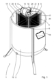
- Fig. 1 a self-turning centrifuge with four shots 4, shown in three dimensions. For reasons of clarity, the lid of container 2 in the Fig. 1 omitted.
- a rotating basket 3 is provided inside the container, which can be set in rotation about the rotation axis 6 by a drive 8, which comprises a motor 9.
- the receptacles 4 are preferably pivotally mounted on this basket, so that they assume a different position depending on the direction of rotation due to the centrifugal forces.
- the rotation axis 10 of the receptacles 4 is closer to the inner wall 14 of the container than to the rotation axis 6 of the basket 3.
- the receptacles 4 have a receiving space 5 for honeycombs 20, which are shown here in black.
- the receptacles have a grid structure so that honey can be ejected from the honeycombs 20 against the inner wall 14 of the container due to centrifugal forces, depending on the direction of rotation either from the first or the second side of the honeycomb.
- the honey then runs down the inner wall 14 of the container and can be removed from the outlet opening 12. Understandably, the weight of the honeycombs decreases, which influences the strength of the honeycomb 20 as well as a possible imbalance of the basket 3.
- At least one measuring device 17 is provided, which provides information about the weight of the honeycombs 20 and passes this measured value on to a control unit 15 of the drive 8, whereby the speed of the basket 3 can be influenced directly via the motor 9 in order to avoid damage.
- the possible damage relates on the one hand to excessive stress on the honeycombs, but primarily in this invention to the overloading of the bearings of the axis of rotation of the basket 3. Accordingly, an automatic control of the rotational speed of the basket can be set up so that a critical limit for the centrifugal force is not exceeded.
- the measuring device 17, which continuously measures the effect of an imbalance of the basket 3, can work with different physical measuring methods.
- a sensor 21 is provided for determining the moment of inertia, from whose measured value the weight of the honeycomb can be calculated.
- a force or weight sensor 18 is mounted in the holder 4, which can also transmit its measurement data wirelessly as a piezoelectric sensor, for example.
- a protractor could be provided, which determines the deflection of the holder 4 based on the centrifugal force against the force of the reset device and can therefore also display the weight.
- the deflection angle can also be determined using optoelectronic methods.
- the sensors can be calibrated to the empty basket or to the basket filled with honeycombs in the holders before a spinning process.
- the weight or mass changes of at least two or even all of the honeycombs are tracked. This makes the system more reliable and also allows for better detection of any imbalances in the basket.
- the unbalance can also be determined by detecting vibrations caused by the unbalance via at least one acceleration sensor.
- a proximity or optical sensor can be used on the basket or its axis of rotation to obtain a reference for the angular position.
- Such sensors are indicated in the figure only by a symbol with the reference number 22 and are part of a general measuring device 17.
- the measurement results are transmitted via control lines 23 to the control unit 15 in the drive 8, which controls the motor 9.
- the acceleration sensors can also be mounted directly on the frequency converter or on its electrical board.
- the absorbed voltage and frequency fluctuations can be recorded via the frequency converter 24 provided in the drive.
- a maximum speed is stored in the control unit 15 depending on the honeycomb weight or the honeycomb weight distribution.
- the operator of the honey extractor can, for example, follow the exact course of the speed change on a monitor 16.
- the monitor could also be a tablet or smartphone.
Landscapes
- Life Sciences & Earth Sciences (AREA)
- Environmental Sciences (AREA)
- Animal Husbandry (AREA)
- Biodiversity & Conservation Biology (AREA)
- Centrifugal Separators (AREA)
Priority Applications (1)
| Application Number | Priority Date | Filing Date | Title |
|---|---|---|---|
| RS20250135A RS66490B1 (sr) | 2021-04-22 | 2022-03-09 | Postupak za pražnjenje saća košnice meda i izvlačenje meda iz košnice |
Applications Claiming Priority (1)
| Application Number | Priority Date | Filing Date | Title |
|---|---|---|---|
| DE102021002118.5A DE102021002118B3 (de) | 2021-04-22 | 2021-04-22 | Verfahren zum Ausschleudern von Honigwaben und Honigschleuder |
Publications (3)
| Publication Number | Publication Date |
|---|---|
| EP4079151A1 EP4079151A1 (de) | 2022-10-26 |
| EP4079151C0 EP4079151C0 (de) | 2024-11-27 |
| EP4079151B1 true EP4079151B1 (de) | 2024-11-27 |
Family
ID=80685126
Family Applications (1)
| Application Number | Title | Priority Date | Filing Date |
|---|---|---|---|
| EP22161013.2A Active EP4079151B1 (de) | 2021-04-22 | 2022-03-09 | Verfahren zum ausschleudern von honigwaben und honigschleuder |
Country Status (7)
| Country | Link |
|---|---|
| EP (1) | EP4079151B1 (pl) |
| CN (1) | CN115226658A (pl) |
| DE (1) | DE102021002118B3 (pl) |
| ES (1) | ES2999766T3 (pl) |
| HU (1) | HUE069762T2 (pl) |
| PL (1) | PL4079151T3 (pl) |
| RS (1) | RS66490B1 (pl) |
Families Citing this family (2)
| Publication number | Priority date | Publication date | Assignee | Title |
|---|---|---|---|---|
| DE102021002125B3 (de) * | 2021-04-22 | 2022-05-05 | Groschopp Aktiengesellschaft Drives & More | Verfahren zum Ausschleudern von Honigwaben und Honigschleuder |
| EP4342588A1 (de) * | 2022-09-22 | 2024-03-27 | Siemens Aktiengesellschaft | Verfahren und vorrichtung zur überwachung einer zentrifuge |
Family Cites Families (14)
| Publication number | Priority date | Publication date | Assignee | Title |
|---|---|---|---|---|
| DE729635C (de) * | 1937-03-28 | 1942-12-19 | Christian Graze | Honigschleuder |
| CH242537A (de) * | 1945-03-05 | 1946-05-31 | Maag Hermann | Selbstwende-Honigschleuder. |
| DE7822554U1 (de) | 1978-07-27 | 1978-11-02 | Fa. Heinrich Mack Nachf. Chemisch- Pharmazeutische Fabrik, 7918 Illertissen | Honigschleuder |
| DE8105048U1 (de) | 1981-02-24 | 1981-08-13 | Christian Graze KG Fabrik für Bienenzuchtgeräte und Möbel in Endersbach, 7056 Weinstadt | "sicherheitsvorrichtung fuer elektrisch betriebene honigschleudern" |
| DE8708266U1 (de) * | 1987-06-11 | 1987-08-13 | Walter Sarstedt Kunststoff-Spritzgußwerk, 5223 Nümbrecht | Vorrichtung zum Ermitteln der Unwucht eines Rotors |
| DE19539633C2 (de) * | 1995-10-25 | 1998-06-04 | Heraeus Instr Gmbh & Co Kg | Verfahren zur Ermittlung einer Unwucht eines mittels einer Antriebseinrichtung in Drehung versetzten Rotors einer Zentrifuge und Vorrichtung zur Durchführung des Verfahrens |
| US6063292A (en) * | 1997-07-18 | 2000-05-16 | Baker Hughes Incorporated | Method and apparatus for controlling vertical and horizontal basket centrifuges |
| AU2810201A (en) * | 2000-03-20 | 2001-09-27 | Maher Omar Amin | Multi-layered honey extractors |
| EP1925706A1 (en) * | 2006-11-23 | 2008-05-28 | Electrolux Home Products Corporation N.V. | Unbalance control system for vertical-rotation-axis washing machines |
| WO2016008755A1 (de) * | 2014-07-17 | 2016-01-21 | Gea Mechanical Equipment Gmbh | Verfahren zum regeln des betriebs einer zentrifuge |
| WO2018106097A1 (es) | 2016-12-08 | 2018-06-14 | Xnox S.A. De C.V. | Extractor de miel que no genera espuma |
| CN107996462B (zh) * | 2017-11-30 | 2020-11-10 | 合肥道正数据科技有限公司 | 一种自动摇蜜机 |
| DE202019004827U1 (de) | 2019-11-27 | 2020-01-09 | Manfred Heinl | Mobiler umweltfreundlicher Bienenwaben-Schleuderwagen |
| CN112450130B (zh) * | 2020-11-25 | 2023-03-17 | 山东科技大学 | 一种智能自动采蜜、检测、分装系统及工作方法 |
-
2021
- 2021-04-22 DE DE102021002118.5A patent/DE102021002118B3/de active Active
-
2022
- 2022-03-09 EP EP22161013.2A patent/EP4079151B1/de active Active
- 2022-03-09 HU HUE22161013A patent/HUE069762T2/hu unknown
- 2022-03-09 ES ES22161013T patent/ES2999766T3/es active Active
- 2022-03-09 PL PL22161013.2T patent/PL4079151T3/pl unknown
- 2022-03-09 RS RS20250135A patent/RS66490B1/sr unknown
- 2022-04-21 CN CN202210424851.3A patent/CN115226658A/zh active Pending
Also Published As
| Publication number | Publication date |
|---|---|
| DE102021002118B3 (de) | 2022-05-05 |
| ES2999766T3 (en) | 2025-02-26 |
| EP4079151A1 (de) | 2022-10-26 |
| PL4079151T3 (pl) | 2025-03-17 |
| CN115226658A (zh) | 2022-10-25 |
| EP4079151C0 (de) | 2024-11-27 |
| RS66490B1 (sr) | 2025-03-31 |
| HUE069762T2 (hu) | 2025-04-28 |
Similar Documents
| Publication | Publication Date | Title |
|---|---|---|
| EP4079151B1 (de) | Verfahren zum ausschleudern von honigwaben und honigschleuder | |
| EP0649931B1 (de) | Verfahren zum Bestimmen der Masse von nasser Wäsche in einer Wäschetrommel | |
| DE2748615C2 (de) | Verfahren zum Entölen, Rommeln, Waschen und Trocknen insbesondere von Gegenständen mit Sacklöchern und Zentrifuge zur Durchführung des Verfahrens | |
| DE602004011785T2 (de) | Verfahren und Vorrichtung zur Messung einer Gleichförmigkeit von Reifen | |
| WO2012035073A1 (de) | Magnusrotor mit auswuchtgewichten und verfahren zum auswuchten eines rotationskörpers | |
| DE102011100044B4 (de) | Sensoranordnung zur Identifikation eines in eine Zentrifuge eingesetzten Rotors und Zentrifuge | |
| EP3009539B1 (de) | Ballenöffner | |
| DE102012201717A1 (de) | Probenträger-Zentrifuge | |
| EP1111117B1 (de) | Verfahren zum Positionieren einer Waschtrommel einer Waschmaschine in einer Zielposition | |
| EP1760186A2 (de) | Verfahren und Vorrichtung zum Waschen und/oder Schleudern von Wäsche | |
| DE102021002125B3 (de) | Verfahren zum Ausschleudern von Honigwaben und Honigschleuder | |
| DE3812330A1 (de) | Verfahren zur messung der waescheverteilung, insbesondere bei waschmaschinen und waescheschleudern | |
| EP2771122A1 (de) | Verfahren zum automatischen beladen einer zentrifuge mit probenbehältern | |
| WO2007134926A1 (de) | Verfahren zur ermittlung bzw. verringerung einer unwucht bei einer maschine zum waschen und/oder trocknen von wäsche | |
| DE102021002123B3 (de) | Honigschleuder | |
| DE20307913U1 (de) | Vorrichtung zur Konzentration von Stoffgemischen | |
| EP1927688A1 (de) | Lagerung von Spindelanordnungen in Ringspinnmaschinen mit Einzelspindelantrieb | |
| EP4079152A1 (de) | Honigschleuder | |
| DE202006006648U1 (de) | Korbwickler für Metalldraht | |
| DE69200246T2 (de) | Auf einer Trägheitsplatte abgestützte Rotationsmaschine. | |
| DE2612911C3 (de) | Vorrichtung zur Prüfung von Wälzlagern | |
| DE19653377B4 (de) | Schubzentrifuge | |
| DE3809534C2 (de) | Verfahren und Vorrichtung zur Korrektur der Fallbahn des Beschickungsgutes in einer Schachtofen-Beschickungsanlage | |
| EP0024025B1 (de) | Gussschleuder | |
| DE888020C (de) | Zentrifuge zum Schleudern von Fluessigkeitsproben |
Legal Events
| Date | Code | Title | Description |
|---|---|---|---|
| PUAI | Public reference made under article 153(3) epc to a published international application that has entered the european phase |
Free format text: ORIGINAL CODE: 0009012 |
|
| STAA | Information on the status of an ep patent application or granted ep patent |
Free format text: STATUS: THE APPLICATION HAS BEEN PUBLISHED |
|
| AK | Designated contracting states |
Kind code of ref document: A1 Designated state(s): AL AT BE BG CH CY CZ DE DK EE ES FI FR GB GR HR HU IE IS IT LI LT LU LV MC MK MT NL NO PL PT RO RS SE SI SK SM TR |
|
| STAA | Information on the status of an ep patent application or granted ep patent |
Free format text: STATUS: REQUEST FOR EXAMINATION WAS MADE |
|
| 17P | Request for examination filed |
Effective date: 20230420 |
|
| RBV | Designated contracting states (corrected) |
Designated state(s): AL AT BE BG CH CY CZ DE DK EE ES FI FR GB GR HR HU IE IS IT LI LT LU LV MC MK MT NL NO PL PT RO RS SE SI SK SM TR |
|
| GRAP | Despatch of communication of intention to grant a patent |
Free format text: ORIGINAL CODE: EPIDOSNIGR1 |
|
| STAA | Information on the status of an ep patent application or granted ep patent |
Free format text: STATUS: GRANT OF PATENT IS INTENDED |
|
| INTG | Intention to grant announced |
Effective date: 20240626 |
|
| GRAS | Grant fee paid |
Free format text: ORIGINAL CODE: EPIDOSNIGR3 |
|
| GRAA | (expected) grant |
Free format text: ORIGINAL CODE: 0009210 |
|
| STAA | Information on the status of an ep patent application or granted ep patent |
Free format text: STATUS: THE PATENT HAS BEEN GRANTED |
|
| AK | Designated contracting states |
Kind code of ref document: B1 Designated state(s): AL AT BE BG CH CY CZ DE DK EE ES FI FR GB GR HR HU IE IS IT LI LT LU LV MC MK MT NL NO PL PT RO RS SE SI SK SM TR |
|
| REG | Reference to a national code |
Ref country code: GB Ref legal event code: FG4D Free format text: NOT ENGLISH |
|
| REG | Reference to a national code |
Ref country code: CH Ref legal event code: EP |
|
| REG | Reference to a national code |
Ref country code: DE Ref legal event code: R096 Ref document number: 502022002202 Country of ref document: DE |
|
| REG | Reference to a national code |
Ref country code: IE Ref legal event code: FG4D Free format text: LANGUAGE OF EP DOCUMENT: GERMAN |
|
| U01 | Request for unitary effect filed |
Effective date: 20241204 |
|
| U07 | Unitary effect registered |
Designated state(s): AT BE BG DE DK EE FI FR IT LT LU LV MT NL PT RO SE SI Effective date: 20241213 |
|
| REG | Reference to a national code |
Ref country code: SK Ref legal event code: T3 Ref document number: E 45664 Country of ref document: SK Ref country code: ES Ref legal event code: FG2A Ref document number: 2999766 Country of ref document: ES Kind code of ref document: T3 Effective date: 20250226 |
|
| PG25 | Lapsed in a contracting state [announced via postgrant information from national office to epo] |
Ref country code: HR Free format text: LAPSE BECAUSE OF FAILURE TO SUBMIT A TRANSLATION OF THE DESCRIPTION OR TO PAY THE FEE WITHIN THE PRESCRIBED TIME-LIMIT Effective date: 20241127 Ref country code: IS Free format text: LAPSE BECAUSE OF FAILURE TO SUBMIT A TRANSLATION OF THE DESCRIPTION OR TO PAY THE FEE WITHIN THE PRESCRIBED TIME-LIMIT Effective date: 20250327 |
|
| PGFP | Annual fee paid to national office [announced via postgrant information from national office to epo] |
Ref country code: HU Payment date: 20250131 Year of fee payment: 4 |
|
| PG25 | Lapsed in a contracting state [announced via postgrant information from national office to epo] |
Ref country code: NO Free format text: LAPSE BECAUSE OF FAILURE TO SUBMIT A TRANSLATION OF THE DESCRIPTION OR TO PAY THE FEE WITHIN THE PRESCRIBED TIME-LIMIT Effective date: 20250227 |
|
| PG25 | Lapsed in a contracting state [announced via postgrant information from national office to epo] |
Ref country code: GR Free format text: LAPSE BECAUSE OF FAILURE TO SUBMIT A TRANSLATION OF THE DESCRIPTION OR TO PAY THE FEE WITHIN THE PRESCRIBED TIME-LIMIT Effective date: 20250228 |
|
| PGFP | Annual fee paid to national office [announced via postgrant information from national office to epo] |
Ref country code: PL Payment date: 20250303 Year of fee payment: 4 |
|
| PGFP | Annual fee paid to national office [announced via postgrant information from national office to epo] |
Ref country code: SK Payment date: 20250124 Year of fee payment: 4 |
|
| REG | Reference to a national code |
Ref country code: HU Ref legal event code: AG4A Ref document number: E069762 Country of ref document: HU |
|
| PGFP | Annual fee paid to national office [announced via postgrant information from national office to epo] |
Ref country code: RS Payment date: 20250210 Year of fee payment: 4 |
|
| U20 | Renewal fee for the european patent with unitary effect paid |
Year of fee payment: 4 Effective date: 20250325 |
|
| PG25 | Lapsed in a contracting state [announced via postgrant information from national office to epo] |
Ref country code: SM Free format text: LAPSE BECAUSE OF FAILURE TO SUBMIT A TRANSLATION OF THE DESCRIPTION OR TO PAY THE FEE WITHIN THE PRESCRIBED TIME-LIMIT Effective date: 20241127 |
|
| PGFP | Annual fee paid to national office [announced via postgrant information from national office to epo] |
Ref country code: ES Payment date: 20250428 Year of fee payment: 4 |
|
| PG25 | Lapsed in a contracting state [announced via postgrant information from national office to epo] |
Ref country code: CZ Free format text: LAPSE BECAUSE OF FAILURE TO SUBMIT A TRANSLATION OF THE DESCRIPTION OR TO PAY THE FEE WITHIN THE PRESCRIBED TIME-LIMIT Effective date: 20241127 |
|
| PLBE | No opposition filed within time limit |
Free format text: ORIGINAL CODE: 0009261 |
|
| STAA | Information on the status of an ep patent application or granted ep patent |
Free format text: STATUS: NO OPPOSITION FILED WITHIN TIME LIMIT |
|
| REG | Reference to a national code |
Ref country code: CH Ref legal event code: L10 Free format text: ST27 STATUS EVENT CODE: U-0-0-L10-L00 (AS PROVIDED BY THE NATIONAL OFFICE) Effective date: 20251008 |
|
| PG25 | Lapsed in a contracting state [announced via postgrant information from national office to epo] |
Ref country code: MC Free format text: LAPSE BECAUSE OF FAILURE TO SUBMIT A TRANSLATION OF THE DESCRIPTION OR TO PAY THE FEE WITHIN THE PRESCRIBED TIME-LIMIT Effective date: 20241127 |
|
| REG | Reference to a national code |
Ref country code: CH Ref legal event code: H13 Free format text: ST27 STATUS EVENT CODE: U-0-0-H10-H13 (AS PROVIDED BY THE NATIONAL OFFICE) Effective date: 20251023 |
|
| 26N | No opposition filed |
Effective date: 20250828 |