EP4077794B1 - Machine for automatically feeding flatwork articles - Google Patents
Machine for automatically feeding flatwork articles Download PDFInfo
- Publication number
- EP4077794B1 EP4077794B1 EP20824288.3A EP20824288A EP4077794B1 EP 4077794 B1 EP4077794 B1 EP 4077794B1 EP 20824288 A EP20824288 A EP 20824288A EP 4077794 B1 EP4077794 B1 EP 4077794B1
- Authority
- EP
- European Patent Office
- Prior art keywords
- grippers
- delivery
- reception
- corner
- article
- Prior art date
- Legal status (The legal status is an assumption and is not a legal conclusion. Google has not performed a legal analysis and makes no representation as to the accuracy of the status listed.)
- Active
Links
Images


Classifications
-
- D—TEXTILES; PAPER
- D06—TREATMENT OF TEXTILES OR THE LIKE; LAUNDERING; FLEXIBLE MATERIALS NOT OTHERWISE PROVIDED FOR
- D06F—LAUNDERING, DRYING, IRONING, PRESSING OR FOLDING TEXTILE ARTICLES
- D06F67/00—Details of ironing machines provided for in groups D06F61/00, D06F63/00, or D06F65/00
- D06F67/04—Arrangements for feeding or spreading the linen
-
- D—TEXTILES; PAPER
- D06—TREATMENT OF TEXTILES OR THE LIKE; LAUNDERING; FLEXIBLE MATERIALS NOT OTHERWISE PROVIDED FOR
- D06F—LAUNDERING, DRYING, IRONING, PRESSING OR FOLDING TEXTILE ARTICLES
- D06F67/00—Details of ironing machines provided for in groups D06F61/00, D06F63/00, or D06F65/00
- D06F67/10—Driving arrangements
-
- B—PERFORMING OPERATIONS; TRANSPORTING
- B65—CONVEYING; PACKING; STORING; HANDLING THIN OR FILAMENTARY MATERIAL
- B65H—HANDLING THIN OR FILAMENTARY MATERIAL, e.g. SHEETS, WEBS, CABLES
- B65H2406/00—Means using fluid
- B65H2406/30—Suction means
- B65H2406/31—Suction box; Suction chambers
-
- B—PERFORMING OPERATIONS; TRANSPORTING
- B65—CONVEYING; PACKING; STORING; HANDLING THIN OR FILAMENTARY MATERIAL
- B65H—HANDLING THIN OR FILAMENTARY MATERIAL, e.g. SHEETS, WEBS, CABLES
- B65H2701/00—Handled material; Storage means
- B65H2701/10—Handled articles or webs
- B65H2701/17—Nature of material
- B65H2701/174—Textile; fibres
-
- D—TEXTILES; PAPER
- D06—TREATMENT OF TEXTILES OR THE LIKE; LAUNDERING; FLEXIBLE MATERIALS NOT OTHERWISE PROVIDED FOR
- D06F—LAUNDERING, DRYING, IRONING, PRESSING OR FOLDING TEXTILE ARTICLES
- D06F95/00—Laundry systems or arrangements of apparatus or machines; Mobile laundries
Definitions
- the present invention generally relates to a machine for automatically feeding flatwork articles, that is laminar cloth articles such a quadrangular bed sheet to a subsequent article cloth processing machine such as an ironer-dryer machine.
- EP 3578702A1 refers to a cloth spreading apparatus capable of lessening burden of the operators and reducing operation time, the apparatus comprising several cloth loading posts and for each of them a pair of feeding clamps, a moving device for moving the pair of feeding clamps between a feeding position where adjacent corners of a cloth are manually placed into the feeding clamps by an operator and a delivery position of the cloth and a spreading clamps for directly or indirectly receiving the cloth from the pair of feeding clamps and spreading the cloth in a direction of separating the adjacent corners from each other, wherein the moving device has a separate moving trajectory corresponding to each of the feeding clamps and the pair of feeding chucks are constructed so as to move independently of each other between the feeding position and the delivery position.
- WO 9603540A2 (Chicago Dryer ) discloses an apparatus for feeding flatwork articles to an outgoing feed conveyor, including a transfer mechanism to grip a leading-edge portion of a flatwork article between leading corner portions thereof and move the article from a loading station to a pickup station.
- a positioning device is provided to locate a trailing edge portion of the article at the pickup station for engagement with a moving mechanism, that grips said trailing edge portion of the article moving the article to a pickup station provided with spreading grippers, the outgoing feed conveyor having a front end located below the spreading grippers and a conveying surface movable in the feed direction to transfer the flatwork article to into an ironer.
- the solution described in the WO 9603540A2 by automatically locating the trailing corner portions of the sheet for pickup by a moving mechanism, an operator loading the flatwork article such as a bed sheet does not have to locate the side edge or the corner portions thereof. Moreover, the operator does not have to manually clamp the corner portions directly to a pair of clamps or locate and press a conventional button or the like to initiate processing of the sheet. Thus, a simple, compact loading and transferring apparatus is provided which increases the speed at which a single operator can load sheets for accurate placement onto a feed conveyor.
- EP1683908 (Institut Jean Michel ) describes a device for transferring laundry to server clamps where two loaders move around a horizontal axis to a transfer position in the area where the laundry is tensioned.
- the apparatus also includes a suction device having a suction mouth adjacent to a lower part of the reception end of a conveyor belt to attract the flat article of clothing by means of a suction jet towards said reception end of the conveyor belt and towards a longitudinal introducer roller located next to a lower edge of said suction mouth.
- Said longitudinal roller is driven to rotate so as to cooperate with the suction device and quickly drag the hanging part of the article of clothing into a box of the device from where the article of clothing is dragged by the conveyor belt while mobile brushes moving longitudinally in divergent directions next to the suction mouth remove any possible wrinkles from the article of clothing.
- EP3301218A1 (Kannegiesser ) describes a laundry engagement device and corner search based on a similar technical principle as WO 9603540 .
- protruding corner portions of the flatwork textile articles are usually formed at one side of a clamping pinch of the spreading clamps. Said protruding corner portions primarily give rise to so-called ear formations when the front edge of the flatwork textile article is stretched by the spreading clamps. Said ear formations negatively impact the quality of the flatwork textile article once transferred to the outgoing feed conveyor.
- WO2018059730A1 Korean a mechanism of rollers included in the clamps of a positioning device as disclosed in WO 9603540 to move the respective corner region of the laundry within the clamp so that the flatwork article is gripped by points close to the corners.
- Patent application EP3663458A1 discloses an alternative mechanism wherein the clamping members are a pair of clamp assemblies coupled to the transverse guides and arranged to grasp corner portions of two contiguous corners of the flatwork textile article delivered thereto, and driving elements operatively connected to move the clamp assemblies along the transverse guides in opposite directions to spread the flatwork textile article in order to deposit it on an outgoing feed conveyor.
- All the devices and apparatus of the referred antecedents where it is not necessary for an operator to manually arrange the corners into clamps at the loading posts have gripper systems that come to pick up the corners presented by the workstation once located and transfer the flatwork articles to the spreading grippers via the centre part of the machine where the flatwork articles are centred in relation to an outgoing feed conveyor, extended and smoothed by known unwrinkling brushes.
- US20150071736 discloses a method of transferring a piece of cloth and a laundry apparatus for performing the method in which a vacuum boom being divided into two or more sections that are connected to each other by means of hinges and are carried and controlled by mechanisms configured therefor.
- the present patent application proposes a machine with a plurality of loading posts each of them including a load conveyor configured to transfer a leading-edge portion of a flatwork article between leading corner portions thereof to a rear delivery unit including a location mechanism to locate trailing corner portions of the flatwork article according to the state of the art for example as disclosed in WO9603540A2 , but simplifying the transfer of the flatwork articles to the spreading grippers and speeding up this transfer.
- each of the loading posts has one pair of transferring grippers associated to the respective rear delivery unit and therefore the spreading grippers receive the laundry in front of each loading station from the transferring grippers and then can expand it in the centre or in a lateral area with regard to an outgoing feed conveyor, i. e. they can operate in one or more lanes.
- a suction mouth and introducer roller extends all along the outgoing feed conveyor and have associated at least two movable elements that temporally prevent the insertion of a spread piece of clothing hanging from the transferring grippers or from the spreading grippers into the suction mouth.
- the present invention contributes to overcome the above and other drawbacks by providing a feeding machine for feeding quadrangular flatwork articles such a bed sheet to a subsequent article treatment machine, wherein the feeding machine includes in accordance with the state of the art, for example as disclosed by cited WO9603540 , following elements:
- the spreading grippers are mobile independently of each other over the entire width of the transverse horizontal guide, so that they can spread a flatwork article at several different zones with regard to the outgoing feed conveyor into which the flatwork article is to be deposited.
- the flatwork article can be centred in correspondence with a central zone of the outgoing feed conveyor or in correspondence with one lateral zone thereof, allowing to operate in one or more lanes.
- the spreading grippers comprises three or more grippers independent of each other. As each of the posts includes its own transferring gripers, this allows the grippers to access the different loading post more quickly and to pick up the flatwork articles from different loading post and download them to the outgoing feed conveyor in a more efficient way.
- the suction entrance of the vacuum chamber extends all along the outgoing feed conveyor and has associated thereof two or more movable separating blades that temporally prevent the insertion of a spread flatwork article such as piece of clothing, into the suction entrance, in correspondence with any of the above-mentioned several different zones, where the unloading of the flatwork articles can take place towards the conveying surface of the outgoing feed conveyor.
- the machine includes a controller that coordinates the movements of the transferring grippers, spreading grippers and movable separating blades.
- FIG. 1 Further aspects of the invention concern to an introducer roller arranged parallel to the front end of the outgoing feed conveyor and adjacent the suction entrance of the vacuum chamber, the introducer roller extending all along the whole outgoing feed conveyor width and being rotated by a motor in a load direction by which an uncovered upper surface of the introducer roller moves towards the suction entrance so that when a portion of the flatwork article suspended in the spreading grippers contacts with upper surface of the introducer roller is dragged toward the suction entrance.
- each separating blade is moved in a vertical direction upwardly to position itself between the flatwork article and the introducer roller in order to prevent contact between these two elements during a first step of transfer of the flatwork article towards the outgoing feed conveyor and that moves downward in a second step of the transfer when the flatwork article is to be transferred so that a free end portion of the spread flatwork article encounters the introducer roller and enters the vacuum chamber.
- An actuator provides these up and down movements of the separating blade.
- the vacuum chamber further includes a member driven by an actuator that temporally reduces the suction in the vacuum chamber obstructing substantially the vacuum chamber section.
- the cited controller provides a synchronisation between movements of each separating blade and member to temporally reduce u obstruct the suction in the vacuum chamber, and further provides a coordination between the movement of the different separating blades to operate separately or to operate in conjunction depending on the zone where the flatwork article is centred.
- the feeding machine of this invention is further equipped with an auxiliary device placed in superposition to the loading end of outgoing feed conveyor including a roof plate configured to be driven away from the surface of the feed conveyor or close to it allowing a controlled passage of the flat clothing article extended on said outgoing feed conveyor, as known by EP2977505A1 of the same applicant, but in this embodiment the auxiliary device extending transverse to the loading direction of the flatwork article on said outgoing feed conveyor and being divided in two independent parts, each of said parts having own driving means, in correspondence with the two movable separating blades.
- the cited controller further provides a synchronisation between movements of each separate blade and independent parts of the auxiliary device, so that contributing to operate alternately in one or more lanes and allow to deposit the flatwork article on one half or the other half of the outgoing conveyor.
- the transfer system of each loading station comprises one pair of transferring grippers wherein jaws of each transferring gripper are mounted on a pivot arm pivotable about a pivot axis, the pivot axes being parallel to each other determining that movement of both pivot arms are coplanar, and the transferring grippers describe circular arc paths in opposite directions when moving between a receiving position below corner-gripping nip rollers that retain end portions of a bed sheet and a transfer position. These circular arc paths determine that the gripped portions of the flatwork article are moved away, i.e., the piece of clothing is transversally extended a certain degree while it is transferred.
- pivot axis of the jaws of each transferring gripper is oriented in a vertical direction and the circular arc paths described by the transferring grippers when moving between the receiving position and the transfer position are comprised in a horizontal plane.
- the machine further includes two corner-detecting sensors each arranged so as to detect the presence of a rear corner of a flatwork article in a space adjacent gripping nip rollers.
- the outgoing feed conveyor has a feed conveyor width greater than the load conveyor width of each loading post and the transverse horizontal guide has a guide length equal or greater than the outgoing feed conveyor width.
- the reference sign 100 generally designates a feeding machine intended for feeding quadrangular flatwork articles 53 such as bed sheets to a subsequent cloth processing machine such as an ironing-dryer machine (an outgoing feed conveyor 9 of said subsequent cloth processing machine is shown in Figs. 1 , 7 , 11a to 11c ).
- the feeding machine 100 includes three loading post 1 for loading for example, quadrangular bed sheets manually introduced at a front reception area of each loading post by an operator gripping a leading-edge portion of the bed sheet between leading corner portions thereof.
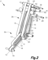
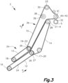
- Figs 2 and 3 show a diagrammatic perspective and a side views, respectively, of the load conveyor 2 that consist of two parts, a front reception unit 2a and a rear delivery unit 2b.
- the front reception unit 2a comprises a lower reception endless belt 12 extending around a horizontal lower reception front pulley 16 and a horizontal lower reception rear pulley 17; and an upper reception shorter endless belt 13 extending around a horizontal upper reception front pulley 18 and a horizontal upper reception rear pulley 19. The leading edge of a bed sheet is conveyed clamped between the lower reception endless belt 12 and the upper reception endless belt 13
- the rear delivery unit 2b comprises two lower delivery endless belts 14 extending around respective horizontal lower delivery front pulleys 20 and respective horizontal lower delivery rear pulleys 21, and two upper delivery endless belts 15 extending around respective horizontal upper delivery front pulleys 22 and respective horizontal upper delivery rear pulleys 23, the lower delivery rear pulleys 21 are at a higher level than the lower delivery front pulleys 20 and the upper delivery front pulleys 22.
- Each lower delivery endless belt 14 is paired with one of the upper delivery endless belts 15 and both have respective drag sections which continue to clamp the leading edge of the bed sheet and said drag sections facing each other and move in the feed direction D.
- the pairs of lower and upper delivery endless belts 14, 15 are located at either sides of the pair of lower and upper reception endless belts 12, 13; and the lower delivery front pulleys 20 are coaxial with the lower reception rear pulley 17 and the upper delivery front pulleys 22 are coaxial with the upper reception rear pulley 19.
- the lower reception rear pulley 17 and the lower delivery front pulleys 20 are rigidly attached to a lower front shaft 27, the lower delivery rear pulleys 21 are rigidly attached to a lower rear shaft 28.
- the horizontal upper reception rear pulley 19 and the upper delivery front pulleys 22 are rigidly attached to an upper front shaft 29.
- the upper delivery rear pulleys 23 are rigidly attached to an upper rear shaft 30.
- Fig. 3 also show two pairs of corner-gripping nip rollers 4, 5.
- the two pairs of corner-gripping nip rollers 4, 5 have respective parallel axes which lay in a horizontal plane when the movable corner-gripping nip roller 5 is in the grip position.
- Fig. 3A is a partial detail of upper region of Fig. 3 , with the addition of the transferring grippers 6 and the spreading grippers 7 of the pickup station that are slidable mounted on a transversal guide 8.
- the figure also shows a hood 70 covering the rear delivery unit 2b which can be raised or lowered with for example a piston 72.
- Fig. 3A Also shown in this Fig. 3A is one of the two corner-detecting sensors 43, each arranged so as to detect the presence of a rear corner of a bed sheet in a space adjacent gripping roller 4.
- Figs 4A and 4B show a movable corner-gripping roller 5 parallel to the stationary corner-gripping roller 4 and rotary mounted on a roller shaft 32 fixed to a pivot arm 33 pivotally mounted on a pivot shaft 34.
- the stationary corner-gripping roller 4 is located adjacent to one of the lower delivery rear pulleys 21 of the rear delivery unit 26 and rotary mounted on the lower rear shaft 28.
- the Figs. 4A and 4B also show one single nip roller motor 35 that is operatively connected to rotate the stationary and movable corner-gripping rollers 4, 5 of each pair of corner-gripping nip rollers 4, 5 in opposite directions; and an arm actuator 36 is operatively connected to move the pivot arm 33 of each pair of corner-gripping nip rollers 4, 5 between a grip position ( Fig. 4A ), in which the movable corner-gripping roller 5 presses against the stationary corner-gripping roller 4, and a release position ( Fig. 4B ), in which the movable corner-gripping roller 5 is away from the stationary corner-gripping roller 4.
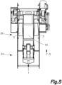
- Fig. 5 is a front view of one of the loading posts showing a loading post 1 having a load conveyor comprising a conveying surface movable in a feed direction D, a front reception unit 2a and a rear delivery unit 2b.
- the loading post further comprises one pair of side guiding channels 3 for the lateral parts of the sheet, which hang hanging, the channels 3 being located on each side of the rear delivery unit 2b of the load conveyor 2, and the guiding channels 3 having respective rear delivery ends.
- Figs. 6A and 6B are diagrammatic partial side views of the front reception unit 2a of the load conveyor 2 in two different tilt positions thereof comprising a spring element 55 operatively connected to the lower tilting support 54 to bias the lower tilting support 54 to rotate upwards, the lower tilting support 54 being lockable in a desired tilt position by a locking device;
- Figs. 6A and 6B also show the upper reception front pulley 18 that is mounted on an upper tilting support 56 pivotable about an axis coaxial with the upper reception rear pulley 19, the drag section of the upper reception endless belt 13 resting on the drag section of the lower reception endless belt 12 by gravity at any tilt position of the lower tilting support 54.
- the spring element 55 is embodied as a gas spring cylinder including the locking device therein, the locking device being manually operable by a lever 57.
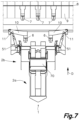
- Fig. 7 shows a partial schematic top view of the loading post 1 of the Fig. 5 with elimination of a part of the hood 70 of the upper part; this view shows one pair of transferring grippers 6 movable between a receiving position and a transfer position spaced apart from the receiving position in the feed direction D, the transferring grippers 6 having jaws movable between open and closed positions.
- Fig. 7 also illustrates one pair of spreading grippers 7 at the pickup station located at the pickup station that are movable arranged along one transverse horizontal guide 8 perpendicular to the feed direction D between a waiting position adjacent to the transfer position of the transferring grippers 6 and a spread position in which the spreading grippers 7 are more apart from each other, the spreading grippers 7 having jaws movable between open and closed positions.
- a third spreading gripper 7 has been indicated, located between the two spreading grippers 7, and this third spreading gripper is designed to operate with any one of the two other grippers in such a way that two pairs of grippers 7- operate by assisting at a given moment one of the right or left post loading or the central loading post and the other gripper 7 which is free, it enters to operate with the nearest gripper as soon as this last one has released a flatwork article.
- the third gripper or in other embodiments a four gripper will be movable arranged along one or more transverse horizontal guides 8.
- An outgoing feed conveyor 9 having a front end is located below the spreading grippers 7 and has a conveying surface movable in the feed direction D.
- each transferring gripper 6 are mounted on a pivot arm 10 pivotable about a pivot axis 11 and arranged to describe circular arc paths in opposite directions when moving between the receiving position and the transfer position due to the action of pneumatic cylinder 51. This means that when the flatwork article or flatwork article 53 held by two of its corners by the transferring grippers is transferred, those corners move away from each other, and the sheet is presented to the spreading grippers in a partially extended form.
- the pivot axles 11 for the transferring grippers 6 are vertical and the movement of both pivot arms 10 occur in a common horizontal plane i.e., the circular arc paths described by the transferring grippers 6 when moving between the receiving position and the transfer position are comprised in a horizontal plane. As previously indicated, this determine that the gripped portions of the flatwork article 53 are moved away, i.e., the piece of clothing is transversally extended a certain degree while it is transferred and when it is delivered to the spreading grippers 7.
- Fig. 8 is a partial perspective view of the transferring grippers 6 of the loading station and the spreading grippers 7 at the pickup position, with the transferring grippers 6 in a receiving position having a flatwork article 53 grabbed by two of its corners.
- Fig. 9 is a partial perspective view of the transferring grippers 6 and the spreading grippers 7, with the transferring grippers 6 in a transfer position delivering a flatwork article 53 to a pair of spreading grippers 7.
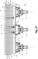
- Fig. 10 is a top plan view of an embodiment of the feeding machine 100 with three loading posts 1, where it can be seen three spreading grippers 7 and the outgoing feed conveyor 9, with each loading post 1 having the corresponding pair of transferring grippers 6 and one of the loading posts 1that is in the transfer stage of a flatwork article 53 to the spreading grippers 7.
- the spreading grippers 7, in this example in number of three, are independent of each other, and each of the spreading grippers 7 is attached to a continuous belt 61, 62, 70 rotatable around end pulleys 65, 66, 72 and each of the belts 61, 62, 70 being rotated by a respective motor M1, M2, M3, the continuous belts 61, 62, 70 extending parallel to the transversal guide 8.
- suction entrance 45 of the vacuum chamber 44 extends all along the outgoing feed conveyor and in front of the suction entrance (45) two movable separating blades 59 are located, intended as previously explained to temporally prevent insertion of a spread piece of clothing placed before one of the separation blades, into the suction entrance 45.
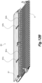
- Figs 11A to 11C are diagrammatic sectional side views of the feeding machine 100 in two different moments of bed sheet spread and unwrinkling operations, the last one intended for avoiding wrinkles on the bed sheet spread between two spreading grippers 7.
- Figs. 11A to 11C show a vacuum chamber 44 that is provided below the spreading grippers 7 and at a lower level than the outgoing feed conveyor 9 and at a distance of a leading edge of said outgoing feed conveyor 9, the vacuum chamber 44 having an entrance 45 facing the front end of the outgoing feed conveyor 9. Both the vacuum chamber 44 and the suction entrance 45 extend all along the outgoing feed conveyor 9 width, and the vacuum chamber 44 is fluidly connected to a vacuum device (not illustrated).
- the figures 11A to 11C also show an introducer or swallow roller 46 parallel to the front end of the outgoing feed conveyor 9 that is arranged in front of the suction entrance 45, the introducer roller 46 extending all along the whole outgoing feed conveyor width and being rotated by a motor in a load direction by which an uncovered upper surface of the introducer roller 46 moves towards the suction entrance 45.
- f igures 11 A to 11 C also illustrate another element of the disclosed embodiment concerning a separator blade 59, movable by an actuator 60 in a lifting and lowering motion, the separator blade being operative during the period of time in which a flatwork article 53 is transferred from the spreading grippers 7 onto the outgoing feed conveyor 9.
- a flatwork article 53 enters the vacuum chamber 44 by contact with the rotating or introducer roller 46, positioned in front of the vacuum chamber 44.
- a flatwork article 53 must be hung and stretched out outside the vacuum chamber 44.
- a separating blade 59 moves vertically to position itself between the bed sheet and the introducer roller 47 ( Fig. 11A ) in order to prevent contact between these two elements (upper position), for example if in another section of the machine introduction of another flatwork article 53 takes place.
- the vacuum chamber is ready to receive a new flatwork article (53)
- the separating blade 59 moves downwards (low position of Fig. 11B )
- the flatwork article 53 encounters the introducer roller 46 and enters the vacuum chamber 44.
- the machine is equipped with 2 independent separating blades, each driven by 2 pneumatic cylinders 60, in order to allow work in 2 half-tracks.
- the vacuum chamber 44 further includes a member 37, actuated by a piston 24, that temporally reduces the suction in the vacuum chamber 44 obstructing part of the vacuum chamber 44 section avoiding the entrance of a flatwork article 53 or facilitating the transfer of the flatwork articles 53 onto the conveying surface of the outgoing feed conveyor 9, once the flatwork article 53 has been suctioned into the vacuum chamber (see Fig. 11C ).
- the position of the separating blades 59 and the position of the member 37 temporally prevent the insertion of a spread piece of clothing into the suction entrance 45, in correspondence with any of the above-mentioned several different zones, where the unloading of the flatwork articles 53 can take place towards the conveying surface of the outgoing feed conveyor 9.
- the member 37 obstructs vacuum chamber 44 when the separating blade 59 is in an upper position ( Fig. 11A ) blocking the access of the flatwork article 53 and once the flatwork article 53 is inside of the vacuum chamber 44, and transfer of the flatwork article 53 onto the conveying surface of the outgoing feed conveyor 9 begins and leaves free the suction when the separating blade 59 is in the lower position letting in the flatwork article.
- a controller coordinates the movements of the transferring grippers 6, spreading grippers 7, separating blades 59 and members 37 in order to enable the handling of different flatwork articles 53 in a quicker way.
- the feeding machine further includes an auxiliary device 80 arranged in superposition to the loading end of the outgoing feed conveyor 9 including a roof plate 81 with a pivotable flap articulated to one edge and configured to be driven away from the surface of the feed conveyor 9 or close to it, whereby allowing a controlled passage of the flat clothing article 53 extended on said outgoing feed conveyor 9.
- the auxiliary device 80 extends transverse to the loading direction of the flatwork article on said outgoing feed conveyor and the articulated pivotable flap is divided in two independent flaps 82a, 82b, each with its own driving means 83a, 83b (that can be implemented by pistons or lineal actuators), in correspondence with the two movable separating blades 59.
- the referred controller further provides a synchronisation between movements of each separate blade 59 and independent flaps 82a, 82b of the auxiliary device 80, allowing the machine to operate in two lanes arranged side by side.
Landscapes
- Engineering & Computer Science (AREA)
- Textile Engineering (AREA)
- Feeding Of Articles By Means Other Than Belts Or Rollers (AREA)
- Treatment Of Fiber Materials (AREA)
- Mechanical Engineering (AREA)
Applications Claiming Priority (2)
| Application Number | Priority Date | Filing Date | Title |
|---|---|---|---|
| EP19383159 | 2019-12-20 | ||
| PCT/EP2020/087026 WO2021123169A1 (en) | 2019-12-20 | 2020-12-18 | Machine for automatically feeding flatwork articles |
Publications (2)
| Publication Number | Publication Date |
|---|---|
| EP4077794A1 EP4077794A1 (en) | 2022-10-26 |
| EP4077794B1 true EP4077794B1 (en) | 2024-06-05 |
Family
ID=69185297
Family Applications (1)
| Application Number | Title | Priority Date | Filing Date |
|---|---|---|---|
| EP20824288.3A Active EP4077794B1 (en) | 2019-12-20 | 2020-12-18 | Machine for automatically feeding flatwork articles |
Country Status (6)
| Country | Link |
|---|---|
| US (1) | US12234600B2 (da) |
| EP (1) | EP4077794B1 (da) |
| CN (1) | CN115135828B (da) |
| DK (1) | DK4077794T3 (da) |
| ES (1) | ES2986735T3 (da) |
| WO (1) | WO2021123169A1 (da) |
Families Citing this family (3)
| Publication number | Priority date | Publication date | Assignee | Title |
|---|---|---|---|---|
| DE202021004460U1 (de) * | 2020-05-25 | 2024-11-22 | Jensen Denmark A/S | Wäschespreizvorrichtung |
| WO2024149877A1 (en) * | 2023-01-13 | 2024-07-18 | Jensen Denmark A/S | An apparatus for receiving and spreading out laundry items, in particular pieces of linen |
| WO2025219408A1 (en) * | 2024-04-19 | 2025-10-23 | Jensen Denmark A/S | Devices and methods for conveying laundry items |
Family Cites Families (19)
| Publication number | Priority date | Publication date | Assignee | Title |
|---|---|---|---|---|
| US3414997A (en) * | 1967-09-22 | 1968-12-10 | Ametck Inc | Suction box feeder for a flatwork ironer |
| US3553863A (en) * | 1969-06-16 | 1971-01-12 | Sheetmaster Corp | Fabric spreader |
| DE3119574C2 (de) * | 1981-05-16 | 1983-11-10 | Herbert Kannegiesser Gmbh + Co, 4973 Vlotho | Vorrichtung zum Zuführen von Wäschestücken zu einer Mangel |
| GB8402909D0 (en) * | 1984-02-03 | 1984-03-07 | Weir Henry J | Laundry feeder |
| GB8813110D0 (en) * | 1988-06-03 | 1988-07-06 | Weir Henry J | Improvements in/relating to feed mechanisms for laundry articles |
| US5515627A (en) | 1994-07-27 | 1996-05-14 | Mccabe; Stanley G. | Apparatus and method for feeding flatwork articles |
| DE60331178D1 (de) * | 2003-10-10 | 2010-03-18 | Jean Michel Soc | Vorrichtung und verfahren zum einführen von flachen kleidungsstücken in ein wäschebehandlungsaggregat |
| AU2003274131A1 (en) * | 2003-10-10 | 2005-04-27 | Societe Jean Michel | Modular device which is used load flat articles of clothing into a laundry treatment unit |
| JP2007092255A (ja) * | 2005-09-30 | 2007-04-12 | Purex:Kk | 布類展張方法および布類展張機 |
| DK176722B1 (da) * | 2007-12-17 | 2009-04-27 | Jensen Denmark As | Fremgangsmode til overf ring af et t jstykke og vaskerimaskine til ud velse af fremgangsmoden |
| CN103998678B (zh) * | 2011-10-17 | 2016-11-02 | 高达机器人公司 | 用于铺展和装载平状衣物制品的机器 |
| DE102012004463A1 (de) * | 2012-03-08 | 2013-09-12 | Herbert Kannegiesser Gmbh | Vorrichtung und Verfahren zum Zuführen von Wäschestücken zu einer Mangel oder dergleichen |
| EP2977505B1 (en) * | 2014-07-24 | 2021-02-17 | Girbau Robotics | Spreading machine comprising an auxiliary device for deposition and feeding of flat clothing articles on a conveyor belt |
| EP3426839A1 (en) * | 2016-03-11 | 2019-01-16 | Jensen Denmark A/S | An apparatus for receiving, spreading/extending and flattening |
| DE102016011675A1 (de) * | 2016-09-29 | 2018-03-29 | Herbert Kannegiesser Gmbh | Verfahren und Vorrichtung zum Zuführen von Wäschestücken zu einer Wäschebehandlungseinrichtung, insbesondere einer Mangel |
| DE102016011676A1 (de) | 2016-09-29 | 2018-03-29 | Herbert Kannegiesser Gmbh | Verfahren und Vorrichtung zum Zuführen von Wäschestücken zu einer Wäschebehandlungseinrichtung, vorzugsweise einer Mangel |
| JP6621731B2 (ja) * | 2016-12-09 | 2019-12-18 | 株式会社プレックス | 布類展張装置 |
| JP6940420B2 (ja) * | 2017-01-31 | 2021-09-29 | 株式会社プレックス | 布類展張装置 |
| EP3663458B1 (en) | 2018-12-05 | 2021-08-18 | Girbau Robotics | Feeding device and method for feeding a flatwork textile article to a laundry treatment apparatus |
-
2020
- 2020-12-18 US US17/787,349 patent/US12234600B2/en active Active
- 2020-12-18 WO PCT/EP2020/087026 patent/WO2021123169A1/en not_active Ceased
- 2020-12-18 ES ES20824288T patent/ES2986735T3/es active Active
- 2020-12-18 CN CN202080097015.8A patent/CN115135828B/zh active Active
- 2020-12-18 DK DK20824288.3T patent/DK4077794T3/da active
- 2020-12-18 EP EP20824288.3A patent/EP4077794B1/en active Active
Also Published As
| Publication number | Publication date |
|---|---|
| CN115135828B (zh) | 2025-04-08 |
| US12234600B2 (en) | 2025-02-25 |
| EP4077794A1 (en) | 2022-10-26 |
| US20230013252A1 (en) | 2023-01-19 |
| ES2986735T3 (es) | 2024-11-12 |
| CN115135828A (zh) | 2022-09-30 |
| WO2021123169A1 (en) | 2021-06-24 |
| DK4077794T3 (da) | 2024-08-19 |
Similar Documents
| Publication | Publication Date | Title |
|---|---|---|
| US7127840B2 (en) | Laundry article spreader apparatus and method | |
| EP4077794B1 (en) | Machine for automatically feeding flatwork articles | |
| EP0791094B1 (en) | Apparatus for feeding flatwork articles | |
| US5440810A (en) | Apparatus for feeding and spreading laundry articles | |
| CN109154126B (zh) | 用于将洗涤衣物供应给衣物再处理装置的方法以及设备 | |
| US10407822B2 (en) | Separator and stacker for textile articles | |
| CN110730839B (zh) | 布料展平装置 | |
| JP6940420B2 (ja) | 布類展張装置 | |
| CN111936693B (zh) | 布料抓持夹头及布料操作装置 | |
| US20080295367A1 (en) | Linen spreader apparatus and method | |
| CN111212943A (zh) | 工业洗衣系统中的用于处理亚麻物品的机器、用于操作该机器的方法以及工业洗衣系统 | |
| US8732995B2 (en) | Method and apparatus for feeding a laundry article to a mangle or the like | |
| US7827709B2 (en) | Linen spreader apparatus and method | |
| WO2006057112A1 (ja) | 布類展張搬送方法および装置 | |
| US6883258B2 (en) | Spreader apparatus and method for articles of laundry | |
| JPS6116199B2 (da) | ||
| WO2019198741A1 (ja) | 縁把持装置およびそれを備えた布類自動展開機 | |
| CN111051592B (zh) | 布料自动展开机 | |
| CN110249090A (zh) | 布料展平装置 | |
| JP2009127172A (ja) | 布類展張搬送機 | |
| HK40005799A (en) | Cloth spreading apparatus | |
| HK1243469A1 (zh) | 自动布草装料机 |
Legal Events
| Date | Code | Title | Description |
|---|---|---|---|
| STAA | Information on the status of an ep patent application or granted ep patent |
Free format text: STATUS: UNKNOWN |
|
| STAA | Information on the status of an ep patent application or granted ep patent |
Free format text: STATUS: THE INTERNATIONAL PUBLICATION HAS BEEN MADE |
|
| PUAI | Public reference made under article 153(3) epc to a published international application that has entered the european phase |
Free format text: ORIGINAL CODE: 0009012 |
|
| STAA | Information on the status of an ep patent application or granted ep patent |
Free format text: STATUS: REQUEST FOR EXAMINATION WAS MADE |
|
| 17P | Request for examination filed |
Effective date: 20220616 |
|
| AK | Designated contracting states |
Kind code of ref document: A1 Designated state(s): AL AT BE BG CH CY CZ DE DK EE ES FI FR GB GR HR HU IE IS IT LI LT LU LV MC MK MT NL NO PL PT RO RS SE SI SK SM TR |
|
| DAV | Request for validation of the european patent (deleted) | ||
| DAX | Request for extension of the european patent (deleted) | ||
| GRAP | Despatch of communication of intention to grant a patent |
Free format text: ORIGINAL CODE: EPIDOSNIGR1 |
|
| STAA | Information on the status of an ep patent application or granted ep patent |
Free format text: STATUS: GRANT OF PATENT IS INTENDED |
|
| RIC1 | Information provided on ipc code assigned before grant |
Ipc: D06F 95/00 20060101ALN20240124BHEP Ipc: D06F 67/04 20060101AFI20240124BHEP |
|
| INTG | Intention to grant announced |
Effective date: 20240212 |
|
| GRAS | Grant fee paid |
Free format text: ORIGINAL CODE: EPIDOSNIGR3 |
|
| GRAA | (expected) grant |
Free format text: ORIGINAL CODE: 0009210 |
|
| STAA | Information on the status of an ep patent application or granted ep patent |
Free format text: STATUS: THE PATENT HAS BEEN GRANTED |
|
| AK | Designated contracting states |
Kind code of ref document: B1 Designated state(s): AL AT BE BG CH CY CZ DE DK EE ES FI FR GB GR HR HU IE IS IT LI LT LU LV MC MK MT NL NO PL PT RO RS SE SI SK SM TR |
|
| P01 | Opt-out of the competence of the unified patent court (upc) registered |
Effective date: 20240426 |
|
| REG | Reference to a national code |
Ref country code: CH Ref legal event code: EP |
|
| REG | Reference to a national code |
Ref country code: DE Ref legal event code: R096 Ref document number: 602020032087 Country of ref document: DE |
|
| REG | Reference to a national code |
Ref country code: IE Ref legal event code: FG4D |
|
| REG | Reference to a national code |
Ref country code: DK Ref legal event code: T3 Effective date: 20240816 |
|
| REG | Reference to a national code |
Ref country code: NL Ref legal event code: FP |
|
| REG | Reference to a national code |
Ref country code: LT Ref legal event code: MG9D |
|
| PG25 | Lapsed in a contracting state [announced via postgrant information from national office to epo] |
Ref country code: BG Free format text: LAPSE BECAUSE OF FAILURE TO SUBMIT A TRANSLATION OF THE DESCRIPTION OR TO PAY THE FEE WITHIN THE PRESCRIBED TIME-LIMIT Effective date: 20240605 |
|
| PG25 | Lapsed in a contracting state [announced via postgrant information from national office to epo] |
Ref country code: HR Free format text: LAPSE BECAUSE OF FAILURE TO SUBMIT A TRANSLATION OF THE DESCRIPTION OR TO PAY THE FEE WITHIN THE PRESCRIBED TIME-LIMIT Effective date: 20240605 Ref country code: FI Free format text: LAPSE BECAUSE OF FAILURE TO SUBMIT A TRANSLATION OF THE DESCRIPTION OR TO PAY THE FEE WITHIN THE PRESCRIBED TIME-LIMIT Effective date: 20240605 |
|
| PG25 | Lapsed in a contracting state [announced via postgrant information from national office to epo] |
Ref country code: GR Free format text: LAPSE BECAUSE OF FAILURE TO SUBMIT A TRANSLATION OF THE DESCRIPTION OR TO PAY THE FEE WITHIN THE PRESCRIBED TIME-LIMIT Effective date: 20240906 |
|
| PG25 | Lapsed in a contracting state [announced via postgrant information from national office to epo] |
Ref country code: LV Free format text: LAPSE BECAUSE OF FAILURE TO SUBMIT A TRANSLATION OF THE DESCRIPTION OR TO PAY THE FEE WITHIN THE PRESCRIBED TIME-LIMIT Effective date: 20240605 |
|
| PG25 | Lapsed in a contracting state [announced via postgrant information from national office to epo] |
Ref country code: NO Free format text: LAPSE BECAUSE OF FAILURE TO SUBMIT A TRANSLATION OF THE DESCRIPTION OR TO PAY THE FEE WITHIN THE PRESCRIBED TIME-LIMIT Effective date: 20240905 Ref country code: LV Free format text: LAPSE BECAUSE OF FAILURE TO SUBMIT A TRANSLATION OF THE DESCRIPTION OR TO PAY THE FEE WITHIN THE PRESCRIBED TIME-LIMIT Effective date: 20240605 Ref country code: HR Free format text: LAPSE BECAUSE OF FAILURE TO SUBMIT A TRANSLATION OF THE DESCRIPTION OR TO PAY THE FEE WITHIN THE PRESCRIBED TIME-LIMIT Effective date: 20240605 Ref country code: GR Free format text: LAPSE BECAUSE OF FAILURE TO SUBMIT A TRANSLATION OF THE DESCRIPTION OR TO PAY THE FEE WITHIN THE PRESCRIBED TIME-LIMIT Effective date: 20240906 Ref country code: FI Free format text: LAPSE BECAUSE OF FAILURE TO SUBMIT A TRANSLATION OF THE DESCRIPTION OR TO PAY THE FEE WITHIN THE PRESCRIBED TIME-LIMIT Effective date: 20240605 Ref country code: BG Free format text: LAPSE BECAUSE OF FAILURE TO SUBMIT A TRANSLATION OF THE DESCRIPTION OR TO PAY THE FEE WITHIN THE PRESCRIBED TIME-LIMIT Effective date: 20240605 Ref country code: RS Free format text: LAPSE BECAUSE OF FAILURE TO SUBMIT A TRANSLATION OF THE DESCRIPTION OR TO PAY THE FEE WITHIN THE PRESCRIBED TIME-LIMIT Effective date: 20240905 |
|
| REG | Reference to a national code |
Ref country code: ES Ref legal event code: FG2A Ref document number: 2986735 Country of ref document: ES Kind code of ref document: T3 Effective date: 20241112 |
|
| REG | Reference to a national code |
Ref country code: AT Ref legal event code: MK05 Ref document number: 1692534 Country of ref document: AT Kind code of ref document: T Effective date: 20240605 |
|
| PG25 | Lapsed in a contracting state [announced via postgrant information from national office to epo] |
Ref country code: PT Free format text: LAPSE BECAUSE OF FAILURE TO SUBMIT A TRANSLATION OF THE DESCRIPTION OR TO PAY THE FEE WITHIN THE PRESCRIBED TIME-LIMIT Effective date: 20241007 |
|
| PG25 | Lapsed in a contracting state [announced via postgrant information from national office to epo] |
Ref country code: PT Free format text: LAPSE BECAUSE OF FAILURE TO SUBMIT A TRANSLATION OF THE DESCRIPTION OR TO PAY THE FEE WITHIN THE PRESCRIBED TIME-LIMIT Effective date: 20241007 |
|
| PG25 | Lapsed in a contracting state [announced via postgrant information from national office to epo] |
Ref country code: PL Free format text: LAPSE BECAUSE OF FAILURE TO SUBMIT A TRANSLATION OF THE DESCRIPTION OR TO PAY THE FEE WITHIN THE PRESCRIBED TIME-LIMIT Effective date: 20240605 |
|
| PG25 | Lapsed in a contracting state [announced via postgrant information from national office to epo] |
Ref country code: EE Free format text: LAPSE BECAUSE OF FAILURE TO SUBMIT A TRANSLATION OF THE DESCRIPTION OR TO PAY THE FEE WITHIN THE PRESCRIBED TIME-LIMIT Effective date: 20240605 |
|
| PG25 | Lapsed in a contracting state [announced via postgrant information from national office to epo] |
Ref country code: AT Free format text: LAPSE BECAUSE OF FAILURE TO SUBMIT A TRANSLATION OF THE DESCRIPTION OR TO PAY THE FEE WITHIN THE PRESCRIBED TIME-LIMIT Effective date: 20240605 Ref country code: IS Free format text: LAPSE BECAUSE OF FAILURE TO SUBMIT A TRANSLATION OF THE DESCRIPTION OR TO PAY THE FEE WITHIN THE PRESCRIBED TIME-LIMIT Effective date: 20241005 |
|
| PG25 | Lapsed in a contracting state [announced via postgrant information from national office to epo] |
Ref country code: CZ Free format text: LAPSE BECAUSE OF FAILURE TO SUBMIT A TRANSLATION OF THE DESCRIPTION OR TO PAY THE FEE WITHIN THE PRESCRIBED TIME-LIMIT Effective date: 20240605 |
|
| PG25 | Lapsed in a contracting state [announced via postgrant information from national office to epo] |
Ref country code: RO Free format text: LAPSE BECAUSE OF FAILURE TO SUBMIT A TRANSLATION OF THE DESCRIPTION OR TO PAY THE FEE WITHIN THE PRESCRIBED TIME-LIMIT Effective date: 20240605 Ref country code: SK Free format text: LAPSE BECAUSE OF FAILURE TO SUBMIT A TRANSLATION OF THE DESCRIPTION OR TO PAY THE FEE WITHIN THE PRESCRIBED TIME-LIMIT Effective date: 20240605 |
|
| PG25 | Lapsed in a contracting state [announced via postgrant information from national office to epo] |
Ref country code: SM Free format text: LAPSE BECAUSE OF FAILURE TO SUBMIT A TRANSLATION OF THE DESCRIPTION OR TO PAY THE FEE WITHIN THE PRESCRIBED TIME-LIMIT Effective date: 20240605 |
|
| PG25 | Lapsed in a contracting state [announced via postgrant information from national office to epo] |
Ref country code: SM Free format text: LAPSE BECAUSE OF FAILURE TO SUBMIT A TRANSLATION OF THE DESCRIPTION OR TO PAY THE FEE WITHIN THE PRESCRIBED TIME-LIMIT Effective date: 20240605 Ref country code: SK Free format text: LAPSE BECAUSE OF FAILURE TO SUBMIT A TRANSLATION OF THE DESCRIPTION OR TO PAY THE FEE WITHIN THE PRESCRIBED TIME-LIMIT Effective date: 20240605 Ref country code: RO Free format text: LAPSE BECAUSE OF FAILURE TO SUBMIT A TRANSLATION OF THE DESCRIPTION OR TO PAY THE FEE WITHIN THE PRESCRIBED TIME-LIMIT Effective date: 20240605 Ref country code: PL Free format text: LAPSE BECAUSE OF FAILURE TO SUBMIT A TRANSLATION OF THE DESCRIPTION OR TO PAY THE FEE WITHIN THE PRESCRIBED TIME-LIMIT Effective date: 20240605 Ref country code: IS Free format text: LAPSE BECAUSE OF FAILURE TO SUBMIT A TRANSLATION OF THE DESCRIPTION OR TO PAY THE FEE WITHIN THE PRESCRIBED TIME-LIMIT Effective date: 20241005 Ref country code: EE Free format text: LAPSE BECAUSE OF FAILURE TO SUBMIT A TRANSLATION OF THE DESCRIPTION OR TO PAY THE FEE WITHIN THE PRESCRIBED TIME-LIMIT Effective date: 20240605 Ref country code: CZ Free format text: LAPSE BECAUSE OF FAILURE TO SUBMIT A TRANSLATION OF THE DESCRIPTION OR TO PAY THE FEE WITHIN THE PRESCRIBED TIME-LIMIT Effective date: 20240605 Ref country code: AT Free format text: LAPSE BECAUSE OF FAILURE TO SUBMIT A TRANSLATION OF THE DESCRIPTION OR TO PAY THE FEE WITHIN THE PRESCRIBED TIME-LIMIT Effective date: 20240605 |
|
| PG25 | Lapsed in a contracting state [announced via postgrant information from national office to epo] |
Ref country code: IT Free format text: LAPSE BECAUSE OF FAILURE TO SUBMIT A TRANSLATION OF THE DESCRIPTION OR TO PAY THE FEE WITHIN THE PRESCRIBED TIME-LIMIT Effective date: 20240605 |
|
| REG | Reference to a national code |
Ref country code: DE Ref legal event code: R097 Ref document number: 602020032087 Country of ref document: DE |
|
| PLBE | No opposition filed within time limit |
Free format text: ORIGINAL CODE: 0009261 |
|
| STAA | Information on the status of an ep patent application or granted ep patent |
Free format text: STATUS: NO OPPOSITION FILED WITHIN TIME LIMIT |
|
| PGFP | Annual fee paid to national office [announced via postgrant information from national office to epo] |
Ref country code: CH Payment date: 20250109 Year of fee payment: 5 |
|
| 26N | No opposition filed |
Effective date: 20250306 |
|
| PG25 | Lapsed in a contracting state [announced via postgrant information from national office to epo] |
Ref country code: MC Free format text: LAPSE BECAUSE OF FAILURE TO SUBMIT A TRANSLATION OF THE DESCRIPTION OR TO PAY THE FEE WITHIN THE PRESCRIBED TIME-LIMIT Effective date: 20240605 |
|
| PG25 | Lapsed in a contracting state [announced via postgrant information from national office to epo] |
Ref country code: LU Free format text: LAPSE BECAUSE OF NON-PAYMENT OF DUE FEES Effective date: 20241218 |
|
| GBPC | Gb: european patent ceased through non-payment of renewal fee |
Effective date: 20241218 |
|
| PG25 | Lapsed in a contracting state [announced via postgrant information from national office to epo] |
Ref country code: SE Free format text: LAPSE BECAUSE OF FAILURE TO SUBMIT A TRANSLATION OF THE DESCRIPTION OR TO PAY THE FEE WITHIN THE PRESCRIBED TIME-LIMIT Effective date: 20240605 |
|
| REG | Reference to a national code |
Ref country code: BE Ref legal event code: MM Effective date: 20241231 |
|
| PG25 | Lapsed in a contracting state [announced via postgrant information from national office to epo] |
Ref country code: GB Free format text: LAPSE BECAUSE OF NON-PAYMENT OF DUE FEES Effective date: 20241218 Ref country code: BE Free format text: LAPSE BECAUSE OF NON-PAYMENT OF DUE FEES Effective date: 20241231 |
|
| PG25 | Lapsed in a contracting state [announced via postgrant information from national office to epo] |
Ref country code: FR Free format text: LAPSE BECAUSE OF NON-PAYMENT OF DUE FEES Effective date: 20241231 |
|
| PG25 | Lapsed in a contracting state [announced via postgrant information from national office to epo] |
Ref country code: IE Free format text: LAPSE BECAUSE OF NON-PAYMENT OF DUE FEES Effective date: 20241218 |
|
| REG | Reference to a national code |
Ref country code: CH Ref legal event code: U11 Free format text: ST27 STATUS EVENT CODE: U-0-0-U10-U11 (AS PROVIDED BY THE NATIONAL OFFICE) Effective date: 20260108 |
|
| PGFP | Annual fee paid to national office [announced via postgrant information from national office to epo] |
Ref country code: DK Payment date: 20251229 Year of fee payment: 6 |
|
| PGFP | Annual fee paid to national office [announced via postgrant information from national office to epo] |
Ref country code: NL Payment date: 20251230 Year of fee payment: 6 |
|
| PGFP | Annual fee paid to national office [announced via postgrant information from national office to epo] |
Ref country code: ES Payment date: 20260127 Year of fee payment: 6 |
|
| PGFP | Annual fee paid to national office [announced via postgrant information from national office to epo] |
Ref country code: DE Payment date: 20260127 Year of fee payment: 6 |