EP4073447B1 - Heizkörper - Google Patents
Heizkörper Download PDFInfo
- Publication number
- EP4073447B1 EP4073447B1 EP19832863.5A EP19832863A EP4073447B1 EP 4073447 B1 EP4073447 B1 EP 4073447B1 EP 19832863 A EP19832863 A EP 19832863A EP 4073447 B1 EP4073447 B1 EP 4073447B1
- Authority
- EP
- European Patent Office
- Prior art keywords
- heat
- heating
- radiator
- connection
- tube
- Prior art date
- Legal status (The legal status is an assumption and is not a legal conclusion. Google has not performed a legal analysis and makes no representation as to the accuracy of the status listed.)
- Active
Links
Images











Classifications
-
- F—MECHANICAL ENGINEERING; LIGHTING; HEATING; WEAPONS; BLASTING
- F28—HEAT EXCHANGE IN GENERAL
- F28D—HEAT-EXCHANGE APPARATUS, NOT PROVIDED FOR IN ANOTHER SUBCLASS, IN WHICH THE HEAT-EXCHANGE MEDIA DO NOT COME INTO DIRECT CONTACT
- F28D1/00—Heat-exchange apparatus having stationary conduit assemblies for one heat-exchange medium only, the media being in contact with different sides of the conduit wall, in which the other heat-exchange medium is a large body of fluid, e.g. domestic or motor car radiators
- F28D1/02—Heat-exchange apparatus having stationary conduit assemblies for one heat-exchange medium only, the media being in contact with different sides of the conduit wall, in which the other heat-exchange medium is a large body of fluid, e.g. domestic or motor car radiators with heat-exchange conduits immersed in the body of fluid
- F28D1/0226—Heat-exchange apparatus having stationary conduit assemblies for one heat-exchange medium only, the media being in contact with different sides of the conduit wall, in which the other heat-exchange medium is a large body of fluid, e.g. domestic or motor car radiators with heat-exchange conduits immersed in the body of fluid with an intermediate heat-transfer medium, e.g. thermosiphon radiators
-
- F—MECHANICAL ENGINEERING; LIGHTING; HEATING; WEAPONS; BLASTING
- F28—HEAT EXCHANGE IN GENERAL
- F28D—HEAT-EXCHANGE APPARATUS, NOT PROVIDED FOR IN ANOTHER SUBCLASS, IN WHICH THE HEAT-EXCHANGE MEDIA DO NOT COME INTO DIRECT CONTACT
- F28D15/00—Heat-exchange apparatus with the intermediate heat-transfer medium in closed tubes passing into or through the conduit walls ; Heat-exchange apparatus employing intermediate heat-transfer medium or bodies
- F28D15/02—Heat-exchange apparatus with the intermediate heat-transfer medium in closed tubes passing into or through the conduit walls ; Heat-exchange apparatus employing intermediate heat-transfer medium or bodies in which the medium condenses and evaporates, e.g. heat pipes
- F28D15/0266—Heat-exchange apparatus with the intermediate heat-transfer medium in closed tubes passing into or through the conduit walls ; Heat-exchange apparatus employing intermediate heat-transfer medium or bodies in which the medium condenses and evaporates, e.g. heat pipes with separate evaporating and condensing chambers connected by at least one conduit; Loop-type heat pipes; with multiple or common evaporating or condensing chambers
-
- F—MECHANICAL ENGINEERING; LIGHTING; HEATING; WEAPONS; BLASTING
- F24—HEATING; RANGES; VENTILATING
- F24D—DOMESTIC- OR SPACE-HEATING SYSTEMS, e.g. CENTRAL HEATING SYSTEMS; DOMESTIC HOT-WATER SUPPLY SYSTEMS; ELEMENTS OR COMPONENTS THEREFOR
- F24D19/00—Details
- F24D19/008—Details related to central heating radiators
- F24D19/0087—Fan arrangements for forced convection
-
- F—MECHANICAL ENGINEERING; LIGHTING; HEATING; WEAPONS; BLASTING
- F28—HEAT EXCHANGE IN GENERAL
- F28D—HEAT-EXCHANGE APPARATUS, NOT PROVIDED FOR IN ANOTHER SUBCLASS, IN WHICH THE HEAT-EXCHANGE MEDIA DO NOT COME INTO DIRECT CONTACT
- F28D1/00—Heat-exchange apparatus having stationary conduit assemblies for one heat-exchange medium only, the media being in contact with different sides of the conduit wall, in which the other heat-exchange medium is a large body of fluid, e.g. domestic or motor car radiators
- F28D1/02—Heat-exchange apparatus having stationary conduit assemblies for one heat-exchange medium only, the media being in contact with different sides of the conduit wall, in which the other heat-exchange medium is a large body of fluid, e.g. domestic or motor car radiators with heat-exchange conduits immersed in the body of fluid
- F28D1/04—Heat-exchange apparatus having stationary conduit assemblies for one heat-exchange medium only, the media being in contact with different sides of the conduit wall, in which the other heat-exchange medium is a large body of fluid, e.g. domestic or motor car radiators with heat-exchange conduits immersed in the body of fluid with tubular conduits
- F28D1/053—Heat-exchange apparatus having stationary conduit assemblies for one heat-exchange medium only, the media being in contact with different sides of the conduit wall, in which the other heat-exchange medium is a large body of fluid, e.g. domestic or motor car radiators with heat-exchange conduits immersed in the body of fluid with tubular conduits the conduits being straight
- F28D1/05316—Assemblies of conduits connected to common headers, e.g. core type radiators
-
- F—MECHANICAL ENGINEERING; LIGHTING; HEATING; WEAPONS; BLASTING
- F28—HEAT EXCHANGE IN GENERAL
- F28D—HEAT-EXCHANGE APPARATUS, NOT PROVIDED FOR IN ANOTHER SUBCLASS, IN WHICH THE HEAT-EXCHANGE MEDIA DO NOT COME INTO DIRECT CONTACT
- F28D1/00—Heat-exchange apparatus having stationary conduit assemblies for one heat-exchange medium only, the media being in contact with different sides of the conduit wall, in which the other heat-exchange medium is a large body of fluid, e.g. domestic or motor car radiators
- F28D1/02—Heat-exchange apparatus having stationary conduit assemblies for one heat-exchange medium only, the media being in contact with different sides of the conduit wall, in which the other heat-exchange medium is a large body of fluid, e.g. domestic or motor car radiators with heat-exchange conduits immersed in the body of fluid
- F28D1/04—Heat-exchange apparatus having stationary conduit assemblies for one heat-exchange medium only, the media being in contact with different sides of the conduit wall, in which the other heat-exchange medium is a large body of fluid, e.g. domestic or motor car radiators with heat-exchange conduits immersed in the body of fluid with tubular conduits
- F28D1/053—Heat-exchange apparatus having stationary conduit assemblies for one heat-exchange medium only, the media being in contact with different sides of the conduit wall, in which the other heat-exchange medium is a large body of fluid, e.g. domestic or motor car radiators with heat-exchange conduits immersed in the body of fluid with tubular conduits the conduits being straight
- F28D1/0535—Heat-exchange apparatus having stationary conduit assemblies for one heat-exchange medium only, the media being in contact with different sides of the conduit wall, in which the other heat-exchange medium is a large body of fluid, e.g. domestic or motor car radiators with heat-exchange conduits immersed in the body of fluid with tubular conduits the conduits being straight the conduits having a non-circular cross-section
- F28D1/05366—Assemblies of conduits connected to common headers, e.g. core type radiators
-
- F—MECHANICAL ENGINEERING; LIGHTING; HEATING; WEAPONS; BLASTING
- F24—HEATING; RANGES; VENTILATING
- F24D—DOMESTIC- OR SPACE-HEATING SYSTEMS, e.g. CENTRAL HEATING SYSTEMS; DOMESTIC HOT-WATER SUPPLY SYSTEMS; ELEMENTS OR COMPONENTS THEREFOR
- F24D13/00—Electric heating systems
- F24D13/04—Electric heating systems using electric heating of heat-transfer fluid in separate units of the system
-
- F—MECHANICAL ENGINEERING; LIGHTING; HEATING; WEAPONS; BLASTING
- F24—HEATING; RANGES; VENTILATING
- F24D—DOMESTIC- OR SPACE-HEATING SYSTEMS, e.g. CENTRAL HEATING SYSTEMS; DOMESTIC HOT-WATER SUPPLY SYSTEMS; ELEMENTS OR COMPONENTS THEREFOR
- F24D2200/00—Heat sources or energy sources
- F24D2200/08—Electric heater
-
- F—MECHANICAL ENGINEERING; LIGHTING; HEATING; WEAPONS; BLASTING
- F24—HEATING; RANGES; VENTILATING
- F24D—DOMESTIC- OR SPACE-HEATING SYSTEMS, e.g. CENTRAL HEATING SYSTEMS; DOMESTIC HOT-WATER SUPPLY SYSTEMS; ELEMENTS OR COMPONENTS THEREFOR
- F24D3/00—Hot-water central heating systems
- F24D3/02—Hot-water central heating systems with forced circulation, e.g. by pumps
-
- Y—GENERAL TAGGING OF NEW TECHNOLOGICAL DEVELOPMENTS; GENERAL TAGGING OF CROSS-SECTIONAL TECHNOLOGIES SPANNING OVER SEVERAL SECTIONS OF THE IPC; TECHNICAL SUBJECTS COVERED BY FORMER USPC CROSS-REFERENCE ART COLLECTIONS [XRACs] AND DIGESTS
- Y02—TECHNOLOGIES OR APPLICATIONS FOR MITIGATION OR ADAPTATION AGAINST CLIMATE CHANGE
- Y02B—CLIMATE CHANGE MITIGATION TECHNOLOGIES RELATED TO BUILDINGS, e.g. HOUSING, HOUSE APPLIANCES OR RELATED END-USER APPLICATIONS
- Y02B30/00—Energy efficient heating, ventilation or air conditioning [HVAC]
Definitions
- the FR 2 654 808 A1 relates to a radiator with an electric heating element, comprising a heat exchanger wall delimiting a hermetically sealed cavity containing a two-phase fluid, the liquid phase of which is located in its lower part and forms a reservoir, and an electric heating element extending into said reservoir and supported by said wall and the electric resistance element of which is supplied with electrical energy from the outside, the heat emitted by the electric heating element causing the evaporation of the liquid and the heat exchange between the cavity and the outside through the wall causing a condensation of the vapor, the
- the wall of the cavity is designed in such a way that the condensate can flow back into the reservoir by gravity.
- the EP 2 119 972 A1 relates to an electrothermal oil radiator comprising a radiator body, an electrical control unit mounted on the radiator body, and a heating element located inside the radiator body.
- the JP S58 60135 A relates to a dry heat exchanger in which a water conveying pipe with a small diameter of about 10 cm inner diameter and a plate heat pipe whose heat transfer is fast and whose radiation area is large are combined.
- a multi-part radiator which consists of a vertically arranged heated front panel and several vertically arranged, spaced-apart, coolant-filled, closed hollow profiles connected to the front panel in a heat-conducting manner on the back of the front panel.
- the ends of the hollow profiles protrude from the front panel on one side and are accommodated in a horizontal support profile tube located under the front panel through which the heating medium flows.
- the support profile tube comprises at least one inlet nozzle and at least one outlet nozzle as well as openings for the heat-conducting and form-fitting accommodation of the ends of the hollow profiles.
- the heated front panel including the hollow profiles connected to the front panel in a heat-conducting manner, can therefore be separated from the support profile tube without shutting off and draining the heating medium.
- the hollow profiles are designed as individual elements and are closed at the ends.
- the EP 1 307 698 B1 relates to a heating device which comprises a substantially vertical heating pipe which is connected to at least one additional heating pipe which extends therefrom in a substantially horizontal direction and is rotatably arranged thereon. At least one of the heating pipes is at least partially emptied and has an internal cavity for receiving an operating fluid. Furthermore, at least one of the heating pipes is suitable for receiving heat from an internal or external heat source.
- radiators for room heating with hot water there are various types of radiators for room heating with hot water as a heat carrier. Depending on their design and function, hot water radiators are divided into convectors, sectional radiators, tubular radiators and panel radiators.
- the previously mentioned hot water radiators differ essentially in their design and the type of heat emission in the form of radiation and/or fabrication.
- the type of heat emission into the room is of crucial importance for the room climate. The higher the proportion of radiant heat, the more pleasant the heating comfort and the feeling of comfort.
- Convection heat is created by heating cold air along radiator surfaces, which increases the circulation of air and dust in the room.
- radiant heat wavelength in the infrared range
- IR radiation also heats gases such as room air, but to a much lesser extent than convection heat, which means that radiant heat practically does not stir up dust.
- Passive convectors are radiators in which colder ambient air is heated by water-carrying cavities provided with fins, e.g. pipes.
- the local heating on the mostly vertical fin surfaces creates a forced vertical air circulation.
- the fins increase the heat-emitting surface of the materials surrounding the cavities.
- Tubes and fins can be made of thermally conductive materials.
- Active convectors are radiators in which the air to be heated is forced past the finned water pipes and heated by at least one fan. Pipes and fins can also be made of heat-conducting metals. Typical designs include heating registers.
- Sectional radiators consist of individual sections that are put together. Heat is released primarily through convection, preferably 3 ⁇ 4 as convection heat and 1 ⁇ 4 as radiant heat. Radiator sections are made of heat-conducting metals such as steel or cast iron.
- Tubular radiators consist of tubes without fins arranged next to each other, which are connected at their ends with parallel connecting pipes in a fluid-tight manner.
- the efficiency is roughly the same as that of section radiators, with 3 ⁇ 4 of the heat being emitted as convection heat and 1 ⁇ 4 of the heat being emitted as radiant heat.
- Radiator sections are made of thermally conductive materials, mainly steel, copper and/or aluminum. A typical design is, for example, towel rails.
- the panel radiator is a standard form of radiator. It is welded from panel halves in which water channels/cavities are preformed. The water-carrying cavities in the radiator are designed to be flatter. This means that the ratio of heat transfer surface to water volume is more favorable than with a sectional radiator. However, the panel radiator requires less hot water for the same heat output than a sectional radiator, although the panel radiator is around 30% more economical than the sectional radiator. Depending on the design, the panel radiator radiates 50% to 70% radiant heat and 30% to 50% convection heat.
- the proportion of convection is increased by a parallel vertical arrangement of convection fins (ribs) on the welded plate chamber.
- the heat output can be varied by parallel plate bodies that are connected in a fluid-tight manner.
- the heat carrier for the radiators described above is hot water.
- the design or type determines the water volume for a comparable heat output or performance.
- the heat radiation, especially in panel radiators, is not always evenly distributed across the panel surface. It depends, among other things, on the type and position of the supply and/or return connections. A basic distinction is made between equal-sided, alternating, riding and/or hanging connections. Special designs such as single-pipe connections and central connections are also known.
- radiators With equal and/or alternating connections, this connection combination has no influence on the heat output of hot water radiators. With suspended and hanging connections, a reduction in output of up to 15% must be taken into account.
- the heat output of radiators is also largely determined by the design, dimensions, hot water flow temperature, water volume flow and/or the connection position of the flow and/or return. Radiators are also subject to what is known as "thermal inertia".
- Heat cost allocators for calculating heating costs based on consumption must be positioned at standardized, predetermined locations for sectional, tubular or panel radiators. Heating costs for "only" convectors are determined using heat meters in the water circuit.
- the present invention is based on the object of further developing radiators of the type mentioned at the outset in such a way that the efficiency is improved, the heating time is shortened and a homogeneous heat distribution is achieved.
- the first ends of the heat pipes are open and are in fluid communication with a first cross-connection pipe and/or that the second ends of the heat pipes are open and are in fluid communication with a second cross-connection pipe, wherein the heat pipes and the cross-connection pipes form a common cavity filled with the working medium and that the first or second cross-connection pipe is thermally coupled to the heat source in order to absorb heat from the heat source.
- the invention By connecting the first and second open ends of the heat pipes using cross-connection pipes, heat is equalized between the individual heat pipes, which results in a more homogeneous temperature distribution compared to state-of-the-art radiators.
- the invention increases the heat output.
- the volume of water in the radiator cavities and thus the circulating water volume can also be reduced. It was also found that the surfaces, fins and/or slats that emit heat rays reach their specified temperature more quickly.
- the homogeneous temperature distribution makes it easier to determine the position of heating cost recording devices.
- the heat output is constant regardless of the connection type.
- the design according to the invention ensures rapid heating of the heat-radiating surfaces, homogeneous heat distribution of the radiating surfaces, fins and/or slats, rapid control behavior regardless of the connection type and energy cost savings of up to 40% compared to conventional radiators.
- a preferred embodiment provides that the heat pipes are arranged parallel to one another and run vertically in the operating position.
- the heat pipes are preferably designed as gravitational heat pipes.
- the working fluid is preferably a commercially available, freely accessible refrigerant and/or refrigerant mix (zeotropic mixture) with a GWP value (Global Warming Potential) of less than 2500 or a GWP value of less than 750 from the group of HFCs and/or CFCs and/or suitable refrigerants.
- zeotropic mixture zeotropic mixture
- GWP value Global Warming Potential
- first, lower cross-connection pipe is connected to the heat source and forms an evaporator for the working medium
- second, upper cross-connection pipe forms a condenser for the working medium
- the heat pipes and/or the cross-connecting pipes have heat-radiating elements such as surface elements, ribs and/or fins along the longitudinal direction.
- the surface elements of the individual heat pipes and/or cross-connection pipes lie in one plane.
- the heat source is a heating pipe through which a gaseous or liquid heating medium, such as water, can flow.
- the heating pipe is arranged coaxially in the first or second cross-connection pipe along a longitudinal axis and is surrounded by the working medium.
- connection pieces for the flow and return of the heating pipe are connected to the cross-connection pipe at the front in a pressure- and fluid-tight manner.
- the heat source may be an electrical heat source, preferably an electric heating element that is thermally coupled to the heat-conducting body.
- the cross-connection pipe 24 receives the heating pipe 16 in a coaxial direction, the cross-connection pipe being closed fluid-tight at its end faces 28, 30 and only connection pieces 32, 34 of the heating pipe opening out of the end faces 28, 30.
- a filling valve 36 is preferably arranged on the end face and, for example, a safety valve 38 is arranged in the middle of a pipe wall.
- any other advantageous position of the safety valve in the cross-connection pipe or the hollow spaces filled with the working fluid is also possible. If technical guidelines require it, an advantageous safety encapsulation of the valve is provided.
- the first, lower cross-connection pipe 24 essentially forms an evaporator (fluid collector) and the second, upper cross-connection pipe 26 forms a condenser (vapor collector).
- the heat pipe 14 is a device that serves to transport heat and uses a moving working medium, e.g. water, ammonia or coolant, which evaporates and condenses again in a circuit.
- the working medium is initially liquid and is transported through the heating pipe 16 in the first cross-connection pipe 24 while absorbing heat, the heat of evaporation. evaporates.
- the working fluid then moves from the first open ends 20 through the heat pipes 14 to the second open ends 22, where it condenses again while releasing heat.
- the liquid then returns to the first open ends or into the first cross-connection pipe.
- the working medium essentially does not transport sensible heat but rather latent heat. This means that there is hardly any change in temperature, but rather evaporation or condensation, so that the heat of evaporation or condensation is transferred.
- thermosiphon made up of cross-connection and heat pipes, surprisingly works as a two-phase thermosiphon.
- the circulation of the working medium in the thermosiphon requires a more or less vertical alignment of the heat pipe, so that heat transport only works from bottom to top; so-called gravitational heat pipes.
- the liquid working medium flows downwards due to gravity, in this case to the first cross-connection pipe (evaporator), while the medium evaporated there can rise upwards to the second cross-connection pipe (condenser).
- a relatively flat alignment is possible as long as the working medium can still flow reliably downwards.
- the thermosiphon uses gravity (gravitation), it is also referred to as a gravitational heat pipe.
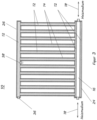
- Fig. 3 shows the radiator 10 according to Fig. 1 in sectional view, wherein a cavity formed by the heat pipes 14 and the cross-connecting pipes 24, 26 is filled with the working medium 12, shown in grey.
- Fig. 4 shows a side view of the radiator 10 , wherein the heating medium 18 flowing in the heating pipe 16, such as water, is shown in grey.
- Fig. 5 shows the radiator 10, partly in section and partly with cladding elements 42 and radiation plates 40, which are thermally coupled to the heat pipes 14 or cross-connection pipes 24, 26.
- Fig. 6 shows a perspective view of the heat pipe 14 with the flat heat radiation element 40, which is thermally coupled to the heat pipe 14 via connecting plates 44 as convection elements.
- the heat radiation elements 40, 44 lie in one plane in the assembled state and are preferably on both a front and a back of the radiator.
- Fig. 7 shows a second embodiment of a radiator 46, preferably made of steel, with a connection system 48 that can be adapted to various radiator connections.
- the connection system 48 comprises a flow connection 50, which is connected via a bypass pipe 52 to an inlet of a preferably commercially available control valve 54, which is coupled to a docking pipe end 56 extending from the second cross-connection pipe 26.
- a second bypass pipe 58 runs from the control valve 54 in the direction of the heating pipe 16 and is in fluid communication with it.
- a heating medium flow divider 60 is arranged coaxially inside the heating pipe 16, via which heating medium is guided from the second bypass pipe 58 through the heating pipe 16 and back to a return connection 62.
- the heating medium flow divider 60 starts from an orifice 64 which is arranged in a front cross-sectional area of the heating pipe 16 in order to operate the heating element either via the connection pieces 32, 34 of the heating pipe 16 or via the flow and return connections 50, 62.
- Fig. 8 shows a third embodiment of a radiator 66, preferably made of aluminum. This embodiment differs from the embodiment according to Fig. 7 in that the first cross-connection pipe 24 and the heating pipe 16 run parallel to one another and are thermally coupled. Preferably, the first cross-connection pipe 24 and the heating pipe 16 are designed as an extruded profile 68, preferably an extruded aluminum profile.
- the radiator 66 also includes a universal connection system 70 with an inlet 72 which is connected via a first bypass pipe 74 to a commercially available radiator control valve 76, which is coupled to a docking pipe end 78 of the second cross-connection pipe 26.
- a second bypass pipe 80 runs from the control valve 76 in the direction of the heating pipe 16 and is in fluid communication with it.
- a heating medium flow divider 82 runs coaxially inside the heating pipe 16 and is connected to an aperture 84 which is arranged in an opening on the front side of the heating pipe 16. The heating medium is guided via the second bypass pipe 80 along the heating medium flow divider 82 in the longitudinal direction of the heating pipe and back to a return connection 86.
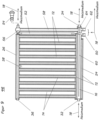
- Fig. 9 shows the radiator 46 in steel design with filled working fluid and Fig. 10 shows the radiator 66 in aluminum design with filled working fluid, each shown in gray.
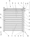
- Fig. 11 and 12 show the radiators 46 and 66 with filled heating medium, each shown in grey.
- Fig. 13 shows an embodiment of a radiator 66 according to Fig. 8 .
- This embodiment differs from the embodiment according to Fig. 8 in that the connection system 70 is thermally coupled to an inlet 86 via a first bypass pipe 74 with the second bypass pipe 80 and with the return connection 72.
- the connection system also works if the connection 72 is the flow and the connection 86 is the return.
- the radiator is only suitable for a "riding connection” or "bottom connection", regardless of the flow direction (flow/return) of the heating medium 18.
- the Fig. 14a and 14b show by way of example various embodiments of the radiators 46, 66 with flat heat-radiating surface elements 88, 92, which are arranged along the heat pipes 14, the bypass pipe 58 according to Fig. 7 and the bypass pipe 80 according to Fig. 8 and Fig. 13
- the surface elements 90, 94 are exemplary claddings.
- Fig. 15 shows in perspective view the heat pipe 14 according to Fig. 14a , b with the flat heat radiation element 88, 92, which is thermally coupled to the heat pipe 14 in the longitudinal direction via connecting plates as convection elements 96.
- the heat radiation elements 88, 92 and convection elements 96 lie in one plane in the assembled state and are preferably connected by joining technology on both a front and a back of the radiator.
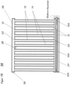
- Fig. 16 shows a fourth embodiment of a radiator 98 in sectional view, which has essentially the same structure as the radiator according to Fig. 1 wherein like elements are provided with like reference numerals.
- the first cross-connecting pipe 24 has, as in Fig. 1 shown, along the central axis a coaxial tube 100 which, in the embodiment shown, accommodates an electric heating rod 102 in the longitudinal direction.
- a heat conducting means 104 is preferably arranged between the heating rod 102 and the tube 100.
- the tube 100 is connected fluid-tight to the cross-connecting tube 24 on the end face and the working medium 12 flows around it on the outside.
- the heating element connection is not limited to the side shown in the picture, it can also be made at the opposite end of the pipe, with the necessary fluid seals as described above.
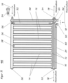
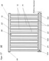
- Fig. 17 shows the radiator 98 with filled working medium 12, shown in grey.
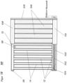
- Fig. 18 shows the radiator 98, partly in section and partly with a covering in the form of flat heat radiation elements 106; which in the longitudinal direction the heat pipes 14.
- the surface elements 108, 109, 110 are exemplary claddings.
- Fig. 19 shows a fifth embodiment of a radiator 112, which has essentially the same structure as the radiator 10 according to Fig. 1 , but the heat pipes 14 are thermally coupled via transverse slats 114. Furthermore, a fan 116 is provided, via which an air flow 118 can be guided through the openings formed between the slats 114.
- Fig. 20 shows the radiator 112 according to Fig. 19 with filled working medium 12, shown in grey.
- Fig. 21 shows the radiator 112 according to Fig. 19 with filled heating medium, such as water 18, shown in grey.
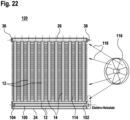
- Fig. 22 shows a sixth embodiment of a radiator 120, which has essentially the same structure as the radiator 98 according to Fig. 16 , but the heat pipes 14 are thermally coupled via transverse slats 114. Furthermore, a fan 116 is provided, via which an air flow 118 can be guided through the openings formed between the slats 114.
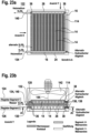
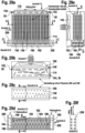
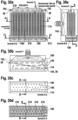
- Fig. 23a to 23c show different views of a heating register 122, consisting of two parallel-connected radiators 112_according to Fig. 19 .
- the heating register 122 comprises a first radiator segment 124 and a second radiator segment 126, wherein the heating pipes 16 are connected in parallel.
- connection pieces 128, 130 are connected together to a flow connection piece 134 via a connecting element 132.
- output connections 136, 138 are connected to a connection piece 140 via a pipe connection.
- the connection system also works if connection 140 is the flow and connection 134 is the return.
- the heating register segments 124, 126 essentially have a structure that corresponds to the structure of the radiator 112 as it is arranged in relation to the Fig. 19 to 21 was described.
- a fan 142 is provided, the longitudinal axis 144 of which runs essentially at right angles to a plane spanned by the segments, so that an air flow can be generated through the opening between the slats 114.
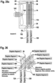
- Fig. 24 shows a purely schematic flow principle of the heating register 122 in a simplified representation.
- the heat pipes 14 of the heating register segments 124, 126 are each in fluid connection with the cross-connection pipes 24, 26.
- the heating pipes 16 run coaxially to the cross-connection pipes 24, which in the embodiment shown carry water as the heating medium. These are connected in parallel on the inlet and outlet sides in order to create a hydraulic balance. Alternatively, additional hydraulic balancing valves can be provided as shown. It is also possible to connect additional segments in parallel, as shown by another cross-connection pipe.
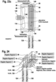
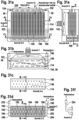
- Fig. 25a to 25c shows an embodiment of a radiator 122, according to Fig. 23 each in different views, with electric heating rods 102 being provided as the heating medium.
- the heating register comprises a first heating element segment 124 and a second heating element segment 126.
- the heating register segments 124, 126 essentially have a structure similar to that of the radiator 120 Fig. 22 corresponds to how it relates to the Fig. 19 to 22 was described.
- the heating element connections are not limited to the side shown in the picture, they can also be made on the opposite pipe ends, with the necessary fluid seals as described above.
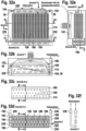
- Fig. 26 shows a purely schematic flow principle of the heating register 122 in a simplified representation.
- the heat pipes 14 of the heating register segments 124, 126 are each in fluid connection with the cross-connection pipes 24, 26.
- Pipes 100 run coaxially to the cross-connection pipes 24, which in the embodiment shown accommodate the electric heating rods 102. It is also possible to connect further segments in parallel, as shown by another cross-connection pipe.
- Fig. 27 shows a front view of a seventh embodiment of a heating element 146 in the form of a meander-shaped heat pipe bundle 148, which is filled with a working medium 150 and is sealed fluid-tight at its ends 152, 154.
- Parallel pipe sections 156 of the pipe bundle 148 form heat pipes, while first curved pipe sections 158 form an evaporator 160 and second curved pipe sections 156 form a condenser 162.
- the pipe sections 158 which act as evaporators, are thermally coupled to a heat source 164 such as a heating pipe.
- a heat source 164 such as a heating pipe.
- the heating pipe 164 runs in a heat-conducting body 166, which is made of a heat transfer medium such as aluminum or copper or advantageously a heat-conductive material.
- the heating medium 18 such as water flows through the heating pipe 164 in order to transfer heat to the pipe sections 158.
- a safety valve 38 is preferably arranged at the end of the pipe section 152 and a filling valve 36 at the end of the pipe bundle 154. In terms of construction, any other advantageous position of the safety valve 38 and filling valve 36 or the hollow spaces filled with the working fluid is also possible. If technical guidelines require it, an advantageous safety encapsulation of the valve 38 is provided.
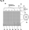
- Fig. 28 shows another embodiment of a radiator 168, according to Fig.27 wherein the heat source is designed as an electric heating rod 170 with connection 172.
- the electric heating rod 170 extends in an opening 174 in the heat conducting body 166.
- a heat conducting means 176 is provided at the transition between the electric heating rod 170 and the heat conducting body 166.
- Fig. 32 a) to f) show views of an embodiment of a radiator 226 which is substantially similar to the radiator 178 according to Fig. 29 a) to e) , with the difference that the ends 190, 192, 194, 196; 198, 200, 202, 204 of the heating tubes 182, 184, 186, 188 do not end in the common flange 206, 208 but are connected in series by means of connecting connections 228, 230.
Landscapes
- Engineering & Computer Science (AREA)
- General Engineering & Computer Science (AREA)
- Mechanical Engineering (AREA)
- Thermal Sciences (AREA)
- Physics & Mathematics (AREA)
- Combustion & Propulsion (AREA)
- Life Sciences & Earth Sciences (AREA)
- Chemical & Material Sciences (AREA)
- Sustainable Development (AREA)
- Domestic Hot-Water Supply Systems And Details Of Heating Systems (AREA)
- Instantaneous Water Boilers, Portable Hot-Water Supply Apparatuses, And Control Of Portable Hot-Water Supply Apparatuses (AREA)
- Central Heating Systems (AREA)
- Heat-Exchange Devices With Radiators And Conduit Assemblies (AREA)
- Details Of Fluid Heaters (AREA)
- Resistance Heating (AREA)
Priority Applications (1)
| Application Number | Priority Date | Filing Date | Title |
|---|---|---|---|
| EP24213291.8A EP4498027A3 (de) | 2019-12-10 | 2019-12-13 | Heizkörper |
Applications Claiming Priority (2)
| Application Number | Priority Date | Filing Date | Title |
|---|---|---|---|
| DE102019133802 | 2019-12-10 | ||
| PCT/EP2019/085116 WO2021115617A1 (de) | 2019-12-10 | 2019-12-13 | Heizkörper |
Related Child Applications (2)
| Application Number | Title | Priority Date | Filing Date |
|---|---|---|---|
| EP24213291.8A Division-Into EP4498027A3 (de) | 2019-12-10 | 2019-12-13 | Heizkörper |
| EP24213291.8A Division EP4498027A3 (de) | 2019-12-10 | 2019-12-13 | Heizkörper |
Publications (3)
| Publication Number | Publication Date |
|---|---|
| EP4073447A1 EP4073447A1 (de) | 2022-10-19 |
| EP4073447C0 EP4073447C0 (de) | 2025-01-22 |
| EP4073447B1 true EP4073447B1 (de) | 2025-01-22 |
Family
ID=69147596
Family Applications (2)
| Application Number | Title | Priority Date | Filing Date |
|---|---|---|---|
| EP19832863.5A Active EP4073447B1 (de) | 2019-12-10 | 2019-12-13 | Heizkörper |
| EP24213291.8A Pending EP4498027A3 (de) | 2019-12-10 | 2019-12-13 | Heizkörper |
Family Applications After (1)
| Application Number | Title | Priority Date | Filing Date |
|---|---|---|---|
| EP24213291.8A Pending EP4498027A3 (de) | 2019-12-10 | 2019-12-13 | Heizkörper |
Country Status (8)
| Country | Link |
|---|---|
| US (1) | US12529523B2 (pl) |
| EP (2) | EP4073447B1 (pl) |
| JP (2) | JP7485765B2 (pl) |
| KR (1) | KR102879172B1 (pl) |
| CN (1) | CN114829861B (pl) |
| CA (1) | CA3163868A1 (pl) |
| PL (1) | PL4073447T3 (pl) |
| WO (1) | WO2021115617A1 (pl) |
Families Citing this family (3)
| Publication number | Priority date | Publication date | Assignee | Title |
|---|---|---|---|---|
| NO20221151A1 (en) * | 2022-10-27 | 2024-04-29 | Al Janabi Ziad | Heating Radiator HRZTECH |
| KR102935379B1 (ko) * | 2023-07-12 | 2026-03-09 | 농업회사법인 주식회사 쏠바이오 | 열전달 효율이 향상된 일체형 방열관 |
| DE102024132934A1 (de) * | 2024-11-12 | 2026-05-13 | Ista Se | Heizkostenverteiler, System und Verfahren zum Betrieb eines Heizkostenverteilers |
Family Cites Families (62)
| Publication number | Priority date | Publication date | Assignee | Title |
|---|---|---|---|---|
| NO781671L (no) * | 1977-05-16 | 1978-11-17 | Bulten Kanthal Ab | Radiator. |
| GB2099980B (en) * | 1981-05-06 | 1985-04-24 | Scurrah Norman Hugh | Heat transfer panels |
| JPS5860135A (ja) * | 1981-10-01 | 1983-04-09 | Tokyo Electric Power Co Inc:The | 繊維強化プラスチックス成形品の成形方法 |
| US4567351A (en) * | 1983-08-10 | 1986-01-28 | Matsushita Electric Works, Ltd. | Electric space heater employing a vaporizable heat exchange fluid |
| JPS61149010U (pl) | 1985-03-01 | 1986-09-13 | ||
| JPS6346344A (ja) | 1986-08-12 | 1988-02-27 | Fuji Electric Co Ltd | ヒ−トパイプ式集熱兼放熱装置 |
| DE3731160A1 (de) | 1987-09-17 | 1989-03-30 | Bernhard Kessel | Verwendung eines reinigungsrohres fuer durchgehende abwasser-rohrleitungen als rueckflussverhinderer fuer jegliche abwaesserarten |
| JPH063302Y2 (ja) | 1987-11-06 | 1994-01-26 | シャープ株式会社 | ヒートパイプ式床暖房パネル |
| FR2654808A1 (fr) * | 1989-11-20 | 1991-05-24 | Teytu Andre | Radiateur a resistance electrique. |
| JPH04203891A (ja) * | 1990-11-30 | 1992-07-24 | Nippondenso Co Ltd | 冷暖房兼用熱交換器 |
| JP3364764B2 (ja) | 1993-09-13 | 2003-01-08 | アクトロニクス株式会社 | 密閉機器筐体冷却装置 |
| JPH08152283A (ja) | 1994-11-30 | 1996-06-11 | Mitsubishi Cable Ind Ltd | 分割型ヒートパイプの製造方法 |
| US5921315A (en) * | 1995-06-07 | 1999-07-13 | Heat Pipe Technology, Inc. | Three-dimensional heat pipe |
| GB9516125D0 (en) * | 1995-08-07 | 1995-10-04 | Ici Plc | Heat exchange apparatus and process |
| JPH10274488A (ja) * | 1997-03-31 | 1998-10-13 | Showa Alum Corp | ヒートパイプ式熱交換器 |
| JPH11351769A (ja) | 1998-06-12 | 1999-12-24 | Furukawa Electric Co Ltd:The | ヒートシンク |
| AU2001277627A1 (en) | 2000-08-11 | 2002-02-25 | Lambco Holdings Ltd | An improved heater |
| WO2002050479A1 (en) * | 2000-12-19 | 2002-06-27 | Lambco Holdings Limited | An improved heater |
| JP3797910B2 (ja) | 2001-10-18 | 2006-07-19 | 大阪瓦斯株式会社 | 暖房装置 |
| JP2003276427A (ja) * | 2002-03-25 | 2003-09-30 | Denso Corp | 空調装置の凝縮器まわりの配管付属品 |
| AU2003224357B8 (en) * | 2002-05-10 | 2009-06-18 | George Sandor Viczena | Control of air conditioning cooling or heating coil |
| DE10350192A1 (de) * | 2002-10-30 | 2004-05-19 | Denso Corp., Kariya | Kühlkreissystem |
| JP4114471B2 (ja) * | 2002-12-06 | 2008-07-09 | 株式会社デンソー | 冷凍サイクル装置 |
| JP2004322914A (ja) * | 2003-04-25 | 2004-11-18 | Denso Corp | 複合サイクル用熱交換器 |
| JP2004332975A (ja) | 2003-05-01 | 2004-11-25 | Wel Research Co Ltd | ヒートパイプおよびその作製方法 |
| CZ13445U1 (cs) * | 2003-05-14 | 2003-06-30 | Korado A. S. | Otopné deskové těleso pro kombinované vytápění |
| JP2004353874A (ja) * | 2003-05-26 | 2004-12-16 | Hitoshi Shiga | 熱交換器及びそれを備えた家屋の冷暖房構造並びにその施工方法 |
| ES2557473T3 (es) * | 2004-12-13 | 2016-01-26 | Guoning Yao | Radiador eléctrico mejorado cargado con aceite |
| CN100428450C (zh) | 2005-07-18 | 2008-10-22 | 富准精密工业(深圳)有限公司 | 热管散热装置 |
| KR100771095B1 (ko) * | 2005-09-01 | 2007-10-30 | 이광표 | 열풍기 |
| CN2879091Y (zh) * | 2006-02-20 | 2007-03-14 | 贾风允 | 热管散热器 |
| JP4682932B2 (ja) * | 2006-06-26 | 2011-05-11 | 株式会社デンソー | ループ式ヒートパイプ |
| US8180205B2 (en) | 2007-01-12 | 2012-05-15 | Guoning Yao | Electrothermal oil radiator |
| JP2009008318A (ja) * | 2007-06-27 | 2009-01-15 | Denso Corp | 排熱回収装置 |
| DE202007015734U1 (de) | 2007-11-06 | 2008-03-13 | Kass, Michael | Mehrteiliger Heizkörper |
| JP4803199B2 (ja) * | 2008-03-27 | 2011-10-26 | 株式会社デンソー | 冷凍サイクル装置 |
| JP2009257708A (ja) * | 2008-04-21 | 2009-11-05 | Daikin Ind Ltd | 熱交換器ユニット |
| CN201309432Y (zh) | 2008-07-25 | 2009-09-16 | 中国北车股份有限公司大连电力牵引研发中心 | 电气化铁路接触网配套单/三相电源变换装置 |
| KR200456010Y1 (ko) * | 2008-09-23 | 2011-10-07 | 정방균 | 전기 방열기 |
| US8431873B2 (en) * | 2008-09-29 | 2013-04-30 | Chaun-Choung Technology Corp. | Vane type electric heater and vane structure thereof |
| CN101533810A (zh) * | 2009-04-20 | 2009-09-16 | 浙江大学 | 带泡沫的脉动热管散热器 |
| CN101603790B (zh) * | 2009-07-06 | 2011-11-30 | 张志宇 | 多相变单元组合换热器及其最低壁温控制方法 |
| JP5732258B2 (ja) * | 2010-02-16 | 2015-06-10 | 株式会社ケーヒン・サーマル・テクノロジー | コンデンサ |
| US9664087B2 (en) * | 2010-07-22 | 2017-05-30 | Wescast Industries, Inc. | Exhaust heat recovery system with bypass |
| JP5655676B2 (ja) * | 2010-08-03 | 2015-01-21 | 株式会社デンソー | 凝縮器 |
| JP5799792B2 (ja) * | 2011-01-07 | 2015-10-28 | 株式会社デンソー | 冷媒放熱器 |
| JP5421933B2 (ja) * | 2011-01-12 | 2014-02-19 | サンデン株式会社 | 熱交換器 |
| JP2012202609A (ja) * | 2011-03-25 | 2012-10-22 | Daikin Industries Ltd | 水熱交換器 |
| US10962307B2 (en) * | 2013-02-27 | 2021-03-30 | Denso Corporation | Stacked heat exchanger |
| KR20150028468A (ko) * | 2013-09-06 | 2015-03-16 | 주식회사 올진산업 | 전기 순간온수기용 가열장치 |
| US10234181B2 (en) * | 2013-11-18 | 2019-03-19 | Carrier Corporation | Flash gas bypass evaporator |
| JP2015108489A (ja) * | 2013-12-05 | 2015-06-11 | 新晃工業株式会社 | 空調機の熱交換器 |
| JP6222042B2 (ja) * | 2014-05-23 | 2017-11-01 | 株式会社デンソー | 積層型熱交換器 |
| CN104048548B (zh) * | 2014-05-26 | 2016-01-27 | 杭州三花微通道换热器有限公司 | 可调节的制冷剂分配装置和具有它的换热器 |
| US10240837B2 (en) * | 2014-07-30 | 2019-03-26 | Mitsubishi Electric Corporation | Outdoor unit and refrigeration cycle apparatus |
| CN204202453U (zh) | 2014-08-22 | 2015-03-11 | 嗦魔乐科技有限公司 | 热管式散热器 |
| EP3209957B1 (en) | 2014-10-21 | 2021-04-07 | LG Electronics Inc. | Defrosting device and refrigerator having the same |
| CN105651090B (zh) * | 2016-02-20 | 2017-09-01 | 内蒙古博特科技有限责任公司 | 新型三维螺旋冷凝结构纳米脉动热超导装置 |
| CN205825783U (zh) * | 2016-06-20 | 2016-12-21 | 山东沃亚森曼机械科技有限公司 | 一种双分水片形散热管及采暖散热器 |
| US11193701B2 (en) * | 2017-06-09 | 2021-12-07 | Mitsubishi Electric Corporation | Heat exchanger and refrigeration cycle apparatus |
| JP7073863B2 (ja) * | 2018-04-06 | 2022-05-24 | 株式会社デンソー | 車両用熱管理システム |
| JP2025046344A (ja) | 2023-09-21 | 2025-04-02 | ソフトバンクグループ株式会社 | システム |
-
2019
- 2019-12-13 CN CN201980102893.1A patent/CN114829861B/zh active Active
- 2019-12-13 CA CA3163868A patent/CA3163868A1/en active Pending
- 2019-12-13 JP JP2022536506A patent/JP7485765B2/ja active Active
- 2019-12-13 PL PL19832863.5T patent/PL4073447T3/pl unknown
- 2019-12-13 KR KR1020227022637A patent/KR102879172B1/ko active Active
- 2019-12-13 US US17/777,825 patent/US12529523B2/en active Active
- 2019-12-13 EP EP19832863.5A patent/EP4073447B1/de active Active
- 2019-12-13 EP EP24213291.8A patent/EP4498027A3/de active Pending
- 2019-12-13 WO PCT/EP2019/085116 patent/WO2021115617A1/de not_active Ceased
-
2024
- 2024-05-02 JP JP2024074853A patent/JP2024109632A/ja active Pending
Also Published As
| Publication number | Publication date |
|---|---|
| KR102879172B1 (ko) | 2025-11-03 |
| CN114829861B (zh) | 2026-06-12 |
| EP4073447C0 (de) | 2025-01-22 |
| JP2024109632A (ja) | 2024-08-14 |
| EP4073447A1 (de) | 2022-10-19 |
| CA3163868A1 (en) | 2021-06-17 |
| CN114829861A (zh) | 2022-07-29 |
| US12529523B2 (en) | 2026-01-20 |
| EP4498027A3 (de) | 2025-04-23 |
| JP7485765B2 (ja) | 2024-05-16 |
| JP2023506237A (ja) | 2023-02-15 |
| US20220412665A1 (en) | 2022-12-29 |
| EP4498027A2 (de) | 2025-01-29 |
| KR20220107279A (ko) | 2022-08-02 |
| PL4073447T3 (pl) | 2025-05-19 |
| WO2021115617A1 (de) | 2021-06-17 |
Similar Documents
| Publication | Publication Date | Title |
|---|---|---|
| DE2602530B1 (de) | Latentwaermespeicher | |
| EP4498027A2 (de) | Heizkörper | |
| DE102012112505B3 (de) | Schaltschrank mit einer Anordnung zur Kühlung von in einem Innenraum des Schaltschranks aufgenommenen, Wärme abgebenden Komponenten | |
| WO2012079609A1 (de) | Wärmetauscherpaneel als zwei-phasen-thermosyphon | |
| DE202006007585U1 (de) | Kühl- und/oder Gefriergerät | |
| WO2016066489A1 (de) | Kältegerät mit einem wärmetauschelement | |
| AT519899B1 (de) | Kühldeckenelement | |
| DE202015005746U1 (de) | Solarkollektor und Solarklimaanlage, die diesen umfasst | |
| DE102015207844A1 (de) | Kältegerät mit einem Wärmetauscher | |
| DE1579777C (pl) | ||
| US20260118066A1 (en) | Heating body | |
| DE102011052722B3 (de) | Anordnung eines Kühlkörpers sowie eines elektronischen Bauteils | |
| WO2010028819A2 (de) | Solarkollektor, welcher ein wärmerohr mit kondensator aufweist | |
| EP1674801B1 (de) | Klimaelement | |
| DE202010009468U1 (de) | Speicher mit Direktkondensation | |
| DE1579777B2 (de) | Raumheizungsanlage mit waermespeicherofen | |
| HK40079275B (zh) | 加热体 | |
| CH658299A5 (de) | Ventilatorvorrichtung mit zwei gegensinnig laufenden ventilatoren. | |
| HK40079275A (zh) | 加热体 | |
| EP3598009B1 (de) | Wasserverteilung | |
| DE102023207543A1 (de) | Wärmepumpe | |
| DE102010035567B4 (de) | Lufttechnische Einrichtung zur Klimatisierung eines Raumes | |
| EP0212739A1 (de) | Luft-Luft-Wärmeaustauscher mit Wärmerohren | |
| WO2016087210A1 (de) | Kältegerät mit einem wärmekreislauf | |
| DE963180C (de) | Heiz- oder Kuehlanlage fuer Wohngebaeude |
Legal Events
| Date | Code | Title | Description |
|---|---|---|---|
| STAA | Information on the status of an ep patent application or granted ep patent |
Free format text: STATUS: UNKNOWN |
|
| STAA | Information on the status of an ep patent application or granted ep patent |
Free format text: STATUS: THE INTERNATIONAL PUBLICATION HAS BEEN MADE |
|
| PUAI | Public reference made under article 153(3) epc to a published international application that has entered the european phase |
Free format text: ORIGINAL CODE: 0009012 |
|
| STAA | Information on the status of an ep patent application or granted ep patent |
Free format text: STATUS: REQUEST FOR EXAMINATION WAS MADE |
|
| 17P | Request for examination filed |
Effective date: 20220624 |
|
| AK | Designated contracting states |
Kind code of ref document: A1 Designated state(s): AL AT BE BG CH CY CZ DE DK EE ES FI FR GB GR HR HU IE IS IT LI LT LU LV MC MK MT NL NO PL PT RO RS SE SI SK SM TR |
|
| DAV | Request for validation of the european patent (deleted) | ||
| DAX | Request for extension of the european patent (deleted) | ||
| REG | Reference to a national code |
Ref country code: HK Ref legal event code: DE Ref document number: 40079275 Country of ref document: HK |
|
| P01 | Opt-out of the competence of the unified patent court (upc) registered |
Effective date: 20230530 |
|
| GRAP | Despatch of communication of intention to grant a patent |
Free format text: ORIGINAL CODE: EPIDOSNIGR1 |
|
| STAA | Information on the status of an ep patent application or granted ep patent |
Free format text: STATUS: GRANT OF PATENT IS INTENDED |
|
| INTG | Intention to grant announced |
Effective date: 20240103 |
|
| GRAJ | Information related to disapproval of communication of intention to grant by the applicant or resumption of examination proceedings by the epo deleted |
Free format text: ORIGINAL CODE: EPIDOSDIGR1 |
|
| STAA | Information on the status of an ep patent application or granted ep patent |
Free format text: STATUS: REQUEST FOR EXAMINATION WAS MADE |
|
| INTC | Intention to grant announced (deleted) | ||
| GRAP | Despatch of communication of intention to grant a patent |
Free format text: ORIGINAL CODE: EPIDOSNIGR1 |
|
| STAA | Information on the status of an ep patent application or granted ep patent |
Free format text: STATUS: GRANT OF PATENT IS INTENDED |
|
| INTG | Intention to grant announced |
Effective date: 20240712 |
|
| GRAS | Grant fee paid |
Free format text: ORIGINAL CODE: EPIDOSNIGR3 |
|
| GRAA | (expected) grant |
Free format text: ORIGINAL CODE: 0009210 |
|
| STAA | Information on the status of an ep patent application or granted ep patent |
Free format text: STATUS: THE PATENT HAS BEEN GRANTED |
|
| AK | Designated contracting states |
Kind code of ref document: B1 Designated state(s): AL AT BE BG CH CY CZ DE DK EE ES FI FR GB GR HR HU IE IS IT LI LT LU LV MC MK MT NL NO PL PT RO RS SE SI SK SM TR |
|
| REG | Reference to a national code |
Ref country code: GB Ref legal event code: FG4D Free format text: NOT ENGLISH |
|
| REG | Reference to a national code |
Ref country code: CH Ref legal event code: EP |
|
| REG | Reference to a national code |
Ref country code: IE Ref legal event code: FG4D Free format text: LANGUAGE OF EP DOCUMENT: GERMAN |
|
| REG | Reference to a national code |
Ref country code: DE Ref legal event code: R096 Ref document number: 502019012868 Country of ref document: DE |
|
| P04 | Withdrawal of opt-out of the competence of the unified patent court (upc) registered |
Free format text: CASE NUMBER: APP_6910/2025 Effective date: 20250210 |
|
| U01 | Request for unitary effect filed |
Effective date: 20250207 |
|
| U07 | Unitary effect registered |
Designated state(s): AT BE BG DE DK EE FI FR IT LT LU LV MT NL PT RO SE SI Effective date: 20250213 |
|
| PG25 | Lapsed in a contracting state [announced via postgrant information from national office to epo] |
Ref country code: RS Free format text: LAPSE BECAUSE OF FAILURE TO SUBMIT A TRANSLATION OF THE DESCRIPTION OR TO PAY THE FEE WITHIN THE PRESCRIBED TIME-LIMIT Effective date: 20250422 |
|
| PG25 | Lapsed in a contracting state [announced via postgrant information from national office to epo] |
Ref country code: ES Free format text: LAPSE BECAUSE OF FAILURE TO SUBMIT A TRANSLATION OF THE DESCRIPTION OR TO PAY THE FEE WITHIN THE PRESCRIBED TIME-LIMIT Effective date: 20250122 |
|
| PG25 | Lapsed in a contracting state [announced via postgrant information from national office to epo] |
Ref country code: NO Free format text: LAPSE BECAUSE OF FAILURE TO SUBMIT A TRANSLATION OF THE DESCRIPTION OR TO PAY THE FEE WITHIN THE PRESCRIBED TIME-LIMIT Effective date: 20250422 Ref country code: IS Free format text: LAPSE BECAUSE OF FAILURE TO SUBMIT A TRANSLATION OF THE DESCRIPTION OR TO PAY THE FEE WITHIN THE PRESCRIBED TIME-LIMIT Effective date: 20250522 |
|
| PG25 | Lapsed in a contracting state [announced via postgrant information from national office to epo] |
Ref country code: HR Free format text: LAPSE BECAUSE OF FAILURE TO SUBMIT A TRANSLATION OF THE DESCRIPTION OR TO PAY THE FEE WITHIN THE PRESCRIBED TIME-LIMIT Effective date: 20250122 |
|
| PG25 | Lapsed in a contracting state [announced via postgrant information from national office to epo] |
Ref country code: GR Free format text: LAPSE BECAUSE OF FAILURE TO SUBMIT A TRANSLATION OF THE DESCRIPTION OR TO PAY THE FEE WITHIN THE PRESCRIBED TIME-LIMIT Effective date: 20250423 |
|
| PG25 | Lapsed in a contracting state [announced via postgrant information from national office to epo] |
Ref country code: SM Free format text: LAPSE BECAUSE OF FAILURE TO SUBMIT A TRANSLATION OF THE DESCRIPTION OR TO PAY THE FEE WITHIN THE PRESCRIBED TIME-LIMIT Effective date: 20250122 |
|
| PG25 | Lapsed in a contracting state [announced via postgrant information from national office to epo] |
Ref country code: SK Free format text: LAPSE BECAUSE OF FAILURE TO SUBMIT A TRANSLATION OF THE DESCRIPTION OR TO PAY THE FEE WITHIN THE PRESCRIBED TIME-LIMIT Effective date: 20250122 |
|
| PLBE | No opposition filed within time limit |
Free format text: ORIGINAL CODE: 0009261 |
|
| STAA | Information on the status of an ep patent application or granted ep patent |
Free format text: STATUS: NO OPPOSITION FILED WITHIN TIME LIMIT |
|
| REG | Reference to a national code |
Ref country code: CH Ref legal event code: L10 Free format text: ST27 STATUS EVENT CODE: U-0-0-L10-L00 (AS PROVIDED BY THE NATIONAL OFFICE) Effective date: 20251203 |
|
| 26N | No opposition filed |
Effective date: 20251023 |
|
| PGFP | Annual fee paid to national office [announced via postgrant information from national office to epo] |
Ref country code: GB Payment date: 20251114 Year of fee payment: 7 |
|
| PGFP | Annual fee paid to national office [announced via postgrant information from national office to epo] |
Ref country code: TR Payment date: 20251208 Year of fee payment: 7 |
|
| PGFP | Annual fee paid to national office [announced via postgrant information from national office to epo] |
Ref country code: IE Payment date: 20251219 Year of fee payment: 7 Ref country code: CZ Payment date: 20251210 Year of fee payment: 7 |
|
| U20 | Renewal fee for the european patent with unitary effect paid |
Year of fee payment: 7 Effective date: 20251217 |
|
| PGFP | Annual fee paid to national office [announced via postgrant information from national office to epo] |
Ref country code: PL Payment date: 20251120 Year of fee payment: 7 |
|
| PG25 | Lapsed in a contracting state [announced via postgrant information from national office to epo] |
Ref country code: MC Free format text: LAPSE BECAUSE OF FAILURE TO SUBMIT A TRANSLATION OF THE DESCRIPTION OR TO PAY THE FEE WITHIN THE PRESCRIBED TIME-LIMIT Effective date: 20250122 |
|
| REG | Reference to a national code |
Ref country code: CH Ref legal event code: H13 Free format text: ST27 STATUS EVENT CODE: U-0-0-H10-H13 (AS PROVIDED BY THE NATIONAL OFFICE) Effective date: 20260723 |