EP4067663B1 - Verstopfungsfreie pumpe - Google Patents
Verstopfungsfreie pumpe Download PDFInfo
- Publication number
- EP4067663B1 EP4067663B1 EP20894890.1A EP20894890A EP4067663B1 EP 4067663 B1 EP4067663 B1 EP 4067663B1 EP 20894890 A EP20894890 A EP 20894890A EP 4067663 B1 EP4067663 B1 EP 4067663B1
- Authority
- EP
- European Patent Office
- Prior art keywords
- foreign matter
- suction port
- impeller
- rotating shaft
- inner periphery
- Prior art date
- Legal status (The legal status is an assumption and is not a legal conclusion. Google has not performed a legal analysis and makes no representation as to the accuracy of the status listed.)
- Active
Links
Images





Classifications
-
- F—MECHANICAL ENGINEERING; LIGHTING; HEATING; WEAPONS; BLASTING
- F04—POSITIVE - DISPLACEMENT MACHINES FOR LIQUIDS; PUMPS FOR LIQUIDS OR ELASTIC FLUIDS
- F04D—NON-POSITIVE-DISPLACEMENT PUMPS
- F04D7/00—Pumps adapted for handling specific fluids, e.g. by selection of specific materials for pumps or pump parts
- F04D7/02—Pumps adapted for handling specific fluids, e.g. by selection of specific materials for pumps or pump parts of centrifugal type
- F04D7/04—Pumps adapted for handling specific fluids, e.g. by selection of specific materials for pumps or pump parts of centrifugal type the fluids being viscous or non-homogenous
-
- F—MECHANICAL ENGINEERING; LIGHTING; HEATING; WEAPONS; BLASTING
- F04—POSITIVE - DISPLACEMENT MACHINES FOR LIQUIDS; PUMPS FOR LIQUIDS OR ELASTIC FLUIDS
- F04D—NON-POSITIVE-DISPLACEMENT PUMPS
- F04D7/00—Pumps adapted for handling specific fluids, e.g. by selection of specific materials for pumps or pump parts
- F04D7/02—Pumps adapted for handling specific fluids, e.g. by selection of specific materials for pumps or pump parts of centrifugal type
- F04D7/04—Pumps adapted for handling specific fluids, e.g. by selection of specific materials for pumps or pump parts of centrifugal type the fluids being viscous or non-homogenous
- F04D7/045—Pumps adapted for handling specific fluids, e.g. by selection of specific materials for pumps or pump parts of centrifugal type the fluids being viscous or non-homogenous with means for comminuting, mixing stirring or otherwise treating
-
- F—MECHANICAL ENGINEERING; LIGHTING; HEATING; WEAPONS; BLASTING
- F04—POSITIVE - DISPLACEMENT MACHINES FOR LIQUIDS; PUMPS FOR LIQUIDS OR ELASTIC FLUIDS
- F04D—NON-POSITIVE-DISPLACEMENT PUMPS
- F04D13/00—Pumping installations or systems
- F04D13/02—Units comprising pumps and their driving means
- F04D13/06—Units comprising pumps and their driving means the pump being electrically driven
- F04D13/08—Units comprising pumps and their driving means the pump being electrically driven for submerged use
-
- F—MECHANICAL ENGINEERING; LIGHTING; HEATING; WEAPONS; BLASTING
- F04—POSITIVE - DISPLACEMENT MACHINES FOR LIQUIDS; PUMPS FOR LIQUIDS OR ELASTIC FLUIDS
- F04D—NON-POSITIVE-DISPLACEMENT PUMPS
- F04D29/00—Details, component parts, or accessories
- F04D29/18—Rotors
- F04D29/20—Mounting rotors on shafts
-
- F—MECHANICAL ENGINEERING; LIGHTING; HEATING; WEAPONS; BLASTING
- F04—POSITIVE - DISPLACEMENT MACHINES FOR LIQUIDS; PUMPS FOR LIQUIDS OR ELASTIC FLUIDS
- F04D—NON-POSITIVE-DISPLACEMENT PUMPS
- F04D29/00—Details, component parts, or accessories
- F04D29/18—Rotors
- F04D29/22—Rotors specially for centrifugal pumps
-
- F—MECHANICAL ENGINEERING; LIGHTING; HEATING; WEAPONS; BLASTING
- F04—POSITIVE - DISPLACEMENT MACHINES FOR LIQUIDS; PUMPS FOR LIQUIDS OR ELASTIC FLUIDS
- F04D—NON-POSITIVE-DISPLACEMENT PUMPS
- F04D29/00—Details, component parts, or accessories
- F04D29/18—Rotors
- F04D29/22—Rotors specially for centrifugal pumps
- F04D29/2261—Rotors specially for centrifugal pumps with special measures
- F04D29/2288—Rotors specially for centrifugal pumps with special measures for comminuting, mixing or separating
-
- F—MECHANICAL ENGINEERING; LIGHTING; HEATING; WEAPONS; BLASTING
- F04—POSITIVE - DISPLACEMENT MACHINES FOR LIQUIDS; PUMPS FOR LIQUIDS OR ELASTIC FLUIDS
- F04D—NON-POSITIVE-DISPLACEMENT PUMPS
- F04D29/00—Details, component parts, or accessories
- F04D29/18—Rotors
- F04D29/22—Rotors specially for centrifugal pumps
- F04D29/24—Vanes
- F04D29/242—Geometry, shape
-
- F—MECHANICAL ENGINEERING; LIGHTING; HEATING; WEAPONS; BLASTING
- F04—POSITIVE - DISPLACEMENT MACHINES FOR LIQUIDS; PUMPS FOR LIQUIDS OR ELASTIC FLUIDS
- F04D—NON-POSITIVE-DISPLACEMENT PUMPS
- F04D29/00—Details, component parts, or accessories
- F04D29/40—Casings; Connections of working fluid
- F04D29/42—Casings; Connections of working fluid for radial or helico-centrifugal pumps
- F04D29/426—Casings; Connections of working fluid for radial or helico-centrifugal pumps especially adapted for liquid pumps
-
- F—MECHANICAL ENGINEERING; LIGHTING; HEATING; WEAPONS; BLASTING
- F04—POSITIVE - DISPLACEMENT MACHINES FOR LIQUIDS; PUMPS FOR LIQUIDS OR ELASTIC FLUIDS
- F04D—NON-POSITIVE-DISPLACEMENT PUMPS
- F04D29/00—Details, component parts, or accessories
- F04D29/40—Casings; Connections of working fluid
- F04D29/42—Casings; Connections of working fluid for radial or helico-centrifugal pumps
- F04D29/426—Casings; Connections of working fluid for radial or helico-centrifugal pumps especially adapted for liquid pumps
- F04D29/4273—Casings; Connections of working fluid for radial or helico-centrifugal pumps especially adapted for liquid pumps suction eyes
-
- F—MECHANICAL ENGINEERING; LIGHTING; HEATING; WEAPONS; BLASTING
- F04—POSITIVE - DISPLACEMENT MACHINES FOR LIQUIDS; PUMPS FOR LIQUIDS OR ELASTIC FLUIDS
- F04D—NON-POSITIVE-DISPLACEMENT PUMPS
- F04D29/00—Details, component parts, or accessories
- F04D29/40—Casings; Connections of working fluid
- F04D29/42—Casings; Connections of working fluid for radial or helico-centrifugal pumps
- F04D29/44—Fluid-guiding means, e.g. diffusers
- F04D29/445—Fluid-guiding means, e.g. diffusers especially adapted for liquid pumps
-
- F—MECHANICAL ENGINEERING; LIGHTING; HEATING; WEAPONS; BLASTING
- F04—POSITIVE - DISPLACEMENT MACHINES FOR LIQUIDS; PUMPS FOR LIQUIDS OR ELASTIC FLUIDS
- F04D—NON-POSITIVE-DISPLACEMENT PUMPS
- F04D29/00—Details, component parts, or accessories
- F04D29/70—Suction grids; Strainers; Dust separation; Cleaning
- F04D29/708—Suction grids; Strainers; Dust separation; Cleaning specially for liquid pumps
-
- F—MECHANICAL ENGINEERING; LIGHTING; HEATING; WEAPONS; BLASTING
- F05—INDEXING SCHEMES RELATING TO ENGINES OR PUMPS IN VARIOUS SUBCLASSES OF CLASSES F01-F04
- F05D—INDEXING SCHEME FOR ASPECTS RELATING TO NON-POSITIVE-DISPLACEMENT MACHINES OR ENGINES, GAS-TURBINES OR JET-PROPULSION PLANTS
- F05D2210/00—Working fluids
- F05D2210/10—Kind or type
- F05D2210/11—Kind or type liquid, i.e. incompressible
Definitions
- the present invention relates to a non-clogging pump.
- a non-clogging pump provided with an impeller is known.
- Such a non-clogging pump is disclosed in Japanese Unexamined Patent Publication No. 2005-90313 , US2009/169365 A1 , and CN 203 394 823 U .
- US 3 692 422 A discloses a non-clogging pump at least not having the features of the characterizing portion of claim 1. Further prior art is shown in JP S63 10288 U and US 4 402 648 A .
- Japanese Unexamined Patent Publication No. 2005-90313 discloses a vertical type non-clogging pump that includes an impeller and a flow straightener disposed immediately below the impeller and outside a suction port.
- the flow straightener includes a flow straightening plate that guides and pushes fibrous foreign matter having a cloth shape, a strip shape, or the like toward the outer periphery side of the impeller.
- the flow straightening plate is formed so as to spread in a tapered shape and radially from the lower side toward the upper side.
- the flow straightener is configured to pass the foreign matter by guiding and pushing the foreign matter toward the outer periphery side of the impeller by the flow straightening plate.
- the present invention has been made in order to solve the problems as described above, and an object of the present invention is to provide a non-clogging pump in which it is possible to improve the passage performance of foreign matter without complicating a device configuration.
- a non-clogging pump including: a pump casing provided with a suction port; and an impeller that includes a main plate portion and two or more vane portions that are disposed on a suction port side of the main plate portion, is fixed to one end of a rotating shaft, and is disposed inside the pump casing, in which the main plate portion includes a main plate protrusion portion that protrudes in a counter-inflow direction that is a direction opposite to an inflow direction of water from the suction port, which substantially coincides with an axial direction of the rotating shaft, toward an inner periphery side in a radial direction of the rotating shaft, the vane portion includes a first end face that is an end face in the counter-inflow direction, which is located on an outer periphery side in the radial direction, and extends in a direction intersecting the counter-inflow direction, and
- the vane portion is configured to include the first end face that is an end face in the counter-inflow direction, which is located on the outer periphery side in the radial direction of the rotating shaft, and extends in the direction intersecting the counter-inflow direction, and the second end face (a leading edge) that is an end face in the counter-inflow direction, which is connected to the first end face from the inner periphery side in the radial direction of the first end face and located on the inner periphery side in the radial direction, and is inclined with respect to the first end face so as to be located on the counter-inflow direction side toward the inner periphery side in the radial direction.
- the gap between a flow straightener and a pump main body is not clogged with soft foreign matter, and thus it is possible to improve the passage performance of the foreign matter. As a result, it is possible to improve the passage performance of the foreign matter without complicating a device configuration.
- due to providing two or more vane portions it is possible to dispose the two or more vane portions in a well-balanced manner around the rotating shaft, and therefore, compared to a case where only one vane portion is provided, it is possible to reduce vibration associated with the rotation of the impeller. Therefore, it is possible to suppress a decrease in pump efficiency.
- the main plate portion is provided with the main plate protrusion portion that protrudes in the counter-inflow direction toward the inner periphery side in the radial direction of the rotating shaft, and the suction port protrusion portion that protrudes to the center side of suction port is provided on the inner peripheral wall that forms the suction port of the pump casing. Due to the suction port protrusion portion, the center of the swirling flow (the spirally swirling flow that is generated by the rotation of the impeller) that is generated in the vicinity of the suction port can be made to be eccentric when viewed from the axial direction of the rotating shaft, and therefore, the center of the swirling flow can be shifted from the main plate protrusion portion.
- the foreign matter can be sucked in at an angle with respect to the direction of the rotating shaft.
- the opening area of the suction port is reduced due to the suction port protrusion portion, so that it is possible to increase the suction speed of water and the foreign matter. Therefore, it is possible to suppress a decrease in suction flow velocity even in a small water volume range.
- an angle formed by the second end face and the first end face is an obtuse angle.
- the suction port protrusion portion is formed in an angular range of 45 degrees or larger around the rotating shaft when viewed from the axial direction of the rotating shaft.
- the suction port protrusion portion can be provided in a relatively large angular range, and therefore, the center of the swirling flow that is generated in the vicinity of the suction port can be reliably made to be eccentric. As a result, it is possible to effectively restrain the foreign matter from being entangled in the main plate protrusion portion.
- the suction port protrusion portion since it is possible to cause the suction port protrusion portion to protrude from a relatively large angular range, the opening area of the suction port can be reduced due to the suction port protrusion portion, and thus it is possible to further increase the suction speed of water and the foreign matter. Therefore, it is possible to further suppress a decrease in suction flow velocity even in a small water volume range. Further, since the suction port protrusion portion is formed in a relatively wide angular range, it is possible to restrain soft foreign matter from being entangled in and constrained by the suction port protrusion portion.
- an inner periphery-side end portion of the suction port protrusion portion is disposed on an inner periphery side in the radial direction of the rotating shaft with respect to the inner periphery-side end portion of the vane portion that is connected to the main plate protrusion portion, or at a position substantially corresponding to the inner periphery-side end portion of the vane portion in the radial direction.
- the foreign matter can be cut and crushed to a size in which the foreign matter is not caught in the tongue portion, the outer periphery of the vane portion, and a tip clearance.
- the main plate protrusion portion has, at a tip thereof, an inclined surface inclined with respect to a direction orthogonal to the counter-inflow direction, the inclined surface being configured such that when the impeller rotates, the inclined surface rotates and a force that pushes the foreign matter to the top portion of the inclined surface along the inclined surface can be applied to the foreign matter.
- the force acting on the foreign matter in the inflow direction can be made non-uniform, and therefore, in a case where the foreign matter is entangled in the inclined surface, the foreign matter is out of balance and can be removed from the inclined surface.
- the tip of the main plate protrusion portion has a substantially circular shape when viewed from the axial direction of the rotating shaft.
- the top portion of the inclined surface is formed to be round, and therefore, the effect of removing the foreign matter from the inclined surface is enhanced.
- the inclined surface is provided on an entire tip of the main plate protrusion portion.
- an apex on the counter-inflow direction side of the inclined surface is disposed at a substantially intermediate position between the two vane portions that are located in the vicinity of the apex in the rotation direction of the rotating shaft.
- the inner periphery-side end portion in the counter-inflow direction of the suction port protrusion portion is disposed close to a side surface of the main plate protrusion portion when viewed from the axial direction of the rotating shaft.
- the main plate protrusion portion and the suction port protrusion portion can be disposed with a narrow (small) gap, and therefore, the foreign matter can be effectively cut and crushed in the gap between the main plate protrusion portion and the suction port protrusion portion, and the foreign matter can be more effectively removed from the inclined surface of the impeller.
- the inner periphery-side end portion in the counter-inflow direction of the suction port protrusion portion is disposed between an apex on the counter-inflow direction side of the inclined surface and a point that is located on a bottom on an opposite direction side to the counter-inflow direction of the inclined surface, in the axial direction of the rotating shaft.
- the side surface of the formed inclined surface has a non-uniform length in the direction of the rotating shaft, and therefore, the inner periphery-side end portion of the suction port protrusion portion and the side surface of the main plate protrusion portion smoothly repeat "approach” and "separation” with the rotation of the impeller, so that the foreign matter is easily removed from the inclined surface of the impeller. As a result, the passage performance of the foreign matter can be further improved.
- an inner periphery-side portion in the radial direction of the vane portion (of the rotating shaft) is inclined to be located so as to spread to the outer periphery side in the radial direction toward the counter-inflow direction.
- the vane portion is formed in a so-called screw shape. Therefore, a force that pushes the foreign matter into the impeller can act on the foreign matter with the rotation of the impeller, and therefore, the foreign matter is easily removed from the gap between the suction port protrusion portion and the vane portion. As a result, the passage performance of the foreign matter can be further improved.
- the pump casing has a foreign matter discharge groove that has an elongated shape, is provided on a facing surface on the counter-inflow direction side of the impeller, which faces the impeller, and extends from the inner periphery side toward the outer periphery side in the radial direction of the rotating shaft, and an end portion on the inner periphery side in the radial direction of the foreign matter discharge groove extends to the suction port protrusion portion.
- the pump casing includes the facing surface that surrounds the suction port, faces the impeller from the suction port side, and extends in a direction substantially orthogonal to the axial direction of the rotating shaft, the foreign matter discharge groove is provided on the facing surface, and the foreign matter discharge groove is provided with an edge portion, which changes an angle at which the foreign matter discharge groove extends, in the vicinity of a boundary portion between the suction port protrusion portion and the facing surface when viewed from the axial direction of the rotating shaft.
- an end portion on the outer periphery side in the radial direction of the foreign matter discharge groove is located on the outer periphery side with respect to the vane portion in the radial direction.
- the foreign matter discharge groove is configured to become deeper toward a downstream side from an upstream side in the rotation direction of the impeller along the rotation direction of the impeller.
- the foreign matter discharge groove is configured to widen in width toward an outer periphery from a center of the pump casing. With this configuration, the foreign matter discharge groove is gradually widened in the discharge direction, and therefore, the effect of pushing out the foreign matter in the discharge direction can be obtained.
- an upstream-side side surface of the suction port protrusion portion is disposed in an angular range between a tongue portion of the pump casing and an angular position on an upstream side by 120 degrees with respect to the tongue portion.
- the impeller is configured such that a flow path on a negative pressure surface side of the vane portion is narrower than a flow path on a pressure surface side of the vane portion on the main plate portion side and the inner periphery side in the radial direction.
- the main plate portion is provided with a weight portion having an annular shape and applying an inertial force to the impeller.
- the flywheel effect is an effect of making the rotation speed of a rotating body rotating around a predetermined axis as uniform as possible (an effect of eliminating unevenness of the rotation speed of the rotating body).
- a thickness on the outer periphery side in the radial direction of the vane portion is larger than a thickness on the inner periphery side in the radial direction of the vane portion.
- the non-clogging pump further includes an electric motor that rotates the rotating shaft, in which the non-clogging pump is configured such that a rotational frequency of the electric motor is changeable, and is configured such that in a case where a drive power value of the electric motor falls below a predetermined first threshold value, the rotational frequency of the electric motor is increased until the drive power value of the electric motor reaches the predetermined first threshold value or a predetermined second threshold value exceeding the predetermined first threshold value.
- the non-clogging pump further includes an electric motor that rotates the rotating shaft, in which the non-clogging pump is configured such that in a case where a state where a drive power value of the electric motor exceeds a drive power reference value is continued for a predetermined time or longer, the impeller is rotated in a reverse direction when it is repeatedly determined that the state where the drive power value of the electric motor exceeds the drive power reference value is continued for a predetermined time or longer, even if restart is attempted with the electric motor stopped by a predetermined number of times.
- the non-clogging pump can effectively remove the foreign matter entangled in the impeller, the foreign matter constrained in the pump chamber, or the like.
- the inner peripheral wall that forms the suction port of the pump casing further includes, in addition to the suction port protrusion portion, a recessed portion that is provided on a side opposite to a side where the suction port protrusion portion is disposed with respect to the rotating shaft when viewed in a plan view, and is recessed to an outer periphery side in the radial direction of the suction port.
- the passage performance of the foreign matter can be further improved. Further, due to the recessed portion, even if large foreign matter flows in, the foreign matter is moved to the recessed portion, and the foreign matter can be crushed to a size that allows passage, by "cutting action and crushing action" due to a change in the relative position between the downstream-side side wall in the rotation direction of the recessed portion (the rotation direction of the impeller) and the pressure surface-side edge of the leading edge (the second end face) of the rotating vane portion.
- the non-clogging pump 100 is a vertical type submersible electric pump in which a rotating shaft 1 extends in an up-down direction (a Z direction).
- the non-clogging pump 100 includes the rotating shaft 1, an electric motor 2, a pump casing 3, and an impeller 6.
- the non-clogging pump 100 of the present embodiment is configured to allow even relatively long and wide soft foreign matter (contaminant) (soft foreign matter) or the like, such as a towel, stockings, rubber gloves, bandages, or diapers, to pass (be sucked from a suction port 30 of the pump casing 3 and discharged from a discharge port 31 of the pump casing 3) without clogging.
- contaminant soft foreign matter
- soft foreign matter such as a towel, stockings, rubber gloves, bandages, or diapers
- the non-clogging pump 100 is usually used such that the flow velocity in a discharge pipe (not shown) that is disposed on the downstream side of the discharge port 31 is equal to or higher than the flow velocity (for example, 0.6 m/s) at which it is difficult for a sediment to accumulate in the discharge pipe, and is equal or lower than the flow velocity (for example, 3.0 m/s) at which a pipe wall or painting in the discharge pipe is not damaged.
- the non-clogging pump 100 is used such that the flow velocity in the discharge pipe is about 1.8 m/s.
- the rotating shaft 1 has a columnar shape extending in the up-down direction.
- the impeller 6 is fixed to one end 1a (a lower end) of the rotating shaft 1, and the electric motor 2 (a rotor 21) is fixed to the other end 1b (upper end) side.
- an axial direction of the rotating shaft 1 is indicated by the Z direction.
- the direction (upward direction) from one end 1a toward the other end 1b is indicated by a Z1 direction
- the direction (upward direction) from the other end 1b toward one end 1a is indicated by a Z2 direction.
- An inflow direction in the suction port 30 of the pump casing 3 is a direction that (substantially) coincides with the axial direction of the rotating shaft 1 (the Z1 direction from one end 1a toward the other end 1b). Further, a counter-inflow direction, which is the direction opposite to the inflow direction in the suction port 30 of the pump casing 3, is also a direction that (substantially) coincides with the axial direction of the rotating shaft 1 (the Z2 direction from the other end 1b toward one end 1a).
- a radial direction of the rotating shaft 1 is indicated by an R direction.
- R direction a direction from the inner periphery side toward the outer periphery side is indicated by an R1 direction, and a direction from the outer periphery side toward the inner periphery side is indicated by an R2 direction.
- a rotation direction of the impeller 6 (the rotating shaft 1) is indicated by a K1 direction
- a reverse rotation direction of the impeller 6 is indicated by a K2 direction
- the rotation direction of the impeller 6 is also the rotation direction of the rotating shaft 1.
- the rotation direction (the K1 direction) of the impeller 6 is a counterclockwise direction when viewed from the lower side (the Z2 direction side).
- the rotation direction of the impeller 6 is the K2 direction.
- the electric motor 2 is configured to rotate the rotating shaft 1. Then, the electric motor 2 is configured to rotate the impeller 6 through the rotating shaft 1.
- the electric motor 2 includes a stator 20 having a coil and a rotor 21 disposed on the inner periphery side of the stator 20.
- the rotating shaft 1 is fixed to the rotor 21.
- the electric motor 2 is configured to rotate the rotating shaft 1 together with the rotor 21 by generating a magnetic field by the stator 20. As a result, the impeller 6 rotates.
- the electric motor 2 is configured such that a rotational frequency thereof can be changed by changing a drive power value of the electric motor 2 by the non-clogging pump 100.
- the non-clogging pump 100 is configured to increase the rotational frequency of the electric motor 2 until the drive power value of the electric motor 2 reaches a predetermined first threshold value or a predetermined second threshold value exceeding the predetermined first threshold value, in a case where the drive power value of the electric motor 2 falls below the predetermined first threshold value. In this way, in a case where the drive power value of the electric motor 2 falls below the predetermined first threshold value, so that the flow rate of the non-clogging pump 100 is reduced (in the case of a small water volume range), it is possible to increase (return) the flow velocity.
- the predetermined first threshold value and the predetermined second threshold value can be changed by setting.
- the non-clogging pump 100 is configured to rotate the impeller 6 in the reverse direction in a case where the foreign matter is entangled in the impeller 6 or the foreign matter is constrained in a pump chamber 3a.
- the non-clogging pump 100 is configured such that in a case where a state where the drive power value of the electric motor 2 exceeds the drive power reference value is continued for a predetermined time or longer, the impeller 6 is rotated in the reverse direction (the K2 direction) when it is repeatedly determined that the state where the drive power value of the electric motor 2 exceeds the drive power reference value is continued for a predetermined time or longer, even if restart is attempted with the electric motor stopped by a predetermined number of times.
- the impeller 6 having a vane portion 8 that spirally spreads rotates in the reverse direction, so that a side surface 72a of a main plate protrusion portion 70 (a tubular portion 72) and an inner periphery-side end portion 50c of a suction port protrusion portion 50 repeat approach and separation with respect to the foreign matter returned to the inner periphery side of the impeller 6, and therefore, the non-clogging pump 100 can effectively remove the foreign matter entangled in the impeller 6, the foreign matter constrained in the pump chamber 3a, or the like.
- the predetermined time and the predetermined number of times can be changed by setting.
- the impeller 6 is disposed in the pump chamber 3a inside thereof.
- the pump chamber 3a is formed in a volute shape.
- the pump casing 3 is provided with a tongue portion 4a at a corner portion between the space where the impeller 6 is disposed and the space on the discharge port 31 side.
- the tongue portion 4a is a portion that protrudes to the inside of the pump casing 3 to divide a flow path when viewed from the Z direction (described later).
- the pump casing 3 includes a pump casing main body 4 and a suction cover 5 that is detachably installed to the pump casing main body 4 from below.
- the pump casing main body 4 is provided with the discharge port 31 that is located at the most downstream of the pump casing 3.
- the suction cover 5 is provided with the suction port 30 that is located at the most upstream of the pump casing 3.
- the impeller 6 is a so-called semi-open type impeller.
- the impeller 6 is disposed inside the pump casing 3.
- the impeller 6 includes a main plate portion 7 (a shroud) and two vane portions 8 (vanes) that are disposed on the suction port 30 side (the lower side) of the main plate portion 7.
- the two vane portions 8 are disposed evenly when viewed from the Z direction so as to be rotationally symmetric with respect to a rotation center axis ⁇ of the rotating shaft 1. That is, the impeller 6 is configured such that in a case where the vane portion 8 on one side rotates 180 degrees around the rotation center axis ⁇ of the rotating shaft 1, the vane portion 8 on one side overlaps the vane portion 8 on the other side. Therefore, the impeller 6 is configured such that a fluid reaction force acts on the vane portion 8 on one side and the vane portion 8 on the other side in a well-balanced manner during rotation. That is, the impeller 6 is configured to be able to rotate stably.
- the main plate portion 7 includes the main plate protrusion portion 70 that protrudes in the counter-inflow direction (the Z2 direction) toward the inner periphery side that is the center side of the main plate portion 7 (the rotation center axis ⁇ side of the rotating shaft 1).
- the main plate portion 7 (the main plate protrusion portion 70) is formed in a mountain shape whose center side protrudes downward.
- the main plate portion 7 has the main plate protrusion portion 70 provided only at the inner periphery-side portion.
- the upper-side portion of the main plate portion 7 is formed in a flat plate shape extending in a substantially horizontal direction.
- the lowermost portion (the end portion in the counter-inflow direction) of the main plate portion 7 is located in the counter-inflow direction (the downward direction) (the Z2 direction) with respect to the suction port 30. That is, the main plate protrusion portion 70 (the impeller 6) protrudes to the outside of the pump casing 3 through the suction port 30.
- the vane portion 8 is connected to the main plate protrusion portion 70 at an inner periphery-side end portion 80.
- the vane portion 8 includes a first end face 81 and a second end face 82 (a leading edge) connected to the first end face 81 from the inner periphery side in the radial direction (the R direction) of the first end face 81.
- the first end face 81 is an end face in the counter-inflow direction (the Z2 direction).
- the first end face 81 is located on the outer periphery side in the radial direction (the R direction).
- the first end face 81 extends in a direction intersecting the counter-inflow direction.
- the first end face 81 extends in a substantially horizontal direction. That is, the first end face 81 is a surface substantially orthogonal to the axial direction of the rotating shaft 1 (the Z direction).
- the first end face 81 is disposed close to a facing surface 5b (an upper surface) of the suction cover 5 (described later), and extends along the facing surface 5b of the suction cover 5.
- the second end face 82 is an end face in the counter-inflow direction (the Z2 direction).
- the second end face 82 is located on the inner periphery side in the radial direction (the R direction).
- the second end face 82 is connected to the main plate protrusion portion 70 at the innermost periphery-side portion thereof.
- the second end face 82 is inclined with respect to the first end face 81 so as to be located in the counter-inflow direction (the downward direction) (the Z2 direction) toward the inner periphery side in the radial direction.
- the inclination angle of the second end face 82 (the leading edge) is about 45 degrees with respect to the horizontal plane. That is, the vane portion 8 is formed such that the inner periphery side (the center side) in the radial direction (the R direction) protrudes downward, similarly to the main plate protrusion portion 70.
- the inner periphery-side portion (the portion on the rotation center axis ⁇ side of the rotating shaft 1) is formed in a diagonal flow shape.
- the diagonal flow shape is a so-called screw shape.
- the inner periphery-side portion of the vane portion 8 is inclined to be located so as to spread to the outer periphery side in the radial direction (the R direction) toward the counter-inflow direction.
- the inner periphery-side portion of the vane portion 8 does not extend straight (linearly) toward the lower side (the counter-inflow direction) (the Z2 direction).
- the inner periphery-side portion of the vane portion 8 is curved so as to warp to the outer periphery side toward the counter-inflow direction.
- the vane portion 8 is formed in a diagonal flow shape, so that a mechanical and fluid force that is directed in the inflow direction (upward direction) (the Z1 direction) is applied to the foreign matter sucked from the suction port 30 in association with the rotation of the impeller 6, and thus the foreign matter can be effectively pushed to the downstream side.
- the impeller 6 is configured such that on the main plate portion 7 side and the inner periphery side (the rotation center axis ⁇ side of the rotating shaft 1), a flow path S1 (refer to FIG. 8 ) on the negative pressure surface 83a side of the vane portion 8 is narrower than a flow path S2 (refer to FIG. 8 ) on the pressure surface 83b side of the vane portion 8.
- an R-shape portion 84 (a curved portion) is provided on the main plate portion 7 side and the inner periphery side (the rotation center axis ⁇ side of the rotating shaft 1) of the impeller 6.
- the R-shape portion 84 is configured to smoothly connect the main plate protrusion portion 70 and the negative pressure surface 83a and the pressure surface 83b connected to the main plate protrusion portion 70 when viewed from below.
- the R-shape portion 84 is provided only in the vicinity of the main plate protrusion portion 70 when viewed from below.
- the portion on the negative pressure surface 83a side is formed to have a larger curvature than the portion on the pressure surface 83b side. That is, the R-shape portion 84 is formed so as to be located closer to the counter-inflow direction (the downward direction) (the Z2 direction) side such that the narrower flow path S1 is formed on the negative pressure surface 83a side than the pressure surface 83b side.
- the impeller 6 is provided with two configurations for stably rotating the impeller 6 by giving a flywheel effect to the impeller 6.
- the configurations will be described in order.
- a weight portion 71 that applies an inertial force to the impeller 6 is provided in the main plate portion 7.
- the weight portion 71 is provided on the upper portion (the portion on the Z1 direction side) of the main plate portion 7 and the outer periphery side in the radial direction (the R direction).
- the weight portion 71 is formed in an annular shape surrounding the rotation center axis ⁇ of the rotating shaft 1.
- the thickness of the weight portion 71 is formed to be twice the thickness of the main plate portion 7.
- the weight portion 71 may have a configuration in which it is formed of the same material as the main plate portion 7 and provided integrally with the main plate portion 7, or may have separate configuration in which it is formed of a material different from that of the main plate portion 7 and installed (fixed) to the main plate portion 7.
- the vane portion 8 is formed such that the weight of the portion on the outer periphery side in the radial direction (the R direction) is heavier than that of the portion on the inner periphery side in the radial direction (the R direction).
- the vane portion 8 is formed such that the thickness on the outer periphery side is larger than the thickness on the inner periphery side.
- the thickness of the vane portion 8 is formed so as to gradually increase toward the outer periphery side from the inner periphery side.
- the vane portion 8 is formed so as to gradually become thicker toward the outer periphery side from the inner periphery side.
- the thickness of the vane portion 8 on the outer periphery side is formed to be 1.5 times the thickness on the inner periphery side.
- the impeller 6 can achieve the stabilization of the speed at the time of rotation by the two configurations that give the flywheel effect described above. In this way, the non-clogging pump 100 can cancel out an impact and a torque rise which are generated at the time of crushing of the foreign matter, and can suppress an increase in a current value and the occurrence of vibration in the pump operation.
- the main plate protrusion portion 70 has a portion made thinner at the lower end thereof.
- a tubular portion 72 having a cylindrical shape and extending in the Z direction is provided at the end portion thereof in the counter-inflow direction (the downward direction) (the Z2 direction).
- the tubular portion 72 has a smaller diameter than the portion above the tubular portion 72. Therefore, a step is formed between the tubular portion 72 and the main plate protrusion portion 70 above the tubular portion 72.
- the tubular portion 72 is a portion that is disposed in a height range that overlaps the suction port protrusion portion 50 (described later) and is disposed adjacent to the vicinity of the suction port protrusion portion 50 (the inner periphery-side end portion 50c).
- the outer surface of the tubular portion 72 is disposed on the inner periphery side (the rotation center axis ⁇ side of the rotating shaft 1) (the R2 direction side) with respect to the inner periphery-side end portion 80 of the vane portion 8 which is connected to the main plate protrusion portion 70.
- the tubular portion 72 (the main plate protrusion portion 70) has, at the tip thereof, an inclined surface 73 inclined with respect to the direction orthogonal to the counter-inflow direction (the horizontal plane).
- the tubular portion 72 (the main plate protrusion portion 70) generally has a shape such that the tip thereof is diagonally cut so as to have an elliptical cut end. Therefore, the inclined surface 73 is not provided at one point (a range corresponding thereto) in the axial direction of the rotating shaft 1 (the Z direction), but is provided in a predetermined range in the axial direction of the rotating shaft 1 (the Z direction).
- the inclination angle of the inclined surface 73 with respect to the horizontal plane is smaller than 45 degrees.
- the inclination angle of the inclined surface 73 with respect to the horizontal plane is 30 degrees.
- the tip (the tubular portion 72) of the main plate protrusion portion 70 has a substantially circular shape when viewed from the axial direction of the rotating shaft 1 (the Z direction) (the downward direction).
- the center of the inclined surface 73 substantially coincides with the rotation center axis ⁇ of the rotating shaft 1.
- the inclined surface 73 is provided on the entire tip of the main plate protrusion portion 70.
- the entire inclined surface 73 is disposed below the suction port 30 (excluding the suction port protrusion portion 50) (refer to FIG. 1 ).
- An apex 73a (an end point on the lower side) on the counter-inflow direction side of the inclined surface 73 is disposed at a substantially intermediate position between the two vane portions 8 (a pair of vane portions 8) which are located in the vicinity of the apex 73a in the rotation direction of the rotating shaft 1 (the K1 direction). That is, in the rotation direction of the rotating shaft 1 (the K1 direction), the two vane portions 8 (a pair of vane portions 8) are disposed at angular positions shifted by 90 degrees to one side and the other side of the apex 73a.
- the non-clogging pump 100 is configured to disturb the balance of the foreign matter and facilitate suction by applying a force for pushing the foreign matter toward the apex 73a side along the inclined surface 73.
- the non-clogging pump 100 is configured such that in a case where soft foreign matter is entangled in the inclined surface 73 outside the pump chamber 3a, the entangled soft foreign matter can be removed by shifting a rotation axis of the soft foreign matter twisted by the inclined surface 73 from the rotation center axis ⁇ of the rotating shaft 1 by a centrifugal force.
- the pump casing 3 includes the pump casing main body 4 and the suction cover 5 provided with the suction port 30, as described above.
- the suction port is generally formed in a circular shape when viewed from below.
- the suction port 30 of the present embodiment is formed in a shape different from the circular shape.
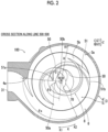
- the suction port 30 of the present embodiment is formed by an arc and a portion protruding to (located on) the inner periphery side in the radial direction from the arc, when viewed from below.
- the inner peripheral wall that forms the suction port 30 includes the suction port protrusion portion 50 provided at a portion thereof in the rotation direction of the rotating shaft 1.
- the suction port protrusion portion 50 is disposed along the second end face 82 (the leading edge) of the vane portion 8 with a slight gap from the second end face 82.
- the suction port protrusion portion 50 is inclined along the inclined second end face 82 of the impeller 6 and protrudes toward the inner periphery side (the center side) in the radial direction of the suction port 30 (refer to FIG. 1 ).
- the suction port protrusion portion 50 protrudes toward the rotating shaft 1 when viewed from below.
- the inclination angle of the suction port protrusion portion 50 is about 45 degrees with respect to the horizontal plane (refer to FIGS. 1 and 4 ). That is, the inclination angle of the suction port protrusion portion 50 is substantially the same as the inclination angle of the second end face 82.
- the suction port protrusion portion 50 is formed in an angular range ⁇ 1 of 45 degrees or larger around the rotating shaft 1 when viewed from the axial direction of the rotating shaft 1 (the Z direction). More specifically, the suction port protrusion portion 50 is formed in the angular range ⁇ 1 of 90 degrees or larger around the rotating shaft 1 when viewed from the axial direction of the rotating shaft 1 (the Z direction).
- the suction port protrusion portion 50 has two curved side surfaces (edge portions) that bulge outward when viewed from the Z direction.
- the side surface located on the upstream side, out of the two side surfaces of the suction port protrusion portion 50 will be described as an upstream-side side surface 50a
- the side surface located on the downstream side will be described as a downstream-side side surface 50b.
- the upstream-side side surface 50a is configured to overlap the rotating vane portion 8 prior to the downstream-side side surface 50b when viewed from the Z direction.
- the inner periphery-side end portion 50c of the suction port protrusion portion 50, to which the upstream-side side surface 50a and the downstream-side side surface 50b are connected, is formed so as to be an arc of a concentric circle centered on the rotation center axis ⁇ .
- the non-clogging pump 100 is configured to suck the foreign matter from between the upstream-side side surface 50a and the rotating vane portion 8 by utilizing the push-in force.
- the inner periphery-side end portion 50c of the suction port protrusion portion 50 is disposed on the inner periphery side in the radial direction (the R direction) with respect to the inner periphery-side end portion 80 of the vane portion 8 which is connected to the main plate protrusion portion 70 of the impeller 6. That is, the inner periphery-side end portion 50c of the suction port protrusion portion 50 is disposed at a position closer to the rotation center axis ⁇ of the rotating shaft 1 than the inner periphery-side end portion 80 of the vane portion 8.
- the inner periphery-side end portion 50c (the lower end) in the counter-inflow direction of the suction port protrusion portion 50 is disposed between the apex 73a (an end point on the lower side) on the counter-inflow direction side of the inclined surface 73 of the impeller 6 and a point 73b (an end point of the upper side) that is located at the bottom on the opposite direction side to the counter-inflow direction of the inclined surface 73, in the axial direction of the rotating shaft 1 (the Z direction).
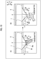
- the inner periphery-side end portion 50c in the counter-inflow direction of the suction port protrusion portion 50 is disposed close to the main plate protrusion portion 70 (the tubular portion 72). That is, the inner periphery-side end portion 50c of the suction port protrusion portion 50 is disposed with a slight gap between itself and the tubular portion 72. Therefore, the inner periphery-side end portion 50c in the counter-inflow direction of the suction port protrusion portion 50 alternately repeats approach (a distance becomes relatively small) and separation (a distance becomes relatively large) with respect to the tubular portion 72 having an inclined surface 73 when the impeller 6 (the tubular portion 72 having the inclined surface 73) rotates (refer to FIG. 13 ).
- the term "approach” refers to a state where the side surface 72a of the tubular portion 72 of the impeller 6 and the inner periphery-side end portion 50c of the suction port protrusion portion 50 face each other in the horizontal direction at a predetermined rotation position of the impeller 6.
- the term “separation” refers to a state where the inclined surface 73 of the impeller 6 and the inner periphery-side end portion 50c of the suction port protrusion portion 50 face each other in the horizontal direction at a predetermined rotation position of the impeller 6. In short, the gap between the inner periphery-side end portion 50c of the suction port protrusion portion 50 and the impeller 6 in the horizontal direction is alternately extended and reduced in association with the rotation of the impeller 6.
- the suction port protrusion portion 50 is disposed at a position closer to the apex 73a (the end point on the lower side) on the counter-inflow direction side of the inclined surface 73 of the impeller 6 than the point 73b (the end point on the upper side) located on the bottom on the opposite direction side to the counter-inflow direction of the inclined surface 73 in the direction (the horizontal direction) orthogonal to the axial direction of the rotating shaft 1 (refer to FIG. 1 ).
- the suction port protrusion portion 50 is disposed at a position closer to the point 73b than the apex 73a in the direction (the horizontal direction) orthogonal to the axial direction of the rotating shaft 1 (refer to FIG. 1 ).
- the upstream-side side surface 50a of the suction port protrusion portion 50 is disposed in an angular range ⁇ a between the tongue portion 4a of the pump casing 3 and the angular position on the upstream side (the upstream side in a flow direction of water in the pump chamber 3a) by 120 degrees from the tongue portion 4a.
- the non-clogging pump 100 is configured to be capable of sucking the foreign matter from the vicinity of the upstream-side side surface 50a of the suction port protrusion portion 50 disposed at a position relatively close to the tongue portion 4a through the suction port 30. As a result, the non-clogging pump 100 can transport the sucked foreign matter to the discharge port 31 through a path of a relatively short distance.
- the upstream-side side surface 50a of the suction port protrusion portion 50 is more preferably disposed in an angular range 8b between the tongue portion 4a of the pump casing 3 and the angular position on the upstream side (the upstream side in the flow direction of water in the pump chamber 3a) by 90 degrees from the tongue portion 4a.
- the pump casing 3 (the suction cover 5) has the foreign matter discharge groove 51.
- the foreign matter discharge groove 51 is provided on the facing surface 5b (the upper surface) on the counter-inflow direction side (the Z2 direction side) of the impeller 6, which faces the impeller 6.
- the foreign matter discharge groove 51 has an elongated shape extending from the inner periphery side in the radial direction (the R direction) toward the outer periphery side.
- the foreign matter discharge groove 51 has a shape in which the cross section in the circumferential direction is half of a substantially teardrop shape.
- the foreign matter discharge groove 51 is formed so as to gradually increase in the rotation direction (the K1 direction) of the impeller 6 from the inner periphery side in the radial direction toward the outer periphery side. That is, the foreign matter discharge groove 51 is formed such that the width of the foreign matter discharge groove 51 increases and R of the bottom surface becomes gentle from the inner periphery side in the radial direction toward the outer periphery side.
- the pump casing 3 (the suction cover 5) includes the facing surface 5b that surrounds the suction port 30, faces the impeller 6 from the suction port 30 side, and extends in the direction substantially orthogonal to the axial direction of the rotating shaft 1.
- the foreign matter discharge groove 51 is provided in the facing surface 5b.
- the edge portion 51c that changes the angle at which the foreign matter discharge groove 51 extends is provided in the vicinity of the boundary portion between the suction port protrusion portion 50 and the facing surface 5b when viewed from the axial direction of the rotating shaft 1.
- the edge portion 51c on the upstream side in the rotation direction of the impeller changes from the upstream side toward the downstream side by an angle of a predetermined angle ⁇ 10 with respect to a tangent line to the foreign matter discharge groove 51 formed in the suction port protrusion portion 50 when viewed from the axial direction of the rotating shaft 1.
- the edge portion 51c on the downstream side in the rotation direction of the impeller changes from the upstream side toward the downstream side by an angle of a predetermined angle ⁇ 11 with respect to a tangent line to the foreign matter discharge groove 51 formed in the suction port protrusion portion 50 when viewed from the axial direction of the rotating shaft 1.
- the predetermined angle ⁇ 10 is 32.5 degrees and the predetermined angle ⁇ 11 is 21.2 degrees.
- an end portion 51a on the inner periphery side in the radial direction of the foreign matter discharge groove 51 extends to the suction port protrusion portion 50.
- An end portion 51b on the outer periphery side in the radial direction of the foreign matter discharge groove 51 is located on the outer periphery side with respect to the vane portion 8 in the radial direction (the R direction). That is, the foreign matter discharge groove 51 extends to the outer periphery side with respect to the gap (slight gap) between the vane portion 8 where a constraint occurs and the facing surface 5b of the suction cover 5 in the radial direction (the R direction).
- the foreign matter discharge groove 51 extends from the inner periphery side in the radial direction (the R direction) toward the outer periphery side so as to swirl along the rotation direction (the K1 direction) of the impeller 6.
- the foreign matter discharge groove 51 has a curved shape along the flow direction of a swirling flow that is generated in the pump chamber 3a with the rotation of the rotating shaft 1 (a swirling spiral flow that is generated with the rotation of the impeller 6).
- only one foreign matter discharge groove 51 is provided in the pump casing 3.
- the foreign matter discharge groove 51 has a function of restraining the foreign matter from being constrained between the vane portion 8 and the pump casing 3. Therefore, the non-clogging pump 100 can reliably transport the foreign matter through the discharge port 31 by the foreign matter discharge groove 51.
- the foreign matter discharge groove 51 is configured to gradually become deeper along the rotation direction of the impeller 6 toward the downstream side from the upstream side in the rotation direction of the impeller 6.
- the outer portion on the lower side of the suction port 30 of the pump casing 3 (the suction cover 5) is formed in a smooth shape along the flow of the swirling flow so as not to obstruct the flow of the swirling flow.
- the suction cover 5 is provided with a recessed portion 5a that is recessed from below to above.
- the recessed portion 5a is disposed in the lower portion of the suction cover 5 (on the outer side of the pump chamber 3a).
- the recessed portion 5a surrounds the suction port 30.
- the recessed portion 5a is provided with a plurality of first protrusion portions 52 that protrude toward the inner periphery side in the radial direction (the R direction) when viewed from below.
- the first protrusion portion 52 is formed in order to secure an installation location for a member for mounting the suction cover 5 to the pump casing main body 4.
- the first protrusion portions 52 are disposed at equal angular intervals (120 degree intervals) in the circumferential direction of the rotating shaft 1.
- the upstream side in the rotation direction is inclined at a relatively small angle ⁇ 2 with respect to the outer peripheral surface of the recessed portion 5a when viewed from below.
- the first protrusion portion 52 is inclined at an angle ⁇ 2 of 30 degrees or smaller in the rotation direction of the impeller 6 with respect to the outer peripheral surface of the recessed portion 5a when viewed from below.
- the first protrusion portion 52 is inclined at an angle ⁇ 2 of 28 degrees with respect to the outer peripheral surface of the recessed portion 5a when viewed from below.
- the recessed portion 5a is provided with a second protrusion portion 53 that extends in the radial direction and protrudes downward, when viewed from below.
- the second protrusion portion 53 is disposed between the outer peripheral surface of the recessed portion 5a and the suction port protrusion portion 50 so as to connect the outer peripheral surface of the recessed portion 5a and the suction port protrusion portion 50.
- the second protrusion portion 53 is formed in a rib shape. By forming the second protrusion portion 53 in this manner, it is possible to improve the strength of the suction port protrusion portion 50.
- the upstream side in the rotation direction is inclined at a relatively small angle ⁇ 3 with respect to the bottom surface (the surface on the upper side) of the recessed portion 5a when viewed from below.
- the second protrusion portion 53 is inclined at an angle ⁇ 3 of 30 degrees or smaller with respect to the bottom surface of the recessed portion 5a when viewed from below.
- the second protrusion portion 53 is inclined at an angle ⁇ 3 of 30 degrees with respect to the bottom surface of the recessed portion 5a when viewed from below.
- the vane portion 8 is configured to include the first end face 81 that is an end face in the counter-inflow direction (the Z2 direction), which is located on the outer periphery side in the radial direction (the R direction) of the rotating shaft 1, and extends in the direction intersecting the counter-inflow direction, and the second end face 82 (the leading edge) that is an end face in the counter-inflow direction, which is connected to the first end face 81 from the inner periphery side in the radial direction of the first end face 81 and located on the inner periphery side in the radial direction, and is inclined with respect to the first end face 81 so as to be located on the counter-inflow direction side toward the inner periphery side in the radial direction.
- the gap between a flow straightener and a pump main body is not clogged with soft foreign matter, and thus it is possible to improve the passage performance of the foreign matter. As a result, it is possible to improve the passage performance of the foreign matter without complicating a device configuration.
- the two or more vane portions 8 it is possible to dispose the two or more vane portions 8 in a well-balanced manner around the rotating shaft 1, and therefore, compared to a case where only one vane portion 8 is provided, it is possible to reduce vibration associated with the rotation of the impeller 6. Therefore, it is possible to suppress a decrease in pump efficiency.
- the main plate portion 7 is provided with the main plate protrusion portion 70 that protrudes in the counter-inflow direction toward the inner periphery side in the radial direction of the rotating shaft 1, and the suction port protrusion portion 50 that protrudes to the center side of suction port 30 is provided on the inner peripheral wall that forms the suction port 30 of the pump casing 3. Due to the suction port protrusion portion 50, the center of the swirling flow (the spirally swirling flow that is generated by the rotation of the impeller 6) that is generated in the vicinity of the suction port 30 can be made to be eccentric when viewed from the axial direction of the rotating shaft 1, and therefore, the center of the swirling flow can be shifted from the main plate protrusion portion 70.
- the foreign matter can be sucked in at an angle with respect to the direction of the rotating shaft.
- the opening area of the suction port 30 is reduced due to the suction port protrusion portion 50, so that it is possible to increase the suction speed of water and the foreign matter. Therefore, it is possible to suppress a decrease in suction flow velocity even in a small water volume range.
- the angle formed by the second end face 82 and the first end face 81 is an obtuse angle. In this way, it is possible to cause the second end face 82 to protrude toward the suction port 30 side with respect to the first end face 81, and therefore, by the second end face 82, it is possible to crush and cut the foreign matter (rubber gloves, stockings, or the like in a state of being caught in a tip clearance (a gap between the first end face 81 of the vane portion 8 and the surface of the pump casing 3 facing the first end face 81)) that stays across the suction port 30 due to being caught in the end face of the vane portion 8. In this way, it is possible to prevent the foreign matter from being constrained by the tip clearance across the suction port 30.
- the suction port protrusion portion 50 is formed in an angular range of 45 degrees or larger around the rotating shaft 1 when viewed from the axial direction of the rotating shaft 1. In this way, the suction port protrusion portion 50 can be provided in a relatively large angular range, and therefore, the center of the swirling flow that is generated in the vicinity of the suction port 30 can be reliably made to be eccentric. As a result, it is possible to effectively restrain the foreign matter from being entangled in the main plate protrusion portion 70.
- the suction port protrusion portion 50 since it is possible to cause the suction port protrusion portion 50 to protrude from a relatively large angular range, the opening area of the suction port 30 can be reduced due to the suction port protrusion portion 50, and thus it is possible to further increase the suction speed of water and the foreign matter. Therefore, it is possible to further suppress a decrease in suction flow velocity even in a small water volume range. Further, since the suction port protrusion portion 50 is formed in a relatively wide angular range, it is possible to restrain soft foreign matter from being entangled in and constrained by the suction port protrusion portion 50.
- the inner periphery-side end portion 50c of the suction port protrusion portion 50 is disposed on an inner periphery side in the radial direction of the rotating shaft 1 with respect to the inner periphery-side end portion 80 of the vane portion 8, which is connected to the main plate protrusion portion 70, or a position substantially corresponding to the inner periphery-side end portion 80 of the vane portion 8 in the radial direction.
- the suction port protrusion portion 50 it is possible to cause the suction port protrusion portion 50 to protrude to the vicinity of the main plate protrusion portion 70, and therefore, when the vane portion 8 passes near the suction port protrusion portion 50, the foreign matter can be reliably removed by the suction port protrusion portion 50. As a result, it is possible to prevent the foreign matter from being stacked on the second end face 82. Further, the foreign matter can be cut and crushed to a size in which the foreign matter is not caught in the tongue portion 4a, the outer periphery of the vane portion 8, and the tip clearance.
- the main plate protrusion portion 70 has, at a tip thereof, the inclined surface 73 inclined with respect to the direction orthogonal to the counter-inflow direction.
- the inclined surface 73 is configured such that when the impeller 6 rotates, the inclined surface 73 rotates and a force that pushes the foreign matter to the top portion of the inclined surface 73 along the inclined surface 73 can be applied to the foreign matter.
- the force acting on the foreign matter in the inflow direction can be made non-uniform, and therefore, in a case where the foreign matter is entangled in the inclined surface 73, the foreign matter is out of balance and can be removed from the inclined surface 73.
- the tip of the main plate protrusion portion 70 has a substantially circular shape when viewed from the axial direction of the rotating shaft 1. In this way, the top portion of the inclined surface 73 is formed to be round, and therefore, the effect of removing the foreign matter from the inclined surface 73 is enhanced.
- the inclined surface 73 is provided on the entire tip of the main plate protrusion portion 70. In this way, when the inclined surface 73 rotates, a larger force that pushes the foreign matter to the top portion of the inclined surface 73 along the inclined surface 73 can be applied to the foreign matter. Therefore, in a case where the foreign matter is entangled in the inclined surface 73, the balance of the foreign matter can be more greatly disturbed, and therefore, it is possible to effectively remove the foreign matter from the inclined surface 73.
- the apex 73a on the counter-inflow direction side of the inclined surface 73 is disposed at a substantially intermediate position between the two vane portions 8 that are located in the vicinity of the apex 73a in the rotation direction of the rotating shaft 1.
- both the distance between the top portion and the vane portion 8 on one side and the distance between the top portion and the vane portion 8 on the other side can be reduced (substantially minimized), and therefore, after the foreign matter is removed from the inclined surface 73, it can be quickly crushed by the vane portion 8 and the suction port protrusion portion 50 and pushed into the suction port 30.
- the passage performance of the foreign matter can be further improved.
- the inner periphery-side end portion 50c in the counter-inflow direction of the suction port protrusion portion 50 is disposed close to the side surface of the main plate protrusion portion 70 when viewed from the axial direction of the rotating shaft 1.
- the main plate protrusion portion 70 and the suction port protrusion portion 50 can be disposed with a narrow (small) gap, and therefore, the foreign matter can be effectively cut and crushed in the gap between the main plate protrusion portion 70 and the suction port protrusion portion 50, and the foreign matter can be more effectively removed from the inclined surface 73 of the impeller 6.
- the inner periphery-side end portion 50c in the counter-inflow direction of the suction port protrusion portion 50 is disposed between the apex 73a on the counter-inflow direction side of the inclined surface 73 and the point 73b that is located on the bottom on the opposite direction side to the counter-inflow direction of the inclined surface 73, in the axial direction of the rotating shaft 1.
- the side surface of the formed inclined surface 73 has a non-uniform length in the direction of the rotating shaft (the Z direction), and therefore, the inner periphery-side end portion 50c of the suction port protrusion portion 50 and the side surface 72a of the main plate protrusion portion 70 (the tubular portion 72) smoothly repeat “approach” and “separation” with the rotation of the impeller 6, so that the foreign matter is easily removed from the inclined surface 73 of the impeller 6. As a result, the passage performance of the foreign matter can be further improved.
- the inner periphery-side portion in the radial direction (of the rotating shaft 1) of the vane portion 8 is inclined to be located so as to spread to the outer periphery side in the radial direction toward the counter-inflow direction.
- the vane portion 8 is formed in a so-called screw shape. Therefore, a force that pushes foreign matter into the impeller 6 can act on the foreign matter with the rotation of the impeller 6, and therefore, the foreign matter is easily removed from the gap between the suction port protrusion portion 50 and the vane portion 8. As a result, the passage performance of the foreign matter can be further improved.
- the pump casing 3 has the foreign matter discharge groove 51 that has an elongated shape, is provided on the facing surface 5b on the counter-inflow direction side of the impeller 6, which faces the impeller 6, and extends from the inner periphery side toward the outer periphery side in the radial direction of the rotating shaft 1, and the end portion 51a on the inner periphery side in the radial direction of the foreign matter discharge groove 51 extends to the suction port protrusion portion 50.
- the pump casing 3 includes the facing surface 5b that surrounds the suction port 30, faces the impeller 6 from the suction port 30 side, and extends in the direction substantially orthogonal to the axial direction of the rotating shaft 1, the foreign matter discharge groove 51 is provided on the facing surface 5b, and the foreign matter discharge groove 51 is provided with the edge portion 51c, which changes an angle at which the foreign matter discharge groove 51 extends, in the vicinity of the boundary portion between the suction port protrusion portion 50 and the facing surface 5b when viewed from the axial direction of the rotating shaft 1. In this way, the foreign matter is caught in the edge portion 51c, and the vane portion 8 of the impeller 6 passes over the foreign matter caught in the edge portion 51c, so that the foreign matter can be cut.
- the end portion 51b on the outer periphery side in the radial direction of the foreign matter discharge groove 51 is located on the outer periphery side with respect to the vane portion 8 in the radial direction. In this way, due to the foreign matter discharge groove 51, the foreign matter can be led to the outside of the gap between the first end face 81 of the vane portion 8 (the impeller 6) and the facing surface 5b of the pump casing 3, which faces the first end face 81 of the vane portion 8, and therefore, the passage performance of the foreign matter can be further improved.
- the foreign matter discharge groove 51 is configured to become deeper toward the downstream side from the upstream side in the rotation direction of the impeller 6 along the rotation direction of the impeller 6. In this way, the foreign matter can be effectively pushed into the foreign matter discharge groove 51 along the rotation direction of the impeller 6, and therefore, the passage performance of the foreign matter can be further improved.
- the foreign matter discharge groove 51 is configured to widen in width toward the outer periphery from the center of the pump casing 3. In this way, the foreign matter discharge groove 51 is gradually widened in the discharge direction, and therefore, the effect of pushing out the foreign matter in the discharge direction can be obtained.
- the upstream-side side surface 50a of the suction port protrusion portion 50 is disposed in the angular range between the tongue portion 4a of the pump casing 3 and the angular position on the upstream side by 120 degrees with respect to the tongue portion 4a.
- the upstream-side side surface 50a which is located at a position where the foreign matter is easily pushed into the pump chamber, can be disposed at a position relatively close to the tongue portion 4a.
- the sucked foreign matter can be immediately discharged with a time when it is present in the pump chamber 3a (volute) shortened. Therefore, it is possible to make it difficult for the foreign matter to be entangled in the tongue portion 4a, the impeller 6, or the like. As a result, the passage performance of the foreign matter can be further improved.
- the impeller 6 is configured such that the flow path S1 on the negative pressure surface 83a side of the vane portion 8 is narrower than the flow path S2 on the pressure surface 83b side of the vane portion 8 on the main plate portion 7 side and the inner periphery side in the radial direction.
- the flow path S1 on the negative pressure surface 83a side by narrowing the flow path S1 on the negative pressure surface 83a side, the stay of the sucked foreign matter in the flow path S1 on the negative pressure surface 83a side is suppressed, and the foreign matter can be pushed into (be brought near) the flow path S2 on the pressure surface 83b side. That is, it is possible to easily discharge the foreign matter. As a result, the passage performance of the foreign matter can be further improved.
- the main plate portion 7 is provided with the weight portion 71 having an annular shape and applying an inertial force to the impeller 6.
- the inertial force of the rotating impeller 6 can be increased, and therefore, an increase in torque due to the crushing of the foreign matter and an impact can be canceled out.
- the flywheel effect is an effect of making the rotation speed of a rotating body rotating around a predetermined axis as uniform as possible (an effect of eliminating unevenness of the rotation speed of the rotating body).
- the thickness on the outer periphery side in the radial direction of the vane portion 8 is larger than the thickness on the inner periphery side in the radial direction of the vane portion 8. In this way, due to the flywheel effect that is obtained by the vane portion 8, the inertial force of the rotating impeller 6 can be increased, and therefore, an increase in torque due to the crushing of the foreign matter and an impact can be canceled out. Further, it is possible to obtain the flywheel effect by the vane portion 8 that is an existing configuration.
- the non-clogging pump further includes the electric motor 2 that rotates the rotating shaft 1, and the non-clogging pump is configured such that the rotational frequency of the electric motor 2 is changeable, and is configured such that in a case where the drive power value of the electric motor 2 falls below a predetermined first threshold value, the rotational frequency of the electric motor 2 is increased until the drive power value of the electric motor 2 reaches the predetermined first threshold value or the predetermined second threshold value exceeding the predetermined first threshold value.
- the span for crushing the foreign matter can be shortened by increasing the rotational frequency of the electric motor 2, and therefore, the foreign matter can be crushed finely.
- the non-clogging pump further includes the electric motor 2 that rotates the rotating shaft 1, and the non-clogging pump is configured such that in a case where a state where the drive power value of the electric motor 2 exceeds the drive power reference value is continued for a predetermined time or longer, the driving of the electric motor 2 is stopped, and the impeller 6 is rotated in a reverse direction when it is repeatedly determined that the state where the drive power value of the electric motor 2 exceeds the drive power reference value is continued for a predetermined time or longer, even if restart is attempted by a predetermined number of times.
- the non-clogging pump 100 can effectively remove the foreign matter entangled in the impeller 6, the foreign matter constrained in the pump chamber 3a, or the like.
- the suction port protrusion portion 50 and a recessed portion 201 may be provided in the suction port 30, as in a non-clogging pump 200 of the modification example shown in FIG. 15 .
- the inner peripheral wall that forms the suction port 30 of the pump casing 3 further includes, in addition to the suction port protrusion portion 50, the recessed portion 201 that is provided on the side opposite to the side where the suction port protrusion portion 50 is disposed, with respect to the rotating shaft 1 when viewed in a plan view, and recessed to the outer periphery side in the radial direction of the suction port 30.
- the recessed portion 201 (the area of the portion recessed with respect to the arc of the suction port 30) is formed to be smaller than the suction port protrusion portion 50.
- the center of the swirling flow that is generated in the vicinity of the suction port 30 can be made to be more eccentric, compared to a case where only the suction port protrusion portion 50 is provided. Therefore, it is possible to further suppress the entanglement of the foreign matter in the main plate protrusion portion 70 (refer to FIG. 1 ). As a result, the passage performance of the foreign matter can be further improved. Further, in a case where relatively large foreign matter flows in, the foreign matter can be cut and crushed by the recessed portion 201.
- the recessed portion 201 due to the recessed portion 201, even if large foreign matter flows in, the foreign matter is moved to the recessed portion 201, and the foreign matter can be crushed to a size that allows passage, by "cutting action and crushing action” due to a change in the relative position between the downstream-side side wall in the rotation direction of the recessed portion 201 (the rotation direction of the impeller 6) and the pressure surface-side edge of the leading edge (the second end face 82) of the rotating vane portion 8.
- the non-clogging pump is a vertical type submersible electric pump.
- the present invention is not limited to this.
- the non-clogging pump may be a horizontal type submersible electric pump.
- a vertical type submersible electric pump in which a motor is disposed on the lower side and a pump casing is disposed on the upper side may be adopted.
- the drive source of the non-clogging pump is configured with a motor.
- the present invention is not limited to this.
- the drive source may be configured with an engine.
- the pump may be configured as a submersible electric pump in which a float is mounted to the pump to float the pump in water, a motor faces downward, and a suction port faces upward.
- the present invention is not limited to this.
- a plurality of foreign matter discharge grooves may be provided in the pump casing.
- the example is shown in which a configuration is made such that the depth of the foreign matter discharge groove gradually increases toward the downstream side from the upstream side in the rotation direction of the impeller.
- the present invention is not limited to this.
- a configuration may be made such that the depth of the foreign matter discharge groove gradually decreases toward the downstream side from the upstream side in the rotation direction of the impeller.
- the example is shown in which a configuration is made such that the depth of the foreign matter discharge groove gradually increases toward the downstream side from the upstream side in the rotation direction of the impeller.
- the present invention is not limited to this.
- a configuration may be made such that the depth of the foreign matter discharge groove is changed from the inner periphery side toward the outer periphery side.
- the impeller includes two vane portions.
- the present invention is not limited to this.
- the impeller may include three or more vane portions.
- the upstream-side side surface of the suction port protrusion portion is disposed in an angular range between the tongue portion of the pump casing and the angular position on the upstream side by 120 degrees (in the K2 direction) with respect to the tongue portion.
- the present invention is not limited to this.
- the upstream-side side surface of the suction port protrusion portion may be disposed at an angular position on the upstream side by an angle larger than 120 degrees (in the K2 direction) with respect to the tongue portion of the pump casing.
- the first end face is formed so as to extend in a substantially horizontal direction.
- the present invention is not limited to this.
- the first end face may be formed so as to be inclined with respect to the horizontal direction.
- the first end face may be inclined with respect to the horizontal direction such that the inner periphery side in the radial direction is located in the counter-inflow direction (the downward direction).
- the first end face is inclined at an angle of 15 degrees or smaller with respect to the horizontal direction.
- the first end face is inclined such that the angle formed by the first end face and the second end face is an obtuse angle.
- the suction port protrusion portion is formed in an angular range of 45 degrees or larger around the rotating shaft when viewed from the axial direction of the rotating shaft.
- the present invention is not limited to this.
- the suction port protrusion portion may be formed in an angular range of less than 45 degrees around the rotating shaft when viewed from the axial direction of the rotating shaft.
- the pump casing is composed of two members, that is, the pump casing and the suction cover is shown.
- the present invention is not limited to this.
- the pump casing may be configured with only one member that is the pump casing main body. In this case, both the suction port and the discharge port are provided in the pump casing main body.
- the tip (the end portion on the lower side) of the main plate protrusion portion has a circular shape when viewed from below.
- the present invention is not limited to this.
- the tip (the end portion on the lower side) of the main plate protrusion portion may have a shape different from the circular shape, such as a rectangular shape or a gear shape, when viewed from below.
- the example is shown in which the second end face (the first end face) of the vane portion is formed so as to be flat when viewed in a side view.
- the present invention is not limited to this.
- the second end face (the first end face) of the vane portion may be formed so as to be curved when viewed in a side view.
- the example is shown in which the inner periphery-side end portion of the suction port protrusion portion is disposed on the inner periphery side in the radial direction of the rotating shaft with respect to the inner periphery-side end portion of the vane portion, which is connected to the main plate protrusion portion.
- the present invention is not limited to this.
- the inner periphery-side end portion of the suction port protrusion portion may be disposed at a position substantially corresponding to the inner periphery-side end portion of the vane portion in the radial direction.
- the example is shown in which the inclination angle of the inclined surface with respect to the horizontal plane is smaller than 45 degrees.
- the present invention is not limited to this.
- the inclination angle of the inclined surface with respect to the horizontal plane may be 45 degrees or larger.
Landscapes
- Engineering & Computer Science (AREA)
- Mechanical Engineering (AREA)
- General Engineering & Computer Science (AREA)
- Physics & Mathematics (AREA)
- Geometry (AREA)
- Structures Of Non-Positive Displacement Pumps (AREA)
Claims (16)
- Eine verstopfungsfreie Pumpe (100, 200) zum Pumpen von Fluid, das Fremdstoffe enthält, wobei die verstopfungsfreie Pumpe (100, 200) umfasst:ein Pumpengehäuse (3), das mit einer Saugöffnung (30) versehen ist; undeinen Impeller (6), der einen Hauptplattenabschnitt (7) und zwei oder mehr Schaufelabschnitte (8) enthält, die auf einer Saugöffnungsseite des Hauptplattenabschnitts (7) angeordnet sind, an einem Ende (1a) einer Drehwelle (1) befestigt ist und innerhalb des Pumpengehäuses (3) angeordnet ist,wobei der Hauptplattenabschnitt (7) einen Hauptplattenvorsprungsabschnitt (70) enthält, der in einer Gegeneinströmrichtung, die eine Richtung entgegengesetzt zu einer Einströmrichtung von Wasser von der Saugöffnung (30) ist, die im Wesentlichen mit einer Axialrichtung der Drehwelle (1) übereinstimmt, in Richtung einer Innenperipherieseite in einer Radialrichtung der Drehwelle (1) vorsteht,wobei der Schaufelabschnitt (8) eine erste Endfläche (81), die eine Endfläche in der Gegeneinströmrichtung ist, die auf einer Außenperipherieseite in der Radialrichtung gelegen ist und sich in einer Richtung erstreckt, die die Gegenströmungsrichtung schneidet, und eine zweite Endfläche (82) enthält, die eine Endfläche in der Gegeneinströmrichtung ist, die mit der ersten Endfläche (81) von der Innenperipherieseite in Radialrichtung der ersten Endfläche verbunden ist und auf der Innenperipherieseite in Radialrichtung gelegen ist und in Bezug auf die erste Endfläche (81) so geneigt ist, dass sie auf einer Gegeneinströmrichtungsseite in Richtung der Innenperipherieseite in der Radialrichtung gelegen ist, und mit dem Hauptplattenvorsprungabschnitt an einem Innenperipherieseitenendabschnitt (80) verbunden ist, undeine Innenperipheriewand, die die Saugöffnung des Pumpengehäuses bildet, einen Saugöffnungsvorsprung (50) enthält, der an einem Abschnitt in einer Drehrichtung der Drehwelle vorgesehen ist, entlang der zweiten Endfläche mit einem Spalt von der zweiten Endfläche angeordnet ist und in Richtung einer Zentrumsseite der Saugöffnung vorsteht,dadurch gekennzeichnet, dass der Hauptplattenvorsprungsabschnitt (70) an einer Spitze davon eine geneigte Oberfläche (73) aufweist, die in Bezug auf eine Richtung orthogonal zur Gegeneinströmrichtung geneigt ist, wobei die geneigte Oberfläche (73) so konfiguriert ist, dass, wenn sich der Impeller (6) dreht, die geneigteOberfläche sich dreht und eine Kraft, die den Fremdkörper entlang der geneigten Oberfläche zum oberen Abschnitt der geneigten Oberfläche drückt, auf den Fremdkörper ausgeübt werden kann.
- Die verstopfungsfreie Pumpe nach Anspruch 1,
wobei ein Winkel, der durch die zweite Endfläche (82) und die erste Endfläche (81) gebildet wird, ein stumpfer Winkel ist. - Die verstopfungsfreie Pumpe nach Anspruch 1 oder 2,
wobei der Saugöffnungsvorsprungsabschnitt (50) in einem Winkelbereich von 45 Grad oder mehr um die Drehwelle (1) herum ausgebildet ist, von der Axialrichtung der Drehwelle aus gesehen. - Die verstopfungsfreie Pumpe nach einem der Ansprüche 1 bis 3,
wobei der Innenperipherieseitenendabschnitt (50c) des Saugöffnungsvorsprungsabschnitts (50) auf der Innenperipherieseite in der Radialrichtung in Bezug auf den Innenperipherieseitenendabschnitt des Schaufelabschnitts (8), der mit dem Hauptplattenvorsprungsabschnitt (70) verbunden ist, angeordnet ist, oder an einer Position, die in der Radialrichtung im Wesentlichen dem Innenperipherieseitenendabschnitt des Schaufelabschnitts (8) entspricht. - Die verstopfungsfreie Pumpe nach irgendeinem der Ansprüche 1 bis 4,
wobei die Spitze des Hauptplattenvorsprungsabschnitts (70) in der Axialrichtung der Drehwelle gesehen eine im Wesentlichen kreisförmige Form aufweist. - Die verstopfungsfreie Pumpe nach irgendeinem der Ansprüche 1 bis 5,
wobei die geneigte Oberfläche (73) an einer gesamten Spitze des Hauptplattenvorsprungabschnitts (70) vorgesehen ist. - Die verstopfungsfreie Pumpe nach irgendeinem der Ansprüche 1 bis 6,
wobei der Innenperipherieseitenendabschnitt in der Gegeneinströmrichtung des Saugöffnungsvorsprungsabschnitts (50) nahe einer Seitenfläche des Hauptplattenvorsprungsabschnitts (70) angeordnet ist, von der Axialrichtung der Drehwelle aus gesehen. - Die verstopfungsfreie Pumpe nach irgendeinem der Ansprüche 1 bis 7,
wobei der Innenperipherieseitenendabschnitt in der Gegeneinströmrichtung des Saugöffnungsvorsprungsabschnitts (50) zwischen einem Apex (73a) auf der Gegeneinströmrichtungsseite der geneigten Oberfläche (73) und einem Punkt (73b), der auf einer Unterseite auf einer der Gegeneinströmrichtung der geneigten Oberfläche (73) entgegengesetzten Richtungsseite gelegen ist, angeordnet ist, in der Axialrichtung der Drehwelle (1) gesehen. - Die verstopfungsfreie Pumpe nach irgendeinem der Ansprüche 1 bis 8,
wobei ein Innenperipherieseitenabschnitt in der Radialrichtung des Schaufelbereichs (8) so geneigt ist, dass er sich in der Radialrichtung zur Gegeneinströmrichtung hin zur Außenperipherieseite hin ausbreitet. - Die verstopfungsfreie Pumpe nach irgendeinem der Ansprüche 1 bis 9,wobei das Pumpengehäuse (3) eine Fremdkörperauslassnut (51) aufweist, die eine längliche Form hat, an einer zugewandten Oberfläche (5b) auf Gegeneinströmrichtungsseite des Impellers (6) vorgesehen ist, die dem Impeller (6) zugewandt ist, und sich in der Radialrichtung von der Innenperipherieseite zur Außenperipherieseite erstreckt, undein Endabschnitt (51a) auf der Innenperipherieseite in der Radialrichtung der Fremdkörperauslassnut (51) sich bis zum Saugöffnungsvorsprungabschnitt (50) erstreckt.
- Die verstopfungsfreie Pumpe nach Anspruch 10,wobei das Pumpengehäuse (3) die zugewandte Oberfläche enthält, die die Saugöffnung umgibt, von der Saugöffnungsseite aus dem Impeller (6) zugewandt ist und sich in einer Richtung im Wesentlichen orthogonal zur Axialrichtung der Drehwelle (1) erstreckt, wobei die Fremdkörperauslassnut (51) auf der zugewandten Oberfläche vorgesehen ist, unddie Fremdkörperauslassnut (51) mit einem Randabschnitt (51c) versehen ist, der einen Winkel ändert, in dem sich die Fremdkörperauslassnut (51) erstreckt, in der Nähe eines Grenzabschnitts zwischen dem Saugöffnungsvorsprungsabschnitt (50) und der zugewandten Oberfläche, von der Axialrichtung der Drehwelle (1) gesehen.
- Die verstopfungsfreie Pumpe nach irgendeinem der Ansprüche 1 bis 11,
wobei der Impeller (6) so konfiguriert ist, dass ein Strömungspfad (S1) auf einer Seite einer Unterdruckfläche (83a) des Schaufelabschnitts (8) enger ist als ein Strömungspfad (S2) auf einer Seite einer Druckfläche (83b) des Schaufelabschnitts (8) auf einer Hauptplattenabschnittsseite und der Innenperipherieseite in der Radialrichtung. - Die verstopfungsfreie Pumpe nach irgendeinem der Ansprüche 1 bis 12,
wobei der Hauptplattenabschnitt (7) mit einem Gewichtsabschnitt (71) versehen ist, der eine ringförmige Form aufweist und eine Trägheitskraft auf den Impeller (6) ausübt. - Die verstopfungsfreie Pumpe nach irgendeinem der Ansprüche 1 bis 13,
wobei eine Dicke auf der Außenperipherieseite in der Radialrichtung des Schaufelabschnitts (8) größer ist als eine Dicke auf der Innenperipherieseite in der Radialrichtung des Schaufelabschnitts (8). - Die verstopfungsfreie Pumpe nach irgendeinem der Ansprüche 1 bis 14, ferner umfassend: einen Elektromotor (2), der die Drehwelle (1) dreht,
wobei die verstopfungsfreie Pumpe so konfiguriert ist, dass in einem Fall, in dem ein Zustand, in dem ein Antriebsleistungswert des Elektromotors (2) einen Antriebsleistungsreferenzwert überschreitet, für eine vorbestimmte Zeit oder länger andauert, der Impeller (6) in eine umgekehrte Richtung gedreht wird, wenn wiederholt bestimmt wird, dass der Zustand, in dem der Antriebsleistungswert des Elektromotors (2) den Antriebsleistungsreferenzwert überschreitet, für eine vorbestimmte Zeit oder länger andauert, selbst wenn ein Neustart mit dem Elektromotor (2) versucht wird, der durch eine vorbestimmte Anzahl von Malen gestoppt wurde. - Die verstopfungsfreie Pumpe nach irgendeinem der Ansprüche 1 bis 15,
wobei die Innenperipheriewand, die die Saugöffnung des Pumpengehäuses (3) bildet, ferner enthält, zusätzlich zu dem Saugöffnungsvorsprungsabschnitt (50) einen vertieften Abschnitt (201), der auf einer Seite gegenüber einer Seite vorgesehen ist, auf der der Saugöffnungsvorsprungsabschnitt (50) in einer Draufsicht gesehen in Bezug auf die Drehwelle (1) angeordnet ist, und der in der Radialrichtung der Saugöffnung zu einer Außenperipherieseite hin vertieft ist.
Applications Claiming Priority (2)
| Application Number | Priority Date | Filing Date | Title |
|---|---|---|---|
| JP2019213397A JP7276099B2 (ja) | 2019-11-26 | 2019-11-26 | 無閉塞ポンプ |
| PCT/JP2020/042663 WO2021106658A1 (ja) | 2019-11-26 | 2020-11-16 | 無閉塞ポンプ |
Publications (3)
| Publication Number | Publication Date |
|---|---|
| EP4067663A1 EP4067663A1 (de) | 2022-10-05 |
| EP4067663A4 EP4067663A4 (de) | 2024-01-10 |
| EP4067663B1 true EP4067663B1 (de) | 2025-06-18 |
Family
ID=76088169
Family Applications (1)
| Application Number | Title | Priority Date | Filing Date |
|---|---|---|---|
| EP20894890.1A Active EP4067663B1 (de) | 2019-11-26 | 2020-11-16 | Verstopfungsfreie pumpe |
Country Status (8)
| Country | Link |
|---|---|
| US (1) | US12055160B2 (de) |
| EP (1) | EP4067663B1 (de) |
| JP (3) | JP7276099B2 (de) |
| KR (1) | KR102704850B1 (de) |
| CN (1) | CN114729644B (de) |
| ES (1) | ES3036745T3 (de) |
| TW (1) | TWI840632B (de) |
| WO (1) | WO2021106658A1 (de) |
Families Citing this family (6)
| Publication number | Priority date | Publication date | Assignee | Title |
|---|---|---|---|---|
| JP7067443B2 (ja) * | 2018-11-30 | 2022-05-16 | 株式会社鶴見製作所 | 水中ポンプ |
| JP7024822B2 (ja) * | 2020-06-22 | 2022-02-24 | 株式会社鶴見製作所 | 無閉塞ポンプ |
| CN116324176B (zh) * | 2020-10-29 | 2025-12-30 | 伟尔矿物澳大利亚私人有限公司 | 用于离心泵的开槽侧衬套 |
| CN115199588B (zh) * | 2022-08-11 | 2025-01-24 | 浙江理工大学 | 一种具有可升降螺旋结构的立式离心泵吸入室 |
| US12565893B2 (en) * | 2023-06-07 | 2026-03-03 | Zoeller Pump Company, Llc | Reversing polarity of a pump on failure, and applications thereof |
| KR102738215B1 (ko) * | 2023-11-20 | 2024-12-04 | (주)대한중전기 | 공동공간 내에 이물질 침투를 방지하는 리어윙을 구비한 입축 또는 수중 펌프 |
Citations (2)
| Publication number | Priority date | Publication date | Assignee | Title |
|---|---|---|---|---|
| US4402648A (en) * | 1981-08-31 | 1983-09-06 | A. O. Smith Harvestore Products, Inc. | Chopper pump |
| JPS6310288U (de) * | 1986-07-07 | 1988-01-23 |
Family Cites Families (46)
| Publication number | Priority date | Publication date | Assignee | Title |
|---|---|---|---|---|
| US3692422A (en) * | 1971-01-18 | 1972-09-19 | Pierre Mengin Ets | Shearing pump |
| JPS5136721Y2 (de) * | 1973-09-06 | 1976-09-09 | ||
| JPS5136722Y2 (de) * | 1973-09-06 | 1976-09-09 | ||
| JPS5357507A (en) * | 1976-11-04 | 1978-05-24 | Kubota Ltd | Cutter underwater pumps |
| JPS5837992U (ja) * | 1981-09-07 | 1983-03-11 | 株式会社荏原製作所 | 水中サンドポンプ |
| SE444969B (sv) * | 1982-10-11 | 1986-05-20 | Flygt Ab | Centrifugalpump avseddd for pumpning av vetskor innehallande fasta partiklar |
| JPS61162592U (de) * | 1985-03-29 | 1986-10-08 | ||
| JPS6419195A (en) * | 1987-07-14 | 1989-01-23 | Kubota Ltd | Cutting device for grinder pump |
| JP2636966B2 (ja) | 1990-12-20 | 1997-08-06 | 株式会社三興ポンプ製作所 | カッター付下水管用水中ポンプ |
| JPH094585A (ja) * | 1995-06-20 | 1997-01-07 | Torishima Pump Mfg Co Ltd | 汚水ポンプ |
| JP2914902B2 (ja) * | 1995-11-21 | 1999-07-05 | 謙助 冨田 | 水中ポンプ |
| DE19920243A1 (de) * | 1999-05-03 | 2000-11-16 | Weissenhorner Manfred | Dickstoffpumpe |
| HK1050042B (zh) * | 2000-07-19 | 2007-04-27 | 株式会社鹤见制作所 | 使润滑油留在潜水泵油腔内的轴密封装置滑动表面的装置 |
| JP2003011035A (ja) * | 2001-06-29 | 2003-01-15 | Makoto:Kk | クーラント供給装置の浸漬型ポンプ |
| JP2005090313A (ja) | 2003-09-16 | 2005-04-07 | Ebara Corp | 無閉塞ポンプ |
| US8469675B2 (en) * | 2004-08-26 | 2013-06-25 | Pentair Water Pool And Spa, Inc. | Priming protection |
| JP2006257978A (ja) * | 2005-03-17 | 2006-09-28 | Aisin Seiki Co Ltd | 流体ポンプ |
| SE0501382L (sv) * | 2005-06-17 | 2006-06-13 | Itt Mfg Enterprises Inc | Pump för pumpning av förorenad vätska |
| SE527964C2 (sv) | 2005-07-01 | 2006-07-25 | Itt Mfg Enterprises Inc | Pump för att pumpa förorenad vätska inkluderande fast material |
| KR100722507B1 (ko) * | 2005-12-14 | 2007-05-28 | 삼진공업 주식회사 | 이물질 절단장치가 구비된 수중펌프 |
| JP4963836B2 (ja) * | 2006-01-31 | 2012-06-27 | 株式会社クボタ | 渦巻ポンプ装置 |
| CN200943586Y (zh) * | 2006-07-03 | 2007-09-05 | 江苏迎浪科技集团有限公司 | 新型污水处理装置配套智能泵组 |
| JP5132243B2 (ja) * | 2007-10-17 | 2013-01-30 | 株式会社鶴見製作所 | 水中曝気装置 |
| JP5438587B2 (ja) * | 2010-04-16 | 2014-03-12 | 株式会社山田製作所 | ウォーターポンプにおけるインペラ |
| JP2012013269A (ja) * | 2010-06-30 | 2012-01-19 | Hitachi Appliances Inc | 熱交換器、その熱交換器を用いた冷凍サイクル装置、並びに、その冷凍サイクル装置を用いた空気調和機及びヒートポンプ給湯機 |
| DE102011112580B4 (de) * | 2011-09-08 | 2014-03-20 | Schmalenberger Gmbh & Co. Kg | Selbstansaugende Pumpe mit Schneidwerk |
| KR101366892B1 (ko) * | 2012-03-15 | 2014-02-24 | 한세구 | 고효율 펌프 임펠러 |
| JP5916558B2 (ja) * | 2012-08-07 | 2016-05-11 | 株式会社鶴見製作所 | 水中モータポンプ |
| CN203394823U (zh) * | 2013-04-11 | 2014-01-15 | 南京布鲁克林环保设备有限公司 | 一种具有切割功能的潜水排污泵 |
| KR101353776B1 (ko) * | 2013-07-26 | 2014-01-22 | 고일영 | 수중 스크루 펌프용 임펠러 구조 |
| KR101562027B1 (ko) * | 2014-02-04 | 2015-10-20 | 주식회사 한진펌프 | 이물질의 절단이 가능한 수중펌프 |
| JP6415116B2 (ja) * | 2014-05-30 | 2018-10-31 | 株式会社荏原製作所 | 汚水ポンプ用のケーシングライナ及びこれを備えた汚水ポンプ |
| KR101497052B1 (ko) * | 2014-07-18 | 2015-02-27 | 김상국 | 이물질 절단 파쇄 기능을 갖는 수중펌프 |
| JP6512792B2 (ja) * | 2014-11-06 | 2019-05-15 | 株式会社荏原製作所 | 磁気浮上型ポンプ |
| CN104747455A (zh) * | 2015-02-13 | 2015-07-01 | 南方泵业股份有限公司 | 一种无堵塞铡刀式切割泵 |
| JP6488167B2 (ja) * | 2015-03-27 | 2019-03-20 | 株式会社荏原製作所 | 渦巻ポンプ |
| US10428827B2 (en) * | 2015-10-23 | 2019-10-01 | Minebea Mitsumi Inc. | Centrifugal fan with a casing including structure for engaging with an object to which the centrifugal fan is installed |
| KR101830114B1 (ko) * | 2016-02-29 | 2018-02-21 | 에스엠코리아 주식회사 | 임펠러 갭 가변형 인서트링이 구비된 수중모터펌프 |
| CN205823649U (zh) * | 2016-03-08 | 2016-12-21 | 株式会社荏原制作所 | 液体泵 |
| EP3246574B1 (de) * | 2016-05-17 | 2018-12-19 | Xylem IP Management S.à.r.l. | Pumpe zum pumpen einer flüssigkeit sowie laufradanordnung |
| CN107165832A (zh) * | 2017-05-18 | 2017-09-15 | 朱德仲 | 一种防堵塞水泵 |
| DE102017213507A1 (de) * | 2017-08-03 | 2019-02-07 | KSB SE & Co. KGaA | Laufrad für Abwasserpumpe |
| CN107237761A (zh) * | 2017-08-11 | 2017-10-10 | 上海上涵自动化科技有限公司 | 防堵塞污水泵 |
| DE102017221732A1 (de) * | 2017-12-01 | 2019-06-06 | E.G.O. Elektro-Gerätebau GmbH | Impellerpumpe |
| FR3078116B1 (fr) | 2018-02-22 | 2021-09-10 | Ksb Sas | Pompe a doigt |
| CN120339482A (zh) * | 2025-04-21 | 2025-07-18 | 西南科技大学 | 一种基于进化优化的红外对抗补丁生成方法 |
-
2019
- 2019-11-26 JP JP2019213397A patent/JP7276099B2/ja active Active
-
2020
- 2020-11-16 US US17/780,350 patent/US12055160B2/en active Active
- 2020-11-16 KR KR1020227009284A patent/KR102704850B1/ko active Active
- 2020-11-16 EP EP20894890.1A patent/EP4067663B1/de active Active
- 2020-11-16 CN CN202080081886.0A patent/CN114729644B/zh active Active
- 2020-11-16 WO PCT/JP2020/042663 patent/WO2021106658A1/ja not_active Ceased
- 2020-11-16 ES ES20894890T patent/ES3036745T3/es active Active
- 2020-11-18 TW TW109140339A patent/TWI840632B/zh active
-
2023
- 2023-04-27 JP JP2023073780A patent/JP7509270B2/ja active Active
- 2023-04-27 JP JP2023073779A patent/JP7424533B2/ja active Active
Patent Citations (2)
| Publication number | Priority date | Publication date | Assignee | Title |
|---|---|---|---|---|
| US4402648A (en) * | 1981-08-31 | 1983-09-06 | A. O. Smith Harvestore Products, Inc. | Chopper pump |
| JPS6310288U (de) * | 1986-07-07 | 1988-01-23 |
Also Published As
| Publication number | Publication date |
|---|---|
| JP7276099B2 (ja) | 2023-05-18 |
| EP4067663A1 (de) | 2022-10-05 |
| JP7509270B2 (ja) | 2024-07-02 |
| CN114729644B (zh) | 2024-02-27 |
| CN114729644A (zh) | 2022-07-08 |
| EP4067663A4 (de) | 2024-01-10 |
| US12055160B2 (en) | 2024-08-06 |
| KR20220099537A (ko) | 2022-07-13 |
| JP2023090842A (ja) | 2023-06-29 |
| JP2023090843A (ja) | 2023-06-29 |
| KR102704850B1 (ko) | 2024-09-06 |
| ES3036745T3 (en) | 2025-09-23 |
| TWI840632B (zh) | 2024-05-01 |
| US20230011208A1 (en) | 2023-01-12 |
| TW202126906A (zh) | 2021-07-16 |
| JP7424533B2 (ja) | 2024-01-30 |
| JP2021085339A (ja) | 2021-06-03 |
| WO2021106658A1 (ja) | 2021-06-03 |
Similar Documents
| Publication | Publication Date | Title |
|---|---|---|
| EP4067663B1 (de) | Verstopfungsfreie pumpe | |
| JP5495700B2 (ja) | 遠心圧縮機のインペラ | |
| KR101252984B1 (ko) | 고속 원심 펌프용 유동 벡터 제어기 | |
| EP2230407A1 (de) | Propellerlüfter | |
| JPWO2017138199A1 (ja) | 遠心圧縮機 | |
| EP2947323B1 (de) | Zentrifugalpumpe | |
| EA031306B1 (ru) | Крыльчатка шламового насоса | |
| JP5544318B2 (ja) | 電動送風機及びそれを搭載した電気掃除機 | |
| KR102540138B1 (ko) | 이중 임펠러 | |
| KR102210542B1 (ko) | 원심팬 | |
| KR102495315B1 (ko) | 밸런싱홈에 의해 자기평형 기능을 갖는 축류 임펠러 및 이를 구비한 축류펌프 | |
| JP2006291917A (ja) | 遠心ポンプ用羽根車及びそれを備えた遠心ポンプ | |
| JP5300508B2 (ja) | ポンプの羽根車およびポンプ | |
| US8579586B2 (en) | Bell mouth for scroll case | |
| JP6138009B2 (ja) | 遠心形ターボ機械 | |
| JP5766461B2 (ja) | ポンプ装置 | |
| JP5207928B2 (ja) | 渦巻ポンプ | |
| KR102524836B1 (ko) | 보조날개부를 구비한 밸런스형 임펠러 | |
| JP2014145269A (ja) | 車両用ポンプ装置 | |
| JP2017214897A (ja) | 羽根車 | |
| WO2011135663A1 (ja) | 渦巻ポンプ | |
| JP5832192B2 (ja) | 流体機械 | |
| KR20180081286A (ko) | 와류 발생 장치를 구비한 임펠러 | |
| JP2005180382A (ja) | 渦流ポンプ |
Legal Events
| Date | Code | Title | Description |
|---|---|---|---|
| STAA | Information on the status of an ep patent application or granted ep patent |
Free format text: STATUS: THE INTERNATIONAL PUBLICATION HAS BEEN MADE |
|
| PUAI | Public reference made under article 153(3) epc to a published international application that has entered the european phase |
Free format text: ORIGINAL CODE: 0009012 |
|
| STAA | Information on the status of an ep patent application or granted ep patent |
Free format text: STATUS: REQUEST FOR EXAMINATION WAS MADE |
|
| 17P | Request for examination filed |
Effective date: 20220624 |
|
| AK | Designated contracting states |
Kind code of ref document: A1 Designated state(s): AL AT BE BG CH CY CZ DE DK EE ES FI FR GB GR HR HU IE IS IT LI LT LU LV MC MK MT NL NO PL PT RO RS SE SI SK SM TR |
|
| DAV | Request for validation of the european patent (deleted) | ||
| DAX | Request for extension of the european patent (deleted) | ||
| P01 | Opt-out of the competence of the unified patent court (upc) registered |
Effective date: 20230509 |
|
| A4 | Supplementary search report drawn up and despatched |
Effective date: 20231211 |
|
| RIC1 | Information provided on ipc code assigned before grant |
Ipc: F04D 29/42 20060101ALI20231205BHEP Ipc: F04D 29/24 20060101ALI20231205BHEP Ipc: F04D 29/22 20060101ALI20231205BHEP Ipc: F04D 29/20 20060101ALI20231205BHEP Ipc: F04D 7/04 20060101AFI20231205BHEP |
|
| STAA | Information on the status of an ep patent application or granted ep patent |
Free format text: STATUS: EXAMINATION IS IN PROGRESS |
|
| 17Q | First examination report despatched |
Effective date: 20241014 |
|
| GRAP | Despatch of communication of intention to grant a patent |
Free format text: ORIGINAL CODE: EPIDOSNIGR1 |
|
| STAA | Information on the status of an ep patent application or granted ep patent |
Free format text: STATUS: GRANT OF PATENT IS INTENDED |
|
| INTG | Intention to grant announced |
Effective date: 20250305 |
|
| GRAS | Grant fee paid |
Free format text: ORIGINAL CODE: EPIDOSNIGR3 |
|
| GRAA | (expected) grant |
Free format text: ORIGINAL CODE: 0009210 |
|
| STAA | Information on the status of an ep patent application or granted ep patent |
Free format text: STATUS: THE PATENT HAS BEEN GRANTED |
|
| AK | Designated contracting states |
Kind code of ref document: B1 Designated state(s): AL AT BE BG CH CY CZ DE DK EE ES FI FR GB GR HR HU IE IS IT LI LT LU LV MC MK MT NL NO PL PT RO RS SE SI SK SM TR |
|
| REG | Reference to a national code |
Ref country code: GB Ref legal event code: FG4D |
|
| REG | Reference to a national code |
Ref country code: CH Ref legal event code: EP |
|
| REG | Reference to a national code |
Ref country code: DE Ref legal event code: R096 Ref document number: 602020053084 Country of ref document: DE |
|
| REG | Reference to a national code |
Ref country code: CH Ref legal event code: EP |
|
| REG | Reference to a national code |
Ref country code: IE Ref legal event code: FG4D |
|
| REG | Reference to a national code |
Ref country code: ES Ref legal event code: FG2A Ref document number: 3036745 Country of ref document: ES Kind code of ref document: T3 Effective date: 20250923 |
|
| PG25 | Lapsed in a contracting state [announced via postgrant information from national office to epo] |
Ref country code: FI Free format text: LAPSE BECAUSE OF FAILURE TO SUBMIT A TRANSLATION OF THE DESCRIPTION OR TO PAY THE FEE WITHIN THE PRESCRIBED TIME-LIMIT Effective date: 20250618 |
|
| REG | Reference to a national code |
Ref country code: LT Ref legal event code: MG9D |
|
| PG25 | Lapsed in a contracting state [announced via postgrant information from national office to epo] |
Ref country code: NO Free format text: LAPSE BECAUSE OF FAILURE TO SUBMIT A TRANSLATION OF THE DESCRIPTION OR TO PAY THE FEE WITHIN THE PRESCRIBED TIME-LIMIT Effective date: 20250918 Ref country code: GR Free format text: LAPSE BECAUSE OF FAILURE TO SUBMIT A TRANSLATION OF THE DESCRIPTION OR TO PAY THE FEE WITHIN THE PRESCRIBED TIME-LIMIT Effective date: 20250919 |
|
| PG25 | Lapsed in a contracting state [announced via postgrant information from national office to epo] |
Ref country code: BG Free format text: LAPSE BECAUSE OF FAILURE TO SUBMIT A TRANSLATION OF THE DESCRIPTION OR TO PAY THE FEE WITHIN THE PRESCRIBED TIME-LIMIT Effective date: 20250618 |
|
| PG25 | Lapsed in a contracting state [announced via postgrant information from national office to epo] |
Ref country code: HR Free format text: LAPSE BECAUSE OF FAILURE TO SUBMIT A TRANSLATION OF THE DESCRIPTION OR TO PAY THE FEE WITHIN THE PRESCRIBED TIME-LIMIT Effective date: 20250618 |
|
| PG25 | Lapsed in a contracting state [announced via postgrant information from national office to epo] |
Ref country code: RS Free format text: LAPSE BECAUSE OF FAILURE TO SUBMIT A TRANSLATION OF THE DESCRIPTION OR TO PAY THE FEE WITHIN THE PRESCRIBED TIME-LIMIT Effective date: 20250918 |
|
| REG | Reference to a national code |
Ref country code: NL Ref legal event code: MP Effective date: 20250618 |
|
| PG25 | Lapsed in a contracting state [announced via postgrant information from national office to epo] |
Ref country code: LV Free format text: LAPSE BECAUSE OF FAILURE TO SUBMIT A TRANSLATION OF THE DESCRIPTION OR TO PAY THE FEE WITHIN THE PRESCRIBED TIME-LIMIT Effective date: 20250618 |
|
| PG25 | Lapsed in a contracting state [announced via postgrant information from national office to epo] |
Ref country code: NL Free format text: LAPSE BECAUSE OF FAILURE TO SUBMIT A TRANSLATION OF THE DESCRIPTION OR TO PAY THE FEE WITHIN THE PRESCRIBED TIME-LIMIT Effective date: 20250618 |
|
| PG25 | Lapsed in a contracting state [announced via postgrant information from national office to epo] |
Ref country code: PT Free format text: LAPSE BECAUSE OF FAILURE TO SUBMIT A TRANSLATION OF THE DESCRIPTION OR TO PAY THE FEE WITHIN THE PRESCRIBED TIME-LIMIT Effective date: 20251020 |
|
| REG | Reference to a national code |
Ref country code: AT Ref legal event code: MK05 Ref document number: 1804390 Country of ref document: AT Kind code of ref document: T Effective date: 20250618 |
|
| PG25 | Lapsed in a contracting state [announced via postgrant information from national office to epo] |
Ref country code: IS Free format text: LAPSE BECAUSE OF FAILURE TO SUBMIT A TRANSLATION OF THE DESCRIPTION OR TO PAY THE FEE WITHIN THE PRESCRIBED TIME-LIMIT Effective date: 20251018 |
|
| PGFP | Annual fee paid to national office [announced via postgrant information from national office to epo] |
Ref country code: DE Payment date: 20251014 Year of fee payment: 6 |
|
| PGFP | Annual fee paid to national office [announced via postgrant information from national office to epo] |
Ref country code: GB Payment date: 20251120 Year of fee payment: 6 |
|
| PG25 | Lapsed in a contracting state [announced via postgrant information from national office to epo] |
Ref country code: AT Free format text: LAPSE BECAUSE OF FAILURE TO SUBMIT A TRANSLATION OF THE DESCRIPTION OR TO PAY THE FEE WITHIN THE PRESCRIBED TIME-LIMIT Effective date: 20250618 Ref country code: SM Free format text: LAPSE BECAUSE OF FAILURE TO SUBMIT A TRANSLATION OF THE DESCRIPTION OR TO PAY THE FEE WITHIN THE PRESCRIBED TIME-LIMIT Effective date: 20250618 |
|
| PGFP | Annual fee paid to national office [announced via postgrant information from national office to epo] |
Ref country code: IT Payment date: 20251022 Year of fee payment: 6 |
|
| PGFP | Annual fee paid to national office [announced via postgrant information from national office to epo] |
Ref country code: FR Payment date: 20251023 Year of fee payment: 6 |
|
| PG25 | Lapsed in a contracting state [announced via postgrant information from national office to epo] |
Ref country code: CZ Free format text: LAPSE BECAUSE OF FAILURE TO SUBMIT A TRANSLATION OF THE DESCRIPTION OR TO PAY THE FEE WITHIN THE PRESCRIBED TIME-LIMIT Effective date: 20250618 |
|
| PG25 | Lapsed in a contracting state [announced via postgrant information from national office to epo] |
Ref country code: PL Free format text: LAPSE BECAUSE OF FAILURE TO SUBMIT A TRANSLATION OF THE DESCRIPTION OR TO PAY THE FEE WITHIN THE PRESCRIBED TIME-LIMIT Effective date: 20250618 |
|
| PG25 | Lapsed in a contracting state [announced via postgrant information from national office to epo] |
Ref country code: EE Free format text: LAPSE BECAUSE OF FAILURE TO SUBMIT A TRANSLATION OF THE DESCRIPTION OR TO PAY THE FEE WITHIN THE PRESCRIBED TIME-LIMIT Effective date: 20250618 |
|
| PG25 | Lapsed in a contracting state [announced via postgrant information from national office to epo] |
Ref country code: SK Free format text: LAPSE BECAUSE OF FAILURE TO SUBMIT A TRANSLATION OF THE DESCRIPTION OR TO PAY THE FEE WITHIN THE PRESCRIBED TIME-LIMIT Effective date: 20250618 |
|
| PGFP | Annual fee paid to national office [announced via postgrant information from national office to epo] |
Ref country code: ES Payment date: 20251209 Year of fee payment: 6 |
|
| PG25 | Lapsed in a contracting state [announced via postgrant information from national office to epo] |
Ref country code: RO Free format text: LAPSE BECAUSE OF FAILURE TO SUBMIT A TRANSLATION OF THE DESCRIPTION OR TO PAY THE FEE WITHIN THE PRESCRIBED TIME-LIMIT Effective date: 20250618 |
|
| PG25 | Lapsed in a contracting state [announced via postgrant information from national office to epo] |
Ref country code: DK Free format text: LAPSE BECAUSE OF FAILURE TO SUBMIT A TRANSLATION OF THE DESCRIPTION OR TO PAY THE FEE WITHIN THE PRESCRIBED TIME-LIMIT Effective date: 20250618 |
|
| PLBE | No opposition filed within time limit |
Free format text: ORIGINAL CODE: 0009261 |
|
| STAA | Information on the status of an ep patent application or granted ep patent |
Free format text: STATUS: NO OPPOSITION FILED WITHIN TIME LIMIT |
|
| REG | Reference to a national code |
Ref country code: CH Ref legal event code: L10 Free format text: ST27 STATUS EVENT CODE: U-0-0-L10-L00 (AS PROVIDED BY THE NATIONAL OFFICE) Effective date: 20260430 |