EP2230407A1 - Propellerlüfter - Google Patents
Propellerlüfter Download PDFInfo
- Publication number
- EP2230407A1 EP2230407A1 EP09700760A EP09700760A EP2230407A1 EP 2230407 A1 EP2230407 A1 EP 2230407A1 EP 09700760 A EP09700760 A EP 09700760A EP 09700760 A EP09700760 A EP 09700760A EP 2230407 A1 EP2230407 A1 EP 2230407A1
- Authority
- EP
- European Patent Office
- Prior art keywords
- blade
- recesses
- propeller fan
- hub
- pressure surface
- Prior art date
- Legal status (The legal status is an assumption and is not a legal conclusion. Google has not performed a legal analysis and makes no representation as to the accuracy of the status listed.)
- Granted
Links
- 230000007423 decrease Effects 0.000 claims description 11
- 238000007664 blowing Methods 0.000 abstract description 24
- 239000012141 concentrate Substances 0.000 abstract description 4
- 230000002093 peripheral effect Effects 0.000 description 4
- 230000001603 reducing effect Effects 0.000 description 3
- 230000000694 effects Effects 0.000 description 2
- 238000005452 bending Methods 0.000 description 1
- 230000003247 decreasing effect Effects 0.000 description 1
- 238000005192 partition Methods 0.000 description 1
- 230000003068 static effect Effects 0.000 description 1
- 230000001629 suppression Effects 0.000 description 1
- 229920003002 synthetic resin Polymers 0.000 description 1
- 239000000057 synthetic resin Substances 0.000 description 1
- 238000011144 upstream manufacturing Methods 0.000 description 1
Images


Classifications
-
- F—MECHANICAL ENGINEERING; LIGHTING; HEATING; WEAPONS; BLASTING
- F04—POSITIVE - DISPLACEMENT MACHINES FOR LIQUIDS; PUMPS FOR LIQUIDS OR ELASTIC FLUIDS
- F04D—NON-POSITIVE-DISPLACEMENT PUMPS
- F04D29/00—Details, component parts, or accessories
- F04D29/08—Sealings
- F04D29/16—Sealings between pressure and suction sides
- F04D29/161—Sealings between pressure and suction sides especially adapted for elastic fluid pumps
- F04D29/164—Sealings between pressure and suction sides especially adapted for elastic fluid pumps of an axial flow wheel
-
- F—MECHANICAL ENGINEERING; LIGHTING; HEATING; WEAPONS; BLASTING
- F04—POSITIVE - DISPLACEMENT MACHINES FOR LIQUIDS; PUMPS FOR LIQUIDS OR ELASTIC FLUIDS
- F04D—NON-POSITIVE-DISPLACEMENT PUMPS
- F04D29/00—Details, component parts, or accessories
- F04D29/26—Rotors specially for elastic fluids
- F04D29/32—Rotors specially for elastic fluids for axial flow pumps
- F04D29/38—Blades
- F04D29/384—Blades characterised by form
-
- F—MECHANICAL ENGINEERING; LIGHTING; HEATING; WEAPONS; BLASTING
- F05—INDEXING SCHEMES RELATING TO ENGINES OR PUMPS IN VARIOUS SUBCLASSES OF CLASSES F01-F04
- F05D—INDEXING SCHEME FOR ASPECTS RELATING TO NON-POSITIVE-DISPLACEMENT MACHINES OR ENGINES, GAS-TURBINES OR JET-PROPULSION PLANTS
- F05D2240/00—Components
- F05D2240/20—Rotors
- F05D2240/30—Characteristics of rotor blades, i.e. of any element transforming dynamic fluid energy to or from rotational energy and being attached to a rotor
- F05D2240/304—Characteristics of rotor blades, i.e. of any element transforming dynamic fluid energy to or from rotational energy and being attached to a rotor related to the trailing edge of a rotor blade
-
- F—MECHANICAL ENGINEERING; LIGHTING; HEATING; WEAPONS; BLASTING
- F05—INDEXING SCHEMES RELATING TO ENGINES OR PUMPS IN VARIOUS SUBCLASSES OF CLASSES F01-F04
- F05D—INDEXING SCHEME FOR ASPECTS RELATING TO NON-POSITIVE-DISPLACEMENT MACHINES OR ENGINES, GAS-TURBINES OR JET-PROPULSION PLANTS
- F05D2240/00—Components
- F05D2240/20—Rotors
- F05D2240/30—Characteristics of rotor blades, i.e. of any element transforming dynamic fluid energy to or from rotational energy and being attached to a rotor
- F05D2240/307—Characteristics of rotor blades, i.e. of any element transforming dynamic fluid energy to or from rotational energy and being attached to a rotor related to the tip of a rotor blade
Definitions
- the present invention relates to a structure of a propeller fan having a function of reducing radially outward flow due to centrifugal force, and more particularly to the structure of the blades of the propeller fan.
- the conventional propeller fan includes a hub 1 and a plurality of blades 2 attached to the hub 1 as shown in Figs. 18 and 19 .
- Each blade 2 is formed to be flat as a whole from a leading edge 2a to a trailing edge 2b. Radially outward air flow due to centrifugal force generated by rotation of the fan tends to concentrate air flow to the outer periphery of each blade 2 (refer to Patent Document 1).
- a velocity component in the radial direction of air flow changes significantly in a region on the inlet side of the blade 2.
- a fan has been disclosed in which a plate-like rib is provided on the positive pressure surface of each blade in a radially outer end (blade tip), which is not surrounded by a bellmouth (refer to Patent Document 2).
- the height of the rib becomes gradually greater from the inlet side toward the outlet side of the blade 2.
- Patent Document 1 International Publication WO2003/072948
- Patent Document 2 Japanese Laid-Open Patent Publication No. 5-44695
- a propeller fan including a hub coupled to a fan motor serving as a drive source and a plurality of blades provided on the outer circumference of the hub.
- the blades extends radially outward.
- the propeller fan further includes a plurality of recesses and a plurality of protrusions.
- the recesses each have a recessed surface, extend circumferentially on a positive pressure surface at a trailing end of each blade, and are aligned in the radial direction.
- the protrusions are each located between adjacent two of the recesses.
- the propeller fan has a uniform performance over the entire radial direction of the blades.
- the recessed surface of the recess is preferably a curved surface.
- This configuration effectively reduces outward flow from the hub to the outer tip of the blade by means of the recesses formed of curved surfaces and the protrusions.
- Each recessed portion is preferably a bent portion.
- This configuration effectively reduces outward flow from the hub to the outer tip of the blade by means of the recesses formed of bent portions and the protrusions.
- Each recess preferably has an arcuate cross-section.
- This configuration effectively reduces outward flow from the hub to the outer tip of the blade by means of the recesses having an arcuate cross section and the protrusions.
- Each blade preferably has a negative pressure surface located on the opposite side from the positive pressure surface, and a plurality of protrusions are preferably formed on the negative pressure surface at the trailing end of the, in which each protrusion corresponds to one of the recesses.
- the recesses preferably have different widths in a radial direction.
- the widths of the recesses are preferably formed to decrease in a radial direction as the distance from the hub increases and toward the outer periphery of the corresponding blade.
- the recesses preferably have different depths.
- the depths of the recesses are preferably formed to decrease as the distance from the hub increases and toward the outer periphery of the corresponding blade,
- a bellmouth adapted for surrounding the blades is preferably provided at a position radially outward of the blades, and each blade preferably has a chord length extending from a leading edge to a trailing edge.
- Each recess is preferably provided in a region at the trailing edge of the corresponding blade, and the region is preferably rearward of a substantially middle point of the chord length of the blade.
- the radial component of the velocity of air flow changes significantly on the inlet side surface of each blade. Therefore, in the downstream region surrounded by the bellmouth, the state of air flow changes to various forms including a centripetal flow, a flow along the rotation shaft of the fan, and a radially outward flow. If the recesses are provided in a region surrounded by the bellmouth, the air flow that leaks from the positive pressure surface to the negative pressure surface through a gap between the bellmouth and the blade tips is reduced. This reduces the blade tip vortex.
- Each blade preferably has a chord length extending from a leading edge to a trailing edge, and the size of each recess preferably gradually decreases toward middle point of the chord length, such that the recess merges into the same surface as the positive pressure surface of the corresponding blade.
- the volume of air flow in the radial direction is still small, and the difference in the velocity of the air flow between the vicinity of the hub and the outer periphery of the blade is small.
- the volume of smooth air flow from the leading edge to the trailing edge of the blade is greater than the volume of radially outward air flow. Therefore, in this region, the original flat blade surface functions effectively.
- the action of the centrifugal force is great and the volume of air flow from the hub toward the outer periphery of the blade is great.
- Each blade preferably has a chord length extending from a leading edge to a trailing edge, and the each recess is preferably formed in a region ranging from 30% to 100% of the chord length from the leading edge of the corresponding blade.
- This configuration properly achieves reduction of the air flow in the radially outward direction.
- the recesses are preferably formed in a part of a region ranging from 0% to 85% of the distance from the hub to the outer periphery of the corresponding blade.
- This configuration properly achieves reduction of the air flow in the radially outward direction.
- the recesses are preferably formed in the entirety a region ranging from 0% to 85% of the distance from the hub to the outer periphery of the corresponding blade.
- This configuration properly achieves reduction of the air flow in the radially outward direction.
- the present invention maximizes the air blowing performance (efficiency and air blowing noise) of the propeller fan.
- the propeller fan is suitable, for example, for an air blower of an air conditioner out door unit.
- a propeller fan air blower
- a fan motor which is a drive source
- a cylindrical hub 1 made of synthetic resin.
- the hub is the rotation center of the propeller fan.
- a plurality of blades 2 are integrally formed with the outer circumferential surface of the hub 1.
- the bellmouth 4 is formed by a plate portion 4b and a cylindrical portion 4b (an air flow guide for inlet and outlet).
- a predetermined space (clearance) 5 exists between the inner circumferential surface of the cylindrical portion 4b and the outer tips 2c of the blades 2.
- An upstream region of the space 5 serves as an air inlet port, and a downstream region of the space 5 serves as an air outlet port.
- the impeller is arranged with respect to the cylindrical portion 4b with a predetermined clearance such that a predetermined width of the trailing edge 2b of each blade 2 overlaps with the cylindrical portion 4b of the bellmouth 4. This increases the static pressure and the dynamic pressure in the space 5, and thus maximizes the effective air blowing performance.
- the propeller fan according to the present embodiment is characterized by the shape of the blade 2.
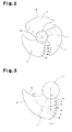
- a plurality of (three in the present embodiment) of recesses 21 to 23 are coaxially formed on the positive pressure surface at the trailing edge 2b of each blade 2.
- the recesses 21 to 23 each have an arcuate cross-section and a predetermined depth.
- protrusions 24, 25 having a predetermined height are each formed between adjacent ones of the recesses 21 to 23.
- the concave surfaces of the recesses 21 to 23 and the protrusions 24 and 25 effectively suppress radially outward air flow caused by centrifugal force, that is, outward air flow from the hub 1 to the outer tip 2c of the blade 2 (refer to the arrows in Fig. 4 ).
- the air blowing performance (efficiency and air blowing noise ) of the propeller fan is improved.
- protrusions 26 to 28 each having an arcuate cross-section are formed on the negative pressure surface at the trailing edge 2b of the blade 2.
- the protrusions 26 to 28 correspond to the recesses 21 to 23, which are formed on the positive pressure surface of the blade 2 and have an arcuate cross-section.
- the trailing edge 2b of the blade 2 is formed to have a wavy shape from the hub 1 to the outer tip 2c. Therefore, in the case of the thin blade 2 as illustrated, the recesses 21 to 23 having sufficient depths and the protrusions 24 and 25 having sufficient heights can be easily formed on the positive pressure surface of the blade 2.
- the recesses 21 to 23 and the protrusions 24 and 25 can be formed easily, and outward air flow from the hub 1 to the outer tip 2c of the blade 2 due to centrifugal force can be reliably reduced by the recesses 21 to 23 having sufficient depths and the protrusions 24 and 25 having sufficient heights.
- the recesses 21 to 23 are formed in a portion surrounded by the bellmouth 4 in a region closer to the trailing edge than the substantial center in the chord length that passes through the camber line of the trailing edge 2b of the blade 2.
- the sizes of the recesses 21 to 23 are gradually reduced at a center in the chord length of the blade 2, at which the recesses 21 to 23 merge into the same flat surface of the blade 2.
- the area in which the recesses 21 to 23 preferably ranges from 30% to 100% of the circumferential distance between the leading edge 2a and the trailing edge 2b (on the camber line at each position in the radial direction). In other words, the area preferably ranges from 30% to 100% of the chord length from its leading end (the range in which
- the above described recesses 21 to 23 are preferably formed in a part of a region from 0% to 85% of the distance R between the hub 1 and the outer tip 2c of the blade 2 (refer to Fig. 3 ), or over the entire region from 0% to 85% of the distance R between the hub 1 and the outer tip 2c of the blade 2.
- the shape of the recesses 21 to 23 is not limited to arcuate, but may be any type of concave surfaces including a curved surface of a long ellipse or a bent surface in which the curvature of the arcuate surface is changed as necessary.
- the shape of the recesses 21 to 23 may be changed in the following embodiments, also.
- the recesses 21 to 23 on the positive pressure surface and the protrusions 26 to 28 on the negative pressure surface of the blade 2 are formed without changing the contour (edge surface) of the trailing edge 2b from the hub 1 to the outer tip 2c.
- the shape of the trailing edge 2b of the blade 2 may be wavy with long waves and short waves.
- the trailing edge 2b may be saw-toothed.
- the widths and the numbers of the recesses 21 to 23 and the protrusions 24 and 25 may be changed, for example, like recesses 21a to 21f and the protrusions 24a to 24e shown in Fig. 6 . That is, the widths of the recesses 21a a to 21f and the protrusions 24a to 24e may be narrower than those in the first embodiment, and the numbers of the recesses 21a to 21f and the protrusions 24a to 24e may be greater than those in the first embodiment.
- the widths of the recesses 21a to 21f and the protrusions 24a to 24e may be gradually narrowed from the hub 1 toward the outer tip 2c of the blade 2.
- the bellmouth 4 is located about the blades 2.
- a predetermined space 5 exists between the inner circumferential surface of a cylindrical portion of the bellmouth 4 and the outer tip 2c of the blade 2
- leakage flow from the positive pressure surface to the negative pressure surface is generated in the space 5.
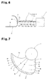
- the present embodiment provides a plurality of recessed surfaces and protruded surfaces are formed on the outer tip 2c of the blade as shown in Fig. 7 , in place of the configuration of the first embodiment.
- the recessed surfaces and protruded surfaces are formed both on the positive pressure surface and the negative pressure surface of the blade 2 at predetermined intervals, from a part of the outer tip 2c of the blade 2 near the leading edge 2a to a part near the trailing edge 2b (at least in a range including a point at which air flow starts leaking from the positive pressure surface to the negative pressure surface, the range sufficiently covering the subsequent parts). That is, multiple recesses and protrusions are formed with a plurality of inflection points.
- grooves A of the recesses of the recessed surfaces and crests B of the protrusions of the protruded surfaces are formed in a predetermined angle range at equal intervals, and extend from the axis of the hub 1 by a predetermined length.
- the grooves A and the crests B are formed to extend by a predetermined length in directions of a plurality of straight lines that radially extend from the axis of the hub 1 and are separated by predetermined equal angles.
- the grooves A of the recesses and the crests B of the protrusions are formed on the positive pressure surface and the negative pressure surface of the blade 2 by projecting or bending parts of the outer tip 2c toward the negative pressure surface with reference to the positive pressure surface of the blade 2 in a flat shape of the blade 2 having no recesses or protrusions (shown by broken lines).
- the alternate and consecutive grooves A of the recesses and crests B of the protrusions form a wavy portion having a constant thickness over the entire length from the leading edge 2a to the trailing edge 2b of the blade 2.
- the wavy outer tip 2c of the blade 2 breaks down the continuous leakage flow from the positive pressure surface to the negative pressure surface at the outer tip 2c of the blade 2 into discontinuous small flows shown in Fig. 9 . This reliably suppresses the development of a blade tip vortex having a common core caused by the leakage flow, which is observed in the conventional configuration.
- the configuration of the present embodiment provides a propeller fan with a higher blowing performance and blowing efficiency and a lower noise level.
- the shapes of the recessed surfaces and protruded surfaces may be each formed by a polygonal surface including a plurality of flat areas or by a curved surface.
- the recessed surfaces and the protruded surfaces are formed by curved surfaces, air flows smoothly along the curved areas. This allows the vortex to be smoothly divided.
- the recessed surfaces and the protruded surfaces may be formed in a part of or the entirety of the region of 80% to 100% of the distance R between the hub 1 and the outer tip 2c of the blade 2 (in a region where R 1 /R in Fig. 7 satisfies the inequality 0.8 ⁇ R1/R ⁇ 1.0).
- a continuous leakage flow flowing from the positive pressure surface to the negative pressure surface of the blade 2 can be divided into discontinuous flows without hindering the main flow of the blade 2. Accordingly, the development of blade tip vortex caused by leakage flow is further effectively reduced.
- a plurality of recesses 21a to 21c and protrusions 24a to 24c are formed as shown in Fig. 10 .
- the widths of the recesses 21a to 21c and protrusions 24a to 24c are different from those of the first embodiment. That is, the present embodiment is characterized in that the radial widths a to c of the recesses 21a to 21 are gradually reduced as the distance from the hub 1 increases toward the outer tip 2c (a > b > c).
- the recess 21a which is closest to the hub 1, has the greatest width, and the widths of the recesses 21b, 21c are reduced toward the outer tip 2c.
- the depths of the concave surface (bent surface) of the recesses 21a to 21c are constant.
- the recesses 21a to 21c and the protrusions 24a to 24c function in the same manner as the recesses 21 to 23 and the protrusions 26 to 28 of the first embodiment, so that the air blowing performance (efficiency and air blowing noise ) of the propeller fan is improved.
- the present embodiment is the same as the fifth embodiment except that the radial widths a to c of the recesses 21a to 21c and the protrusions 24a to 24c are gradually increased as the distance from the hub 1 increases toward the outer tip 2c as shown in Fig. 11 (a ⁇ b ⁇ c).
- the present embodiment therefore achieves the same operation as the fifth embodiment, and the air blowing performance (efficiency and air blowing noise ) of the propeller fan is improved.
- a plurality of recesses 21a to 21c and protrusions 24a to 24c are formed as in the first embodiment as shown in Fig 12 .
- the present embodiment is different from the first embodiment in that the depths h 1 to h 3 of the recesses 21a to 21c are gradually reduced as the distance from the hub 1 increases toward the outer tip 2c (h 1 > h 2 > h 3 ).
- the widths of the bent surface of the recesses 21a to 21c are constant.
- outward flow from the hub 1 toward the outer tip 2c the flow rate of which increases in accordance with an increase in the centrifugal force, can be reliably reduced by the recesses 21a to 21c having the depth h, which gradually decreases from the hub 1 toward the outer tip 2c, and the protrusions 24a to 24c having a height, which gradually increases accordingly.
- the present embodiment therefore achieves the same operation as the first embodiment, and the air blowing performance (efficiency and air blowing noise ) of the propeller fan is improved.
- the present embodiment is characterized and different from the seventh embodiment in that the depths of a plurality of recesses 21a to 21c are gradually increased as the distance from the hub 1 increases toward the outer tip 2c (h 1 > h 2 > h 3 ).
- outward flow from the hub 1 toward the outer tip 2c the flow rate of which increases in accordance with an increase in the centrifugal force, can be reliably reduced by the recesses 21a to 21c having the depth, which gradually increases from the hub 1 toward the outer tip 2c, and the protrusions 24a to 24c having a height, which gradually increases toward the outer tip 2c.
- the present embodiment therefore achieves the same operation as the seventh embodiment, and the air blowing performance (efficiency and air blowing noise) of the propeller fan is improved.
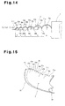
- the present embodiment is characterized and different from the first embodiment in that the radial widths a to f and the depth h 1 to h 6 of a plurality of recesses 21a to 21f both decrease as the distance from the hub 1 increases toward the outer tip 2c, for example, as shown in Figs. 14 and 15 (a > b > c > d > e > f and h 1 > h 2 > h 3 > h 4 > h 5 > h 6 ).
- the protrusions 26a to 26f are formed on the negative pressure surface in correspondence with the recesses 21a to 21e on the positive pressure surface.
- outward flow from the hub 1 toward the outer tip 2c can be reliably reduced by the recesses 21a to 21f and the protrusions 24a to 24e, the widths and depths (heights of the protrusions) of which gradually increase along the radial direction.
- the present embodiment therefore achieves the same operation as the first embodiment, and the air blowing performance (efficiency and air blowing noise ) of the propeller fan is improved.
- the radial widths a to e and the depth h 1 to h 5 of the recesses 21a to 21e may be reversed from those of the ninth embodiment.
- the widths a to e and the depths h 1 to h 5 of the recesses 21a to 21e may be formed to increase as the distance from the hub 1 increases toward the outer tip 2c (a ⁇ b ⁇ c ⁇ d ⁇ e and h 1 ⁇ h 2 ⁇ h 3 ⁇ h 4 ⁇ h 5 )
- outward flow from the hub 1 toward the outer tip 2c can be reliably reduced by the recesses 21a to 21e and the protrusions 24a to 24e, the widths and depths (heights) of which gradually increase along the radial direction, as in the above embodiments.
- the radial widths of the recesses 21a to 21c are different from those in the first embodiment. Specifically, the width c of the recess 21c close to the outer tip 2c is the greatest, and the width a of the recess 21a close to hub 1 is the next. The width b of the middle recess 21b is the smallest (c > a > b). In this manner, the present embodiment is characterized in that the radial widths of the recesses 21a to 21c are arranged irregularly. In this case, the depths of the recesses 21a to 21c may be constant or changed like the widths.
- This configuration reliably reduces outward flow from the hub 1 toward the outer tip 2c, the flow rate of which increases in accordance with an increase in the centrifugal force.
- recesses 21 to 23 and protrusions 24, 25 are formed on the positive pressure surface of the blade 2.
- the present embodiment is characterized in that the negative pressure surface of the blade 2 is formed as a flat surface as shown, for example, in Fig. 17 .
- the present embodiment therefore achieves the same operation as the first embodiment, and the air blowing performance (efficiency and air blowing noise ) of the propeller fan is improved.
- the present embodiment is suitable for a fan that has thick blades 2 and is hard to bend.
Landscapes
- Engineering & Computer Science (AREA)
- Mechanical Engineering (AREA)
- General Engineering & Computer Science (AREA)
- Structures Of Non-Positive Displacement Pumps (AREA)
Applications Claiming Priority (3)
| Application Number | Priority Date | Filing Date | Title |
|---|---|---|---|
| JP2008000452 | 2008-01-07 | ||
| JP2008322641A JP4400686B2 (ja) | 2008-01-07 | 2008-12-18 | プロペラファン |
| PCT/JP2009/050008 WO2009087985A1 (ja) | 2008-01-07 | 2009-01-05 | プロペラファン |
Publications (3)
| Publication Number | Publication Date |
|---|---|
| EP2230407A1 true EP2230407A1 (de) | 2010-09-22 |
| EP2230407A4 EP2230407A4 (de) | 2016-11-30 |
| EP2230407B1 EP2230407B1 (de) | 2018-08-01 |
Family
ID=40853099
Family Applications (1)
| Application Number | Title | Priority Date | Filing Date |
|---|---|---|---|
| EP09700760.3A Active EP2230407B1 (de) | 2008-01-07 | 2009-01-05 | Propellerlüfter |
Country Status (7)
| Country | Link |
|---|---|
| US (1) | US8721280B2 (de) |
| EP (1) | EP2230407B1 (de) |
| JP (1) | JP4400686B2 (de) |
| KR (1) | KR101228764B1 (de) |
| CN (1) | CN101910645A (de) |
| AU (1) | AU2009203471B2 (de) |
| WO (1) | WO2009087985A1 (de) |
Cited By (6)
| Publication number | Priority date | Publication date | Assignee | Title |
|---|---|---|---|---|
| EP2806221A3 (de) * | 2013-05-20 | 2014-12-17 | Samsung Electronics Co., Ltd | Propellergebläse und Klimaanlage damit |
| EP2792886A3 (de) * | 2013-04-19 | 2015-06-17 | LG Electronics Inc. | Turbolüfter |
| EP2902639A4 (de) * | 2012-09-28 | 2016-05-25 | Daikin Ind Ltd | Propellerlüfter und klimaanlage damit |
| WO2017036470A1 (de) * | 2015-08-31 | 2017-03-09 | Ziehl-Abegg Se | Lüfterrad, lüfter und system mit mindestens einem lüfter |
| EP2711558A3 (de) * | 2012-09-24 | 2017-12-13 | Samsung Electronics Co., Ltd | Propellerlüfter |
| EP3348842A4 (de) * | 2015-09-08 | 2018-09-12 | Mitsubishi Electric Corporation | Propellerlüfter, propellerlüftervorrichtung und ausseneinheit für eine klimaanlage |
Families Citing this family (34)
| Publication number | Priority date | Publication date | Assignee | Title |
|---|---|---|---|---|
| JP5366532B2 (ja) * | 2008-12-24 | 2013-12-11 | 東芝キヤリア株式会社 | 軸流ファンおよび空気調和機の室外機 |
| JP5263198B2 (ja) * | 2010-02-26 | 2013-08-14 | パナソニック株式会社 | 羽根車と送風機及びそれを用いた空気調和機 |
| JP5425678B2 (ja) * | 2010-03-24 | 2014-02-26 | 三洋電機株式会社 | 軸流ファン |
| TWI464328B (zh) * | 2010-11-05 | 2014-12-11 | Delta Electronics Inc | 風扇結構 |
| DE102011006275A1 (de) * | 2011-03-28 | 2012-10-04 | Rolls-Royce Deutschland Ltd & Co Kg | Stator einer Axialverdichterstufe einer Turbomaschine |
| DE102011006273A1 (de) | 2011-03-28 | 2012-10-04 | Rolls-Royce Deutschland Ltd & Co Kg | Rotor einer Axialverdichterstufe einer Turbomaschine |
| DE102011007767A1 (de) | 2011-04-20 | 2012-10-25 | Rolls-Royce Deutschland Ltd & Co Kg | Strömungsmaschine |
| KR20130039481A (ko) * | 2011-10-12 | 2013-04-22 | 엘지전자 주식회사 | 축류팬 및 공기 조화기 |
| MY166098A (en) | 2012-04-10 | 2018-05-24 | Sharp Kk | Propeller fan, fluid feeder, and molding die |
| CN104314868B (zh) | 2012-04-10 | 2017-07-14 | 夏普株式会社 | 螺旋桨式风扇、流体输送装置、电风扇以及成形用模具 |
| KR101920085B1 (ko) * | 2012-09-12 | 2018-11-19 | 엘지전자 주식회사 | 팬 |
| US20140147282A1 (en) * | 2012-11-23 | 2014-05-29 | Cooler Master Co., Ltd. | Fan structure |
| WO2014102970A1 (ja) * | 2012-12-27 | 2014-07-03 | 三菱電機株式会社 | プロペラファン、送風装置、室外機 |
| JP5611379B2 (ja) * | 2013-01-23 | 2014-10-22 | 株式会社豊田自動織機 | ターボチャージャ用インペラ、ターボチャージャ用インペラの製造方法、ターボチャージャ、及びターボユニット |
| JP1530002S (de) * | 2014-08-11 | 2015-08-03 | ||
| JP6377172B2 (ja) * | 2014-11-04 | 2018-08-22 | 三菱電機株式会社 | プロペラファン、プロペラファン装置および空気調和装置用室外機 |
| CN107407290B (zh) | 2015-04-08 | 2019-07-26 | 雷顿股份公司 | 风扇叶片及相关方法 |
| WO2016181463A1 (ja) * | 2015-05-11 | 2016-11-17 | 三菱電機株式会社 | 軸流送風機 |
| CN104986313A (zh) * | 2015-08-05 | 2015-10-21 | 李清林 | 多凹型面螺旋桨 |
| DE112016006555B4 (de) * | 2016-03-07 | 2023-10-12 | Mitsubishi Electric Corporation | Axialventilator und Ausseneinheit |
| WO2018127953A1 (ja) * | 2017-01-05 | 2018-07-12 | 三菱電機株式会社 | プロペラファン及び空気調和装置の室外機 |
| CN106640748B (zh) * | 2017-01-06 | 2022-12-02 | 珠海格力电器股份有限公司 | 叶片、叶轮及风机 |
| EP3591236B1 (de) | 2017-02-28 | 2021-03-24 | Mitsubishi Electric Corporation | Propellerlüfter, gebläse und klimaanlage |
| JP6644026B2 (ja) * | 2017-06-02 | 2020-02-12 | シャープ株式会社 | プロペラファンおよびこれを備えた流体送り装置ならびにプロペラファンの成形用金型 |
| CN206968981U (zh) * | 2017-06-26 | 2018-02-06 | 深圳市大疆创新科技有限公司 | 螺旋桨、动力装置及飞行器 |
| USD901669S1 (en) | 2017-09-29 | 2020-11-10 | Carrier Corporation | Contoured fan blade |
| JP6685474B2 (ja) * | 2018-02-07 | 2020-04-22 | 広東美的制冷設備有限公司Gd Midea Air−Conditioning Equipment Co.,Ltd. | 軸流ファン及びエアコン |
| JP6696525B2 (ja) | 2018-03-22 | 2020-05-20 | 株式会社富士通ゼネラル | プロペラファン |
| CN109488637A (zh) * | 2018-11-13 | 2019-03-19 | 华帝股份有限公司 | 一种风轮、风机和吸油烟机 |
| US11680580B2 (en) * | 2018-11-22 | 2023-06-20 | Gd Midea Air-Conditioning Equipment Co., Ltd. | Axial-flow impeller and air-conditioner having the same |
| DE202019100367U1 (de) * | 2019-01-23 | 2020-04-24 | Brose Fahrzeugteile SE & Co. Kommanditgesellschaft, Würzburg | Lüfterrad eines Kraftfahrzeugs |
| US11187083B2 (en) | 2019-05-07 | 2021-11-30 | Carrier Corporation | HVAC fan |
| USD980965S1 (en) | 2019-05-07 | 2023-03-14 | Carrier Corporation | Leading edge of a fan blade |
| JP2023015577A (ja) | 2021-07-20 | 2023-02-01 | 山洋電気株式会社 | 軸流ファン |
Family Cites Families (26)
| Publication number | Priority date | Publication date | Assignee | Title |
|---|---|---|---|---|
| US2899128A (en) * | 1959-08-11 | Vaghi | ||
| US1366635A (en) * | 1919-03-31 | 1921-01-25 | Edward P Conway | Propeller |
| US2013473A (en) * | 1932-09-24 | 1935-09-03 | Gauger | Fluid propeller |
| US2238749A (en) * | 1939-01-30 | 1941-04-15 | Clarence B Swift | Fan blade |
| US2265788A (en) * | 1940-11-02 | 1941-12-09 | Sr Frank Wolf | Propeller |
| JPS6040880Y2 (ja) * | 1979-12-08 | 1985-12-10 | 日産ディーゼル工業株式会社 | 内燃機関のク−リングフアン |
| JPS56143594U (de) | 1980-03-31 | 1981-10-29 | ||
| DE3325663C2 (de) * | 1983-07-15 | 1985-08-22 | MTU Motoren- und Turbinen-Union München GmbH, 8000 München | Axial durchströmtes Schaufelgitter einer mit Gas oder Dampf betriebenen Turbine |
| JP2613272B2 (ja) * | 1988-08-29 | 1997-05-21 | 株式会社日立製作所 | 軸流ファン |
| DE9013099U1 (de) | 1990-09-14 | 1991-11-07 | Moser, Josef, 8058 Pretzen, De | |
| JPH0544695A (ja) | 1991-08-08 | 1993-02-23 | Matsushita Refrig Co Ltd | 送風機 |
| JPH08177792A (ja) | 1994-10-25 | 1996-07-12 | Matsushita Seiko Co Ltd | 軸流ファン |
| JPH08121386A (ja) | 1994-10-31 | 1996-05-14 | Fuji Kogyo Kk | プロペラファン |
| JP2000110785A (ja) | 1998-10-05 | 2000-04-18 | Calsonic Corp | 軸流ファン |
| US6280144B1 (en) * | 1998-11-10 | 2001-08-28 | Charles S. Powers | Propellers and impellers with stress-relieving recesses |
| AU2002221045B2 (en) | 2000-12-28 | 2005-10-06 | Daikin Industries, Ltd. | Blower, and outdoor unit for air conditioner |
| JP3978083B2 (ja) | 2001-06-12 | 2007-09-19 | 漢拏空調株式会社 | 軸流ファン |
| JP2003227302A (ja) * | 2002-02-04 | 2003-08-15 | Ishikawajima Harima Heavy Ind Co Ltd | 伴流混合促進翼 |
| JP3979388B2 (ja) | 2002-02-28 | 2007-09-19 | ダイキン工業株式会社 | 送風機 |
| JP4467952B2 (ja) | 2003-11-10 | 2010-05-26 | 東芝キヤリア株式会社 | プロペラファン、これを用いた空気調和機用室外ユニット |
| DE502004010281D1 (de) * | 2004-06-02 | 2009-12-03 | Rolls Royce Deutschland | Verdichterschaufel, insbesondere für den Fan von Flugzeugtriebwerken |
| CN2864168Y (zh) | 2005-12-26 | 2007-01-31 | 海信集团有限公司 | 轴流风扇 |
| JP4973249B2 (ja) | 2006-03-31 | 2012-07-11 | ダイキン工業株式会社 | 多翼ファン |
| US8083487B2 (en) * | 2007-07-09 | 2011-12-27 | General Electric Company | Rotary airfoils and method for fabricating same |
| JP5125518B2 (ja) * | 2007-07-11 | 2013-01-23 | ダイキン工業株式会社 | プロペラファン |
| CA2763898A1 (en) * | 2009-06-03 | 2010-12-09 | Flodesign Wind Turbine Corp. | Wind turbine blades with mixer lobes |
-
2008
- 2008-12-18 JP JP2008322641A patent/JP4400686B2/ja active Active
-
2009
- 2009-01-05 US US12/746,742 patent/US8721280B2/en active Active
- 2009-01-05 WO PCT/JP2009/050008 patent/WO2009087985A1/ja active Application Filing
- 2009-01-05 EP EP09700760.3A patent/EP2230407B1/de active Active
- 2009-01-05 KR KR1020107014670A patent/KR101228764B1/ko active IP Right Grant
- 2009-01-05 CN CN200980101462XA patent/CN101910645A/zh active Pending
- 2009-01-05 AU AU2009203471A patent/AU2009203471B2/en active Active
Non-Patent Citations (1)
| Title |
|---|
| See references of WO2009087985A1 * |
Cited By (8)
| Publication number | Priority date | Publication date | Assignee | Title |
|---|---|---|---|---|
| EP2711558A3 (de) * | 2012-09-24 | 2017-12-13 | Samsung Electronics Co., Ltd | Propellerlüfter |
| EP2902639A4 (de) * | 2012-09-28 | 2016-05-25 | Daikin Ind Ltd | Propellerlüfter und klimaanlage damit |
| EP2792886A3 (de) * | 2013-04-19 | 2015-06-17 | LG Electronics Inc. | Turbolüfter |
| EP2806221A3 (de) * | 2013-05-20 | 2014-12-17 | Samsung Electronics Co., Ltd | Propellergebläse und Klimaanlage damit |
| WO2017036470A1 (de) * | 2015-08-31 | 2017-03-09 | Ziehl-Abegg Se | Lüfterrad, lüfter und system mit mindestens einem lüfter |
| US11371529B2 (en) | 2015-08-31 | 2022-06-28 | Ziehl-Abegg Se | Fan wheel, fan, and system having at least one fan |
| EP3348842A4 (de) * | 2015-09-08 | 2018-09-12 | Mitsubishi Electric Corporation | Propellerlüfter, propellerlüftervorrichtung und ausseneinheit für eine klimaanlage |
| US10634161B2 (en) | 2015-09-08 | 2020-04-28 | Mitsubishi Electric Corporation | Propeller fan, propeller fan device, and air conditioner outdoor unit |
Also Published As
| Publication number | Publication date |
|---|---|
| AU2009203471A1 (en) | 2009-07-16 |
| US20100266428A1 (en) | 2010-10-21 |
| AU2009203471B2 (en) | 2011-08-04 |
| JP4400686B2 (ja) | 2010-01-20 |
| JP2009185803A (ja) | 2009-08-20 |
| KR20100096219A (ko) | 2010-09-01 |
| EP2230407B1 (de) | 2018-08-01 |
| EP2230407A4 (de) | 2016-11-30 |
| US8721280B2 (en) | 2014-05-13 |
| KR101228764B1 (ko) | 2013-01-31 |
| CN101910645A (zh) | 2010-12-08 |
| WO2009087985A1 (ja) | 2009-07-16 |
Similar Documents
| Publication | Publication Date | Title |
|---|---|---|
| US8721280B2 (en) | Propeller fan | |
| JP5125518B2 (ja) | プロペラファン | |
| EP2902639B1 (de) | Propellerlüfter und klimaanlage damit | |
| JP5097201B2 (ja) | 軸流ファン組立体 | |
| JP5737666B2 (ja) | 遠心式送風機または斜流送風機に用いられるインペラ | |
| US7244099B2 (en) | Multi-vane centrifugal fan | |
| EP1916422A2 (de) | Zentrifugalgebläse | |
| US20040136830A1 (en) | Fan | |
| EP2275689A1 (de) | Zentrifugalgebläse | |
| US20100189557A1 (en) | Impeller and fan | |
| US9206817B2 (en) | Centrifugal blower | |
| JP6914371B2 (ja) | 軸流送風機 | |
| WO2012039092A1 (ja) | 軸流送風機 | |
| US8926278B2 (en) | Fan and fan frame thereof | |
| JP4014887B2 (ja) | 遠心ファンおよびその遠心ファンを備えた加熱調理器 | |
| CN111577655A (zh) | 叶片及使用其的轴流叶轮 | |
| US7771169B2 (en) | Centrifugal multiblade fan | |
| WO2008082428A1 (en) | Reduced tip clearance losses in axial flow fans | |
| JP3902193B2 (ja) | 多翼遠心送風機 | |
| RU83554U1 (ru) | Рабочее колесо радиального вентилятора с постоянным сечением выбросного канала | |
| JPH11182482A (ja) | 高比速度の斜流ポンプ | |
| CN116648561A (zh) | 送风机 | |
| JP2012052430A (ja) | 遠心送風機 |
Legal Events
| Date | Code | Title | Description |
|---|---|---|---|
| PUAI | Public reference made under article 153(3) epc to a published international application that has entered the european phase |
Free format text: ORIGINAL CODE: 0009012 |
|
| 17P | Request for examination filed |
Effective date: 20100621 |
|
| AK | Designated contracting states |
Kind code of ref document: A1 Designated state(s): AT BE BG CH CY CZ DE DK EE ES FI FR GB GR HR HU IE IS IT LI LT LU LV MC MK MT NL NO PL PT RO SE SI SK TR |
|
| AX | Request for extension of the european patent |
Extension state: AL BA RS |
|
| DAX | Request for extension of the european patent (deleted) | ||
| REG | Reference to a national code |
Ref country code: DE Ref legal event code: R079 Ref document number: 602009053555 Country of ref document: DE Free format text: PREVIOUS MAIN CLASS: F04D0029380000 Ipc: F04D0029160000 |
|
| RA4 | Supplementary search report drawn up and despatched (corrected) |
Effective date: 20161102 |
|
| RIC1 | Information provided on ipc code assigned before grant |
Ipc: F04D 29/16 20060101AFI20161026BHEP Ipc: F04D 29/38 20060101ALI20161026BHEP |
|
| GRAP | Despatch of communication of intention to grant a patent |
Free format text: ORIGINAL CODE: EPIDOSNIGR1 |
|
| STAA | Information on the status of an ep patent application or granted ep patent |
Free format text: STATUS: GRANT OF PATENT IS INTENDED |
|
| INTG | Intention to grant announced |
Effective date: 20180307 |
|
| GRAJ | Information related to disapproval of communication of intention to grant by the applicant or resumption of examination proceedings by the epo deleted |
Free format text: ORIGINAL CODE: EPIDOSDIGR1 |
|
| STAA | Information on the status of an ep patent application or granted ep patent |
Free format text: STATUS: REQUEST FOR EXAMINATION WAS MADE |
|
| GRAR | Information related to intention to grant a patent recorded |
Free format text: ORIGINAL CODE: EPIDOSNIGR71 |
|
| GRAS | Grant fee paid |
Free format text: ORIGINAL CODE: EPIDOSNIGR3 |
|
| STAA | Information on the status of an ep patent application or granted ep patent |
Free format text: STATUS: GRANT OF PATENT IS INTENDED |
|
| GRAA | (expected) grant |
Free format text: ORIGINAL CODE: 0009210 |
|
| STAA | Information on the status of an ep patent application or granted ep patent |
Free format text: STATUS: THE PATENT HAS BEEN GRANTED |
|
| INTC | Intention to grant announced (deleted) | ||
| AK | Designated contracting states |
Kind code of ref document: B1 Designated state(s): AT BE BG CH CY CZ DE DK EE ES FI FR GB GR HR HU IE IS IT LI LT LU LV MC MK MT NL NO PL PT RO SE SI SK TR |
|
| INTG | Intention to grant announced |
Effective date: 20180625 |
|
| REG | Reference to a national code |
Ref country code: GB Ref legal event code: FG4D |
|
| REG | Reference to a national code |
Ref country code: CH Ref legal event code: EP Ref country code: AT Ref legal event code: REF Ref document number: 1024639 Country of ref document: AT Kind code of ref document: T Effective date: 20180815 |
|
| REG | Reference to a national code |
Ref country code: IE Ref legal event code: FG4D |
|
| REG | Reference to a national code |
Ref country code: DE Ref legal event code: R096 Ref document number: 602009053555 Country of ref document: DE |
|
| REG | Reference to a national code |
Ref country code: NL Ref legal event code: MP Effective date: 20180801 |
|
| REG | Reference to a national code |
Ref country code: LT Ref legal event code: MG4D |
|
| REG | Reference to a national code |
Ref country code: AT Ref legal event code: MK05 Ref document number: 1024639 Country of ref document: AT Kind code of ref document: T Effective date: 20180801 |
|
| PG25 | Lapsed in a contracting state [announced via postgrant information from national office to epo] |
Ref country code: LT Free format text: LAPSE BECAUSE OF FAILURE TO SUBMIT A TRANSLATION OF THE DESCRIPTION OR TO PAY THE FEE WITHIN THE PRESCRIBED TIME-LIMIT Effective date: 20180801 Ref country code: PL Free format text: LAPSE BECAUSE OF FAILURE TO SUBMIT A TRANSLATION OF THE DESCRIPTION OR TO PAY THE FEE WITHIN THE PRESCRIBED TIME-LIMIT Effective date: 20180801 Ref country code: AT Free format text: LAPSE BECAUSE OF FAILURE TO SUBMIT A TRANSLATION OF THE DESCRIPTION OR TO PAY THE FEE WITHIN THE PRESCRIBED TIME-LIMIT Effective date: 20180801 Ref country code: NL Free format text: LAPSE BECAUSE OF FAILURE TO SUBMIT A TRANSLATION OF THE DESCRIPTION OR TO PAY THE FEE WITHIN THE PRESCRIBED TIME-LIMIT Effective date: 20180801 Ref country code: BG Free format text: LAPSE BECAUSE OF FAILURE TO SUBMIT A TRANSLATION OF THE DESCRIPTION OR TO PAY THE FEE WITHIN THE PRESCRIBED TIME-LIMIT Effective date: 20181101 Ref country code: SE Free format text: LAPSE BECAUSE OF FAILURE TO SUBMIT A TRANSLATION OF THE DESCRIPTION OR TO PAY THE FEE WITHIN THE PRESCRIBED TIME-LIMIT Effective date: 20180801 Ref country code: FI Free format text: LAPSE BECAUSE OF FAILURE TO SUBMIT A TRANSLATION OF THE DESCRIPTION OR TO PAY THE FEE WITHIN THE PRESCRIBED TIME-LIMIT Effective date: 20180801 Ref country code: GR Free format text: LAPSE BECAUSE OF FAILURE TO SUBMIT A TRANSLATION OF THE DESCRIPTION OR TO PAY THE FEE WITHIN THE PRESCRIBED TIME-LIMIT Effective date: 20181102 Ref country code: NO Free format text: LAPSE BECAUSE OF FAILURE TO SUBMIT A TRANSLATION OF THE DESCRIPTION OR TO PAY THE FEE WITHIN THE PRESCRIBED TIME-LIMIT Effective date: 20181101 Ref country code: IS Free format text: LAPSE BECAUSE OF FAILURE TO SUBMIT A TRANSLATION OF THE DESCRIPTION OR TO PAY THE FEE WITHIN THE PRESCRIBED TIME-LIMIT Effective date: 20181201 |
|
| PG25 | Lapsed in a contracting state [announced via postgrant information from national office to epo] |
Ref country code: ES Free format text: LAPSE BECAUSE OF FAILURE TO SUBMIT A TRANSLATION OF THE DESCRIPTION OR TO PAY THE FEE WITHIN THE PRESCRIBED TIME-LIMIT Effective date: 20180801 Ref country code: LV Free format text: LAPSE BECAUSE OF FAILURE TO SUBMIT A TRANSLATION OF THE DESCRIPTION OR TO PAY THE FEE WITHIN THE PRESCRIBED TIME-LIMIT Effective date: 20180801 Ref country code: HR Free format text: LAPSE BECAUSE OF FAILURE TO SUBMIT A TRANSLATION OF THE DESCRIPTION OR TO PAY THE FEE WITHIN THE PRESCRIBED TIME-LIMIT Effective date: 20180801 |
|
| PG25 | Lapsed in a contracting state [announced via postgrant information from national office to epo] |
Ref country code: EE Free format text: LAPSE BECAUSE OF FAILURE TO SUBMIT A TRANSLATION OF THE DESCRIPTION OR TO PAY THE FEE WITHIN THE PRESCRIBED TIME-LIMIT Effective date: 20180801 Ref country code: IT Free format text: LAPSE BECAUSE OF FAILURE TO SUBMIT A TRANSLATION OF THE DESCRIPTION OR TO PAY THE FEE WITHIN THE PRESCRIBED TIME-LIMIT Effective date: 20180801 Ref country code: RO Free format text: LAPSE BECAUSE OF FAILURE TO SUBMIT A TRANSLATION OF THE DESCRIPTION OR TO PAY THE FEE WITHIN THE PRESCRIBED TIME-LIMIT Effective date: 20180801 Ref country code: CZ Free format text: LAPSE BECAUSE OF FAILURE TO SUBMIT A TRANSLATION OF THE DESCRIPTION OR TO PAY THE FEE WITHIN THE PRESCRIBED TIME-LIMIT Effective date: 20180801 |
|
| REG | Reference to a national code |
Ref country code: DE Ref legal event code: R097 Ref document number: 602009053555 Country of ref document: DE |
|
| PG25 | Lapsed in a contracting state [announced via postgrant information from national office to epo] |
Ref country code: SK Free format text: LAPSE BECAUSE OF FAILURE TO SUBMIT A TRANSLATION OF THE DESCRIPTION OR TO PAY THE FEE WITHIN THE PRESCRIBED TIME-LIMIT Effective date: 20180801 Ref country code: DK Free format text: LAPSE BECAUSE OF FAILURE TO SUBMIT A TRANSLATION OF THE DESCRIPTION OR TO PAY THE FEE WITHIN THE PRESCRIBED TIME-LIMIT Effective date: 20180801 |
|
| PLBE | No opposition filed within time limit |
Free format text: ORIGINAL CODE: 0009261 |
|
| STAA | Information on the status of an ep patent application or granted ep patent |
Free format text: STATUS: NO OPPOSITION FILED WITHIN TIME LIMIT |
|
| 26N | No opposition filed |
Effective date: 20190503 |
|
| PG25 | Lapsed in a contracting state [announced via postgrant information from national office to epo] |
Ref country code: SI Free format text: LAPSE BECAUSE OF FAILURE TO SUBMIT A TRANSLATION OF THE DESCRIPTION OR TO PAY THE FEE WITHIN THE PRESCRIBED TIME-LIMIT Effective date: 20180801 Ref country code: MC Free format text: LAPSE BECAUSE OF FAILURE TO SUBMIT A TRANSLATION OF THE DESCRIPTION OR TO PAY THE FEE WITHIN THE PRESCRIBED TIME-LIMIT Effective date: 20180801 |
|
| REG | Reference to a national code |
Ref country code: CH Ref legal event code: PL |
|
| PG25 | Lapsed in a contracting state [announced via postgrant information from national office to epo] |
Ref country code: LU Free format text: LAPSE BECAUSE OF NON-PAYMENT OF DUE FEES Effective date: 20190105 |
|
| REG | Reference to a national code |
Ref country code: BE Ref legal event code: MM Effective date: 20190131 |
|
| REG | Reference to a national code |
Ref country code: IE Ref legal event code: MM4A |
|
| PG25 | Lapsed in a contracting state [announced via postgrant information from national office to epo] |
Ref country code: BE Free format text: LAPSE BECAUSE OF NON-PAYMENT OF DUE FEES Effective date: 20190131 |
|
| PG25 | Lapsed in a contracting state [announced via postgrant information from national office to epo] |
Ref country code: LI Free format text: LAPSE BECAUSE OF NON-PAYMENT OF DUE FEES Effective date: 20190131 Ref country code: CH Free format text: LAPSE BECAUSE OF NON-PAYMENT OF DUE FEES Effective date: 20190131 |
|
| PG25 | Lapsed in a contracting state [announced via postgrant information from national office to epo] |
Ref country code: IE Free format text: LAPSE BECAUSE OF NON-PAYMENT OF DUE FEES Effective date: 20190105 |
|
| PG25 | Lapsed in a contracting state [announced via postgrant information from national office to epo] |
Ref country code: TR Free format text: LAPSE BECAUSE OF FAILURE TO SUBMIT A TRANSLATION OF THE DESCRIPTION OR TO PAY THE FEE WITHIN THE PRESCRIBED TIME-LIMIT Effective date: 20180801 |
|
| PG25 | Lapsed in a contracting state [announced via postgrant information from national office to epo] |
Ref country code: MT Free format text: LAPSE BECAUSE OF NON-PAYMENT OF DUE FEES Effective date: 20190105 Ref country code: PT Free format text: LAPSE BECAUSE OF FAILURE TO SUBMIT A TRANSLATION OF THE DESCRIPTION OR TO PAY THE FEE WITHIN THE PRESCRIBED TIME-LIMIT Effective date: 20181201 |
|
| PG25 | Lapsed in a contracting state [announced via postgrant information from national office to epo] |
Ref country code: CY Free format text: LAPSE BECAUSE OF FAILURE TO SUBMIT A TRANSLATION OF THE DESCRIPTION OR TO PAY THE FEE WITHIN THE PRESCRIBED TIME-LIMIT Effective date: 20180801 |
|
| PG25 | Lapsed in a contracting state [announced via postgrant information from national office to epo] |
Ref country code: HU Free format text: LAPSE BECAUSE OF FAILURE TO SUBMIT A TRANSLATION OF THE DESCRIPTION OR TO PAY THE FEE WITHIN THE PRESCRIBED TIME-LIMIT; INVALID AB INITIO Effective date: 20090105 |
|
| PG25 | Lapsed in a contracting state [announced via postgrant information from national office to epo] |
Ref country code: MK Free format text: LAPSE BECAUSE OF FAILURE TO SUBMIT A TRANSLATION OF THE DESCRIPTION OR TO PAY THE FEE WITHIN THE PRESCRIBED TIME-LIMIT Effective date: 20180801 |
|
| P01 | Opt-out of the competence of the unified patent court (upc) registered |
Effective date: 20230525 |
|
| PGFP | Annual fee paid to national office [announced via postgrant information from national office to epo] |
Ref country code: GB Payment date: 20231130 Year of fee payment: 16 |
|
| PGFP | Annual fee paid to national office [announced via postgrant information from national office to epo] |
Ref country code: FR Payment date: 20231212 Year of fee payment: 16 |
|
| PGFP | Annual fee paid to national office [announced via postgrant information from national office to epo] |
Ref country code: DE Payment date: 20231128 Year of fee payment: 16 |