EP4067658B1 - Vakuumpumpengerät - Google Patents
Vakuumpumpengerät Download PDFInfo
- Publication number
- EP4067658B1 EP4067658B1 EP22164110.3A EP22164110A EP4067658B1 EP 4067658 B1 EP4067658 B1 EP 4067658B1 EP 22164110 A EP22164110 A EP 22164110A EP 4067658 B1 EP4067658 B1 EP 4067658B1
- Authority
- EP
- European Patent Office
- Prior art keywords
- wall portion
- vacuum pump
- heater
- side cover
- pump apparatus
- Prior art date
- Legal status (The legal status is an assumption and is not a legal conclusion. Google has not performed a legal analysis and makes no representation as to the accuracy of the status listed.)
- Active
Links
Images


Classifications
-
- F—MECHANICAL ENGINEERING; LIGHTING; HEATING; WEAPONS; BLASTING
- F04—POSITIVE - DISPLACEMENT MACHINES FOR LIQUIDS; PUMPS FOR LIQUIDS OR ELASTIC FLUIDS
- F04C—ROTARY-PISTON, OR OSCILLATING-PISTON, POSITIVE-DISPLACEMENT MACHINES FOR LIQUIDS; ROTARY-PISTON, OR OSCILLATING-PISTON, POSITIVE-DISPLACEMENT PUMPS
- F04C18/00—Rotary-piston pumps specially adapted for elastic fluids
- F04C18/08—Rotary-piston pumps specially adapted for elastic fluids of intermeshing-engagement type, i.e. with engagement of co-operating members similar to that of toothed gearing
- F04C18/082—Details specially related to intermeshing engagement type pumps
- F04C18/084—Toothed wheels
-
- F—MECHANICAL ENGINEERING; LIGHTING; HEATING; WEAPONS; BLASTING
- F04—POSITIVE - DISPLACEMENT MACHINES FOR LIQUIDS; PUMPS FOR LIQUIDS OR ELASTIC FLUIDS
- F04C—ROTARY-PISTON, OR OSCILLATING-PISTON, POSITIVE-DISPLACEMENT MACHINES FOR LIQUIDS; ROTARY-PISTON, OR OSCILLATING-PISTON, POSITIVE-DISPLACEMENT PUMPS
- F04C18/00—Rotary-piston pumps specially adapted for elastic fluids
- F04C18/08—Rotary-piston pumps specially adapted for elastic fluids of intermeshing-engagement type, i.e. with engagement of co-operating members similar to that of toothed gearing
- F04C18/12—Rotary-piston pumps specially adapted for elastic fluids of intermeshing-engagement type, i.e. with engagement of co-operating members similar to that of toothed gearing of other than internal-axis type
- F04C18/126—Rotary-piston pumps specially adapted for elastic fluids of intermeshing-engagement type, i.e. with engagement of co-operating members similar to that of toothed gearing of other than internal-axis type with radially from the rotor body extending elements, not necessarily co-operating with corresponding recesses in the other rotor, e.g. lobes, Roots type
-
- F—MECHANICAL ENGINEERING; LIGHTING; HEATING; WEAPONS; BLASTING
- F04—POSITIVE - DISPLACEMENT MACHINES FOR LIQUIDS; PUMPS FOR LIQUIDS OR ELASTIC FLUIDS
- F04C—ROTARY-PISTON, OR OSCILLATING-PISTON, POSITIVE-DISPLACEMENT MACHINES FOR LIQUIDS; ROTARY-PISTON, OR OSCILLATING-PISTON, POSITIVE-DISPLACEMENT PUMPS
- F04C18/00—Rotary-piston pumps specially adapted for elastic fluids
- F04C18/08—Rotary-piston pumps specially adapted for elastic fluids of intermeshing-engagement type, i.e. with engagement of co-operating members similar to that of toothed gearing
- F04C18/12—Rotary-piston pumps specially adapted for elastic fluids of intermeshing-engagement type, i.e. with engagement of co-operating members similar to that of toothed gearing of other than internal-axis type
- F04C18/14—Rotary-piston pumps specially adapted for elastic fluids of intermeshing-engagement type, i.e. with engagement of co-operating members similar to that of toothed gearing of other than internal-axis type with toothed rotary pistons
- F04C18/16—Rotary-piston pumps specially adapted for elastic fluids of intermeshing-engagement type, i.e. with engagement of co-operating members similar to that of toothed gearing of other than internal-axis type with toothed rotary pistons with helical teeth, e.g. chevron-shaped, screw type
-
- F—MECHANICAL ENGINEERING; LIGHTING; HEATING; WEAPONS; BLASTING
- F04—POSITIVE - DISPLACEMENT MACHINES FOR LIQUIDS; PUMPS FOR LIQUIDS OR ELASTIC FLUIDS
- F04C—ROTARY-PISTON, OR OSCILLATING-PISTON, POSITIVE-DISPLACEMENT MACHINES FOR LIQUIDS; ROTARY-PISTON, OR OSCILLATING-PISTON, POSITIVE-DISPLACEMENT PUMPS
- F04C23/00—Combinations of two or more pumps, each being of rotary-piston or oscillating-piston type, specially adapted for elastic fluids; Pumping installations specially adapted for elastic fluids; Multi-stage pumps specially adapted for elastic fluids
- F04C23/02—Pumps characterised by combination with, or adaptation to, specific driving engines or motors
-
- F—MECHANICAL ENGINEERING; LIGHTING; HEATING; WEAPONS; BLASTING
- F04—POSITIVE - DISPLACEMENT MACHINES FOR LIQUIDS; PUMPS FOR LIQUIDS OR ELASTIC FLUIDS
- F04C—ROTARY-PISTON, OR OSCILLATING-PISTON, POSITIVE-DISPLACEMENT MACHINES FOR LIQUIDS; ROTARY-PISTON, OR OSCILLATING-PISTON, POSITIVE-DISPLACEMENT PUMPS
- F04C25/00—Adaptations of pumps for special use of pumps for elastic fluids
- F04C25/02—Adaptations of pumps for special use of pumps for elastic fluids for producing high vacuum
-
- F—MECHANICAL ENGINEERING; LIGHTING; HEATING; WEAPONS; BLASTING
- F04—POSITIVE - DISPLACEMENT MACHINES FOR LIQUIDS; PUMPS FOR LIQUIDS OR ELASTIC FLUIDS
- F04C—ROTARY-PISTON, OR OSCILLATING-PISTON, POSITIVE-DISPLACEMENT MACHINES FOR LIQUIDS; ROTARY-PISTON, OR OSCILLATING-PISTON, POSITIVE-DISPLACEMENT PUMPS
- F04C29/00—Component parts, details or accessories of pumps or pumping installations, not provided for in groups F04C18/00 - F04C28/00
- F04C29/0042—Driving elements, brakes, couplings, transmissions specially adapted for pumps
- F04C29/0085—Prime movers
-
- F—MECHANICAL ENGINEERING; LIGHTING; HEATING; WEAPONS; BLASTING
- F04—POSITIVE - DISPLACEMENT MACHINES FOR LIQUIDS; PUMPS FOR LIQUIDS OR ELASTIC FLUIDS
- F04C—ROTARY-PISTON, OR OSCILLATING-PISTON, POSITIVE-DISPLACEMENT MACHINES FOR LIQUIDS; ROTARY-PISTON, OR OSCILLATING-PISTON, POSITIVE-DISPLACEMENT PUMPS
- F04C29/00—Component parts, details or accessories of pumps or pumping installations, not provided for in groups F04C18/00 - F04C28/00
- F04C29/04—Heating; Cooling; Heat insulation
-
- F—MECHANICAL ENGINEERING; LIGHTING; HEATING; WEAPONS; BLASTING
- F04—POSITIVE - DISPLACEMENT MACHINES FOR LIQUIDS; PUMPS FOR LIQUIDS OR ELASTIC FLUIDS
- F04C—ROTARY-PISTON, OR OSCILLATING-PISTON, POSITIVE-DISPLACEMENT MACHINES FOR LIQUIDS; ROTARY-PISTON, OR OSCILLATING-PISTON, POSITIVE-DISPLACEMENT PUMPS
- F04C2240/00—Components
- F04C2240/10—Stators
-
- F—MECHANICAL ENGINEERING; LIGHTING; HEATING; WEAPONS; BLASTING
- F04—POSITIVE - DISPLACEMENT MACHINES FOR LIQUIDS; PUMPS FOR LIQUIDS OR ELASTIC FLUIDS
- F04C—ROTARY-PISTON, OR OSCILLATING-PISTON, POSITIVE-DISPLACEMENT MACHINES FOR LIQUIDS; ROTARY-PISTON, OR OSCILLATING-PISTON, POSITIVE-DISPLACEMENT PUMPS
- F04C2240/00—Components
- F04C2240/20—Rotors
-
- F—MECHANICAL ENGINEERING; LIGHTING; HEATING; WEAPONS; BLASTING
- F04—POSITIVE - DISPLACEMENT MACHINES FOR LIQUIDS; PUMPS FOR LIQUIDS OR ELASTIC FLUIDS
- F04C—ROTARY-PISTON, OR OSCILLATING-PISTON, POSITIVE-DISPLACEMENT MACHINES FOR LIQUIDS; ROTARY-PISTON, OR OSCILLATING-PISTON, POSITIVE-DISPLACEMENT PUMPS
- F04C2240/00—Components
- F04C2240/30—Casings or housings
-
- F—MECHANICAL ENGINEERING; LIGHTING; HEATING; WEAPONS; BLASTING
- F04—POSITIVE - DISPLACEMENT MACHINES FOR LIQUIDS; PUMPS FOR LIQUIDS OR ELASTIC FLUIDS
- F04C—ROTARY-PISTON, OR OSCILLATING-PISTON, POSITIVE-DISPLACEMENT MACHINES FOR LIQUIDS; ROTARY-PISTON, OR OSCILLATING-PISTON, POSITIVE-DISPLACEMENT PUMPS
- F04C2240/00—Components
- F04C2240/40—Electric motor
-
- F—MECHANICAL ENGINEERING; LIGHTING; HEATING; WEAPONS; BLASTING
- F04—POSITIVE - DISPLACEMENT MACHINES FOR LIQUIDS; PUMPS FOR LIQUIDS OR ELASTIC FLUIDS
- F04C—ROTARY-PISTON, OR OSCILLATING-PISTON, POSITIVE-DISPLACEMENT MACHINES FOR LIQUIDS; ROTARY-PISTON, OR OSCILLATING-PISTON, POSITIVE-DISPLACEMENT PUMPS
- F04C2240/00—Components
- F04C2240/60—Shafts
-
- F—MECHANICAL ENGINEERING; LIGHTING; HEATING; WEAPONS; BLASTING
- F05—INDEXING SCHEMES RELATING TO ENGINES OR PUMPS IN VARIOUS SUBCLASSES OF CLASSES F01-F04
- F05B—INDEXING SCHEME RELATING TO WIND, SPRING, WEIGHT, INERTIA OR LIKE MOTORS, TO MACHINES OR ENGINES FOR LIQUIDS COVERED BY SUBCLASSES F03B, F03D AND F03G
- F05B2210/00—Working fluid
- F05B2210/10—Kind or type
- F05B2210/12—Kind or type gaseous, i.e. compressible
-
- F—MECHANICAL ENGINEERING; LIGHTING; HEATING; WEAPONS; BLASTING
- F05—INDEXING SCHEMES RELATING TO ENGINES OR PUMPS IN VARIOUS SUBCLASSES OF CLASSES F01-F04
- F05B—INDEXING SCHEME RELATING TO WIND, SPRING, WEIGHT, INERTIA OR LIKE MOTORS, TO MACHINES OR ENGINES FOR LIQUIDS COVERED BY SUBCLASSES F03B, F03D AND F03G
- F05B2240/00—Components
- F05B2240/10—Stators
-
- F—MECHANICAL ENGINEERING; LIGHTING; HEATING; WEAPONS; BLASTING
- F05—INDEXING SCHEMES RELATING TO ENGINES OR PUMPS IN VARIOUS SUBCLASSES OF CLASSES F01-F04
- F05B—INDEXING SCHEME RELATING TO WIND, SPRING, WEIGHT, INERTIA OR LIKE MOTORS, TO MACHINES OR ENGINES FOR LIQUIDS COVERED BY SUBCLASSES F03B, F03D AND F03G
- F05B2240/00—Components
- F05B2240/20—Rotors
-
- F—MECHANICAL ENGINEERING; LIGHTING; HEATING; WEAPONS; BLASTING
- F05—INDEXING SCHEMES RELATING TO ENGINES OR PUMPS IN VARIOUS SUBCLASSES OF CLASSES F01-F04
- F05B—INDEXING SCHEME RELATING TO WIND, SPRING, WEIGHT, INERTIA OR LIKE MOTORS, TO MACHINES OR ENGINES FOR LIQUIDS COVERED BY SUBCLASSES F03B, F03D AND F03G
- F05B2240/00—Components
- F05B2240/60—Shafts
Definitions
- the present invention relates to a vacuum pump apparatus, and more particularly to a vacuum pump apparatus suitable for use in evacuating a process gas used in manufacturing of semiconductor devices, liquid crystals, LEDs, solar cells, or the like.
- a process gas is introduced into a process chamber to perform a certain type of process, such as etching process or CVD process.
- the process gas that has introduced into the process chamber is evacuated by a vacuum pump apparatus.
- the vacuum pump apparatus used in these manufacturing processes that require high cleanliness is a so-called dry vacuum pump apparatus that does not use oil in gas passages.
- a dry vacuum pump apparatus is a positive-displacement vacuum pump apparatus having a pair of pump rotors in a rotor chamber which are rotated in opposite directions to deliver the gas.
- the process gas may contain by-product having a high sublimation temperature.
- the by-product When a temperature in the rotor chamber of the vacuum pump apparatus is low, the by-product may be solidified in the rotor chamber and may be deposited on the pump rotors and an inner surface of a pump casing. The solidified by-product may prevent the rotation of the pump rotors, causing the pump rotors to slow down and, in the worst case, causing shutdown of the vacuum pump apparatus. Therefore, in order to prevent the solidification of the by-product, a heater is provided on an outer surface of the pump casing to heat the rotor chamber.
- the vacuum pump apparatus described above usually includes a cooling system for cooling the electric motor and the gears.
- the cooling system is configured to cool the electric motor and the gears by, for example, circulating a coolant through a cooling pipe provided in a motor housing accommodating the electric motor and a cooling pipe provided in a gear housing accommodating the gears.
- Such cooling system can prevent overheating of the electric motor and the gears and can therefore achieve stable operation of the vacuum pump apparatus.
- JP 2003-35290 A and JP 2012-251470 With respect to such a vacuum pump apparatus, reference is made to JP 2003-35290 A and JP 2012-251470 .
- JP 2009 092 042 A which relates to a rotary rotor pump in which rotating rotors are housed in a main housing forming an exhaust chamber having an intake port and an exhaust port.
- the rotating rotors are positioned on respective rotor shafts connected to a motor.
- the rotor shafts are rotatably supported by bearings and a bearing protection mechanism is formed by a bearing housing which is attached to the main housing and which forms a cavity, in which the bearings are supported without direct contact to the housing, thereby providing a heat insulating space between the bearing and an exhaust chamber formed in the main housing.
- the heat of the pump casing heated by the heater is likely to be transferred to the motor housing and the gear housing having low temperatures.
- the temperature of the rotor chamber in the pump casing may drop.
- the temperature of the end surface of the rotor chamber tends to decrease.
- the by-product contained in the process gas may be solidified in the rotor chamber.
- One solution for such a drawback may be to use a high-power heater, but such a heater requires more electric power, and an energy-saving operation of the vacuum pump apparatus cannot be achieved.
- the present invention provides a vacuum pump apparatus capable of preventing a decrease in temperature of a pump casing due to heat transfer, and capable of maintaining a high temperature in a rotor chamber.
- a vacuum pump apparatus as set forth in the appended claims.
- a vacuum pump apparatus inter alia comprising: a pump casing having a rotor chamber therein; pump rotors disposed in the rotor chamber; rotation shafts to which the pump rotors are fixed; bearings rotatably supporting the rotation shafts; an electric motor coupled to the rotation shafts; a side cover forming an end surface of the rotor chamber; and a housing structure located outwardly of the side cover in an axial direction of the rotation shafts, wherein the side cover includes an inner wall portion forming the end surface of the rotor chamber, an outer wall portion located outwardly of the inner wall portion in the axial direction of the rotation shafts, and a narrow portion located between the inner wall portion and the outer wall portion, the bearings are located outwardly of the narrow portion and are housed in recesses formed in the outer wall portion, the inner wall portion, the outer wall portion, and the narrow portion are an integrally
- the vacuum pump apparatus further comprises a heater arranged in the side cover.
- the heater is removably attached to the side cover.
- the side cover has a heater housing having a hole, the hole is open in an outer surface of the side cover, and the heater is arranged in the hole.
- the hole extends linearly, and the heater is a rod-shaped heater.
- the vacuum pump apparatus further comprises a fixing mechanism configured to removably fix the heater to the heater housing.
- the heater housing is connected to the inner wall portion.
- At least a part of the heater housing is separated from the outer wall portion.
- the vacuum pump apparatus further comprises: a cooling flow passage provided in the housing structure; a flow passage valve coupled to the cooling flow passage; a temperature sensor attached to any one of the electric motor, the side cover, and the housing structure; and a valve controller configured to open the flow passage valve when a temperature measured by the temperature sensor exceeds a threshold value and close the flow passage valve when the temperature falls below the threshold value.
- the side cover having the narrow portion with a small cross-sectional area can reduce heat transfer from the pump casing to the housing structure. Therefore, the inside of the rotor chamber can be maintained at a high temperature. In addition, the heat transfer to the bearing can be reduced, so that the bearing does not exceed its heat resisting temperature.
- the heater can heat the side cover itself, which can in turn increase the temperature in the rotor chamber whose end surface is formed by the side cover.
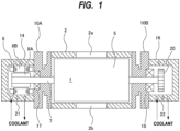
- FIG. 1 is a cross-sectional view showing an embodiment of a vacuum pump apparatus.
- the vacuum pump apparatus of the embodiment described below is a positive-displacement vacuum pump apparatus.
- the vacuum pump apparatus shown in FIG. 1 is a so-called dry vacuum pump apparatus that does not use oil in its flow passages for a gas. Since a vaporized oil does not flow to an upstream side, the dry vacuum pump apparatus can be suitably used for a semiconductor device manufacturing apparatus that requires high cleanliness.
- the vacuum pump apparatus includes a pump casing 2 having a rotor chamber 1 therein, pump rotors 5 arranged in the rotor chamber 1, rotation shafts 7 to which the pump rotors 5 are fixed, and an electric motor 8 coupled to the rotation shafts 7.
- the pump rotor 5 and the rotation shaft 7 may be an integral structure. Although only one pump rotor 5 and one rotation shaft 7 are depicted in FIG. 1 , a pair of pump rotors 5 are arranged in the rotor chamber 1, and are secured to a pair of rotation shafts 7, respectively.
- the electric motor 8 is coupled to one of the rotation shafts 7. In one embodiment, a pair of electric motors 8 may be coupled to the pair of rotation shafts 7, respectively.
- the pump rotors 5 of the present embodiment are Roots-type pump rotors, while the type of the pump rotors 5 is not limited to the present embodiment.
- the pump rotors 5 may be screw-type pump rotors.
- the pump rotors 5 of the present embodiment are single-stage pump rotors, in one embodiment the pump rotors 5 may be multistage pump rotors.
- the vacuum pump apparatus further includes side covers 10A and 10B located outwardly of the pump casing 2 in an axial direction of the rotation shafts 7.
- the side covers 10A and 10B are provided on both sides of the pump casing 2 and are coupled to the pump casing 2.
- the side covers 10A and 10B are fixed to end surfaces of the pump casing 2 by screws (not shown).
- the rotor chamber 1 is formed by an inner surface of the pump casing 2 and inner surfaces of the side covers 10A and 10B.
- the pump casing 2 has an intake port 2a and an exhaust port 2b.
- the intake port 2a is coupled to a chamber (not shown) filled with gas to be delivered.
- the intake port 2a may be coupled to a process chamber of a semiconductor-device manufacturing apparatus, and the vacuum pump apparatus may be used for evacuating a process gas that has been introduced into the process chamber.
- the vacuum pump apparatus further includes a motor housing 14 and a gear housing 16, which are housing structures located outwardly of the side covers 10A and 10B in the axial direction of the rotation shafts 7.
- the side cover 10A is located between the pump casing 2 and the motor housing 14, and the side cover 10B is located between the pump casing 2 and the gear housing 16.
- Each rotary shaft 7 is rotatably supported by a bearing 17 held by the side cover 10A and a bearing 18 held by the side cover 10B.
- the motor housing 14 accommodates a motor rotor 8A and a motor stator 8B of the electric motor 8 therein.
- the motor housing 14 and the gear housing 16 are examples of the housing structures, and the housing structures are not limited to this embodiment.
- the housing structure may be a bearing housing that holds the bearing.
- a pair of gears 20 that mesh with each other are arranged in the gear housing 16.
- the electric motor 8 is rotated by a motor driver (not shown), and one rotation shaft 7 that is coupled the electric motor 8 rotates the other rotation shaft 7 to which the electric motor 8 is not coupled in the opposite direction via the gears 20.
- a pair of electric motors 8 may be coupled to the pair of rotation shafts 7, respectively.
- the pair of motors 8 are synchronously rotated in opposite directions by a motor driver (not shown), so that the pair of rotation shafts 7 and the pair of pump rotors 5 are synchronously rotated in opposite directions.
- the role of the gears 20 in this case is to prevent out of the synchronous rotations of the pump rotors 5 due to a sudden external cause.
- a cooling flow passage 21 is provided in the motor housing 14.
- a cooling flow passage 22 is provided in the gear housing 16.
- the cooling flow passage 21 extends an entire peripheral wall of the motor housing 14, and the cooling flow passage 22 extends an entire peripheral wall of the gear housing 16.
- the cooling flow passage 21 and the cooling flow passage 22 are coupled to a coolant supply source (not shown).
- a coolant is supplied from the coolant supply source to the cooling flow passage 21 and the cooling flow passage 22.
- the coolant flowing through the cooling flow passage 21 can cool the motor housing 14, whereby the electric motor 8 and the bearings 17 arranged in the motor housing 14 can be cooled.
- the coolant flowing through the cooling flow passage 22 can cool the gear housing 16, whereby the gears 20 and the bearings 18 arranged in the gear housing 16 can be cooled.
- Some of the process gases to be handled by the vacuum pump apparatus of the present embodiment include by-product that is solidified as the temperature decreases.
- the process gas is compressed in the process of being transferred from the intake port 2a to the exhaust port 2b by the pump rotors 5. Therefore, the inside of the rotor chamber 1 becomes hot due to the heat of compression of the process gas.
- the side cover 10A is configured to reduce heat transfer from the pump casing 2 to the motor housing 14, and the side cover 10B is configured to reduce heat transfer from the pump casing 2 to the gear housing 16. Therefore, the side covers 10A and 10B can maintain the inside of the rotor chamber 1 at a high temperature. In particular, the side covers 10A and 10B can maintain the inside of the rotor chamber 1 at a high temperature while the motor housing 14 and the gear housing 16 are cooled by the coolant flowing through the cooling passages 21 and 22.
- the pump casing 2 and the side covers 10A and 10B forming the rotor chamber 1 are made of cast iron.
- the side covers 10A and 10B may be made of a material having a lower thermal conductivity than cast iron.
- FIG. 2 is a side view of the side cover 10A
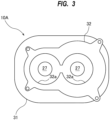
- FIG. 3 is a view seen from a direction indicated by arrow A in FIG. 2
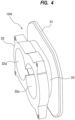
- FIG. 4 is a perspective view of the side cover 10A shown in FIG. 2 .
- the side cover 10A has through-holes 27 through which the rotation shafts 7 extend.
- the through-holes 27 communicate with the rotor chamber 1.
- the side cover 10A includes an inner wall portion 31 forming an end surface 31a of the rotor chamber 1, an outer wall portion 32 located outwardly of the inner wall portion 31 in the axial direction of the rotation shafts 7, and a narrow portion 33 located between the inner wall portion 31 and the outer wall portion 32.
- the inner wall portion 31 is coupled to the pump casing 2 (see FIG. 1 ), and the outer wall portion 32 is coupled to the motor housing 14.
- the outer wall portion 32 has recesses 32a in which the bearings 17 are housed.
- a heat insulating material may be arranged between the outer wall portion 32 and the motor housing 14.
- the inner wall portion 31, the outer wall portion 32, and the narrow portion 33 are an integrally-formed structure.
- the inner wall portion 31, the outer wall portion 32, and the narrow portion 33 are an integrally-formed casting.
- the side cover 10A since the side cover 10A includes the integrally-formed structure, it is not necessary to separately prepare a plurality of parts and assemble them. As a result, a manufacturing cost can be reduced.
- the narrow portion 33 has an outer peripheral length shorter than those of the inner wall portion 31 and the outer wall portion 32. Specifically, the narrow portion 33 has a cross-sectional area smaller than cross-sectional areas of the inner wall portion 31 and the outer wall portion 32.
- the inner wall portion 31, the outer wall portion 32, and the narrow portion 33 are made of the same material, but the cross-sectional area of the narrow portion 33 is smaller than the cross-sectional areas of the inner wall portion 31 and the outer wall portion 32. As a result, the heat is unlikely to be transferred from the inner wall portion 31 to the outer wall portion 32 through the narrow portion 33.
- the side cover 10B basically has the same configuration.
- the side covers 10A and 10B include the narrow portions 33 have a high heat insulation, the inside of the rotor chamber 1 can be maintained at a high temperature.
- the side covers 10A and 10B can prevent the pump casing 2 from being cooled by the coolant flowing through the cooling flow passage 21 and the cooling flow passage 22.
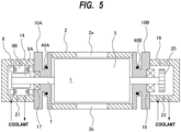
- FIG. 5 is a cross-sectional view showing another embodiment of the vacuum pump apparatus. Configurations of the present embodiment, which will not be particularly described, are the same as those of the embodiments described with reference to FIGS. 1 to 4 , and duplicate descriptions thereof will be omitted.
- the vacuum pump apparatus shown in FIG. 5 further includes heaters 40A and 40B arranged in the side covers 10A and 10B, respectively. The heaters 40A and 40B are removably mounted to the side covers 10A and 10B.
- FIG. 6 is a side view of the side cover 10A shown in FIG. 5
- FIG. 7 is a view seen from a direction indicated by arrow B in FIG. 6
- FIG. 8 is a perspective view of the side cover 10A shown in FIG. 6
- the side cover 10A has two heater housings 35 having holes 35a, respectively.
- the two heater housings 35, the inner wall portion 31, the outer wall portion 32, and the narrow portion 33 are an integrally-formed structure.
- Each hole 35a is open in an outer surface of the side cover 10A (more specifically, in an outer surface of the heater housing 35), and each heater 40A is arranged in each hole 35a.
- the two heaters 40A are arranged such that the rotation shafts 7 (see FIG. 5 ) are located between these two heaters 40A.
- only one heater 40A may be provided, or three or more heaters 40A may be provided.
- the hole 35a extends linearly, and the heater 40A is a rod-shaped heater that also extends linearly.
- the heater 40A is inserted into the hole 35a and fixed to the side cover 10A by a screw 45 which is a fixing mechanism. More specifically, the heater housing 35 has a screw hole 46 communicating with the hole 35a, and the screw 45 is screwed into the screw hole 46 until an end of the screw 45 presses the heater 40A in the hole 35a against the heater housing 35. As a result, the position of the heater 40A is fixed. When the screw 45 is loosened, the heater 40A can be removed from the hole 35a.
- the heater 40A can be removed from the side cover 10A without disassembling the vacuum pump apparatus. Therefore, the heater 40A can be easily replaced with a new heater in case the heater 40A gets out of order.
- the heat generated by the heater 40A is transferred to the rotor chamber 1 (see FIG. 5 ) through the heater housing 35 and the inner wall portion 31 to thereby heat the rotor chamber 1.
- the heater housing 35 and the inner wall portion 31 are integrally formed, an efficiency of the heat transfer from the heater 40A to the inner wall portion 31 is improved.
- the heater housing 35 is separated from the outer wall portion 32. Although not shown, the entire heater housing 35 may be separated from the outer wall portion 32. With such a configuration, the heat generated by the heater 40A is unlikely to be transferred to the outer wall portion 32. Therefore, the heater 40A hardly heats the motor housing 14 (see FIG. 5 ), which is a housing structure coupled to the outer wall portion 32, while the heater 40A can heat the rotor chamber 1.
- the heater 40B is also arranged in the side cover 10B.
- the descriptions with reference to FIGS. 6 to 8 can be applied to the side cover 10B and the heater 40B disposed in the side cover 10B, and repetitive descriptions thereof will be omitted.
- FIG. 9 is a cross-sectional view showing another embodiment of the vacuum pump apparatus. Configurations of the present embodiment, which will not be particularly described, are the same as those of the embodiments described with reference to FIGS. 1 to 4 , and duplicate descriptions thereof will be omitted.
- the vacuum pump apparatus shown in FIG. 9 includes cooling flow passages 21 and 22 provided in the motor housing 14 and the gear housing 16 which are housing structures, flow passage valves 51 and 52 coupled to the cooling flow passages, respectively, a temperature sensor 55 attached to the electric motor 8, a temperature sensor 56 attached to the side cover 10B, and a valve controller 60 configured to control operations of the flow passage valves 51 and 52 based on temperatures measured by the temperature sensors 55 and 56.
- the temperature sensor 55 is attached to the motor stator 8B of the electric motor 8, and the temperature sensor 56 is attached to the outer wall portion 32 (see FIGS. 2 to 4 ) coupled to the gear housing 16.
- the valve controller 60 is constituted by at least one computer.
- the temperature sensors 55, 56 and the flow passage valves 51, 52 are electrically coupled to the valve controller 60.
- the temperature sensor 55 attached to the electric motor 8 measures the temperature of the electric motor 8 and transmits a measured value of the temperature to the valve controller 60.
- the valve controller 60 is configured to open the flow passage valve 51 when the temperature of the electric motor 8 exceeds a predetermined threshold value and close the flow passage valve 51 when the temperature of the electric motor 8 falls below the threshold value.
- the temperature sensor 56 attached to the side cover 10B measures the temperature of the side cover 10B and transmits a measured value of the temperature to the valve controller 60.
- the valve controller 60 is configured to open the flow passage valve 52 when the temperature of the side cover 10B exceeds a predetermined threshold value and close the flow passage valve 52 when the temperature of the side cover 10B falls below the threshold value.
- the coolant flows through the cooling flow passage 21 in the motor housing 14 only when the temperature of the electric motor 8 exceeds the threshold value, so that excessive cooling of the side cover 10A by the coolant can be prevented.
- the coolant flows through the cooling flow passage 22 in the gear housing 16 only when the temperature of the side cover 10B exceeds the threshold value, so that excessive cooling of the side cover 10B by the coolant can be prevented.
- the temperature sensor 55 may be attached to the motor housing 14 or the outer wall portion 32 (see FIGS. 2 to 4 ) of the side cover 10A, instead of the electric motor 8.
- the valve controller 60 is configured to open the flow passage valve 51 when the temperature measured by the temperature sensor 55 exceeds a predetermined threshold value and close the flow passage valve 51 when the temperature measured by the temperature sensor 55 falls below the threshold value.
- the temperature sensor 56 may be attached to the gear housing 16, instead of the side cover 10B.
- the valve controller 60 is configured to open the flow passage valve 52 when the temperature measured by the temperature sensor 56 exceeds a predetermined threshold value and close the flow passage valve 52 when the temperature measured by the temperature sensor 56 falls below the threshold value.
- FIG. 9 may be combined with the embodiments described with reference to FIGS. 5 to 8 .
Landscapes
- Engineering & Computer Science (AREA)
- Mechanical Engineering (AREA)
- General Engineering & Computer Science (AREA)
- Applications Or Details Of Rotary Compressors (AREA)
- Rotary Pumps (AREA)
Claims (11)
- Vakuumpumpenvorrichtung, die Folgendes aufweist:ein Pumpengehäuse (2) mit einer Rotorkammer (1) darin;Pumpenrotoren (5), die in der Rotorkammer (1) angeordnet sind;Drehwellen (7), an denen die Pumpenrotoren (5) befestigt sind;Lager (17, 18), welche die Drehwellen (7) drehbar tragen;einen Elektromotor (8), der mit den Drehwellen (7) gekoppelt ist;eine Seitenabdeckung (10A, 10B), die eine Endfläche (31a) der Rotorkammer (1) bildet; undeine Gehäusestruktur (14, 16), die in einer axialen Richtung der Drehwellen (7) außerhalb der Seitenabdeckung (10A, 10B) angeordnet ist,wobei die Seitenabdeckung (10A, 10B) einen inneren Wandteil (31) aufweist, der die Endfläche (31a) der Rotorkammer (1) bildet, einen äußeren Wandteil (32), der in der axialen Richtung der Drehwellen (7) außerhalb des inneren Wandteils (31) angeordnet ist, und einen schmalen Teil (33), der zwischen dem inneren Wandteil (31) und dem äußeren Wandteil (32) angeordnet ist,wobei die Lager (17, 18) außerhalb des schmalen Teils (33) angeordnet sind und in Vertiefungen (32a) aufgenommen sind, die in dem äußeren Wandteil (32) geformt sind,wobei der innere Wandteil (31), der äußere Wandteil (32) und der schmale Teil (33) eine integral geformte Struktur sind, undwobei der schmale Teil (33) eine kleinere Querschnittsfläche hat als die Querschnittsflächen des inneren Wandteils (31) und des äußeren Wandteils (32).
- Vakuumpumpenvorrichtung nach Anspruch 1, die weiter eine Heizung (40A, 40B) aufweist, die in der Seitenabdeckung (10A, 10B) angeordnet ist.
- Vakuumpumpenvorrichtung nach Anspruch 2, wobei die Heizung (40A, 40B) in entfernbarer Weise an der Seitenabdeckung (10A, 10B) befestigt ist.
- Vakuumpumpenvorrichtung nach Anspruch 3, wobeidie Seitenabdeckung (10A, 10B) ein Heizungsgehäuse (35) mit einem Loch (35a) hat;wobei das Loch (35a) in einer Außenfläche der Seitenabdeckung (10A, 10B) offen ist; undwobei die Heizung (40A, 40B) in dem Loch (35a) angeordnet ist.
- Vakuumpumpenvorrichtung nach Anspruch 4, wobei das Loch (35a) sich linear erstreckt und die Heizung (40A, 40B) eine stabförmige Heizung ist.
- Vakuumpumpenvorrichtung nach Anspruch 4 oder 5, die weiter einen Befestigungsmechanismus (45) aufweist, der konfiguriert ist, um in entfernbarer Weise die Heizung (40A, 40B) an dem Heizungsgehäuse (35) zu befestigen.
- Vakuumpumpenvorrichtung nach einem der Ansprüche 4 bis 6, wobei das Heizungsgehäuse (35) mit dem inneren Wandteil (31) verbunden ist.
- Vakuumpumpenvorrichtung nach Anspruch 7, wobei zumindest ein Teil des Heizungsgehäuses (35) von dem äußeren Wandteil (32) getrennt ist.
- Vakuumpumpenvorrichtung nach einem der Ansprüche 1 bis 8, die weiter Folgendes aufweist:einen Kühlflussdurchlass (21, 22), der in der Gehäusestruktur (14, 16) vorgesehen ist;ein Flussdurchlassventil (51, 52), das mit dem Kühlflussdurchlass (21, 22) gekoppelt ist;einen Temperatursensor (55, 56), der an einem von Folgenden befestigt ist: dem Elektromotor (8), der Seitenabdeckung (10A, 10B), der Gehäusestruktur (14, 16); undeine Ventilsteuervorrichtung (60), die konfiguriert ist, um das Flussdurchlassventil (51, 52) zu öffnen, wenn eine Temperatur, die durch den Temperatursensor (55, 56) gemessen wird, einen Schwellenwert überschreitet, und um das Flussdurchlassventil (51, 52) zu schließen, wenn die Temperatur unter den Schwellenwert fällt.
- Vakuumpumpenvorrichtung nach einem der Ansprüche 1 bis 9, wobei der innere Wandteil (31) und der äußere Wandteil (33) voneinander getrennt sind.
- Vakuumpumpenvorrichtung nach Anspruch 5, wobei das sich linear erstreckende Loch (35a) senkrecht zu den Drehwellen (7) ist, und wobei die stabförmige Heizung (40A, 40B) in entfernbarer Weise in dem sich linear erstreckenden Loch (35a) angeordnet ist.
Applications Claiming Priority (1)
| Application Number | Priority Date | Filing Date | Title |
|---|---|---|---|
| JP2021054585A JP7555870B2 (ja) | 2021-03-29 | 2021-03-29 | 真空ポンプ装置 |
Publications (3)
| Publication Number | Publication Date |
|---|---|
| EP4067658A2 EP4067658A2 (de) | 2022-10-05 |
| EP4067658A3 EP4067658A3 (de) | 2022-11-02 |
| EP4067658B1 true EP4067658B1 (de) | 2025-02-12 |
Family
ID=81748387
Family Applications (1)
| Application Number | Title | Priority Date | Filing Date |
|---|---|---|---|
| EP22164110.3A Active EP4067658B1 (de) | 2021-03-29 | 2022-03-24 | Vakuumpumpengerät |
Country Status (5)
| Country | Link |
|---|---|
| EP (1) | EP4067658B1 (de) |
| JP (1) | JP7555870B2 (de) |
| KR (1) | KR20220136156A (de) |
| CN (1) | CN115143114A (de) |
| TW (1) | TW202244392A (de) |
Families Citing this family (1)
| Publication number | Priority date | Publication date | Assignee | Title |
|---|---|---|---|---|
| GB2630629B (en) * | 2023-06-01 | 2025-07-02 | Edwards Ltd | Vacuum pump |
Citations (35)
| Publication number | Priority date | Publication date | Assignee | Title |
|---|---|---|---|---|
| JPS52121810U (de) | 1976-03-13 | 1977-09-16 | ||
| JPS5884400U (ja) | 1981-12-04 | 1983-06-08 | 三菱重工業株式会社 | 拡散型ポンプ |
| JPH0342091U (de) | 1989-09-01 | 1991-04-22 | ||
| JPH0738688U (ja) | 1993-12-20 | 1995-07-14 | オリオン機械株式会社 | 無給油式回転ベーンポンプ |
| DE19702456A1 (de) | 1997-01-24 | 1998-07-30 | Pfeiffer Vacuum Gmbh | Vakuumpumpe |
| US6164945A (en) | 1998-02-13 | 2000-12-26 | Ebara Corporation | Vacuum pump rotor and method of manufacturing the same |
| DE19882987C2 (de) | 1998-03-31 | 2002-11-07 | Taiko Kikai Ind Co | Vakuumpumpe |
| WO2003081048A1 (de) | 2002-03-22 | 2003-10-02 | Leybold Vakuum Gmbh | Exzenterpumpe und verfahren zum betrieb dieser pumpe |
| WO2004038227A1 (de) | 2002-10-25 | 2004-05-06 | Rietschle Thomas Schopfheim Gmbh | Verdichtermaschine mit zwei gegensinnig laufenden rotoren |
| EP1741931A1 (de) | 2005-07-05 | 2007-01-10 | Aerzener Maschinenfabrik GmbH | Drehkolbenverdichter und Verfahren zu dessen Betrieb |
| JP2007262906A (ja) | 2006-03-27 | 2007-10-11 | Nabtesco Corp | 2段式真空ポンプ |
| EP1900943A1 (de) | 2006-09-12 | 2008-03-19 | Kabushiki Kaisha Toyota Jidoshokki | Verfahren zur Steuerung des Stoppbetriebs einer Vakuumpumpe und Vorrichtung dafür |
| JP2009052516A (ja) | 2007-08-29 | 2009-03-12 | Orion Mach Co Ltd | 回転ベーンポンプ |
| JP2009092042A (ja) | 2007-10-11 | 2009-04-30 | Nabtesco Corp | 回転ロータ式ポンプの軸受保護機構 |
| CN102852798A (zh) | 2012-08-14 | 2013-01-02 | 杭州新安江工业泵有限公司 | 罗茨真空泵冷却系统 |
| JP2013253502A (ja) | 2012-06-05 | 2013-12-19 | Shimadzu Corp | 真空ポンプ |
| DE102012213735A1 (de) | 2012-08-02 | 2014-02-27 | Robert Bosch Gmbh | Pumpe, insbesondere Verdrängerpumpe |
| CN103671087A (zh) | 2012-09-09 | 2014-03-26 | 王五一 | 带有旋移活塞结构的所有泵类和它类相关产品及部分实例 |
| CN203822629U (zh) | 2014-02-28 | 2014-09-10 | 东莞市雅之雷德机电科技有限公司 | 一种带冷却装置的罗茨真空泵 |
| CN204082556U (zh) | 2014-09-10 | 2015-01-07 | 山东省章丘鼓风机股份有限公司 | 一种逆流冷却干式罗茨真空泵 |
| JP2016118100A (ja) | 2014-12-18 | 2016-06-30 | 株式会社荏原製作所 | ドライ真空ポンプ、およびドライ真空ポンプの製造方法 |
| CN205478334U (zh) | 2016-02-02 | 2016-08-17 | 常州市华东真空泵厂 | 一种液冷型罗茨真空泵 |
| JP2016148281A (ja) | 2015-02-12 | 2016-08-18 | オリオン機械株式会社 | 二軸回転ポンプ |
| CN106704176A (zh) | 2016-12-02 | 2017-05-24 | 马德宝真空设备集团有限公司 | 一种罗茨泵的冷却系统 |
| CN107061284A (zh) | 2017-04-11 | 2017-08-18 | 浙江神工真空设备制造有限公司 | 一种罗茨真空泵 |
| US20180030983A1 (en) | 2015-09-24 | 2018-02-01 | In Cheol Lee | Vacuum pump with cooling apparatus |
| CN207470428U (zh) | 2017-11-27 | 2018-06-08 | 广东肯富来泵业股份有限公司 | 一种带有水冷隔层的罗茨泵 |
| WO2018169133A1 (ko) | 2017-03-15 | 2018-09-20 | 주식회사 플랜 | 반도체 챔버용 펌프 시스템 |
| KR101915976B1 (ko) | 2017-09-12 | 2018-11-07 | 한국원자력연구원 | 로터리 피스톤 펌프 및 그 구동 방법 |
| EP3499039A1 (de) | 2017-12-15 | 2019-06-19 | Pfeiffer Vacuum Gmbh | Schraubenvakuumpumpe |
| CN209370056U (zh) | 2018-12-31 | 2019-09-10 | 浙江创为真空设备股份有限公司 | 一种气冷式直排罗茨泵 |
| JP2020505541A (ja) | 2017-02-03 | 2020-02-20 | エドワーズ リミテッド | ポンプ冷却システム |
| JP2020063691A (ja) | 2018-10-17 | 2020-04-23 | 株式会社アンレット | ルーツブロワ |
| US20200173435A1 (en) | 2017-08-07 | 2020-06-04 | Ulvac, Inc. | Vacuum pump |
| WO2020255300A1 (ja) | 2019-06-19 | 2020-12-24 | 樫山工業株式会社 | 真空ポンプ |
Family Cites Families (5)
| Publication number | Priority date | Publication date | Assignee | Title |
|---|---|---|---|---|
| JPS5745418Y2 (de) * | 1976-12-08 | 1982-10-06 | ||
| JP4017365B2 (ja) | 2001-07-19 | 2007-12-05 | 株式会社荏原製作所 | ドライ真空ポンプ |
| JP2004293434A (ja) * | 2003-03-27 | 2004-10-21 | Aisin Seiki Co Ltd | ドライポンプ |
| JP5793004B2 (ja) | 2011-06-02 | 2015-10-14 | 株式会社荏原製作所 | 真空ポンプ |
| JP7281388B2 (ja) * | 2018-12-28 | 2023-05-25 | 株式会社荏原製作所 | 軸受装置および真空ポンプ装置 |
-
2021
- 2021-03-29 JP JP2021054585A patent/JP7555870B2/ja active Active
-
2022
- 2022-03-23 CN CN202210304826.1A patent/CN115143114A/zh active Pending
- 2022-03-23 TW TW111110862A patent/TW202244392A/zh unknown
- 2022-03-23 KR KR1020220035782A patent/KR20220136156A/ko active Pending
- 2022-03-24 EP EP22164110.3A patent/EP4067658B1/de active Active
Patent Citations (35)
| Publication number | Priority date | Publication date | Assignee | Title |
|---|---|---|---|---|
| JPS52121810U (de) | 1976-03-13 | 1977-09-16 | ||
| JPS5884400U (ja) | 1981-12-04 | 1983-06-08 | 三菱重工業株式会社 | 拡散型ポンプ |
| JPH0342091U (de) | 1989-09-01 | 1991-04-22 | ||
| JPH0738688U (ja) | 1993-12-20 | 1995-07-14 | オリオン機械株式会社 | 無給油式回転ベーンポンプ |
| DE19702456A1 (de) | 1997-01-24 | 1998-07-30 | Pfeiffer Vacuum Gmbh | Vakuumpumpe |
| US6164945A (en) | 1998-02-13 | 2000-12-26 | Ebara Corporation | Vacuum pump rotor and method of manufacturing the same |
| DE19882987C2 (de) | 1998-03-31 | 2002-11-07 | Taiko Kikai Ind Co | Vakuumpumpe |
| WO2003081048A1 (de) | 2002-03-22 | 2003-10-02 | Leybold Vakuum Gmbh | Exzenterpumpe und verfahren zum betrieb dieser pumpe |
| WO2004038227A1 (de) | 2002-10-25 | 2004-05-06 | Rietschle Thomas Schopfheim Gmbh | Verdichtermaschine mit zwei gegensinnig laufenden rotoren |
| EP1741931A1 (de) | 2005-07-05 | 2007-01-10 | Aerzener Maschinenfabrik GmbH | Drehkolbenverdichter und Verfahren zu dessen Betrieb |
| JP2007262906A (ja) | 2006-03-27 | 2007-10-11 | Nabtesco Corp | 2段式真空ポンプ |
| EP1900943A1 (de) | 2006-09-12 | 2008-03-19 | Kabushiki Kaisha Toyota Jidoshokki | Verfahren zur Steuerung des Stoppbetriebs einer Vakuumpumpe und Vorrichtung dafür |
| JP2009052516A (ja) | 2007-08-29 | 2009-03-12 | Orion Mach Co Ltd | 回転ベーンポンプ |
| JP2009092042A (ja) | 2007-10-11 | 2009-04-30 | Nabtesco Corp | 回転ロータ式ポンプの軸受保護機構 |
| JP2013253502A (ja) | 2012-06-05 | 2013-12-19 | Shimadzu Corp | 真空ポンプ |
| DE102012213735A1 (de) | 2012-08-02 | 2014-02-27 | Robert Bosch Gmbh | Pumpe, insbesondere Verdrängerpumpe |
| CN102852798A (zh) | 2012-08-14 | 2013-01-02 | 杭州新安江工业泵有限公司 | 罗茨真空泵冷却系统 |
| CN103671087A (zh) | 2012-09-09 | 2014-03-26 | 王五一 | 带有旋移活塞结构的所有泵类和它类相关产品及部分实例 |
| CN203822629U (zh) | 2014-02-28 | 2014-09-10 | 东莞市雅之雷德机电科技有限公司 | 一种带冷却装置的罗茨真空泵 |
| CN204082556U (zh) | 2014-09-10 | 2015-01-07 | 山东省章丘鼓风机股份有限公司 | 一种逆流冷却干式罗茨真空泵 |
| JP2016118100A (ja) | 2014-12-18 | 2016-06-30 | 株式会社荏原製作所 | ドライ真空ポンプ、およびドライ真空ポンプの製造方法 |
| JP2016148281A (ja) | 2015-02-12 | 2016-08-18 | オリオン機械株式会社 | 二軸回転ポンプ |
| US20180030983A1 (en) | 2015-09-24 | 2018-02-01 | In Cheol Lee | Vacuum pump with cooling apparatus |
| CN205478334U (zh) | 2016-02-02 | 2016-08-17 | 常州市华东真空泵厂 | 一种液冷型罗茨真空泵 |
| CN106704176A (zh) | 2016-12-02 | 2017-05-24 | 马德宝真空设备集团有限公司 | 一种罗茨泵的冷却系统 |
| JP2020505541A (ja) | 2017-02-03 | 2020-02-20 | エドワーズ リミテッド | ポンプ冷却システム |
| WO2018169133A1 (ko) | 2017-03-15 | 2018-09-20 | 주식회사 플랜 | 반도체 챔버용 펌프 시스템 |
| CN107061284A (zh) | 2017-04-11 | 2017-08-18 | 浙江神工真空设备制造有限公司 | 一种罗茨真空泵 |
| US20200173435A1 (en) | 2017-08-07 | 2020-06-04 | Ulvac, Inc. | Vacuum pump |
| KR101915976B1 (ko) | 2017-09-12 | 2018-11-07 | 한국원자력연구원 | 로터리 피스톤 펌프 및 그 구동 방법 |
| CN207470428U (zh) | 2017-11-27 | 2018-06-08 | 广东肯富来泵业股份有限公司 | 一种带有水冷隔层的罗茨泵 |
| EP3499039A1 (de) | 2017-12-15 | 2019-06-19 | Pfeiffer Vacuum Gmbh | Schraubenvakuumpumpe |
| JP2020063691A (ja) | 2018-10-17 | 2020-04-23 | 株式会社アンレット | ルーツブロワ |
| CN209370056U (zh) | 2018-12-31 | 2019-09-10 | 浙江创为真空设备股份有限公司 | 一种气冷式直排罗茨泵 |
| WO2020255300A1 (ja) | 2019-06-19 | 2020-12-24 | 樫山工業株式会社 | 真空ポンプ |
Also Published As
| Publication number | Publication date |
|---|---|
| JP7555870B2 (ja) | 2024-09-25 |
| CN115143114A (zh) | 2022-10-04 |
| JP2022151996A (ja) | 2022-10-12 |
| TW202244392A (zh) | 2022-11-16 |
| KR20220136156A (ko) | 2022-10-07 |
| EP4067658A2 (de) | 2022-10-05 |
| EP4067658A3 (de) | 2022-11-02 |
Similar Documents
| Publication | Publication Date | Title |
|---|---|---|
| EP3808982B1 (de) | Vakuumpumpe mit thermischer isolierung | |
| CN111836968A (zh) | 真空泵 | |
| JP2021063503A (ja) | 真空ポンプ装置 | |
| KR101760549B1 (ko) | 진공 펌프 | |
| EP2378122B1 (de) | Trockenvakuumpumpenvorrichtung und Kühlverfahren dafür | |
| JP4594689B2 (ja) | 真空ポンプ | |
| EP4067658B1 (de) | Vakuumpumpengerät | |
| EP3808983B1 (de) | Vakuumpumpe mit heizung im seitendeckel | |
| EP4177465B1 (de) | Vakuumpumpenvorrichtung | |
| JPH0893687A (ja) | 真空ポンプ装置 | |
| EP4198315A1 (de) | Vakuumpumpenvorrichtung und verfahren zum betrieb davon | |
| WO2010061939A1 (ja) | ドライ真空ポンプユニット | |
| KR101487021B1 (ko) | 펌핑 유닛 및 대응하는 가열 장치 | |
| JP5133224B2 (ja) | 真空ポンプユニット | |
| JP2015004326A (ja) | 真空ポンプ装置 | |
| JP2010127157A5 (de) | ||
| JP2025148682A (ja) | 真空ポンプおよび真空ポンプ冷却システム | |
| JP3273959B2 (ja) | モータの冷却装置 |
Legal Events
| Date | Code | Title | Description |
|---|---|---|---|
| PUAI | Public reference made under article 153(3) epc to a published international application that has entered the european phase |
Free format text: ORIGINAL CODE: 0009012 |
|
| STAA | Information on the status of an ep patent application or granted ep patent |
Free format text: STATUS: THE APPLICATION HAS BEEN PUBLISHED |
|
| PUAL | Search report despatched |
Free format text: ORIGINAL CODE: 0009013 |
|
| AK | Designated contracting states |
Kind code of ref document: A2 Designated state(s): AL AT BE BG CH CY CZ DE DK EE ES FI FR GB GR HR HU IE IS IT LI LT LU LV MC MK MT NL NO PL PT RO RS SE SI SK SM TR |
|
| AK | Designated contracting states |
Kind code of ref document: A3 Designated state(s): AL AT BE BG CH CY CZ DE DK EE ES FI FR GB GR HR HU IE IS IT LI LT LU LV MC MK MT NL NO PL PT RO RS SE SI SK SM TR |
|
| RIC1 | Information provided on ipc code assigned before grant |
Ipc: F04C 18/16 20060101ALI20220923BHEP Ipc: F04C 29/04 20060101ALI20220923BHEP Ipc: F04C 25/02 20060101ALI20220923BHEP Ipc: F04C 18/12 20060101ALI20220923BHEP Ipc: F04C 18/08 20060101AFI20220923BHEP |
|
| STAA | Information on the status of an ep patent application or granted ep patent |
Free format text: STATUS: REQUEST FOR EXAMINATION WAS MADE |
|
| 17P | Request for examination filed |
Effective date: 20230502 |
|
| RBV | Designated contracting states (corrected) |
Designated state(s): AL AT BE BG CH CY CZ DE DK EE ES FI FR GB GR HR HU IE IS IT LI LT LU LV MC MK MT NL NO PL PT RO RS SE SI SK SM TR |
|
| RAP3 | Party data changed (applicant data changed or rights of an application transferred) |
Owner name: EBARA CORPORATION |
|
| GRAP | Despatch of communication of intention to grant a patent |
Free format text: ORIGINAL CODE: EPIDOSNIGR1 |
|
| STAA | Information on the status of an ep patent application or granted ep patent |
Free format text: STATUS: GRANT OF PATENT IS INTENDED |
|
| RIC1 | Information provided on ipc code assigned before grant |
Ipc: F04C 18/16 20060101ALI20240731BHEP Ipc: F04C 29/04 20060101ALI20240731BHEP Ipc: F04C 25/02 20060101ALI20240731BHEP Ipc: F04C 18/12 20060101ALI20240731BHEP Ipc: F04C 18/08 20060101AFI20240731BHEP |
|
| INTG | Intention to grant announced |
Effective date: 20240827 |
|
| GRAS | Grant fee paid |
Free format text: ORIGINAL CODE: EPIDOSNIGR3 |
|
| GRAA | (expected) grant |
Free format text: ORIGINAL CODE: 0009210 |
|
| STAA | Information on the status of an ep patent application or granted ep patent |
Free format text: STATUS: THE PATENT HAS BEEN GRANTED |
|
| P01 | Opt-out of the competence of the unified patent court (upc) registered |
Free format text: CASE NUMBER: APP_64750/2024 Effective date: 20241206 |
|
| AK | Designated contracting states |
Kind code of ref document: B1 Designated state(s): AL AT BE BG CH CY CZ DE DK EE ES FI FR GB GR HR HU IE IS IT LI LT LU LV MC MK MT NL NO PL PT RO RS SE SI SK SM TR |
|
| REG | Reference to a national code |
Ref country code: GB Ref legal event code: FG4D |
|
| REG | Reference to a national code |
Ref country code: CH Ref legal event code: EP |
|
| REG | Reference to a national code |
Ref country code: DE Ref legal event code: R096 Ref document number: 602022010351 Country of ref document: DE |
|
| REG | Reference to a national code |
Ref country code: IE Ref legal event code: FG4D |
|
| PGFP | Annual fee paid to national office [announced via postgrant information from national office to epo] |
Ref country code: DE Payment date: 20250327 Year of fee payment: 4 |
|
| PGFP | Annual fee paid to national office [announced via postgrant information from national office to epo] |
Ref country code: AT Payment date: 20250417 Year of fee payment: 4 |
|
| PGFP | Annual fee paid to national office [announced via postgrant information from national office to epo] |
Ref country code: FR Payment date: 20250326 Year of fee payment: 4 Ref country code: CZ Payment date: 20250307 Year of fee payment: 4 |
|
| REG | Reference to a national code |
Ref country code: NL Ref legal event code: MP Effective date: 20250212 |
|
| PG25 | Lapsed in a contracting state [announced via postgrant information from national office to epo] |
Ref country code: RS Free format text: LAPSE BECAUSE OF FAILURE TO SUBMIT A TRANSLATION OF THE DESCRIPTION OR TO PAY THE FEE WITHIN THE PRESCRIBED TIME-LIMIT Effective date: 20250512 |
|
| PG25 | Lapsed in a contracting state [announced via postgrant information from national office to epo] |
Ref country code: FI Free format text: LAPSE BECAUSE OF FAILURE TO SUBMIT A TRANSLATION OF THE DESCRIPTION OR TO PAY THE FEE WITHIN THE PRESCRIBED TIME-LIMIT Effective date: 20250212 |
|
| PG25 | Lapsed in a contracting state [announced via postgrant information from national office to epo] |
Ref country code: PL Free format text: LAPSE BECAUSE OF FAILURE TO SUBMIT A TRANSLATION OF THE DESCRIPTION OR TO PAY THE FEE WITHIN THE PRESCRIBED TIME-LIMIT Effective date: 20250212 |
|
| PG25 | Lapsed in a contracting state [announced via postgrant information from national office to epo] |
Ref country code: ES Free format text: LAPSE BECAUSE OF FAILURE TO SUBMIT A TRANSLATION OF THE DESCRIPTION OR TO PAY THE FEE WITHIN THE PRESCRIBED TIME-LIMIT Effective date: 20250212 |
|
| REG | Reference to a national code |
Ref country code: LT Ref legal event code: MG9D |
|
| PG25 | Lapsed in a contracting state [announced via postgrant information from national office to epo] |
Ref country code: IS Free format text: LAPSE BECAUSE OF FAILURE TO SUBMIT A TRANSLATION OF THE DESCRIPTION OR TO PAY THE FEE WITHIN THE PRESCRIBED TIME-LIMIT Effective date: 20250612 Ref country code: NO Free format text: LAPSE BECAUSE OF FAILURE TO SUBMIT A TRANSLATION OF THE DESCRIPTION OR TO PAY THE FEE WITHIN THE PRESCRIBED TIME-LIMIT Effective date: 20250512 |
|
| PG25 | Lapsed in a contracting state [announced via postgrant information from national office to epo] |
Ref country code: NL Free format text: LAPSE BECAUSE OF FAILURE TO SUBMIT A TRANSLATION OF THE DESCRIPTION OR TO PAY THE FEE WITHIN THE PRESCRIBED TIME-LIMIT Effective date: 20250212 |
|
| PG25 | Lapsed in a contracting state [announced via postgrant information from national office to epo] |
Ref country code: HR Free format text: LAPSE BECAUSE OF FAILURE TO SUBMIT A TRANSLATION OF THE DESCRIPTION OR TO PAY THE FEE WITHIN THE PRESCRIBED TIME-LIMIT Effective date: 20250212 |
|
| PG25 | Lapsed in a contracting state [announced via postgrant information from national office to epo] |
Ref country code: PT Free format text: LAPSE BECAUSE OF FAILURE TO SUBMIT A TRANSLATION OF THE DESCRIPTION OR TO PAY THE FEE WITHIN THE PRESCRIBED TIME-LIMIT Effective date: 20250612 Ref country code: LV Free format text: LAPSE BECAUSE OF FAILURE TO SUBMIT A TRANSLATION OF THE DESCRIPTION OR TO PAY THE FEE WITHIN THE PRESCRIBED TIME-LIMIT Effective date: 20250212 |
|
| PG25 | Lapsed in a contracting state [announced via postgrant information from national office to epo] |
Ref country code: GR Free format text: LAPSE BECAUSE OF FAILURE TO SUBMIT A TRANSLATION OF THE DESCRIPTION OR TO PAY THE FEE WITHIN THE PRESCRIBED TIME-LIMIT Effective date: 20250513 Ref country code: BG Free format text: LAPSE BECAUSE OF FAILURE TO SUBMIT A TRANSLATION OF THE DESCRIPTION OR TO PAY THE FEE WITHIN THE PRESCRIBED TIME-LIMIT Effective date: 20250212 |
|
| PG25 | Lapsed in a contracting state [announced via postgrant information from national office to epo] |
Ref country code: AT Free format text: LAPSE BECAUSE OF FAILURE TO SUBMIT A TRANSLATION OF THE DESCRIPTION OR TO PAY THE FEE WITHIN THE PRESCRIBED TIME-LIMIT Effective date: 20250212 |
|
| REG | Reference to a national code |
Ref country code: AT Ref legal event code: MK05 Ref document number: 1766258 Country of ref document: AT Kind code of ref document: T Effective date: 20250212 |
|
| PG25 | Lapsed in a contracting state [announced via postgrant information from national office to epo] |
Ref country code: SE Free format text: LAPSE BECAUSE OF FAILURE TO SUBMIT A TRANSLATION OF THE DESCRIPTION OR TO PAY THE FEE WITHIN THE PRESCRIBED TIME-LIMIT Effective date: 20250212 |
|
| PG25 | Lapsed in a contracting state [announced via postgrant information from national office to epo] |
Ref country code: SM Free format text: LAPSE BECAUSE OF FAILURE TO SUBMIT A TRANSLATION OF THE DESCRIPTION OR TO PAY THE FEE WITHIN THE PRESCRIBED TIME-LIMIT Effective date: 20250212 |
|
| PG25 | Lapsed in a contracting state [announced via postgrant information from national office to epo] |
Ref country code: DK Free format text: LAPSE BECAUSE OF FAILURE TO SUBMIT A TRANSLATION OF THE DESCRIPTION OR TO PAY THE FEE WITHIN THE PRESCRIBED TIME-LIMIT Effective date: 20250212 |
|
| PG25 | Lapsed in a contracting state [announced via postgrant information from national office to epo] |
Ref country code: IT Free format text: LAPSE BECAUSE OF FAILURE TO SUBMIT A TRANSLATION OF THE DESCRIPTION OR TO PAY THE FEE WITHIN THE PRESCRIBED TIME-LIMIT Effective date: 20250212 |
|
| PG25 | Lapsed in a contracting state [announced via postgrant information from national office to epo] |
Ref country code: EE Free format text: LAPSE BECAUSE OF FAILURE TO SUBMIT A TRANSLATION OF THE DESCRIPTION OR TO PAY THE FEE WITHIN THE PRESCRIBED TIME-LIMIT Effective date: 20250212 |
|
| REG | Reference to a national code |
Ref country code: CH Ref legal event code: H13 Free format text: ST27 STATUS EVENT CODE: U-0-0-H10-H13 (AS PROVIDED BY THE NATIONAL OFFICE) Effective date: 20251023 |
|
| PG25 | Lapsed in a contracting state [announced via postgrant information from national office to epo] |
Ref country code: RO Free format text: LAPSE BECAUSE OF FAILURE TO SUBMIT A TRANSLATION OF THE DESCRIPTION OR TO PAY THE FEE WITHIN THE PRESCRIBED TIME-LIMIT Effective date: 20250212 |
|
| PG25 | Lapsed in a contracting state [announced via postgrant information from national office to epo] |
Ref country code: SK Free format text: LAPSE BECAUSE OF FAILURE TO SUBMIT A TRANSLATION OF THE DESCRIPTION OR TO PAY THE FEE WITHIN THE PRESCRIBED TIME-LIMIT Effective date: 20250212 |
|
| REG | Reference to a national code |
Ref country code: DE Ref legal event code: R026 Ref document number: 602022010351 Country of ref document: DE |
|
| PLBI | Opposition filed |
Free format text: ORIGINAL CODE: 0009260 |
|
| PG25 | Lapsed in a contracting state [announced via postgrant information from national office to epo] |
Ref country code: LU Free format text: LAPSE BECAUSE OF NON-PAYMENT OF DUE FEES Effective date: 20250324 |
|
| PLAX | Notice of opposition and request to file observation + time limit sent |
Free format text: ORIGINAL CODE: EPIDOSNOBS2 |
|
| 26 | Opposition filed |
Opponent name: PFEIFFER VACUUM GMBH Effective date: 20251105 |