EP4177465B1 - Vakuumpumpenvorrichtung - Google Patents
Vakuumpumpenvorrichtung Download PDFInfo
- Publication number
- EP4177465B1 EP4177465B1 EP22205764.8A EP22205764A EP4177465B1 EP 4177465 B1 EP4177465 B1 EP 4177465B1 EP 22205764 A EP22205764 A EP 22205764A EP 4177465 B1 EP4177465 B1 EP 4177465B1
- Authority
- EP
- European Patent Office
- Prior art keywords
- heater
- casing
- cartridge
- side cover
- pump
- Prior art date
- Legal status (The legal status is an assumption and is not a legal conclusion. Google has not performed a legal analysis and makes no representation as to the accuracy of the status listed.)
- Active
Links
Images


Classifications
-
- F—MECHANICAL ENGINEERING; LIGHTING; HEATING; WEAPONS; BLASTING
- F04—POSITIVE - DISPLACEMENT MACHINES FOR LIQUIDS; PUMPS FOR LIQUIDS OR ELASTIC FLUIDS
- F04B—POSITIVE-DISPLACEMENT MACHINES FOR LIQUIDS; PUMPS
- F04B37/00—Pumps having pertinent characteristics not provided for in, or of interest apart from, groups F04B25/00 - F04B35/00
- F04B37/10—Pumps having pertinent characteristics not provided for in, or of interest apart from, groups F04B25/00 - F04B35/00 for special use
- F04B37/14—Pumps having pertinent characteristics not provided for in, or of interest apart from, groups F04B25/00 - F04B35/00 for special use to obtain high vacuum
-
- F—MECHANICAL ENGINEERING; LIGHTING; HEATING; WEAPONS; BLASTING
- F04—POSITIVE - DISPLACEMENT MACHINES FOR LIQUIDS; PUMPS FOR LIQUIDS OR ELASTIC FLUIDS
- F04B—POSITIVE-DISPLACEMENT MACHINES FOR LIQUIDS; PUMPS
- F04B53/00—Component parts, details or accessories not provided for in, or of interest apart from, groups F04B1/00 - F04B23/00 or F04B39/00 - F04B47/00
- F04B53/08—Cooling; Heating; Preventing freezing
-
- F—MECHANICAL ENGINEERING; LIGHTING; HEATING; WEAPONS; BLASTING
- F04—POSITIVE - DISPLACEMENT MACHINES FOR LIQUIDS; PUMPS FOR LIQUIDS OR ELASTIC FLUIDS
- F04C—ROTARY-PISTON, OR OSCILLATING-PISTON, POSITIVE-DISPLACEMENT MACHINES FOR LIQUIDS; ROTARY-PISTON, OR OSCILLATING-PISTON, POSITIVE-DISPLACEMENT PUMPS
- F04C18/00—Rotary-piston pumps specially adapted for elastic fluids
- F04C18/08—Rotary-piston pumps specially adapted for elastic fluids of intermeshing-engagement type, i.e. with engagement of co-operating members similar to that of toothed gearing
- F04C18/12—Rotary-piston pumps specially adapted for elastic fluids of intermeshing-engagement type, i.e. with engagement of co-operating members similar to that of toothed gearing of other than internal-axis type
- F04C18/126—Rotary-piston pumps specially adapted for elastic fluids of intermeshing-engagement type, i.e. with engagement of co-operating members similar to that of toothed gearing of other than internal-axis type with radially from the rotor body extending elements, not necessarily co-operating with corresponding recesses in the other rotor, e.g. lobes, Roots type
-
- F—MECHANICAL ENGINEERING; LIGHTING; HEATING; WEAPONS; BLASTING
- F04—POSITIVE - DISPLACEMENT MACHINES FOR LIQUIDS; PUMPS FOR LIQUIDS OR ELASTIC FLUIDS
- F04C—ROTARY-PISTON, OR OSCILLATING-PISTON, POSITIVE-DISPLACEMENT MACHINES FOR LIQUIDS; ROTARY-PISTON, OR OSCILLATING-PISTON, POSITIVE-DISPLACEMENT PUMPS
- F04C18/00—Rotary-piston pumps specially adapted for elastic fluids
- F04C18/08—Rotary-piston pumps specially adapted for elastic fluids of intermeshing-engagement type, i.e. with engagement of co-operating members similar to that of toothed gearing
- F04C18/12—Rotary-piston pumps specially adapted for elastic fluids of intermeshing-engagement type, i.e. with engagement of co-operating members similar to that of toothed gearing of other than internal-axis type
- F04C18/14—Rotary-piston pumps specially adapted for elastic fluids of intermeshing-engagement type, i.e. with engagement of co-operating members similar to that of toothed gearing of other than internal-axis type with toothed rotary pistons
- F04C18/16—Rotary-piston pumps specially adapted for elastic fluids of intermeshing-engagement type, i.e. with engagement of co-operating members similar to that of toothed gearing of other than internal-axis type with toothed rotary pistons with helical teeth, e.g. chevron-shaped, screw type
-
- F—MECHANICAL ENGINEERING; LIGHTING; HEATING; WEAPONS; BLASTING
- F04—POSITIVE - DISPLACEMENT MACHINES FOR LIQUIDS; PUMPS FOR LIQUIDS OR ELASTIC FLUIDS
- F04C—ROTARY-PISTON, OR OSCILLATING-PISTON, POSITIVE-DISPLACEMENT MACHINES FOR LIQUIDS; ROTARY-PISTON, OR OSCILLATING-PISTON, POSITIVE-DISPLACEMENT PUMPS
- F04C23/00—Combinations of two or more pumps, each being of rotary-piston or oscillating-piston type, specially adapted for elastic fluids; Pumping installations specially adapted for elastic fluids; Multi-stage pumps specially adapted for elastic fluids
- F04C23/02—Pumps characterised by combination with, or adaptation to, specific driving engines or motors
-
- F—MECHANICAL ENGINEERING; LIGHTING; HEATING; WEAPONS; BLASTING
- F04—POSITIVE - DISPLACEMENT MACHINES FOR LIQUIDS; PUMPS FOR LIQUIDS OR ELASTIC FLUIDS
- F04C—ROTARY-PISTON, OR OSCILLATING-PISTON, POSITIVE-DISPLACEMENT MACHINES FOR LIQUIDS; ROTARY-PISTON, OR OSCILLATING-PISTON, POSITIVE-DISPLACEMENT PUMPS
- F04C25/00—Adaptations of pumps for special use of pumps for elastic fluids
- F04C25/02—Adaptations of pumps for special use of pumps for elastic fluids for producing high vacuum
-
- F—MECHANICAL ENGINEERING; LIGHTING; HEATING; WEAPONS; BLASTING
- F04—POSITIVE - DISPLACEMENT MACHINES FOR LIQUIDS; PUMPS FOR LIQUIDS OR ELASTIC FLUIDS
- F04C—ROTARY-PISTON, OR OSCILLATING-PISTON, POSITIVE-DISPLACEMENT MACHINES FOR LIQUIDS; ROTARY-PISTON, OR OSCILLATING-PISTON, POSITIVE-DISPLACEMENT PUMPS
- F04C29/00—Component parts, details or accessories of pumps or pumping installations, not provided for in groups F04C18/00 - F04C28/00
- F04C29/0042—Driving elements, brakes, couplings, transmissions specially adapted for pumps
- F04C29/0085—Prime movers
-
- F—MECHANICAL ENGINEERING; LIGHTING; HEATING; WEAPONS; BLASTING
- F04—POSITIVE - DISPLACEMENT MACHINES FOR LIQUIDS; PUMPS FOR LIQUIDS OR ELASTIC FLUIDS
- F04C—ROTARY-PISTON, OR OSCILLATING-PISTON, POSITIVE-DISPLACEMENT MACHINES FOR LIQUIDS; ROTARY-PISTON, OR OSCILLATING-PISTON, POSITIVE-DISPLACEMENT PUMPS
- F04C29/00—Component parts, details or accessories of pumps or pumping installations, not provided for in groups F04C18/00 - F04C28/00
- F04C29/04—Heating; Cooling; Heat insulation
-
- F—MECHANICAL ENGINEERING; LIGHTING; HEATING; WEAPONS; BLASTING
- F04—POSITIVE - DISPLACEMENT MACHINES FOR LIQUIDS; PUMPS FOR LIQUIDS OR ELASTIC FLUIDS
- F04C—ROTARY-PISTON, OR OSCILLATING-PISTON, POSITIVE-DISPLACEMENT MACHINES FOR LIQUIDS; ROTARY-PISTON, OR OSCILLATING-PISTON, POSITIVE-DISPLACEMENT PUMPS
- F04C2220/00—Application
- F04C2220/10—Vacuum
-
- F—MECHANICAL ENGINEERING; LIGHTING; HEATING; WEAPONS; BLASTING
- F04—POSITIVE - DISPLACEMENT MACHINES FOR LIQUIDS; PUMPS FOR LIQUIDS OR ELASTIC FLUIDS
- F04C—ROTARY-PISTON, OR OSCILLATING-PISTON, POSITIVE-DISPLACEMENT MACHINES FOR LIQUIDS; ROTARY-PISTON, OR OSCILLATING-PISTON, POSITIVE-DISPLACEMENT PUMPS
- F04C2240/00—Components
- F04C2240/20—Rotors
-
- F—MECHANICAL ENGINEERING; LIGHTING; HEATING; WEAPONS; BLASTING
- F04—POSITIVE - DISPLACEMENT MACHINES FOR LIQUIDS; PUMPS FOR LIQUIDS OR ELASTIC FLUIDS
- F04C—ROTARY-PISTON, OR OSCILLATING-PISTON, POSITIVE-DISPLACEMENT MACHINES FOR LIQUIDS; ROTARY-PISTON, OR OSCILLATING-PISTON, POSITIVE-DISPLACEMENT PUMPS
- F04C2240/00—Components
- F04C2240/30—Casings or housings
-
- F—MECHANICAL ENGINEERING; LIGHTING; HEATING; WEAPONS; BLASTING
- F04—POSITIVE - DISPLACEMENT MACHINES FOR LIQUIDS; PUMPS FOR LIQUIDS OR ELASTIC FLUIDS
- F04C—ROTARY-PISTON, OR OSCILLATING-PISTON, POSITIVE-DISPLACEMENT MACHINES FOR LIQUIDS; ROTARY-PISTON, OR OSCILLATING-PISTON, POSITIVE-DISPLACEMENT PUMPS
- F04C2240/00—Components
- F04C2240/40—Electric motor
-
- F—MECHANICAL ENGINEERING; LIGHTING; HEATING; WEAPONS; BLASTING
- F04—POSITIVE - DISPLACEMENT MACHINES FOR LIQUIDS; PUMPS FOR LIQUIDS OR ELASTIC FLUIDS
- F04C—ROTARY-PISTON, OR OSCILLATING-PISTON, POSITIVE-DISPLACEMENT MACHINES FOR LIQUIDS; ROTARY-PISTON, OR OSCILLATING-PISTON, POSITIVE-DISPLACEMENT PUMPS
- F04C2240/00—Components
- F04C2240/60—Shafts
-
- F—MECHANICAL ENGINEERING; LIGHTING; HEATING; WEAPONS; BLASTING
- F05—INDEXING SCHEMES RELATING TO ENGINES OR PUMPS IN VARIOUS SUBCLASSES OF CLASSES F01-F04
- F05C—INDEXING SCHEME RELATING TO MATERIALS, MATERIAL PROPERTIES OR MATERIAL CHARACTERISTICS FOR MACHINES, ENGINES OR PUMPS OTHER THAN NON-POSITIVE-DISPLACEMENT MACHINES OR ENGINES
- F05C2201/00—Metals
- F05C2201/02—Light metals
- F05C2201/021—Aluminium
-
- F—MECHANICAL ENGINEERING; LIGHTING; HEATING; WEAPONS; BLASTING
- F05—INDEXING SCHEMES RELATING TO ENGINES OR PUMPS IN VARIOUS SUBCLASSES OF CLASSES F01-F04
- F05C—INDEXING SCHEME RELATING TO MATERIALS, MATERIAL PROPERTIES OR MATERIAL CHARACTERISTICS FOR MACHINES, ENGINES OR PUMPS OTHER THAN NON-POSITIVE-DISPLACEMENT MACHINES OR ENGINES
- F05C2201/00—Metals
- F05C2201/02—Light metals
- F05C2201/028—Magnesium
-
- F—MECHANICAL ENGINEERING; LIGHTING; HEATING; WEAPONS; BLASTING
- F05—INDEXING SCHEMES RELATING TO ENGINES OR PUMPS IN VARIOUS SUBCLASSES OF CLASSES F01-F04
- F05C—INDEXING SCHEME RELATING TO MATERIALS, MATERIAL PROPERTIES OR MATERIAL CHARACTERISTICS FOR MACHINES, ENGINES OR PUMPS OTHER THAN NON-POSITIVE-DISPLACEMENT MACHINES OR ENGINES
- F05C2201/00—Metals
- F05C2201/04—Heavy metals
- F05C2201/0469—Other heavy metals
- F05C2201/0475—Copper or alloys thereof
Definitions
- the present invention relates to a vacuum pump apparatus, and more particularly to a vacuum pump apparatus suitable for use in exhausting a process gas used in manufacturing of semiconductor devices, liquid crystals, LEDs, solar cells, or the like.
- a process gas is introduced into a process chamber to perform a certain type of process, such as etching process or CVD process.
- the process gas that has been introduced into the process chamber is exhausted by a vacuum pump apparatus.
- the vacuum pump apparatus used in these manufacturing processes that require high cleanliness is so-called dry vacuum pump apparatus that does not use oil in gas flow passages.
- dry vacuum pump apparatus is a positive-displacement vacuum pump apparatus having a pair of pump rotors in a rotor chamber which are rotated in opposite directions to deliver the gas.
- the process gas may contain by-product having high sublimation temperature.
- the by-product When a temperature in the rotor chamber of the vacuum pump apparatus is low, the by-product may be solidified in the rotor chamber and may be deposited on the pump rotors and an inner surface of a pump casing. The solidified by-product may prevent the rotation of the pump rotors, causing the pump rotors to slow down and, in the worst case, causing shutdown of the vacuum pump apparatus. Therefore, in order to prevent solidification of the by-product, a heater is provided on an outer surface of the pump casing to heat the rotor chamber.
- the vacuum pump apparatus described above usually includes a cooling system for cooling the electric motor and the gears.
- the cooling system is configured to cool the electric motor and the gears by, for example, circulating a cooling liquid through a cooling pipe provided in a motor housing accommodating the electric motor and a cooling pipe provided in a gear housing accommodating the gears.
- Such a cooling system can prevent overheating of the electric motor and the gears and can therefore achieve stable operation of the vacuum pump apparatus.
- WO 2020 255 300 A1 discloses a vacuum pump according to the preamble of claim 1.
- the heater attached to the pump casing in the Japanese documents is sandwiched between side covers. Therefore, when the heater is to be replaced due to the end of its service life, etc., the vacuum pump apparatus should be disassembled, and as a result, the heater cannot be easily replaced.
- the present invention provides a vacuum pump apparatus capable of maintaining a high temperature in a rotor chamber of a pump casing and capable of allowing a heater to be easily attached and removed.
- a vacuum pump apparatus as set forth in the claims is provided.
- a vacuum pump apparatus comprising: a pump casing having a rotor chamber therein; a pump rotor arranged in the rotor chamber; a rotation shaft to which the pump rotor is fixed; an electric motor coupled to the rotation shaft; a side cover forming an end surface of the rotor chamber; a housing structure located outwardly of the side cover in an axial direction of the rotation shaft; and a cartridge heater disposed in the side cover or in the pump casing and removably attached to the side cover or the pump casing, wherein the cartridge heater has a heater and a heater casing covering at least a part of the heater, and the heater casing has a slit extending from one end to other end thereof.
- the heater casing is made of a material having a higher coefficient of linear expansion than that of a material constituting an outer shell of the heater.
- the heater casing is made of one of aluminum alloy, aluminum, copper, and magnesium.
- the side cover or the pump casing has a hole which is open in an outer surface of the side cover or the pump casing, the hole extending linearly, and the cartridge heater has a rod shape and is arranged in the hole.
- the vacuum pump apparatus further comprises: a fixing mechanism configured to removably fix the cartridge heater to the side cover or the pump casing.
- an inside of the rotor chamber can be maintained at a high temperature by attaching the cartridge heater in the side cover or in the pump casing.
- the slit formed in the heater casing can absorb thermal expansion of the heater and the heater casing. As a result, deformation of the cartridge heater due to deformation of the heater over time can be prevented, and the cartridge heater can be easily removed from the side cover or the pump casing.
- the heater casing is made of a material having a higher coefficient of linear expansion than that of a material constituting the outer shell of the heater, so that a gap between the side cover or the pump casing and the heater can be filled by thermal expansion of the heater casing. Therefore, heat can be efficiently transferred from the cartridge heater to the side cover or the pump casing.
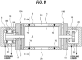
- FIG. 1 is a cross-sectional view showing an embodiment of a vacuum pump apparatus.
- the vacuum pump apparatus of the embodiment described below is a positive-displacement vacuum pump apparatus.
- the vacuum pump apparatus shown in FIG. 1 is a so-called dry vacuum pump apparatus that does not use oil in its flow passages for a gas. Since a vaporized oil does not flow to an upstream side, the dry vacuum pump apparatus can be suitably used for a semiconductor-device manufacturing apparatus that requires high cleanliness.
- the vacuum pump apparatus includes a pump casing 2 having a rotor chamber 1 therein, pump rotors 5 arranged in the rotor chamber 1, rotation shafts 7 to which the pump rotors 5 are fixed, and electric motor 8 coupled to the rotation shafts 7.
- Each pump rotor 5 and each rotation shaft 7 may be an integral structure. Although only one pump rotor 5 and only one rotation shaft 7 are depicted in FIG. 1 , a pair of pump rotors 5 are arranged in the rotor chamber 1, and are secured to a pair of rotation shafts 7, respectively.
- the electric motor 8 is coupled to one of the pair of rotation shafts 7. In one embodiment, a pair of electric motors 8 may be coupled to the pair of rotation shafts 7, respectively.
- the pump rotors 5 of the present embodiment are Roots-type pump rotors, while the type of the pump rotors 5 is not limited to the present embodiment.
- the pump rotors 5 may be screw-type pump rotors.
- the pump rotors 5 of the present embodiment are single-stage pump rotors, in one embodiment the pump rotors 5 may be multistage pump rotors.
- the vacuum pump apparatus further includes side covers 10A and 10B located outwardly of the pump casing 2 in an axial direction of the rotation shafts 7.
- the side covers 10A and 10B are provided on both sides of the pump casing 2 and are coupled to the pump casing 2.
- the side covers 10A and 10B are fixed to end surfaces of the pump casing 2 by not-shown screws.
- the rotor chamber 1 is formed by an inner surface of the pump casing 2 and inner surfaces of the side covers 10A and 10B.
- the pump casing 2 has an intake port 2a and an exhaust port 2b.
- the intake port 2a is coupled to a chamber (not shown) filled with gas to be delivered.
- the intake port 2a may be coupled to a process chamber of a semiconductor-device manufacturing apparatus, and the vacuum pump apparatus may be used for exhausting a process gas that has been introduced into the process chamber.
- the vacuum pump apparatus further includes a motor housing 14 and a gear housing 16 which are housing structures located outwardly of the side covers 10A and 10B in the axial direction of the rotation shafts 7.
- the side cover 10A is located between the pump casing 2 and the motor housing 14, and the side cover 10B is located between the pump casing 2 and the gear housing 16.
- Each rotation shaft 7 is rotatably supported by a bearing 17 held by the side cover 10A and a bearing 18 held by the side cover 10B.
- the motor housing 14 accommodates a motor rotor 8A and a motor stator 8B of the electric motor 8 therein.
- the motor housing 14 and the gear housing 16 are examples of the housing structure, and the housing structures are not limited to this embodiment.
- the housing structure may be a bearing housing that holds a bearing.
- a pair of gears 20 that mesh with each other are arranged inside the gear housing 16, a pair of gears 20 that mesh with each other are arranged.
- FIG. 1 only one gear 20 is depicted.
- the electric motor 8 is rotated by a not-shown motor driver, and one rotation shaft 7 to which the electric motor 8 is coupled rotates the other rotation shaft 7 to which the electric motor 8 is not coupled in an opposite direction via the gears 20.
- a pair of electric motors 8, which are coupled to the pair of rotation shafts 7, respectively, may be provided.
- the pair of electric motors 8 are synchronously rotated in opposite directions by a not-shown motor driver, so that the pair of rotation shafts 7 and the pair of pump rotors 5 are synchronously rotated in opposite directions.
- the role of the gears 20 is to prevent loss of the synchronous rotation of the pump rotors 5 due to a sudden external cause.
- a cooling channel 21 is provided in the motor housing 14.
- a cooling channel 22 is provided in the gear housing 16.
- the cooling channel 21 extends through an entire circumferential wall of the motor housing 14, and the cooling channel 22 extends through an entire circumferential wall of the gear housing 16.
- the cooling channel 21 and the cooling channel 22 are coupled to a not-shown cooling-liquid supply source. Cooling liquid is supplied from the cooling-liquid supply source to the cooling channel 21 and the cooling channel 22.
- the cooling liquid flowing through the cooling channel 21 cools the motor housing 14, so that the electric motor 8 and the bearings 17 arranged in the motor housing 14 can be cooled.
- the cooling liquid flowing through the cooling channel 22 cools the gear housing 16, so that the gears 20 and the bearings 18 arranged in the gear housing 16 can be cooled.
- Some of the process gases to be handled by the vacuum pump apparatus include by-product that is solidified as the temperature decreases.
- the process gas is compressed in the process of being transferred from the intake port 2a to the exhaust port 2b by the pump rotors 5. Therefore, an inside of the rotor chamber 1 becomes hot due to the heat of compression of the process gas.
- the side cover 10A is configured to reduce heat transfer from the pump casing 2 to the motor housing 14, and the side cover 10B is configured to reduce heat transfer from the pump casing 2 to the gear housing 16. Therefore, the side covers 10A and 10B can maintain the inside of the rotor chamber 1 at a high temperature. In particular, the side covers 10A and 10B can maintain the inside of the rotor chamber 1 at a high temperature while the motor housing 14 and the gear housing 16 is cooled with the cooling liquid flowing through the cooling channels 21 and 22.
- the pump casing 2 and the side covers 10A and 10B forming the rotor chamber 1 are made of cast iron.
- the side covers 10A and 10B may be made of a material having a lower thermal conductivity than that of the cast iron.
- the vacuum pump apparatus further includes cartridge heaters 70A and 70B disposed in the side covers 10A and 10B, respectively.
- the cartridge heaters 70A and 70B are removably attached to the side covers 10A and 10B, respectively. Details of configurations of the cartridge heaters 70A and 70B will be described later.
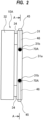
- FIG. 2 is a side view of the side cover 10A according to the embodiment shown in FIG. 1 .
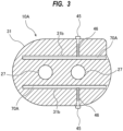
- FIG. 3 is a cross-sectional view taken along a line A-A of FIG. 2 .
- the side cover 10A has through-holes 27 through which the rotation shafts 7 extend. The through-holes 27 communicate with the rotor chamber 1.
- the side cover 10A has an inner wall portion 31 forming an end surface 31a of the rotor chamber 1, an outer wall portion 32 located outwardly of the inner wall portion 31 in the axial direction of the rotation shafts 7, and a plurality of spacers 34 sandwiched between the inner wall portion 31 and the outer wall portion 32.
- the inner wall portion 31 and the outer wall portion 32 are located away from each other by the spacers 34.
- the inner wall portion 31 is coupled to the pump casing 2 (see FIG. 1 ), and the outer wall portion 32 is coupled to the motor housing 14.
- the outer wall portion 32 has recesses (not shown) in which the bearings 17 are accommodated.
- a heat insulating material may be disposed between the outer wall portion 32 and the motor housing 14.
- the inner wall portion 31 of the side cover 10A has holes 31b opened in an outer surface of the side cover 10A (more specifically, an outer surface of the inner wall portion 31).
- the holes 31b extend linearly.
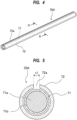
- Each cartridge heater 70A has a rod shape extending linearly, and is arranged in each hole 31b.
- the vacuum pump apparatus of this embodiment allows the cartridge heaters 70A to be locally mounted by providing the holes 31b at desired positions where the cartridge heaters 70A are to be attached.
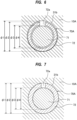
- the heater 71 may be heated up to about 600°C, which causes the heater 71 itself to thermally expand. When the heater 71 is repeatedly heated over a long period of operations, the entire heater 71 may be deformed. As a result, there is a problem that the heater 71 cannot be removed from the side cover 10A, and the heater 71 cannot be easily replaced when a malfunction of the cartridge heaters 70A occurs. If the inner diameter ⁇ 1 of the hole 31b of the inner wall portion 31 is enlarged in consideration of the deformation of the heater 71, the heat cannot be efficiently transferred from the heater 71 to the side cover 10A. As a result, power consumption of the heater 71 may increase, and operating cost may increase.
- the vacuum pump apparatus may further include the cartridge heaters 70A and 70B in the side covers 10A and 10B as well as the embodiments described with reference to FIGS. 1 to 7 , in addition to the cartridge heaters 70 in the pump casing 2 described above.
- the side cover 10A of this embodiment has an inner wall portion 31 forming an end surface 31a of the rotor chamber 1, an outer wall portion 32 located outwardly of the inner wall portion 31 in the axial direction of the rotation shafts 7, and the narrow portion 33 located between the inner wall portion 31 and the outer wall portion 32.
- the inner wall portion 31 is coupled to the pump casing 2 and the outer wall portion 32 is coupled to the motor housing 14.
- the outer wall portion 32 has recesses 32a in which the bearings 17 are accommodated.
- a heat insulating material may be disposed between the outer wall portion 32 and the motor housing 14.
- the inner wall portion 31, the outer wall portion 32, and the narrow portion 33 are an integral structure.
- the inner wall portion 31, the outer wall portion 32, and the narrow portion 33 are an integrally molded casting. Since the side cover 10A includes the integral structure, it is not necessary to produce multiple members separately and assemble these multiple members. As a result, manufacturing cost can be reduced.
- the side covers 10A and 10B having such narrow portions 33 have high heat insulating performances, the interior of the rotor chamber 1 can be maintained at a high temperature. Furthermore, cooling of the pump casing 2 by the cooling liquid flowing through the cooling channel 21 and the cooling channel 22 can be prevented.
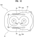
- the side cover 10A has two heater housings 35 having holes 35a, respectively.
- the two heater housings 35, the inner wall portion 31, the outer wall portion 32, and the narrow portion 33 are an integral structure.
- Each hole 35a is open in an outer surface of the side cover 10A (more specifically, an outer surface of the heater housing 35), and the cartridge heater 70A is arranged in the hole 35a.
- two cartridge heaters 70A are arranged so as to sandwich the rotation shafts 7. In one embodiment, only one cartridge heater 70A may be provided, or three or more cartridge heaters 70A may be provided.
- the holes 35a extend linearly, and the cartridge heaters 70A are rod-shaped heaters extending linearly. With the cartridge heaters 70A inserted into the holes 35a, the cartridge heaters 70A are fixed to the side cover 10A by screws 45, respectively, which are fixing mechanisms. More specifically, the heater housing 35 has screw holes 46 communicating with the holes 35a. When each screw 45 is screwed into each screw hole 46, a distal end of each screw 45 presses the cartridge heater 70A in the hole 35a against the heater housing 35, so that positions of the cartridge heaters 70A are fixed. When each of the screws 45 is loosened, the cartridge heaters 70A can be removed from the holes 35a.
- the cartridge heaters 70A can be removed from the side covers 10A without disassembling the vacuum pump apparatus. Therefore, if the cartridge heater 70A breaks down, the cartridge heater 70A can be easily replaced with a new cartridge heater.
- a relationship between an inner diameter of the hole 35a of the heater housing 35, an outer diameter and an inner diameter of the heater casing 72 of the cartridge heater 70A, and an outer diameter of the heater 71 of the present embodiment is the same as the relationship of the inner diameter ⁇ 1 of the hole 31b of the side cover 10A, the outer diameter ⁇ 2 and the inner diameter ⁇ 3 of the heater casing 72 of the cartridge heater 70A, and the outer diameter ⁇ 4 of the heater 71 described with reference to FIGS. 6 and 7 , and duplicated descriptions are omitted.
- the heater 71 When the heater 71 generates the heat, the heat is transferred through the heater casing 72 and transferred from the heater housings 35 and the inner wall portion 31 to the rotor chamber 1 (see FIG. 10 ), so that the rotor chamber 1 can be heated. As a result, the inside of the rotor chamber 1 can be maintained at a high temperature, and solidification of by-product contained in the process gas can be prevented. In particular, since the heater housings 35 and the inner wall portion 31 are integrally formed, heat conduction efficiency from the cartridge heaters 70A to the inner wall portion 31 is improved.
- each heater housing 35 is separated from the outer wall portion 32. Although not shown, the entire heater housings 35 may be located away from the outer wall portion 32. With such a configuration, the heat generated by the heaters 71 and transferred through the heater casings 72 is less likely to be transferred to the outer wall portion 32. Therefore, this configuration can prevent heating of the motor housing 14 (see FIG. 10 ), which is a housing structure coupled to the outer wall portion 32, while the cartridge heaters 70A heats the rotor chamber 1.
- the cartridge heater 70A includes the heater casing 72 covering the heater 71. Therefore, when the heater 71 generates the heat, the heater 71 and the heater casing 72 thermally expand. As a result, the gap between the heater 71 and the heater casing 72 becomes smaller. More specifically, the inner diameter of the heater casing 72 becomes equal to the outer diameter of the heater 71.
- the heater casing 72 having the slit 72a can absorb the deformation of the heater 71 over time. Therefore, deformation of the entire cartridge heater 70A due to the deformation of the heater 71 over time can be prevented, so that the cartridge heater 70A can be easily removed from the heater housing 35.
- the heater casing 72 which is made of the material having a higher coefficient of linear expansion than that of the outer shell 71b of the heater 71, thermally expands more greatly than the heater 71.
- the heater casing 72 expands until the heater casing 72 contacts the inner wall forming the hole 35a of the heater housing 35. More specifically, the outer diameter of the heater casing 72 becomes equal to the inner diameter of the hole 35a.
- the thermally-expanding heater casing 72 can fill the gap between the heater housing 35 (more specifically, the inner wall forming the hole 35a) and the heater 71. Therefore, the heat can be transferred efficiently from the cartridge heater 70A to the heater housing 35.
- the heater 71 and the heater casing 72 contract, so that the gap is formed again between the heater housing 35 (more specifically, the inner wall forming the hole 35a) and the heater casing 72. Therefore, the cartridge heater 70A can be easily attached to and removed from the heater housing 35.
- the cartridge heaters 70B are also disposed in the side cover 10B.
- the descriptions with reference to FIGS. 11 to 13 can also be applied to the side cover 10B and the cartridge heaters 70B disposed therein, and duplicated descriptions are omitted.
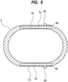
- the vacuum pump apparatus may further include the cartridge heaters 70 in the pump casing 2 as well as the embodiments described with reference to FIGS. 8 and 9 , in addition to the cartridge heaters 70A and 70B in the side covers 10A and 10B described above.
Landscapes
- Engineering & Computer Science (AREA)
- Mechanical Engineering (AREA)
- General Engineering & Computer Science (AREA)
- Applications Or Details Of Rotary Compressors (AREA)
Claims (5)
- Vakuumpumpenvorrichtung, umfassend:ein Pumpengehäuse (2) mit einer Rotorkammer (1) darin;einen Pumpenrotor (5), der in der Rotorkammer (1) angeordnet ist;eine Drehwelle (7), an welcher der Pumpenrotor (5) befestigt ist;einen Elektromotor (8), der mit der Drehwelle (7) gekoppelt ist;eine Seitenabdeckung (10A, 10B), die eine Endfläche der Rotorkammer (1) bildet; undeine Gehäusestruktur (14, 16), die außerhalb der Seitenabdeckung (10A, 10B) in einer axialen Richtung der Drehwelle (7) angeordnet ist;eine Patronenheizung (70A, 70B; 70), die in der Seitenabdeckung (10A, 10B) oder in dem Pumpengehäuse (2) angeordnet ist und abnehmbar an der Seitenabdeckung (10A, 10B) oder dem Pumpengehäuse (2) angebracht ist,wobei die Patronenheizung (70A, 70B; 70) eine Heizung (71) aufweist, dadurch gekennzeichnet, dass die Patronenheizung (70A, 70B; 70) ein Heizungsgehäuse (72) aufweist, das mindestens einen Teil der Heizung (71) abdeckt, unddas Heizungsgehäuse (72) einen Schlitz (72a) aufweist, der sich von einem Ende zu dem anderen Ende davon erstreckt.
- Vakuumpumpenvorrichtung nach Anspruch 1, wobei das Heizungsgehäuse (72) aus einem Material hergestellt ist, das einen höheren linearen Ausdehnungskoeffizienten aufweist als der eines Materials, das eine Außenhülle (71b) der Heizung (71) bildet.
- Vakuumpumpenvorrichtung nach Anspruch 2, wobei das Heizungsgehäuse (72) aus einer Aluminiumlegierung, Aluminium, Kupfer oder Magnesium hergestellt ist.
- Vakuumpumpenvorrichtung nach einem der Ansprüche 1 bis 3, wobeidie Seitenabdeckung (10A, 10B) oder das Pumpengehäuse (2) ein Loch aufweist, das in einer Außenfläche der Seitenabdeckung (10A, 10B) oder des Pumpengehäuses (2) offen ist, wobei sich das Loch linear erstreckt, unddie Patronenheizung (70A, 70B; 70) eine Stabform aufweist und in dem Loch angeordnet ist.
- Vakuumpumpenvorrichtung nach einem der Ansprüche 1 bis 4, ferner umfassend einen Befestigungsmechanismus (45), der konfiguriert ist, um die Patronenheizung (70A, 70B; 70) abnehmbar an der Seitenabdeckung (10A, 10B) oder dem Pumpengehäuse (2) zu befestigen.
Applications Claiming Priority (1)
| Application Number | Priority Date | Filing Date | Title |
|---|---|---|---|
| JP2021182249A JP7689060B2 (ja) | 2021-11-09 | 2021-11-09 | 真空ポンプ装置 |
Publications (2)
| Publication Number | Publication Date |
|---|---|
| EP4177465A1 EP4177465A1 (de) | 2023-05-10 |
| EP4177465B1 true EP4177465B1 (de) | 2025-01-22 |
Family
ID=84329498
Family Applications (1)
| Application Number | Title | Priority Date | Filing Date |
|---|---|---|---|
| EP22205764.8A Active EP4177465B1 (de) | 2021-11-09 | 2022-11-07 | Vakuumpumpenvorrichtung |
Country Status (5)
| Country | Link |
|---|---|
| EP (1) | EP4177465B1 (de) |
| JP (1) | JP7689060B2 (de) |
| KR (1) | KR20230068302A (de) |
| CN (1) | CN116104762A (de) |
| TW (1) | TW202331101A (de) |
Family Cites Families (8)
| Publication number | Priority date | Publication date | Assignee | Title |
|---|---|---|---|---|
| JP4017365B2 (ja) | 2001-07-19 | 2007-12-05 | 株式会社荏原製作所 | ドライ真空ポンプ |
| JP2007262906A (ja) | 2006-03-27 | 2007-10-11 | Nabtesco Corp | 2段式真空ポンプ |
| KR101926658B1 (ko) | 2017-03-15 | 2018-12-07 | 이인철 | 반도체 챔버용 펌프 시스템 |
| WO2019004089A1 (ja) | 2017-06-28 | 2019-01-03 | 京セラ株式会社 | ヒータ |
| CN110651124B (zh) | 2017-08-07 | 2021-03-05 | 株式会社爱发科 | 真空泵 |
| WO2020255300A1 (ja) | 2019-06-19 | 2020-12-24 | 樫山工業株式会社 | 真空ポンプ |
| JP7261139B2 (ja) | 2019-10-15 | 2023-04-19 | 株式会社荏原製作所 | 真空ポンプ装置 |
| JP2021063503A (ja) | 2019-10-15 | 2021-04-22 | 株式会社荏原製作所 | 真空ポンプ装置 |
-
2021
- 2021-11-09 JP JP2021182249A patent/JP7689060B2/ja active Active
-
2022
- 2022-10-27 KR KR1020220139940A patent/KR20230068302A/ko active Pending
- 2022-11-07 CN CN202211386301.3A patent/CN116104762A/zh active Pending
- 2022-11-07 EP EP22205764.8A patent/EP4177465B1/de active Active
- 2022-11-07 TW TW111142439A patent/TW202331101A/zh unknown
Also Published As
| Publication number | Publication date |
|---|---|
| TW202331101A (zh) | 2023-08-01 |
| EP4177465A1 (de) | 2023-05-10 |
| CN116104762A (zh) | 2023-05-12 |
| KR20230068302A (ko) | 2023-05-17 |
| JP2023070219A (ja) | 2023-05-19 |
| JP7689060B2 (ja) | 2025-06-05 |
Similar Documents
| Publication | Publication Date | Title |
|---|---|---|
| EP3808982B1 (de) | Vakuumpumpe mit thermischer isolierung | |
| JP2021063503A (ja) | 真空ポンプ装置 | |
| KR101760549B1 (ko) | 진공 펌프 | |
| EP2378122B1 (de) | Trockenvakuumpumpenvorrichtung und Kühlverfahren dafür | |
| KR102437094B1 (ko) | 냉각스크린 및 냉각장치가 구비된 스크류형 진공펌프 | |
| CN110863997A (zh) | 带内加热装置的磁悬浮分子泵 | |
| EP4177465B1 (de) | Vakuumpumpenvorrichtung | |
| EP4067658B1 (de) | Vakuumpumpengerät | |
| EP3808983B1 (de) | Vakuumpumpe mit heizung im seitendeckel | |
| JPWO2003098047A1 (ja) | 真空ポンプ | |
| JP2968188B2 (ja) | 真空ポンプ装置 | |
| EP4198315A1 (de) | Vakuumpumpenvorrichtung und verfahren zum betrieb davon | |
| JPH1162880A (ja) | ターボ分子ポンプ | |
| JP7606002B2 (ja) | ロータリー容積移送式ポンプ | |
| WO2025107070A1 (en) | Motor assembly with thermal ground plate | |
| JP2015004326A (ja) | 真空ポンプ装置 | |
| KR20090048359A (ko) | 펌핑 유닛 및 대응하는 가열 장치 | |
| CN120380255A (zh) | 真空泵 | |
| JP2023089930A (ja) | 真空ポンプ装置およびその運転方法 |
Legal Events
| Date | Code | Title | Description |
|---|---|---|---|
| PUAI | Public reference made under article 153(3) epc to a published international application that has entered the european phase |
Free format text: ORIGINAL CODE: 0009012 |
|
| STAA | Information on the status of an ep patent application or granted ep patent |
Free format text: STATUS: THE APPLICATION HAS BEEN PUBLISHED |
|
| AK | Designated contracting states |
Kind code of ref document: A1 Designated state(s): AL AT BE BG CH CY CZ DE DK EE ES FI FR GB GR HR HU IE IS IT LI LT LU LV MC ME MK MT NL NO PL PT RO RS SE SI SK SM TR |
|
| RAP3 | Party data changed (applicant data changed or rights of an application transferred) |
Owner name: EBARA CORPORATION |
|
| STAA | Information on the status of an ep patent application or granted ep patent |
Free format text: STATUS: REQUEST FOR EXAMINATION WAS MADE |
|
| 17P | Request for examination filed |
Effective date: 20231107 |
|
| RBV | Designated contracting states (corrected) |
Designated state(s): AL AT BE BG CH CY CZ DE DK EE ES FI FR GB GR HR HU IE IS IT LI LT LU LV MC ME MK MT NL NO PL PT RO RS SE SI SK SM TR |
|
| GRAP | Despatch of communication of intention to grant a patent |
Free format text: ORIGINAL CODE: EPIDOSNIGR1 |
|
| STAA | Information on the status of an ep patent application or granted ep patent |
Free format text: STATUS: GRANT OF PATENT IS INTENDED |
|
| INTG | Intention to grant announced |
Effective date: 20240828 |
|
| GRAS | Grant fee paid |
Free format text: ORIGINAL CODE: EPIDOSNIGR3 |
|
| GRAA | (expected) grant |
Free format text: ORIGINAL CODE: 0009210 |
|
| STAA | Information on the status of an ep patent application or granted ep patent |
Free format text: STATUS: THE PATENT HAS BEEN GRANTED |
|
| P01 | Opt-out of the competence of the unified patent court (upc) registered |
Free format text: CASE NUMBER: APP_64773/2024 Effective date: 20241206 |
|
| AK | Designated contracting states |
Kind code of ref document: B1 Designated state(s): AL AT BE BG CH CY CZ DE DK EE ES FI FR GB GR HR HU IE IS IT LI LT LU LV MC ME MK MT NL NO PL PT RO RS SE SI SK SM TR |
|
| REG | Reference to a national code |
Ref country code: GB Ref legal event code: FG4D |
|
| REG | Reference to a national code |
Ref country code: CH Ref legal event code: EP |
|
| REG | Reference to a national code |
Ref country code: IE Ref legal event code: FG4D |
|
| REG | Reference to a national code |
Ref country code: DE Ref legal event code: R096 Ref document number: 602022009777 Country of ref document: DE |
|
| REG | Reference to a national code |
Ref country code: NL Ref legal event code: MP Effective date: 20250122 |
|
| PG25 | Lapsed in a contracting state [announced via postgrant information from national office to epo] |
Ref country code: NL Free format text: LAPSE BECAUSE OF FAILURE TO SUBMIT A TRANSLATION OF THE DESCRIPTION OR TO PAY THE FEE WITHIN THE PRESCRIBED TIME-LIMIT Effective date: 20250122 |
|
| PG25 | Lapsed in a contracting state [announced via postgrant information from national office to epo] |
Ref country code: RS Free format text: LAPSE BECAUSE OF FAILURE TO SUBMIT A TRANSLATION OF THE DESCRIPTION OR TO PAY THE FEE WITHIN THE PRESCRIBED TIME-LIMIT Effective date: 20250422 |
|
| PG25 | Lapsed in a contracting state [announced via postgrant information from national office to epo] |
Ref country code: FI Free format text: LAPSE BECAUSE OF FAILURE TO SUBMIT A TRANSLATION OF THE DESCRIPTION OR TO PAY THE FEE WITHIN THE PRESCRIBED TIME-LIMIT Effective date: 20250122 |
|
| PG25 | Lapsed in a contracting state [announced via postgrant information from national office to epo] |
Ref country code: PL Free format text: LAPSE BECAUSE OF FAILURE TO SUBMIT A TRANSLATION OF THE DESCRIPTION OR TO PAY THE FEE WITHIN THE PRESCRIBED TIME-LIMIT Effective date: 20250122 |
|
| PG25 | Lapsed in a contracting state [announced via postgrant information from national office to epo] |
Ref country code: ES Free format text: LAPSE BECAUSE OF FAILURE TO SUBMIT A TRANSLATION OF THE DESCRIPTION OR TO PAY THE FEE WITHIN THE PRESCRIBED TIME-LIMIT Effective date: 20250122 |
|
| REG | Reference to a national code |
Ref country code: LT Ref legal event code: MG9D |
|
| PG25 | Lapsed in a contracting state [announced via postgrant information from national office to epo] |
Ref country code: NO Free format text: LAPSE BECAUSE OF FAILURE TO SUBMIT A TRANSLATION OF THE DESCRIPTION OR TO PAY THE FEE WITHIN THE PRESCRIBED TIME-LIMIT Effective date: 20250422 Ref country code: IS Free format text: LAPSE BECAUSE OF FAILURE TO SUBMIT A TRANSLATION OF THE DESCRIPTION OR TO PAY THE FEE WITHIN THE PRESCRIBED TIME-LIMIT Effective date: 20250522 |
|
| REG | Reference to a national code |
Ref country code: AT Ref legal event code: MK05 Ref document number: 1761645 Country of ref document: AT Kind code of ref document: T Effective date: 20250122 |
|
| PG25 | Lapsed in a contracting state [announced via postgrant information from national office to epo] |
Ref country code: HR Free format text: LAPSE BECAUSE OF FAILURE TO SUBMIT A TRANSLATION OF THE DESCRIPTION OR TO PAY THE FEE WITHIN THE PRESCRIBED TIME-LIMIT Effective date: 20250122 |
|
| PG25 | Lapsed in a contracting state [announced via postgrant information from national office to epo] |
Ref country code: LV Free format text: LAPSE BECAUSE OF FAILURE TO SUBMIT A TRANSLATION OF THE DESCRIPTION OR TO PAY THE FEE WITHIN THE PRESCRIBED TIME-LIMIT Effective date: 20250122 Ref country code: PT Free format text: LAPSE BECAUSE OF FAILURE TO SUBMIT A TRANSLATION OF THE DESCRIPTION OR TO PAY THE FEE WITHIN THE PRESCRIBED TIME-LIMIT Effective date: 20250522 |
|
| PG25 | Lapsed in a contracting state [announced via postgrant information from national office to epo] |
Ref country code: BG Free format text: LAPSE BECAUSE OF FAILURE TO SUBMIT A TRANSLATION OF THE DESCRIPTION OR TO PAY THE FEE WITHIN THE PRESCRIBED TIME-LIMIT Effective date: 20250122 Ref country code: GR Free format text: LAPSE BECAUSE OF FAILURE TO SUBMIT A TRANSLATION OF THE DESCRIPTION OR TO PAY THE FEE WITHIN THE PRESCRIBED TIME-LIMIT Effective date: 20250423 |
|
| PG25 | Lapsed in a contracting state [announced via postgrant information from national office to epo] |
Ref country code: AT Free format text: LAPSE BECAUSE OF FAILURE TO SUBMIT A TRANSLATION OF THE DESCRIPTION OR TO PAY THE FEE WITHIN THE PRESCRIBED TIME-LIMIT Effective date: 20250122 |
|
| PG25 | Lapsed in a contracting state [announced via postgrant information from national office to epo] |
Ref country code: SE Free format text: LAPSE BECAUSE OF FAILURE TO SUBMIT A TRANSLATION OF THE DESCRIPTION OR TO PAY THE FEE WITHIN THE PRESCRIBED TIME-LIMIT Effective date: 20250122 |
|
| PG25 | Lapsed in a contracting state [announced via postgrant information from national office to epo] |
Ref country code: SM Free format text: LAPSE BECAUSE OF FAILURE TO SUBMIT A TRANSLATION OF THE DESCRIPTION OR TO PAY THE FEE WITHIN THE PRESCRIBED TIME-LIMIT Effective date: 20250122 |
|
| PG25 | Lapsed in a contracting state [announced via postgrant information from national office to epo] |
Ref country code: DK Free format text: LAPSE BECAUSE OF FAILURE TO SUBMIT A TRANSLATION OF THE DESCRIPTION OR TO PAY THE FEE WITHIN THE PRESCRIBED TIME-LIMIT Effective date: 20250122 |
|
| PG25 | Lapsed in a contracting state [announced via postgrant information from national office to epo] |
Ref country code: IT Free format text: LAPSE BECAUSE OF FAILURE TO SUBMIT A TRANSLATION OF THE DESCRIPTION OR TO PAY THE FEE WITHIN THE PRESCRIBED TIME-LIMIT Effective date: 20250122 |
|
| PG25 | Lapsed in a contracting state [announced via postgrant information from national office to epo] |
Ref country code: EE Free format text: LAPSE BECAUSE OF FAILURE TO SUBMIT A TRANSLATION OF THE DESCRIPTION OR TO PAY THE FEE WITHIN THE PRESCRIBED TIME-LIMIT Effective date: 20250122 |
|
| REG | Reference to a national code |
Ref country code: DE Ref legal event code: R097 Ref document number: 602022009777 Country of ref document: DE |
|
| PG25 | Lapsed in a contracting state [announced via postgrant information from national office to epo] |
Ref country code: RO Free format text: LAPSE BECAUSE OF FAILURE TO SUBMIT A TRANSLATION OF THE DESCRIPTION OR TO PAY THE FEE WITHIN THE PRESCRIBED TIME-LIMIT Effective date: 20250122 |
|
| PG25 | Lapsed in a contracting state [announced via postgrant information from national office to epo] |
Ref country code: SK Free format text: LAPSE BECAUSE OF FAILURE TO SUBMIT A TRANSLATION OF THE DESCRIPTION OR TO PAY THE FEE WITHIN THE PRESCRIBED TIME-LIMIT Effective date: 20250122 |
|
| PLBE | No opposition filed within time limit |
Free format text: ORIGINAL CODE: 0009261 |
|
| STAA | Information on the status of an ep patent application or granted ep patent |
Free format text: STATUS: NO OPPOSITION FILED WITHIN TIME LIMIT |