EP4060966B1 - Vorrichtung mit zusammenklappbarem bildschirm - Google Patents
Vorrichtung mit zusammenklappbarem bildschirm Download PDFInfo
- Publication number
- EP4060966B1 EP4060966B1 EP20904028.6A EP20904028A EP4060966B1 EP 4060966 B1 EP4060966 B1 EP 4060966B1 EP 20904028 A EP20904028 A EP 20904028A EP 4060966 B1 EP4060966 B1 EP 4060966B1
- Authority
- EP
- European Patent Office
- Prior art keywords
- electrical connection
- shaft cover
- connection line
- screen device
- positioning
- Prior art date
- Legal status (The legal status is an assumption and is not a legal conclusion. Google has not performed a legal analysis and makes no representation as to the accuracy of the status listed.)
- Active
Links
Images







Classifications
-
- H—ELECTRICITY
- H04—ELECTRIC COMMUNICATION TECHNIQUE
- H04M—TELEPHONIC COMMUNICATION
- H04M1/00—Substation equipment, e.g. for use by subscribers
- H04M1/02—Constructional features of telephone sets
- H04M1/0202—Portable telephone sets, e.g. cordless phones, mobile phones or bar type handsets
- H04M1/0206—Portable telephones comprising a plurality of mechanically joined movable body parts, e.g. hinged housings
- H04M1/0208—Portable telephones comprising a plurality of mechanically joined movable body parts, e.g. hinged housings characterized by the relative motions of the body parts
- H04M1/0214—Foldable telephones, i.e. with body parts pivoting to an open position around an axis parallel to the plane they define in closed position
-
- G—PHYSICS
- G06—COMPUTING OR CALCULATING; COUNTING
- G06F—ELECTRIC DIGITAL DATA PROCESSING
- G06F1/00—Details not covered by groups G06F3/00 - G06F13/00 and G06F21/00
- G06F1/16—Constructional details or arrangements
- G06F1/1613—Constructional details or arrangements for portable computers
- G06F1/1633—Constructional details or arrangements of portable computers not specific to the type of enclosures covered by groups G06F1/1615 - G06F1/1626
- G06F1/1675—Miscellaneous details related to the relative movement between the different enclosures or enclosure parts
- G06F1/1683—Miscellaneous details related to the relative movement between the different enclosures or enclosure parts for the transmission of signal or power between the different housings, e.g. details of wired or wireless communication, passage of cabling
-
- H—ELECTRICITY
- H04—ELECTRIC COMMUNICATION TECHNIQUE
- H04M—TELEPHONIC COMMUNICATION
- H04M1/00—Substation equipment, e.g. for use by subscribers
- H04M1/02—Constructional features of telephone sets
- H04M1/0202—Portable telephone sets, e.g. cordless phones, mobile phones or bar type handsets
- H04M1/0206—Portable telephones comprising a plurality of mechanically joined movable body parts, e.g. hinged housings
- H04M1/0208—Portable telephones comprising a plurality of mechanically joined movable body parts, e.g. hinged housings characterized by the relative motions of the body parts
- H04M1/0214—Foldable telephones, i.e. with body parts pivoting to an open position around an axis parallel to the plane they define in closed position
- H04M1/0216—Foldable in one direction, i.e. using a one degree of freedom hinge
- H04M1/022—The hinge comprising two parallel pivoting axes
-
- H—ELECTRICITY
- H04—ELECTRIC COMMUNICATION TECHNIQUE
- H04M—TELEPHONIC COMMUNICATION
- H04M1/00—Substation equipment, e.g. for use by subscribers
- H04M1/02—Constructional features of telephone sets
- H04M1/0202—Portable telephone sets, e.g. cordless phones, mobile phones or bar type handsets
- H04M1/026—Details of the structure or mounting of specific components
- H04M1/0266—Details of the structure or mounting of specific components for a display module assembly
- H04M1/0268—Details of the structure or mounting of specific components for a display module assembly including a flexible display panel
-
- H—ELECTRICITY
- H04—ELECTRIC COMMUNICATION TECHNIQUE
- H04M—TELEPHONIC COMMUNICATION
- H04M1/00—Substation equipment, e.g. for use by subscribers
- H04M1/02—Constructional features of telephone sets
- H04M1/0202—Portable telephone sets, e.g. cordless phones, mobile phones or bar type handsets
- H04M1/026—Details of the structure or mounting of specific components
- H04M1/0274—Details of the structure or mounting of specific components for an electrical connector module
-
- H—ELECTRICITY
- H04—ELECTRIC COMMUNICATION TECHNIQUE
- H04M—TELEPHONIC COMMUNICATION
- H04M1/00—Substation equipment, e.g. for use by subscribers
- H04M1/02—Constructional features of telephone sets
- H04M1/0202—Portable telephone sets, e.g. cordless phones, mobile phones or bar type handsets
- H04M1/026—Details of the structure or mounting of specific components
- H04M1/0277—Details of the structure or mounting of specific components for a printed circuit board assembly
-
- H—ELECTRICITY
- H04—ELECTRIC COMMUNICATION TECHNIQUE
- H04M—TELEPHONIC COMMUNICATION
- H04M1/00—Substation equipment, e.g. for use by subscribers
- H04M1/02—Constructional features of telephone sets
- H04M1/18—Telephone sets specially adapted for use in ships, mines, or other places exposed to adverse environment
- H04M1/185—Improving the shock resistance of the housing, e.g. by increasing the rigidity
-
- H—ELECTRICITY
- H05—ELECTRIC TECHNIQUES NOT OTHERWISE PROVIDED FOR
- H05K—PRINTED CIRCUITS; CASINGS OR CONSTRUCTIONAL DETAILS OF ELECTRIC APPARATUS; MANUFACTURE OF ASSEMBLAGES OF ELECTRICAL COMPONENTS
- H05K1/00—Printed circuits
- H05K1/02—Details
- H05K1/0277—Bendability or stretchability details
- H05K1/028—Bending or folding regions of flexible printed circuits
-
- H—ELECTRICITY
- H05—ELECTRIC TECHNIQUES NOT OTHERWISE PROVIDED FOR
- H05K—PRINTED CIRCUITS; CASINGS OR CONSTRUCTIONAL DETAILS OF ELECTRIC APPARATUS; MANUFACTURE OF ASSEMBLAGES OF ELECTRICAL COMPONENTS
- H05K1/00—Printed circuits
- H05K1/18—Printed circuits structurally associated with non-printed electric components
- H05K1/189—Printed circuits structurally associated with non-printed electric components characterised by the use of flexible or folded printed circuits
-
- H—ELECTRICITY
- H05—ELECTRIC TECHNIQUES NOT OTHERWISE PROVIDED FOR
- H05K—PRINTED CIRCUITS; CASINGS OR CONSTRUCTIONAL DETAILS OF ELECTRIC APPARATUS; MANUFACTURE OF ASSEMBLAGES OF ELECTRICAL COMPONENTS
- H05K2201/00—Indexing scheme relating to printed circuits covered by H05K1/00
- H05K2201/10—Details of components or other objects attached to or integrated in a printed circuit board
- H05K2201/10007—Types of components
- H05K2201/10128—Display
Definitions
- This application relates to the field of terminal devices, and in particular, to a foldable screen device.
- the mobile phone may use a foldable structure.
- the mobile phone may usually have two main bodies that can relatively rotate around a rotating shaft and can be folded, and a flexible screen body of a screen covers both surfaces of the two main bodies of the mobile phone.
- the screen When the two bodies rotate around the rotating shaft between the bodies to be in a same plane, the screen is in an unfolded state and has a relatively large display area.
- the mobile phone When the two bodies rotate around the rotating shaft to be relatively folded, the mobile phone has a relatively small volume and size.
- Electronic components such as circuit boards are disposed in the two main bodies. An electrical connection between the electronic components in the different main bodies is implemented through a flexible electrical connection line that crosses two sides of the rotating shaft.
- US 2018/324964 A1 discloses an electronic device including a first housing and a second housing, wherein a hinge structure may be disposed between the first housing and the second housing. Further, a flexible printed circuit board may be disposed across the first housing and the second housing. For example, the flexible printed circuit board may extend from the first housing through the hinge structure to the second housing.
- US 2019/320048 A1 discloses a mobile terminal having first to third bodies, wherein first to third magnet portions are disposed in a section needed to be fixed and coupled in the body part of the mobile terminal so that the first to third bodies are coupled in a fixed state when they are aligned in a row or overlap one another.
- the first magnet portion may be disposed on a button portion that can be pressed by an external force and the second and third magnet portions may be disposed respectively on end portions of the second and third bodies, respectively.
- this application provides a foldable screen device, including two frames, a rotating shaft assembly articulated with the two frames, and an electrical connection line.
- the two frames are capable of rotating around rotating shafts of the rotating shaft assembly to be closed or opened.
- the rotating shaft assembly includes a connection structure and hinges.
- the hinge is connected between the connection structure and the frame, the connection structure has channels passing through two opposite sides of the rotating shaft assembly, two ends of the electrical connection line are respectively connected to the two frames, the electrical connection line penetrates into the channel, and the channel and the hinge are located at different positions of the rotating shaft assembly in an axial direction.
- the electrical connection line is positioned by the rotating shaft assembly, so that bending deformation generated by the electrical connection line when the foldable screen device is folded is relatively small, and a bending amount is prone to control. Therefore, connection reliability is high.
- connection structure is located in a middle region of the rotating shaft assembly in an axial direction.
- a region in which the connection structure is located may form a static accommodation space, and the electrical connection line positioned by the connection structure may pass through and be accommodated in the region, and is not interfered by a structure such as the rotating shaft during rotation.
- connection structure includes a first shaft cover and a second shaft cover, the first shaft cover and the second shaft cover are disposed opposite to each other, the first shaft cover is located on a side that is of the rotating shaft assembly and that is close to articulated ends of the frames, the second shaft cover is located on a side that is of the rotating shaft assembly and that is close to free ends of the frames, and the first shaft cover and the second shaft cover enclose a space that can accommodate the rotating shafts.
- the first shaft cover and the second shaft cover jointly form the accommodation space, and the electrical connection line is accommodated inside the accommodation space. Therefore, the electrical connection line is shielded and protected by the first shaft cover and the second shaft cover. In this way, structure reliability is relatively high, and appearance is relatively good.
- connection structure further includes a positioning piece, the positioning piece is located in the space jointly enclosed by the first shaft cover and the second shaft cover, and the channel is jointly formed by the positioning piece and one of the first shaft cover and the second shaft cover.
- the positioning piece and the first shaft cover or the second shaft cover jointly form a positioning point located at the middle segment of the electrical connection line, and positions of the middle segment and end parts of the electrical connection line are all positioned, so that a length of a part that can be freely bent and that is of the electrical connection line is reduced, and correspondingly, a bending deformation amplitude is also reduced.
- the entire electrical connection line is divided into two segments with similar lengths in a length direction, bending deformation amounts of the two segments of the electric connection line are relatively similar, and deformation and displacement of the two segments are relatively synchronous. In this way, the electrical connection line positioned with the aid of the rotating shaft assembly generates small bending deformation when the foldable screen device is folded, and a bending amount is prone to control. Therefore, connection reliability is high.
- the positioning piece and the first shaft cover jointly enclose the channel.
- the foldable screen device further includes a first magnetic piece and a second magnetic piece.
- the first magnetic piece is disposed on the first shaft cover
- the second magnetic piece is disposed on the positioning piece
- the first magnetic piece and the second magnetic piece are attractable to each other, so that the positioning piece and the first shaft cover are positioned to each other.
- the electrical connection line may be disposed on an assembly component in advance in an assembly process of the rotating shaft assembly, to prevent the electrical connection line from being detached from an assembly position due to external pulling or other forces, and effectively reduce assembly difficulty.
- the first shaft cover and the positioning piece can clamp tightly, or the electrical connection line can be attached to the first shaft cover, to assist in positioning the electrical connection line.
- both the first magnetic piece and the second magnetic piece are magnets.
- one of the first magnetic piece and the second magnetic piece is a magnet, and the other is a soft magnet. In this way, the first magnetic piece and the second magnetic piece are disposed in a relatively free manner, and structures are relatively simple.
- the electrical connection line includes a flexible printed circuit board.
- the flexible printed circuit board includes a plurality of leads, so that transmission of a plurality of different electrical signals can be implemented.
- the electrical connection line further includes a cable, and the flexible printed circuit board and the cable are spaced apart and disposed side by side.
- the cable may be configured to transmit different signals such as a coaxial signal, and the cable and the flexible printed circuit board are disposed relatively independently without interference or mutual impact.
- a guide groove is provided on the second fixing surface of the positioning piece, the guide groove passes through two opposite sides in a width direction of the positioning piece, a groove opening of the guide groove faces the first shaft cover, and the cable penetrates into the guide groove.
- a cable segment that is of the cable and that is located between the positioning piece and the first shaft cover may be partially or all buried in the guide groove, to be positioned.
- the foldable screen device further includes a flexible protective cover. Edges of two opposite sides of the flexible protective cover are respectively connected to the two frames, and the flexible protective cover covers a side that is of the electrical connection line and that faces the free end of the frame. When the foldable screen device is opened and closed, the flexible protective cover is blocked between the electrical connection line and an outer structure, to prevent the outer structure from contacting the electrical connection line.
- the flexible protective cover has a corrugated cover body.
- the entire flexible protective cover has an uneven corrugated surface, and the corrugated surface may be correspondingly unfolded or folded when the foldable screen device is opened or closed, to form protection regions of different sizes to adapt to different opening and closing angles of the foldable screen device.
- the flexible protective cover is made of a thermally conductive material.
- the flexible protective cover connected between the different frames can transfer heat on a frame to another frame, so that temperatures of the two frames are relatively uniform.
- a temperature difference between parts that are of the flexible screen and that are correspondingly disposed on different frames is relatively small, and display uniformity is relatively good.
- the flexible protective cover has a heat dissipation surface that is attached to a surface of the frame.
- the heat dissipation surface has a relatively large heat dissipation area. Therefore, the flexible protective cover can implement a relatively fast heat conduction speed by using the heat dissipation surface and the frame, so that there is relatively good temperature uniformity between the first frame and the second frame.
- the foldable screen device includes a first frame, a second frame, and the rotating shaft assembly connected between the first frame and the second frame.
- the connection structure in the rotating shaft assembly forms a channel through which an electrical connection line can pass and that can fasten the electrical connection line.
- the electrical connection line is positioned by the rotating shaft assembly, and therefore, a length of a part that can be freely bent and that is of the electrical connection line is reduced, and correspondingly, a bending deformation amplitude is also reduced.
- the entire electrical connection line is divided into two segments with similar lengths in a length direction, bending deformation amounts of the two segments of the electric connection line are relatively similar, and deformation and displacement of the two segments are relatively synchronous. In this way, the electrical connection line positioned with the aid of the rotating shaft assembly generates small bending deformation when the foldable screen device is folded, and a bending amount is prone to control. Therefore, connection reliability is high
- a terminal device such as a mobile phone may implement screen bending and folding by using the flexible screen, so that the terminal device has a relatively compact size, and the flexible screen has a relatively large display area.
- the terminal device may be a foldable screen device or a curved screen device.
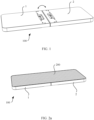
- FIG. 1 is a schematic diagram of a structure of a foldable screen device according to an embodiment of this application.
- FIG. 2a is a schematic diagram of a structure of the foldable screen device in FIG. 1 in an unfolded state.
- FIG. 2b is a schematic diagram of a structure of the foldable screen device in FIG. 1 in a folded state.
- a foldable screen device 100 includes two frames and a flexible screen 200 disposed on these frames.
- the foldable screen device 100 may correspondingly present different states such as a folded state or an unfolded state.
- the flexible screen 200 covers surfaces of the frames, and may accordingly present a folded state, an unfolded state, or the like as positions of the adjacent frames change.
- the foldable screen device 100 includes a first frame 1 and a second frame 2. When the first frame 1 and the second frame 2 are unfolded, the first frame 1 and the second frame 2 are disposed side by side and on a same plane.
- a relatively large display surface may be formed, and the display surface may serve as an independent screen for displaying, as shown in FIG. 2a .
- a quantity of frames of the foldable screen device 100 may be two or more. When there are more than two frames, adjacent frames may rotate around rotating shafts parallel to each other, to form a multi-layer folded structure or be unfolded to form a larger display area. In this application, an example in which the foldable screen device 100 has two frames is mainly used for description.
- a rotating shaft located between two adjacent frames may be a physical rotating shaft, or may be a virtual rotating shaft.
- the rotating shaft is not completely formed by physical components of the foldable screen device, but is a virtual rotating line formed by using shape constraints and displacement constraints of different components of the foldable screen device during relative movement.
- the two adjacent frames of the foldable screen device relatively rotate around the virtual rotating shaft during relative movement.
- Components such as a primary circuit board, a processor, a memory, and a camera assembly inside the foldable screen device may be separately fastened to the first frame 1 or the second frame 2.
- the components such as the primary circuit board, the processor, and the memory may be disposed inside the first frame 1, and the second frame 2 may be configured to carry the components such as the camera assembly and an antenna.
- an electrical connection line is further disposed in the foldable screen device. Two ends of the electrical connection line are respectively connected to electrical connection points of the two adjacent different frames, to be connected to the different components such as the primary circuit board, the processor, the camera assembly, or the antenna in the frames and transmit an electrical signal.
- the electrical connection line is made of a flexible material, and may be accordingly bent or deformed as relative positions of the frames change. In this way, when the foldable screen device is in different states such as a folded state or an unfolded state, the electrical connection line can still maintain the electrical connection between the two adjacent frames depending on bending deformation of the electrical connection line.
- the electrical connection line may have a plurality of different structures and forms.
- the primary circuit board in the foldable screen device may be located in one of the frames, and the primary circuit board transmits an electrical signal to a plurality of other components.
- the electrical connection line includes a flexible printed circuit board (FPC).
- the flexible printed circuit board may include a plurality of leads, so that transmission of a plurality of different electrical signals can be implemented.
- the components such as the antenna in the foldable screen device may be electrically connected to the primary circuit board by using a coaxial cable. Therefore, in an optional manner, the electrical connection line may also include a single independently disposed cable, and the cable may be configured to implement signal transmission between two independent components. In this embodiment, a single cable may be configured to transmit different signals such as a coaxial signal.
- the foldable screen device needs to have a relatively large unfolding and folding angle.
- an angle formed between the two frames of the foldable screen device may change between 0° and 180°.
- a spacing between two ends of the electrical connection line also changes in a relatively large range. Therefore, when the flexible screen is folded, a relatively long redundant length needs to be reserved for the electrical connection line, to adapt to the spacing between the electrical connection points on the two frames when the flexible screen is unfolded.
- the redundant length of the electrical connection line is excessively long, the electrical connection line is only in a large-angle bending state in a region between the two frames, and then can be normally accommodated between the two frames.
- the electrical connection line may be in a different bending state.
- the electrical connection line switches between a large-angle bending state and an extended state, and the electrical connection line is prone to break or fail due to material fatigue.
- the electrical connection line is bent at a large angle between the frames, the electrical connection line is prone to generate friction or scratch with another component inside the foldable screen device, to cause damage to a surface of the electrical connection line.
- this application provides a foldable screen device, so that a screen can be folded or unfolded through relative rotation of frames.
- an electrical connection line used to maintain an electrical connection between adjacent frames has relatively high reliability, and is not prone to break or wear.
- FIG. 3 is a schematic exploded view of main components of the foldable screen device in FIG. 1 .
- a physical folded structure of the foldable screen device mainly includes a first frame 1, a second frame 2, and a rotating shaft assembly 3 connected between the first frame 1 and the second frame 2.
- One end that is of each of the two frames and that is connected to the rotating shaft assembly 3 serves as an articulated end, and one end that is of the frame and that is away from the rotating shaft assembly 3 serves as a free end.
- the free ends of the two frames may rotate around the rotating shaft assembly 3, so that an overall structure of the foldable screen device is in an opened or closed state.
- FIG. 4 is a schematic exploded view of the rotating shaft assembly of the foldable screen device according to this application.
- the rotating shaft assembly shown in FIG. 4 includes a connection structure 31 and two hinges 32 connected to the connection structure 31.
- Each hinge 32 includes two rotating shafts 321 disposed in parallel and a plurality of articulated arms 322 correspondingly connected to the rotating shafts 321.
- One end of the articulated arm 322 is articulated to the rotating shaft, and the other end of the articulated arm 322 is configured to be fixedly connected to a corresponding frame.
- the first frame 1 and the second frame 2 may respectively rotate around the corresponding rotating shafts 321.
- the two rotating shafts 321 are disposed in parallel, and different frames are correspondingly connected to different rotating shafts 321, so that the two frames of the foldable screen device can be folded and unfolded at relatively large angles.
- the hinge 32 further includes a support 323.
- the support 323 supports and is disposed between the connection structure 31 and the rotating shaft 321, and the rotating shaft 321 can freely rotate relative to the support 323.
- the support 323 may be in a form of a support rib.
- an overall structure of the rotating shaft assembly 3 may further have a plurality of different shapes and types. For a specific shape of the rotating shaft assembly 3, refer to a rotating shaft support structure commonly used by a person skilled in the art. Details are not described herein.
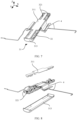
- FIG. 5a is a schematic diagram of a position of the rotating shaft assembly when the foldable screen device in FIG. 1 is in an unfolded state.
- FIG. 5b is a schematic diagram of a position of the rotating shaft assembly when the foldable screen device in FIG. 1 is in a folded state.
- FIG. 5a and FIG. 5b it can be easily seen that, when the rotating shaft assembly 3 is connected to the first frame 1 and the second frame 2, and a closing or opening operation is performed, the first frame 1 and the second frame 2 respectively rotate around the two rotating shafts 321 inside the rotating shaft assembly 3.
- the overall structure of the rotating shaft assembly 3 does not undergo folding or other deformation, that is, the entire rotating shaft assembly 3 undergoes only a posture change, and does not undergo deformation such as folding.
- Components other than the rotating shafts 321 inside the rotating shaft assembly 3 do not generate relative rotation or other relative displacement. Therefore, the rotating shaft assembly 3 may serve as a whole, and an internal structure of the rotating shaft assembly 3 is used to assist in positioning and fixing the electrical connection line 4 or another component.
- the two hinges 32 in the rotating shaft assembly 3 may be respectively located at two ends of the connection structure 31, and no rotating shaft 321 or another rotatable component is disposed in a middle region of the connection structure 31. Therefore, a static accommodation space may be formed in the middle region of the connection structure 31, and a component fastened by the rotating shaft assembly 3 may pass through and be accommodated in the middle region of the connection structure 31, and is not interfered by a structure such as the rotating shaft 321 during rotation.
- the static accommodation space formed in the connection structure 31 may also be located at another position of the connection structure 31, for example, in an end region of the connection structure 31.
- the following mainly uses a connection relationship between the middle region of the connection structure 31 in the rotating shaft assembly 3 and another component as an example for description. Unless otherwise specified, unrelated structures such as the articulated arms in the rotating shaft assembly 3 are omitted.
- FIG. 6 is a schematic diagram of a connection between the rotating shaft assembly and the electrical connection line in the foldable screen device according to this embodiment of this application.
- the electrical connection line 4 passes through the rotating shaft assembly 3 connected between the two frames.
- the electrical connection line 4 passes through the middle region of the connection structure 31 of the rotating shaft assembly 3, and two ends of the electrical connection line 4 are respectively connected and coupled to electrical connection points of the different frames, to implement conduction and signal transmission with the primary circuit boards, the processors, or other components located in the different frames. It can be known from the foregoing description that a portion that is of the electrical connection line 4 and that is accommodated inside the connection structure 31 is not interfered by the rotating shaft 321 during rotation.
- the electrical connection line 4 has a relatively long redundant length.
- the first frame 1 and the second frame 2 rotate, and relative positions of the first frame 1 and the second frame 2 and relative distances between the electrical connection points also change accordingly.
- a positioning component for positioning the electrical connection line 4 may be disposed on the connection structure 31 of the rotating shaft assembly 3.
- connection structure 31 In FIG. 7 to FIG. 16 , a specific connection relationship between the connection structure 31 and the electrical connection line 4 is further described in detail.
- FIG. 7 is a schematic structural diagram of the connection structure in the foldable screen device in a first direction according to this embodiment of this application.
- FIG. 8 is a schematic exploded view of the connection structure in FIG. 7 .
- FIG. 9 is a schematic structural diagram of the connection structure in the foldable screen device in a second direction according to this embodiment of this application.
- FIG. 10 is a schematic exploded view of the connection structure in FIG. 9 .
- a general structure of the connection structure 31 in the rotating shaft assembly 3 is first described.
- the connection structure 31 in the rotating shaft assembly 3 may include components such as a first shaft cover 311, a second shaft cover 313, and a positioning piece 312.
- the first shaft cover 311 and the second shaft cover 313 each are close to the articulated ends of the frames, and are clamped between the two frames.
- the first shaft cover 311 and the second shaft cover 313 are directly connected or indirectly connected by using another component, and the first shaft cover 311 and the second shaft cover 313 are relatively fastened.
- Two opposite sides of each of the first shaft cover 311 and the second shaft cover 313 are respectively connected to the two frames.
- the first direction and the second direction are two opposite directions.
- the first direction is an inside-out direction of the rotating shaft assembly 3
- the second direction is an outside-in direction of the rotating shaft assembly 3.
- first shaft cover 311 and the second shaft cover 313 in the rotating shaft assembly 3 have determined relative positions. Therefore, the first shaft cover 311 and the second shaft cover 313 may be used together to install and fasten the positioning piece 312.
- both the first shaft cover 311 and the second shaft cover 313 may be thin shell-shaped or thin plate-shaped components, and may be disposed in approximately parallel to each other.
- both the first shaft cover 311 and the second shaft cover 313 are the plate-shaped components, and plate surface extension directions of the first shaft cover 311 and the second shaft cover 313 are kept parallel to or approximately parallel to the rotating shaft 321. Plate surfaces of the first shaft cover 311 and the second shaft cover 313 may extend to have lengths approximately equal to widths of the frames.
- first shaft cover 311 and the second shaft cover 313 may serve as main components of a positioning structure in the rotating shaft assembly 3, to support other structures of the rotating shaft assembly 3 in a length direction of the entire rotating shaft 321, or may serve as an exterior part of the rotating shaft assembly 3, to shield a gap formed when the two adjacent frames relatively rotate during folding and deformation of the foldable screen device.
- the second shaft cover 313 is disposed on an outer side of the rotating shaft assembly 3, namely, on a side close to the articulated end of the frame; and the first shaft cover 311 is disposed on an inner side of the rotating shaft assembly 3, namely, on a side that is of the second shaft cover 313 and that faces the free end of the frame. In this case, the first shaft cover 311 is hidden inside the rotating shaft assembly 3.
- the second shaft cover 313 is exposed to an outer side of the articulated end of the frame, to form an exterior part of the rotating shaft assembly 3.
- a cross section of the second shaft cover 313 in a direction perpendicular to the rotating shaft 321 may be an arc, so that a side profile of the foldable screen device is beautiful.
- the rotating shaft assembly 3 there is a specific spacing between the first shaft cover 311 and the second shaft cover 313, to form an accommodation space between the first shaft cover 311 and the second shaft cover 313, and the positioning piece 312 may be disposed in the accommodation space and cooperate with other components of the rotating shaft assembly 3 to position the electrical connection line 4.
- the first shaft cover 311 and the second shaft cover 313 jointly form the accommodation space, and the electrical connection line 4 is accommodated inside the accommodation space. Therefore, the electrical connection line 4 is shielded and protected by the first shaft cover 311 and the second shaft cover 313. In this way, structure reliability is relatively high, and appearance is relatively good.
- FIG. 11 is a schematic diagram of a partial cross section of the connection structure in the foldable screen device according to this embodiment of this application.
- the positioning piece 312 in the rotating shaft assembly 3 is fastened between the first shaft cover 311 and the second shaft cover 313.
- the positioning piece 312 and the first shaft cover 311 jointly clamp the electrical connection line 4 between the positioning piece 312 and the first shaft cover 311, and restrict the electrical connection line 4 to some extent.
- the positioning piece 312 and the first shaft cover 311 jointly form a positioning point located at the middle segment of the electrical connection line 4.
- positions of the middle segment and the end parts of the electrical connection line 4 are all positioned, so that a length of a part that can be freely bent and that is of the electrical connection line 4 is reduced, and correspondingly, a bending deformation amplitude is also reduced.
- the rotating shaft assembly 3 is located between the two frames, the positioning point formed by the rotating shaft assembly 3 also divides, in a length direction, the entire electrical connection line 4 into two segments with similar lengths.
- the two segments of the electrical connection lines 4 have relatively similar bending deformation amounts, and generate synchronous deformation and displacement. In this way, the electrical connection line 4 positioned with the aid of the rotating shaft assembly 3 generates small bending deformation when the foldable screen device is folded, and a bending amount is prone to control. Therefore, connection reliability is high.
- the positioning piece 312 may be fixedly connected only to the first shaft cover 311, or the first shaft cover 311 and the second shaft cover 313 may jointly fasten the positioning piece 312.
- the positioning piece 312 may have different structures according to different connection manners. In this embodiment, an example in which the first shaft cover 311 and the second shaft cover 313 jointly fasten the positioning piece 312 is used to specifically describe manners of fastening and connecting the positioning piece 312 in the rotating shaft assembly 3.
- FIG. 12 is a schematic diagram of a cross section of the connection structure in the foldable screen device according to this embodiment of this application.
- FIG. 13 is a schematic structural diagram of the connection structure in the foldable screen device according to this embodiment of this application.
- the first shaft cover 311 and the second shaft cover 313 jointly form an accommodation space, and the positioning piece 312 may be installed in the accommodation space.
- a structure on one side of the positioning piece 312 is installed on a surface that is of the first shaft cover 311 and that faces the second shaft cover 313, and a structure on the other side of the positioning piece 312 may press against an inner surface of the second shaft cover 313.
- the electrical connection line 4 is clamped between the positioning piece 312 and the first shaft cover 311.
- the second shaft cover 313 is hidden.
- a person skilled in the art may clearly know a position and a connection relationship of the second shaft cover 313 relative to another component of the connection structure 31 with reference to other accompanying drawings.
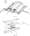
- FIG. 14 is a schematic exploded view of the connection structure in FIG. 13 .
- FIG. 15 is a schematic structural diagram of the connection structure in the foldable screen device in another direction according to this embodiment of this application.
- FIG. 16 is a schematic exploded view of the connection structure in FIG. 15 . Similar to FIG. 13 , to facilitate observation of the connection structure 31, the first shaft cover 311 and the second shaft cover 313 are hidden in FIG. 15 . A person skilled in the art may clearly know positions and connection relationships of the first shaft cover 311 and the second shaft cover 313 relative to other components of the connection structure 31 with reference to other accompanying drawings.
- the electrical connection line 4 including a flexible printed circuit board 41, a cable 42 and the like is located between the positioning piece 312 and the first shaft cover 311, and the positioning piece 312 is located between the first shaft cover 311 and the second shaft cover 313.
- Mutual matching structures and specific connection manners between the positioning piece 312, the first shaft cover 311, and the second shaft cover 313 have been described in detail in the foregoing implementations, and details are not described herein again.
- the positioning piece 312 and the first shaft cover 311 jointly position the electrical connection line 4
- the positioning piece 312 and the first shaft cover 311 do not need to clamp two opposite sides of the electrical connection line 4, but only need to jointly define a space for positioning the electrical connection line 4, to limit the electrical connection line 4 in the space.
- a channel through which the electrical connection line 4 can pass is actually formed between the positioning piece 312 and the first shaft cover 311.
- the channel has two opposite side channel walls formed by the positioning piece 312 and the first shaft cover 311 respectively, and two ends of the channel are respectively connected to space inside the two frames. Therefore, the electrical connection line 4 can enter the channel from one of the frames, and extend to the other frame through the channel.
- the part When a part that is of the electrical connection line 4 and that is located between the positioning piece 312 and the first shaft cover 311 tends to bend and deform, the part is limited by the channel walls, that is, the part is limited only in a region inside the channel, and cannot be greatly bent out of the channel.
- the positioning piece 312 and the first shaft cover 311 clamp the electrical connection line 4 in a Z-axis direction. Therefore, a clamped part of the electrical connection line 4 is constrained in the Z-axis direction, and a large amplitude of bending displacement cannot be generated. Constrained by the positioning piece 312 and end parts of the electrical connection line 4, a bending deformation amplitude of a part that is of the electrical connection line 4 and that is not clamped by the positioning piece 312 is also largely reduced, and overall displacement and a deformation amount of the electrical connection line 4 are controlled.
- connection structure 31 and components such as the hinges 32 in the rotating shaft assembly 3 are located at different positions in an axial direction of the rotating shaft 321, the channel formed by the connection structure 31 and components such as the hinges 32 used to be connected to the frames may also be located at different positions in the axial direction of the rotating shaft 321.
- structures such as the articulated arm 322 in the hinge 32 drives the frame to rotate around the rotating shaft 321, components such as the positioning piece 312 and the first shaft cover 311 that form the channel still have relatively static positions, the channel does not deform or change in another state due to rotation of the rotating shaft 321, and a structure of the channel is relatively stable and reliable.
- the electrical connection line 4 may be pre-positioned on the rotating shaft assembly 3 by using an attraction force between magnetic pieces or other pieces that can be attracted with each other.
- the first shaft cover 311 and the positioning piece 312 in the rotating shaft assembly 3 jointly clamp and position the electrical connection line 4, and therefore, a first magnetic piece 314 and a second magnetic piece 315 that can be attracted with each other may be disposed. At least one of the first magnetic piece 314 and the second magnetic piece 315 is relatively fastened to the entire rotating shaft assembly 3. The first magnetic piece 314 and the second magnetic piece 315 are located on the two opposite sides of the electrical connection line 4. In this way, the electrical connection line 4 is pre-positioned on the rotating shaft assembly 3 by using the mutual attraction force of the first magnetic piece 314 and the second magnetic piece 315.
- the first magnetic piece 314 and the second magnetic piece 315 may be made of a permanent magnetic material or a soft magnetic material.
- one of the first magnetic piece 314 and the second magnetic piece 315 may be a magnet, and the other may be a soft magnet.
- the first magnetic piece 314 is a magnet
- the second magnetic piece 315 is a soft magnet
- the first magnetic piece 314 is a soft magnet
- the second magnetic piece 315 is a magnet.
- both the first magnetic piece 314 and the second magnetic piece 315 may be magnets, and the first magnetic piece 314 and the second magnetic piece 315 have opposite polarities.
- the soft magnet may be a magnetizable iron part, a steel part, or the like.
- the first magnetic piece 314 and the second magnetic piece 315 are configured to assist in positioning the electrical connection line 4, the first magnetic piece 314 and the second magnetic piece 315 may have a plurality of different installation positions.
- the first shaft cover 311 and another main body structure of the rotating shaft assembly 3 need to be assembled and serve as an installation reference, and then structures such as the electrical connection line 4, the positioning piece 312, and the second shaft cover 313 are installed in sequence. Therefore, the first magnetic piece 314 or the second magnetic piece 315 is installed on the first shaft cover 311.
- the first magnetic piece 314 may be disposed on the first shaft cover 311, and the second magnetic piece 315 is located on the positioning piece 312. Because the positioning piece 312 and the first shaft cover 311 are located on different sides of the electrical connection line 4, the positioning piece 312 and the first shaft cover 311 can directly clamp the electrical connection line 4 by using a magnetic force, provided that the positioning piece 312 and the first shaft cover 311 are close to each other, to complete pre-positioning of components such as the electrical connection line 4 and the positioning piece 312.
- the first magnetic piece 314 and the second magnetic piece 315 may also depend on the mutually attracted magnetic force, to generate, between the positioning piece 312 and the first shaft cover 311, torques that are close to each other, to assist in positioning the electrical connection line 4.
- the electrical connection lines 4 may be used to carry the magnetic pieces.
- the first magnetic piece 314 may be disposed on the first shaft cover 311, and the second magnetic piece 315 is disposed on the electrical connection line 4.
- the second magnetic piece 315 and the first magnetic piece 314 may be attracted with each other, and are positioned on the first shaft cover 311 together with the electrical connection line 4.
- the electrical connection line 4 can be pre-positioned on the first shaft cover 311 without participation of the positioning piece 312.
- the second magnetic piece 315 may be specifically disposed on the electrical connection line 4 in a plurality of manners.
- the second magnetic piece 315 may be disposed on a plate surface of the electrical connection line 4 in a bonding manner or the like, to be integrated with the electrical connection line 4; or a bearing structure that can carry the second magnetic piece 315 is disposed on the electrical connection line 4, and the second magnetic piece 315 is installed in the bearing structure, to implement relative positioning of the electrical connection line 4 and the second magnetic piece 315.
- the first magnetic piece 314 and the second magnetic piece 315 may be disposed at different positions on the first shaft cover 311, the positioning piece 312, and the electrical connection line 4, provided that the first magnetic piece 314 and the second magnetic piece 315 have relative positions and the positioning piece 312 and the first shaft cover 311 can be close to each other by using a magnetic force between the first magnetic piece 314 and the second magnetic piece 315.
- the first magnetic piece 314 and the second magnetic piece 315 may have relatively regular shapes.
- both the first magnetic piece 314 and the second magnetic piece 315 may be in a shape of a cuboid.
- first magnetic piece 314 and the first shaft cover 311, or the second magnetic piece 315 and the positioning piece 312 may alternatively form an integrated structure.
- the connection structure 31 actually includes only the first magnetic piece 314 or only the second magnetic piece 315.
- the entire positioning piece 312 or the entire first shaft cover 311 is made of a soft magnet.
- the first magnetic piece 314 is disposed on the first shaft cover 311, the first magnetic piece 314 is a magnet, and the entire positioning piece 312 is a soft magnet that can be attracted by the magnet.
- the second magnetic piece 315 is disposed on the positioning piece 312, the second magnetic piece 315 is a magnet, and the first shaft cover 311 is made of a soft magnet. In this way, a structure of the first shaft cover 311 or the positioning piece 312 can be simplified, and manufacturing difficulty can be reduced.
- the electrical connection line 4 may be disposed on an assembly component in advance in an assembly process of the rotating shaft assembly 3, to prevent the electrical connection line 4 from being detached from an assembly position due to external pulling or other forces, and effectively reduce assembly difficulty.
- the first shaft cover 311 and the positioning piece 312 can clamp tightly, or the electrical connection line 4 can be attached to the first shaft cover 311, to assist in positioning the electrical connection line 4.
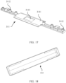
- FIG. 17 is a schematic diagram of a structure of the first shaft cover in the foldable screen device according to this embodiment of this application.
- the first shaft cover 311 may occupy an entire length direction of the rotating shaft assembly 3, to serve as a connection basis between the connection structure 31 and the hinge 32.
- the positioning piece 312 and the second shaft cover 313 may be assembled by using the first shaft cover 311 as a positioning and assembly reference.
- the first shaft cover 311 includes a first fixing surface 3111 located in the middle region of the first shaft cover 311 and connection rods 3112 located in end regions.
- connection rod 3112 may be configured to be connected to the hinge 32 or another structure, and the first fixing surface 3111 may be configured to arrange the positioning piece 312. To enable the rotating shaft assembly 3 to evenly bear a force, the connection rods 3112 are symmetrically distributed in a length direction of the first shaft cover 311.
- a first installation slot 3113 may be provided on the first fixing surface 3111 of the first shaft cover 311. Both a shape and a size of the first installation slot 3113 match those of the first magnetic piece 314, so that the first magnetic piece 314 can be accommodated in the first installation slot 3113.
- the first installation slot 3113 may be connected to the first magnetic piece 314 by using a bonding agent or in a manner of interference fit or the like.
- FIG. 18 is a schematic diagram of a structure of the second shaft cover in the foldable screen device according to this embodiment of this application.
- the second shaft cover 313 extends in an entire length direction of the rotating shaft assembly 3, which is similar to that of the first shaft cover 311.
- An inner surface of the second shaft cover 313 is in an arc shape.
- FIG. 19 is a schematic diagram of a front structure of the positioning piece in the foldable screen device according to this embodiment of this application.
- FIG. 20 is a schematic diagram of a back structure of the positioning piece 312 in a terminal device according to this embodiment of this application.
- a first positioning part 3122 is disposed on a side that is of the positioning piece 312 and that is close to the first shaft cover 311, and the first positioning part 3122 may be connected to the first shaft cover 311, so that the positioning piece 312 and the first shaft cover 311 have fixed relative positions.
- a second positioning part 3121 is disposed on a side that is of the positioning piece 312 and that is close to the second shaft cover 313, and the second positioning part 3121 may be connected to the second shaft cover 313, so that the positioning piece 312 and the second shaft cover 313 have fixed relative positions.
- both the first positioning part 3122 and the second positioning part 3121 may have structures such as positioning rods or positioning protrusions, and the first positioning part 3122 and the second positioning part 3121 respectively press against opposite surfaces of the first shaft cover 311 or the second shaft cover 313, so that the positioning piece 312 is firmly clamped between the first shaft cover 311 and the second shaft cover 313.
- the first positioning part 3122 of the positioning piece 312 protrudes outward from a main body of the positioning piece 312, and a height of the top of the first positioning part 3122 is greater than a height of another part on the side surface of the positioning piece 312. Therefore, when the first positioning part 3122 is connected to the first shaft cover 311, a gap is formed between the main body of the positioning piece 312 and the first shaft cover 311. The gap may be used to allow penetration of the electrical connection line 4.
- a side that is of the main body of the positioning piece 312 and that faces the first shaft cover 311 further has a second fixing surface 3125, and a gap for allowing penetration of the electrical connection line 4 is formed between the second fixing surface 3125 and the first shaft cover 311, so that the electrical connection line 4 can be clamped in a region between the first shaft cover 311 and the second fixing surface 3125.
- a position of a part that is of the electrical connection line 4 and that is clamped by the positioning piece 312 and the first shaft cover 311 is limited, and this part cannot generate a large amplitude of bending and deformation with rotation of the frame.
- the positioning piece 312 is connected to the first shaft cover 311 by using the first positioning part, the first positioning part protrudes toward the outer side of the second fixing surface 3125 until the first positioning part presses against a corresponding part of the first shaft cover 311.
- first positioning parts 3122 distributed at different positions of the main body of the positioning piece 312.
- the first positioning part 3122 may be in a convex column form.
- the positioning piece 312 further includes a second positioning part 3121.
- the second positioning part 3121 may be of a structure such as a protrusion, and may press against an inner surface of the second shaft cover 313.
- the top of the protrusion may be in an arc shape matching a shape of the inner surface of the second shaft cover 313. In this way, the top of the second positioning part 3121 firmly presses against the inner surface of the second shaft cover 313 and is positioned.
- the positioning piece 312 and the second shaft cover 313 can be reliably positioned.
- a structure that limits horizontal (namely, a Y-axis direction in the figure) movement of the electrical connection line 4 may be disposed on the positioning piece 312.
- the positioning piece 312 may limit a transverse position of the electrical connection line 4 by using a structure such as a positioning protrusion.
- a third positioning part 3127 may be disposed on the main body of the positioning piece 312.
- the third positioning part 3127 is located on a side of the electrical connection line 4, to prevent the electrical connection line 4 from moving toward the third positioning part 3127 on the side of the electrical connection line 4.
- the third positioning part 3127 may be of a structure such as a protrusion protruding from the second fixing surface 3125. In this way, the electrical connection line 4 is constrained by a side wall of the third positioning part 3127, and therefore, movement in a direction parallel to the second fixing surface 3125 (a Y-axis direction in the figure) is blocked.
- the third positioning parts 3127 may cooperate with the first positioning part 3122 to perform horizontal positioning on the electrical connection line 4.
- the third positioning parts 3127 are located on one side of the electrical connection line 4, and the other side of the electrical connection line 4 is the first positioning part 3122, the first positioning part 3122 and the third positioning parts 3127 can jointly constrain a transverse position of the electrical connection line 4.
- the third positioning part 3127 may extend in a length direction of the electrical connection line 4, to position different parts of the electrical connection line 4 in the length direction.
- the positioning piece 312 is provided with a second installation slot 3129. Both a size and a shape of the second installation slot 3129 match those of the second magnetic piece 315, so that the second magnetic piece 315 is fastened to the positioning piece 312.
- the second installation slot 3129 may be located on a surface that is of the positioning piece 312 and that faces the first shaft cover 311, namely, the second fixing surface 3125.
- the second magnetic piece 315 may be connected to the second installation slot 3129 through bonding or in a manner of interference fitting or the like.
- first shaft cover 311 or the second shaft cover 313 may have a structure matching the positioning piece 312.
- a structure whose shape matches a shape of the first positioning part 3122 or the second positioning part 3121 may be disposed, for example, a groove or a positioning hole (not shown in the figure). In this way, the first positioning part or the second positioning part may be inserted into the groove or the positioning hole, to complete fastening of the positioning piece 312 relative to the first shaft cover 311 and the second shaft cover 313.
- the positioning piece 312 may alternatively be connected and fastened only to the first shaft cover 311.
- the positioning piece 312 may be connected to the first shaft cover 311 in a manner such as a clamping manner.
- the positioning piece 312 may also be connected and fastened to the first shaft cover 311, the second shaft cover 313, or another structure of the rotating shaft assembly 3 by using a threaded fastener or in a manner such as a bonding manner.
- Other connection manners of the positioning piece 312 in the connection structure 31 are not described herein.
- the electrical connection line 4 may also move in a length direction of the electrical connection line 4, that is, the electrical connection line 4 slides relative to the positioning piece 312 in an X-axis direction.
- a relatively large length difference may exist between lengths of parts that are of the electrical connection line 4 and that are located on two sides of the positioning piece 312, and a relatively long part may still generate a large amplitude of bending deformation.
- a corresponding limiting structure may be disposed on the positioning piece 312.
- different parts or segments of the electrical connection line 4 may have different extension directions by using a bending and deformation feature of the electrical connection line 4 through limiting and guiding the limiting structure.
- the electrical connection line 4 is affected by an external force to generate a moving trend in the length direction of the electrical connection line 4, a length direction of each part of the electrical connection line 4 extending in different directions is inconsistent with a direction of the external force.
- the electrical connection line 4 may include a plurality of different types such as a flexible printed circuit board 41 and a single cable 42.
- different limiting structures may be used on the positioning piece 312 to position the electrical connection line 4. The following separately describes in detail limiting structures of the positioning piece 312 by using examples in which the limiting structures position the flexible printed circuit board 41 and the single cable 42.
- the entire flexible printed circuit board 41 is of a bendable thin board structure, has a relatively large width and length, but has a relatively small size in a thickness direction of the flexible printed circuit board 41, namely, a direction perpendicular to aboard surface direction of the flexible printed circuit board 41. Therefore, to reduce a size of the limiting structure, when the limiting structure of the positioning piece 312 further limits the flexible printed circuit board 41, the limiting structure of the positioning piece 312 may limit and fasten the flexible printed circuit board 41 in the direction perpendicular to the board surface direction of the flexible printed circuit board 41.
- the limiting structure of the positioning piece 312 may be located on one side of a board surface of the flexible printed circuit board 41, so that the flexible printed circuit board 41 is bent to some extent, and a bending direction is perpendicular to the board surface direction of the flexible printed circuit board 41.
- a bending direction is perpendicular to the board surface direction of the flexible printed circuit board 41.
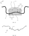
- FIG. 21 is a schematic diagram of a connection between the connection structure and the flexible printed circuit board in the foldable screen device according to this embodiment of this application.
- both the first fixing surface 3111 of the first shaft cover 311 and the second fixing surface 3125 of the positioning piece 312 may be concave-convex surfaces, and concave and convex directions of the concave-convex surfaces face a thickness direction of the flexible printed circuit board 41.
- the board surface of the flexible printed circuit board 41 presents a shape matching shapes of the first fixing surface 3111 and the second fixing surface 3125, that is, the plate surface is also bent toward the thickness direction of the flexible printed circuit board 41 to form protrusions or recesses.
- the positioning piece 312 can fasten the flexible printed circuit board 41 in the length direction of the flexible printed circuit board 41 by using the second fixing surface 3125 that has a concave-convex shape.
- a channel having a concave-convex shape is formed between the positioning piece 312 and the first shaft cover 311, and a corresponding concave-convex shape is also formed on the flexible printed circuit board 41 that passes through the channel.
- the flexible printed circuit board 41 is in contact with a concave-convex channel wall, and is blocked by the channel wall, to prevent the flexible printed circuit board 41 from moving forward and backward in the length direction of the flexible printed circuit board 41.
- the plurality of concave-convex shapes may be sequentially arranged in the length direction of the flexible printed circuit board 41.
- the flexible printed circuit board 41 may be simultaneously limited by the plurality of concave-convex shapes, and correspondingly has a plurality of curved segments or bending segments.
- the plurality of curved segments or bending segments may work together to generate resistance, which has a relatively good positioning effect to the flexible printed circuit board 41 in the length direction.
- a shape and a size of the concave-convex shape are limited by bending performance of the flexible printed circuit board 41.
- a height of a protrusion or a depression in a single concave-convex shape is greater than a minimum bendable radius of the flexible printed circuit board 41, to avoid damage or even rupture caused by excessive bending of the flexible printed circuit board 41.
- the first fixing surface 3111 of the first shaft cover 311 and the second fixing surface 3125 of the positioning piece 312 may have relatively simple shapes.
- the first fixing surface 3111 and the second fixing surface 3125 each may have a convex or concave shape.
- the convex or concave shape matches a shape of a corresponding part on the first shaft cover 311, so that the flexible printed circuit board 41 has an entire curved part or an entire bent part in a space formed between the second fixing surface 3125 and the first shaft cover 311, and the curved part presses against a convex or concave part of the second fixing surface 3125, to position the flexible printed circuit board 41 in the length direction.
- an example in which the second fixing surface 3125 has a concave shape and the first fixing surface 3111 has a corresponding convex shape is used for description.
- the first fixing surface 3111 and the second fixing surface 3125 may generate a convex or concave shape in a straight-line bending manner.
- the first fixing surface 3111 has a plurality of straight-line bending segments 3111a
- the second fixing surface 3125 also has a plurality of straight-line bending segments 3125a correspondingly.
- the straight-line bending segments 3111a of the first fixing surface 3111 form a protrusion shape.
- the straight-line bending segments 3125a of the second fixing surface 3125 form a recess shape.
- a bent channel is formed, and the channel protrudes to one side of the positioning piece 312.
- a protrusion and a recess formed by bending a straight line may have a relatively large bending angle, and have a relatively good fastening effect on the flexible printed circuit board 41.
- the second fixing surface 3125 may be an arc-shaped surface, and the first fixing surface 3111 that is of the first shaft cover 311 and that faces the second fixing surface 3125 is also an arc-shaped surface.
- the first fixing surface 3111 and the second fixing surface 3125 each do not have a bending-angle structure such as an acute edge or a sharp angle.
- a part that is of the flexible printed circuit board 41 and that is in contact with the positioning piece 312 and a part that is of the flexible printed circuit board 41 and that is in contact with the first shaft cover 311 are arc surfaces with smooth transition. No fold or surface scratch is generated on the surface of the flexible printed circuit board 41 due to pressure of the acute edge.
- the positioning piece 312 may further have another structure or shape used to position the flexible printed circuit board 41 in a length direction. Details are not described herein.
- the electrical connection line 4 may include one or more flexible printed circuit boards 41.
- the plurality of flexible printed circuit boards 41 may be disposed in a top-down stacking manner, and are fastened together by the first shaft cover 311 and the positioning piece 312 in the rotating shaft assembly 3.
- the electrical connection line 4 may further include scattered cables 42.
- the cable 42 is usually disposed as a single cable. In this way, a radial size of the cable 42 is far less than a size of the cable 42 in a length direction. Therefore, when the positioning piece 312 is used to position the cable 42, compared with the flexible printed circuit board 41, the positioning piece 312 requires a more compact limiting structure.
- the second fixing surface 3125 of the positioning piece 312 is provided with a guide groove 3123, and a cable segment that is of the cable 42 and that is located between the positioning piece 312 and the first shaft cover 311 may be partially or all buried in the guide groove 3123.
- the guide groove 3123 may correspondingly have a plurality of different guide groove shapes and structures, and cooperate with the cable 42 for positioning. The following specifically describes various possible forms of the guide groove 3123 and corresponding limiting manners of the cable 42.
- FIG. 22 is a schematic diagram of a structure of the cable according to this embodiment of this application.
- a positioning structure may be disposed on an outer surface of the cable 42.
- the positioning structure may cooperate with a corresponding structure of the guide groove 3123, so that the positioning piece 312 positions the cable 42 in a length direction of the cable 42.
- the cable 42 is fastened in the guide groove 3123 of the positioning piece 312, a structure that matches the positioning structure of the cable 42 may be disposed in the guide groove 3123.
- the positioning structure on the outer surface of the cable 42 may be an axial positioning protrusion 421.
- the axial positioning protrusion 421 protrudes in a radial direction of the cable 42.
- FIG. 23 is a schematic diagram of a connection structure in a first direction when the positioning piece is connected to the cable according to this embodiment of this application.
- FIG. 24 is a schematic diagram of a connection structure in a second direction when the positioning piece is connected to the cable according to this embodiment of this application.
- the guide groove 3123 may pass through the positioning piece 312 in a length extension direction of the cable 42, a groove opening of the guide groove 3123 faces the first shaft cover 311, and openings of the guide groove 3123 are formed in end surfaces of two opposite sides of the positioning piece 312.
- the cable 42 may penetrate into the guide groove 3123 through the two opposite openings. Slot walls on the two sides of the guide groove 3123 may limit a radial position of the cable 42. In this way, the cable 42 is constrained in the guide groove 3123.
- a recess part 3124 corresponding to the axial positioning protrusion 421 may be disposed in the guide groove 3123.
- a shape and a position of the recess part 3124 correspond to a shape and a position of the axial positioning protrusion 421.
- the positioning structure of the cable 42 may have a plurality of different forms.
- an injection-molded part may be used to form a positioning structure of the cable 42.
- the injection-molded part may be formed on the outer surface of the cable 42 in an injection molding manner.
- strength of a connection between the injection-molded part and a main body of the cable 42 is relatively high, and a structure is relatively reliable.
- another material or component may be used to form a positioning structure on the outer surface of the cable 42. This is not limited herein.
- the guide groove 3123 needs to have an avoidance notch 3126 that is convenient to place the cable 42.
- a size and a shape of the avoidance notch 3126 are adapted to a size and a shape of the cable 42 having the axial positioning protrusion 421. Specifically, a size of the avoidance notch 3126 in a radial direction of the cable 42 is greater than a maximum radial size of the cable 42 having the axial positioning protrusion 421, so that the cable 42 can be placed into the guide groove 3123 through the avoidance notch 3126.
- a position of the avoidance notch 3126 may be opposite to or staggered from the recess part 3124. After entering the guide groove 3123, the cable 42 may move to a position at which the axial positioning protrusion 421 is matched and clamped with the recess part 3124, so that the cable 42 is positioned, as specifically shown in FIG. 22 .
- a main body of the positioning piece 312 provided with the avoidance notch 3126 and the guide groove 3123 has a relatively complex shape and contour, and the positioning piece 312 may be integrally formed in a manner such as injection molding.
- the positioning piece 312 may be provided with an auxiliary hole 3128, and both the avoidance notch 3126 and the recess part 3124 are connected to the auxiliary hole 3128, so that a mold can extend into the avoidance notch 3126 and the recess part 3124 through the auxiliary hole 3128, to facilitate injection molding of the positioning piece 312.
- auxiliary hole 3128 For a specific shape and position of a structure such as the auxiliary hole 3128, refer to the foregoing illustration of the positioning piece 312.
- the guide groove 3123 may be bent toward a thickness direction of the flexible printed circuit board 41.
- the guide groove 3123 may form a concave-convex shape similar to that of the second fixing surface 3125, to limit the cable 42 in the length direction of the cable 42.
- edges of the guide groove 3123 are higher than a middle part of the guide groove 3123, so that steps 3123a are formed at the edges of the guide groove 3123.
- steps 3123a For a specific shape and structure of the step 3123a, refer to the foregoing diagram of the positioning piece 312.
- FIG. 25 is a schematic diagram of another connection structure when a positioning piece is connected to a cable according to an embodiment of this application.
- a guide groove 3123 of a positioning piece 312 has at least one bending segment.
- a bending direction of the bending segment faces a radial direction of a cable 42.
- the cable 42 disposed in the guide groove 3123 forms a bending shape under pressure of groove walls of the guide groove 3123.
- the bending groove walls of the guide groove 3123 may block movement of the cable 42, so that the cable 42 is maintained at an original position.
- the bending direction of the guide groove 3123 may protrude to a side of a flexible printed circuit board 41.
- an end part of the cable 42 extends to a side away from the flexible printed circuit board, thereby preventing interference between the cable 42 and the flexible printed circuit board 41.
- the guide groove 3123 may directly clamp the cable 42 inside the guide groove 3123, and limitation of the flexible printed circuit board 41 in an X-axis direction is completed without the need of cooperation between a second fixing surface 3125 and a first shaft cover 311.
- the guide groove 3123 may have a uniform groove depth, and a groove width of a part between groove walls on two sides of the guide groove 3123 may match an outer diameter of the cable 42, so that the cable 42 is limited and fastened.
- the entire guide groove 3123 extends in a width direction (a Y-axis direction) of the positioning piece 312, the guide groove 3123 has the bending segment, and the bending segment is bent toward a length direction (an X-axis direction in the figure) of the positioning piece 312.
- the guide groove 3123 in FIG. 25 has a plurality of bending segments that are sequentially connected. These bending segments guide a plurality of different segments of the cable 42 in different directions.
- the guide groove 3123 causes relatively great resistance to the cable 42 to prevent the cable 42 from sliding relative to a cable groove in a length direction.
- the bending segments of the guide groove 3123 may be symmetrically disposed relative to a central axis of the positioning piece 312.
- the central axis of the positioning piece 312 serves as a boundary, and the cable 42 is divided into two segments connected to different frames. The bending segments on different sides of the central axis impose close or even same resistance on the cable 42.
- the cable segments on both sides of the positioning piece 312 are under a same stress and generate same deformation, and a case in which a segment of the cable 42 on one side of the positioning piece 312 generates large deformation while a segment of the cable 42 on the other side of the positioning piece 312 generates slight deformation is not generated.
- smooth transition may be performed between the bending segments by using a curved surface, to prevent the cable 42 from being scratched due to sharp angles or acute edges of the guide groove 3123.
- a bending angle and a bending radius formed by the bending segments are greater than a minimum bendable radius of the cable 42, to avoid damage or break of the cable 42 located in the guide groove 3123 due to an excessively large bending degree of the guide groove 3123.
- a bonding agent may be used to assist in positioning the flexible printed circuit board 41, the cable 42, and the like.
- a dispensing operation may be performed on a part that is of the flexible printed circuit board 41 or the cable 42 and that is in contact with the rotating shaft assembly 3, and the flexible printed circuit board 41 or the cable 42 and the positioning piece 312 are fastened together by using a bonding force of the bonding agent.
- the electrical connection line 4 may include both the flexible printed circuit board 41 and a cable 42 that is arranged in a single manner.
- the guide groove 3123 of the positioning piece 312 is located outside a region that is of the second fixing surface 3125 and that is attached to the flexible printed circuit board 41.
- regions that are of the guide groove 3123 and the second fixing surface 3125 and that are used to position the flexible printed circuit board 41 are disposed in parallel.
- the flexible printed circuit board 41 and the single arranged cable 42 are also arranged in parallel.
- the frame To connect an end part of the electrical connection line 4 to a corresponding frame, the frame also has a fastening structure for fastening the electrical connection line 4. In this way, determined relative positions exist between an end part of the electrical connection line 4 and the frame. No matter whether the frame rotates to any position, the end part of the electrical connection line 4 is reliably connected to the frame, and is electrically connected to a corresponding component such as a mainboard, an antenna, or a flexible screen in the frame.
- a corresponding component such as a mainboard, an antenna, or a flexible screen in the frame.
- the electrical connection line 4 may include different components such as the flexible printed circuit board 41 and the single cable 42, and the flexible printed circuit board 41 and the single cable 42 have different structures and shapes. Therefore, for the flexible printed circuit board 41 and the cable 42, the frame may fasten ends of the flexible printed circuit board 41 and the cable 42 by using different fastening structures.
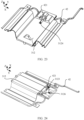
- FIG. 26 is a schematic diagram of a connection structure between the electrical connection line and the frame in the foldable screen device according to this embodiment of this application.
- FIG. 27 is a schematic exploded view of the connection structure between the electrical connection line and the frame in FIG. 26 .
- a reinforcement steel sheet 411 is disposed at an end part of the flexible printed circuit board 41.
- the reinforcement steel sheet 411 may be connected to the end part of the flexible printed circuit board 41 in a bonding or press-fitting manner.
- the reinforcement steel sheet 411 has relatively strong mechanical performance, and may be provided with a fastening structure to bear a pulling force generated when the flexible printed circuit board 41 is fastened.
- a first connection hole 4111 is disposed in the reinforcement steel sheet 411 at the end part of the flexible printed circuit board 41, a direction of the first connection hole 4111 is perpendicular to a board surface direction of the flexible printed circuit board 41, and a second connection hole 11 corresponding to the first connection hole 4111 is disposed in the first frame 1.
- a fastener may pass through the first connection hole 4111 and the second connection hole 11 in sequence, so that the end part of the flexible printed circuit board 41 is fastened to the first frame 1.
- the reinforcement steel sheet 411 is disposed at the end part of the flexible printed circuit board 41, and the first connection hole 4111 is disposed in the reinforcement steel sheet 411.
- the fastener may be a common fastener, for example, a threaded fastener such as a screw, or another fastener commonly used by a person skilled in the art such as a stud or a rivet, which is not limited herein.
- the reinforcement steel sheet 411 maintains a relatively small thickness and also has relatively strong mechanical strength. Therefore, the end part of the flexible printed circuit board 41 can be reliably fastened.
- a length direction of the reinforcement steel sheet 411 may be consistent with a width direction of the flexible printed circuit board 41. In this way, in an entire width direction of the flexible printed circuit board 41, the flexible printed circuit board 41 is tightly pressed and fastened by the reinforcement steel sheet 411, thereby achieving a better positioning effect on the end part of the flexible printed circuit board 41.
- an elastic cushion 412 may be disposed on the frame, and the elastic cushion 412 is located between the frame and the reinforcement steel sheet 411.
- the elastic cushion 412 has a specific deformation capability, a specific gap is formed between the reinforcement steel sheet 411 and the corresponding frame, and an axial position of the reinforcement steel sheet 411 relative to the frame may change within a range of the gap, so that a position of a connection point between the end part of the flexible printed circuit board 41 and the frame may be slightly regulated.
- the error can be compensated by elastic deformation of the elastic cushion 412, thereby avoiding a risk that the flexible printed circuit board 41 is tensed or even broken due to the insufficient length.
- the elastic cushion 412 may be made of a flexible material such as foam. Therefore, the elastic cushion 412 can also protect a surface of the end part of the flexible printed circuit board 41 to prevent an outer surface of the flexible printed circuit board 41 from being damaged by an external force.
- the cushion 412 may cover a region in which the end part of the flexible printed circuit board 41 is correspondingly connected to a connecting piece.
- the elastic cushion 412 may be made of insulation foam.
- a positioning steel sheet may be further disposed on the frame, and a third connection hole is disposed in the positioning steel sheet.
- the positioning steel sheet may be disposed on the reinforcement steel sheet 411, and the positioning steel sheet is located on a side that is of the reinforcement steel sheet 411 and that is away from the frame.
- the fastener may sequentially pass through the third connection hole, the first connection hole, and the second connection hole, so that the positioning steel sheet, the elastic cushion 412, the reinforcement steel sheet 411, and the frame are fastened together in an axial direction of the fastener.
- the elastic cushion 412 may have a plurality of different positions.
- the elastic cushion 412 may be disposed between the reinforcement steel sheet 411 and the frame, and the elastic cushion 412 may alternatively be disposed between the positioning steel sheet and the reinforcement steel sheet 411.
- the elastic cushion 412 may be disposed between the reinforcement steel sheet 411 and the frame, or between the positioning steel sheet and the reinforcement steel sheet 411.
- a cable groove 12 may be provided in the frame, and the cable 42 is buried in the cable groove 12. A position and a direction of the cable 42 may be constrained by using the cable groove 12.
- the frame may use another positioning structure or positioning manner to assist in positioning the cable 42.
- the cable 42 may be bonded to the cable groove 12 by using a bonding agent. Specifically, after the cable 42 is installed inside the cable groove 12, the cable 42 and the cable groove 12 may be bonded together in a glue dispensing manner.
- the reinforcement steel sheet 411 may also be configured to assist in positioning the cable 42.
- the reinforcement steel sheet 411 may cover a region in which the cable groove 12 is located, and is pressed on an outer side of the cable 42. In this case, displacement of the cable 42 in each circumferential direction is constrained by the reinforcement steel sheet 411 or the cable groove, and therefore, the position of the cable 42 is limited.
- the same reinforcement steel sheet 411 is used to position the flexible printed circuit board 41 and the cable 42. In this way, limited space inside the foldable screen device can be effectively used, so that the device is more compact.
- a material having relatively good mechanical performance may also be used to replace the reinforcement steel sheet 411.
- a high-strength plastic material may be used to reinforce and position the end part of the flexible printed circuit board 41.
- the surface of the cable 42 may be further wrapped with acetic acid cloth for protecting the cable 42.
- the acetic acid cloth may be located between an outer surface of the cable 42 and a contact surface of another structure, and has a cushioning and insulation effect to some extent.
- the surface of the cable 42 may also be protected by using an injection molding structure or other manners well known by a person skilled in the art, which is not limited herein.
- the frame may further have a positioning structure and a positioning component in another form and structure. This is not limited herein.
- FIG. 28 is a schematic diagram of an inner-side connection of the flexible protective cover in the foldable screen device according to this embodiment of this application.
- FIG. 29 is a schematic diagram of an outer-side connection of the flexible protective cover in the foldable screen device according to this embodiment of this application. As shown in FIG. 28 and FIG.
- edges of two opposite sides of the flexible protective cover 5 are respectively connected to two frames, and a main body of the flexible protective cover 5 covers a side of the electrical connection line 4.
- the flexible protective cover 5 is blocked between the electrical connection line 4 and an outer structure, to prevent the outer structure from contacting the electrical connection line 4.
- the flexible printed circuit board 41 and the cable 42 in the electrical connection line 4 mostly face the inner side of the foldable screen device, that is, opening and closing ends of the foldable screen device are bent. Therefore, accordingly, the flexible protective cover 5 is disposed on a side that is of the electrical connection line 4 and that is close to the opening and closing ends of the foldable screen device.
- a size of the flexible protective cover 5 in a length direction of the rotating shaft 321 may be greater than or equal to a size of a region occupied by the electrical connection line 4 in this direction. In this case, parts of the electrical connection line 4 between the two frames are all covered and protected by the flexible protective cover 5.
- the flexible protective cover 5 is made of a soft material. Therefore, even if the electrical connection line 4 comes into contact with the flexible protective cover 5, the flexible protective cover 5 does not damage a surface of the electrical connection line 4.
- the flexible protective cover 5 may be a corrugated protective cover.
- the entire flexible protective cover 5 has an uneven corrugated surface, and the corrugated surface may be correspondingly unfolded or folded when the foldable screen device is opened or closed, to form protection regions of different sizes to adapt to different opening and closing angles of the foldable screen device.
- Different components may be disposed in different frames of the foldable screen device, and these components have different power and heat.
- different frames may have a relatively large temperature difference. Consequently, display effects of parts that are of the flexible screen and that correspond to the different frames are affected, and a display uniformity problem such as a color cast in a local area of the screen is caused. Therefore, the flexible protective cover 5 connected between the different frames may have a specific heat transfer capability, to transfer heat between the different frames, reduce the temperature difference between the different frames, and improve display uniformity of the flexible screen.
- the flexible protective cover 5 may be made of a thermally conductive film.
- the thermally conductive film may be made of a material such as graphite or carbon fiber, and has a relatively good thermal conductivity.
- the flexible protective cover 5 connected between the different frames can transfer heat on a frame to another frame, so that temperatures of the two frames are relatively uniform.
- all parts that are of the flexible screen and that are correspondingly disposed on the different frames also have relatively good display uniformity.
- the flexible protective cover 5 may have a heat dissipation surface 51 that fits the frame (not shown in the figure).
- the heat dissipation surface 51 has a relatively large heat dissipation area. Therefore, the flexible protective cover 5 can implement a relatively fast heat conduction speed by using the heat dissipation surface 51 and the frame, so that there is relatively good temperature uniformity between the first frame 1 and the second frame 2.
- a foldable screen device includes a first frame, a second frame, and a rotating shaft assembly connected between the first frame and the second frame.
- a connection structure in the rotating shaft assembly forms a channel through which an electrical connection line can pass and that can fasten the electrical connection line.
- a magnetic piece is disposed to assist in positioning the connection structure and the electrical connection line. In this way, the electrical connection line is positioned by the rotating shaft assembly, so that bending deformation generated by the electrical connection line when the foldable screen device is folded is relatively small, and a bending amount is prone to control. Therefore, connection reliability is high.
- FIG. 30 is a schematic diagram of a cross section of a connection structure in another foldable screen device according to an embodiment of this application.
- FIG. 31 is a schematic structural diagram of the connection structure in the another foldable screen device in a first direction according to this embodiment of this application.
- FIG. 32 is a schematic structural diagram of the connection structure in the another foldable screen device in a second direction according to this embodiment of this application. As shown in FIG. 30 to FIG.
- connection structure 31 included in the rotating shaft assembly 3 of the foldable screen device in this scenario does not include a magnetic piece.
- the connection structure 31 mainly includes the first shaft cover 311, a second shaft cover 313, and the positioning piece 312.
- the positioning piece 312 is located between the second shaft cover 313 and the first shaft cover 311, and the electrical connection line 4 is located between the positioning piece 312 and the first shaft cover 311.
- the first shaft cover 311, the second shaft cover 313, and the positioning piece 312 in the connection structure 31 have structures similar to those in the foregoing scenario, and the positioning piece 312 may be installed between the first shaft cover 311 and the second shaft cover 313 by using the specific structure in the foregoing scenario.
- the connection structure 31 does not include the magnetic piece, a second fixing surface 3125 of the positioning piece 312 and a first fixing surface 3111 of the first shaft cover 311 each may be a flat surface, and no installation slot needs to be provided.
- the foldable screen device includes a first frame, a second frame, and the rotating shaft assembly connected between the first frame and the second frame.
- the connection structure in the rotating shaft assembly forms a channel through which an electrical connection line can pass and that can fasten the electrical connection line.
- the electrical connection line is positioned by the rotating shaft assembly, so that bending deformation generated by the electrical connection line when the foldable screen device is folded is relatively small, and a bending amount is prone to control. Therefore, connection reliability is high.
Landscapes
- Engineering & Computer Science (AREA)
- Signal Processing (AREA)
- Theoretical Computer Science (AREA)
- Computer Hardware Design (AREA)
- General Engineering & Computer Science (AREA)
- Physics & Mathematics (AREA)
- Human Computer Interaction (AREA)
- General Physics & Mathematics (AREA)
- Computer Networks & Wireless Communication (AREA)
- Telephone Set Structure (AREA)
- Insertion, Bundling And Securing Of Wires For Electric Apparatuses (AREA)
- Casings For Electric Apparatus (AREA)
- Mounting Of Printed Circuit Boards And The Like (AREA)
- Devices For Indicating Variable Information By Combining Individual Elements (AREA)
Claims (12)
- Vorrichtung (100) mit zusammenklappbarem Bildschirm, umfassend zwei Rahmen (1, 2), eine elektrische Verbindungsleitung (4) und eine Drehwellenbaugruppe (3), die mit den beiden Rahmen gelenkig verbunden ist, wobei die beiden Rahmen (1, 2) fähig sind, sich um Drehwellen (321) der Drehwellenbaugruppe (3) zu drehen, um geschlossen oder geöffnet zu werden; und die Drehwellenbaugruppe (3) Scharniere (32) und eine Verbindungsstruktur (31) umfasst, wobei das Scharnier (32) zwischen der Verbindungsstruktur (31) und dem Rahmen (1, 2) verbunden ist, die Verbindungsstruktur (31) einen Kanal aufweist, der durch zwei gegenüberliegende Seiten der Drehwellenbaugruppe (3) verläuft, zwei Enden der elektrischen Verbindungsleitung (4) jeweils mit den beiden Rahmen (1, 2) verbunden sind, die elektrische Verbindungsleitung (4) in den Kanal eindringt und sich der Kanal und das Scharnier (32) in einer axialen Richtung an unterschiedlichen Positionen der Drehwellenbaugruppe befinden,
dadurch gekennzeichnet, dassdie Verbindungsstruktur (31) eine erste Wellenabdeckung (311) und eine zweite Wellenabdeckung (313) umfasst, die erste Wellenabdeckung und die zweite Wellenabdeckung einander gegenüberliegend angeordnet sind, sich die erste Wellenabdeckung (311) auf einer Innenseite, die zu der Drehwellenbaugruppe (3) gehört und die nahe an Gelenkenden der Rahmen (1, 2) liegt, befindet, sich die zweite Wellenabdeckung (313) auf einer Seite, die zu der Drehwellenbaugruppe (3) gehört und die nahe an freien Enden der Rahmen (1, 2) liegt, befindet und die erste Wellenabdeckung und die zweite Wellenabdeckung einen Raum umschließen, der fähig ist, die Drehwellen (321) aufzunehmen,die Verbindungsstruktur (31) ferner ein Positionierstück (312) umfasst, sich das Positionierstück in dem Raum befindet, der durch die erste Wellenabdeckung (311) und die zweite Wellenabdeckung (313) gemeinsam umschlossen ist und der Kanal gemeinsam durch das Positionierstück (312) und einer der ersten Wellenabdeckung (311) und der zweiten Wellenabdeckung (313) gebildet ist unddie Vorrichtung (100) mit zusammenklappbarem Bildschirm ferner ein erstes Magnetstück (314) und ein zweites Magnetstück (315) umfasst, wobei das erste Magnetstück (314) an der ersten Wellenabdeckung (311) angeordnet ist, das zweite Magnetstück (315) an dem Positionierstück (312) angeordnet ist und das erste Magnetstück und das zweite Magnetstück zueinander anziehbar sind, sodass das Positionierstück (312) und die erste Wellenabdeckung (311) zueinander positioniert sind. - Vorrichtung (100) mit zusammenklappbarem Bildschirm nach Anspruch 1, wobei sich die Verbindungsstruktur (31) in einem mittleren Bereich der Drehwellenbaugruppe (3) in einer axialen Richtung befindet.
- Vorrichtung (100) mit zusammenklappbarem Bildschirm nach Anspruch 1 oder 2, wobei das Positionierstück (312) und die erste Wellenabdeckung (311) den Kanal gemeinsam umschließen.
- Vorrichtung (100) mit zusammenklappbarem Bildschirm nach einem der Ansprüche 1 bis 3, wobei sowohl das erste Magnetstück (314) als auch das zweite Magnetstück (315) Magnete sind.
- Vorrichtung (100) mit zusammenklappbarem Bildschirm nach einem der Ansprüche 1 bis 3, wobei eines des ersten Magnetstücks (314) und des zweiten Magnetstücks (315) ein Magnet und das andere ein Weichmagnet ist.
- Vorrichtung (100) mit zusammenklappbarem Bildschirm nach einem der Ansprüche 1 bis 5, wobei die elektrische Verbindungsleitung (4) eine flexible Leiterplatte (41) umfasst.
- Vorrichtung (100) mit zusammenklappbarem Bildschirm nach Anspruch 6, wobei die elektrische Verbindungsleitung (4) ferner ein Kabel (42) umfasst und die flexible Leiterplatte (41) und das Kabel (42) beabstandet und nebeneinander angeordnet sind.
- Vorrichtung (100) mit zusammenklappbarem Bildschirm nach Anspruch 7, wobei eine Führungsnut (3123) an der zweiten Befestigungsfläche des Positionierstücks (312) bereitgestellt ist, die Führungsnut (3123) durch zwei gegenüberliegende Seiten in einer Breitenrichtung des Positionierstücks verläuft, eine Nutöffnung der Führungsnut der ersten Wellenabdeckung (311) zugewandt ist und das Kabel (42) in die Führungsnut (3123) eindringt.
- Vorrichtung (100) mit zusammenklappbarem Bildschirm nach einem der Ansprüche 1 bis 8, ferner umfassend eine flexible Schutzabdeckung (5), wobei Kanten von zwei gegenüberliegenden Seiten der flexiblen Schutzabdeckung jeweils mit den beiden Rahmen (1, 2) verbunden sind und die flexible Schutzabdeckung (5) eine Seite abdeckt, die zu der elektrischen Verbindungsleitung (4) gehört und die dem freien Ende des Rahmens zugewandt ist.
- Vorrichtung (100) mit zusammenklappbarem Bildschirm nach Anspruch 9, wobei die flexible Schutzabdeckung (5) einen gewellten Abdeckkörper aufweist.
- Vorrichtung (100) mit zusammenklappbarem Bildschirm nach Anspruch 9 oder 10, wobei die flexible Schutzabdeckung (5) aus einem wärmeleitenden Material hergestellt ist.
- Vorrichtung (100) mit zusammenklappbarem Bildschirm nach Anspruch 11, wobei die flexible Schutzabdeckung (5) eine Wärmeableitungsfläche (51) aufweist, die an einer Fläche des Rahmens befestigt ist.
Applications Claiming Priority (2)
| Application Number | Priority Date | Filing Date | Title |
|---|---|---|---|
| CN201911330567.4A CN111147630B (zh) | 2019-12-20 | 2019-12-20 | 折叠屏设备 |
| PCT/CN2020/135777 WO2021121164A1 (zh) | 2019-12-20 | 2020-12-11 | 折叠屏设备 |
Publications (3)
| Publication Number | Publication Date |
|---|---|
| EP4060966A1 EP4060966A1 (de) | 2022-09-21 |
| EP4060966A4 EP4060966A4 (de) | 2023-01-18 |
| EP4060966B1 true EP4060966B1 (de) | 2025-02-19 |
Family
ID=70519244
Family Applications (1)
| Application Number | Title | Priority Date | Filing Date |
|---|---|---|---|
| EP20904028.6A Active EP4060966B1 (de) | 2019-12-20 | 2020-12-11 | Vorrichtung mit zusammenklappbarem bildschirm |
Country Status (5)
| Country | Link |
|---|---|
| US (1) | US12126745B2 (de) |
| EP (1) | EP4060966B1 (de) |
| JP (1) | JP7424569B2 (de) |
| CN (1) | CN111147630B (de) |
| WO (1) | WO2021121164A1 (de) |
Families Citing this family (54)
| Publication number | Priority date | Publication date | Assignee | Title |
|---|---|---|---|---|
| CN111147630B (zh) * | 2019-12-20 | 2021-04-09 | 华为技术有限公司 | 折叠屏设备 |
| CN111262981B (zh) * | 2020-01-17 | 2021-09-03 | 惠州Tcl移动通信有限公司 | 一种通信终端 |
| KR102641514B1 (ko) * | 2020-02-10 | 2024-02-27 | 삼성전자주식회사 | 힌지 조립체를 포함하는 폴더블 전자 장치 |
| CN212850572U (zh) * | 2020-03-30 | 2021-03-30 | 华为技术有限公司 | 一种移动终端 |
| KR20210142456A (ko) | 2020-05-18 | 2021-11-25 | 삼성전자주식회사 | 방열 구조체를 포함하는 폴더블 전자 장치 |
| CN113719522B (zh) | 2020-05-25 | 2022-10-18 | Oppo广东移动通信有限公司 | 用于折叠电子设备的转轴组件、壳体组件和电子设备 |
| KR102920644B1 (ko) * | 2020-06-19 | 2026-02-02 | 삼성전자주식회사 | 전자 장치 |
| CN115580671B (zh) * | 2020-06-28 | 2023-07-14 | 华为技术有限公司 | 转轴组件及折叠屏设备 |
| CN113948000A (zh) * | 2020-07-17 | 2022-01-18 | 深圳市柔宇科技股份有限公司 | 折叠装置及电子设备 |
| KR102941575B1 (ko) * | 2020-07-22 | 2026-03-20 | 삼성전자주식회사 | 연성회로기판 및 이를 포함하는 전자 장치 |
| CN112086318A (zh) * | 2020-08-26 | 2020-12-15 | 厦门宏发汽车电子有限公司 | 一种便于自动化装配的继电器 |
| CN114125094A (zh) * | 2020-08-31 | 2022-03-01 | 华为技术有限公司 | 一种可折叠结构及电子设备 |
| TWI774119B (zh) * | 2020-11-10 | 2022-08-11 | 緯創資通股份有限公司 | 電子裝置及其連動式鉸鏈機構 |
| CN115938229B (zh) * | 2020-11-28 | 2023-09-29 | 华为技术有限公司 | 边缘防护结构及折叠显示终端 |
| CN112540650A (zh) * | 2020-12-09 | 2021-03-23 | 维沃移动通信有限公司 | 电子设备 |
| KR102902072B1 (ko) | 2021-02-01 | 2025-12-19 | 삼성전자주식회사 | 전자 장치 |
| CN115135093A (zh) * | 2021-03-26 | 2022-09-30 | 北京小米移动软件有限公司 | 电子设备 |
| CN115132070B (zh) * | 2021-03-29 | 2025-03-25 | 北京小米移动软件有限公司 | 一种折叠屏设备 |
| US11592878B2 (en) * | 2021-03-31 | 2023-02-28 | Motorola Mobility Llc | Electronic device having thermal spreading through a hinge of a configurable housing that supports a back flexible display |
| US11899506B2 (en) | 2021-03-31 | 2024-02-13 | Motorola Mobility Llc | Electronic device having thermal spreading through a hinge of a configurable housing that supports a front flexible display |
| KR20220158478A (ko) * | 2021-05-24 | 2022-12-01 | 삼성전자주식회사 | 기판 고정 부재를 포함하는 전자 장치 |
| CN115499524B (zh) * | 2021-06-17 | 2025-07-29 | 华为技术有限公司 | 折叠屏设备 |
| CN115514836B (zh) | 2021-06-23 | 2025-11-25 | 荣耀终端股份有限公司 | 柔性电路板组件及电子设备 |
| US12019482B2 (en) * | 2021-07-30 | 2024-06-25 | Wuhan China Star Optoelectronics Semiconductor Display Technology Co., Ltd. | Flexible display panel, electronic device, and hinge |
| KR102860389B1 (ko) | 2021-08-10 | 2025-09-16 | 삼성전자주식회사 | 동축 케이블을 포함하는 전자 장치 |
| US20230081984A1 (en) * | 2021-09-15 | 2023-03-16 | Samsung Electronics Co., Ltd. | Foldable electronic device including flexible printed circuit board |
| CN115022426B (zh) | 2021-09-26 | 2023-04-07 | 荣耀终端有限公司 | 一种转动机构、支撑装置和折叠屏终端 |
| KR20230045179A (ko) * | 2021-09-28 | 2023-04-04 | 삼성전자주식회사 | 플렉서블 인쇄 회로 기판을 포함하는 폴더블 전자 장치 |
| CN115996254B (zh) * | 2021-10-20 | 2024-04-05 | 荣耀终端有限公司 | 电子设备 |
| CN116391084B (zh) * | 2021-10-25 | 2026-02-13 | 京东方科技集团股份有限公司 | 支撑结构和显示装置 |
| CN113873067B (zh) * | 2021-10-26 | 2023-09-19 | 维沃移动通信有限公司 | 电子设备 |
| CN114126355B (zh) | 2021-11-02 | 2023-02-28 | 武汉华星光电半导体显示技术有限公司 | 折叠显示装置 |
| CN116498640B (zh) | 2022-01-18 | 2025-12-26 | 荣耀终端股份有限公司 | 一种挂钩机构、支撑装置以及电子设备 |
| CN114464090B (zh) * | 2022-01-26 | 2023-02-28 | 武汉华星光电半导体显示技术有限公司 | 显示装置 |
| CN118842858B (zh) * | 2022-03-31 | 2025-11-25 | 荣耀终端股份有限公司 | 可折叠机构和可折叠终端 |
| CN114979328B (zh) * | 2022-05-18 | 2024-12-20 | 苏州市创怡盛实业有限公司 | 一种显示模组 |
| CN117319530B (zh) * | 2022-06-22 | 2024-09-06 | 荣耀终端有限公司 | 同步转动机构及可折叠电子设备 |
| CN119042276A (zh) * | 2022-07-01 | 2024-11-29 | 荣耀终端有限公司 | 折叠组件及折叠式显示设备 |
| CN117478772B (zh) * | 2022-07-19 | 2025-06-03 | 荣耀终端股份有限公司 | 折叠屏设备 |
| CN117780771B (zh) * | 2022-09-21 | 2025-10-10 | 荣耀终端股份有限公司 | 转轴装置以及折叠屏设备 |
| EP4369148A4 (de) * | 2022-09-26 | 2024-11-20 | Samsung Electronics Co., Ltd. | Elektronische vorrichtung mit abnehmbarer scharnierabdeckung |
| CN219627749U (zh) * | 2022-09-30 | 2023-09-01 | 华为技术有限公司 | 电子设备 |
| WO2024117739A1 (ko) * | 2022-11-29 | 2024-06-06 | 삼성전자 주식회사 | 연결 부재를 지지하는 탄성 구조물을 포함하는 전자 장치 |
| CN117108625B (zh) * | 2023-03-24 | 2024-07-23 | 荣耀终端有限公司 | 一种转轴装置及折叠屏设备 |
| CN119155944A (zh) * | 2023-06-16 | 2024-12-17 | 荣耀终端有限公司 | 一种电子设备 |
| CN116937209B (zh) * | 2023-07-11 | 2024-09-13 | 荣耀终端有限公司 | 一种电子设备 |
| CN119491868A (zh) * | 2023-08-14 | 2025-02-21 | 北京小米移动软件有限公司 | 可折叠电子设备 |
| CN120835448A (zh) * | 2024-04-22 | 2025-10-24 | 华为技术有限公司 | 柔性电路板组件、转轴组件及可折叠电子设备 |
| CN120977193A (zh) * | 2024-05-17 | 2025-11-18 | 华为技术有限公司 | 电子设备 |
| EP4701351A1 (de) * | 2024-07-10 | 2026-02-25 | Samsung Electronics Co., Ltd | Faltbare elektronische vorrichtung mit flexibler leiterplatte |
| WO2026059388A1 (ko) * | 2024-09-13 | 2026-03-19 | 삼성전자주식회사 | 방열 성능을 향상시키기 위한 구조를 포함하는 전자 장치 |
| CN119364635B (zh) * | 2024-10-12 | 2025-09-26 | 广州美维电子有限公司 | 一种子母柔性线路板及其制作方法 |
| CN223309278U (zh) * | 2024-10-22 | 2025-09-05 | 烟台睿创微纳技术股份有限公司 | 线缆连接组件及手持热像仪 |
| TWI914161B (zh) | 2025-02-06 | 2026-02-01 | 宏碁股份有限公司 | 具線纜調節機構的折疊式電子裝置 |
Family Cites Families (28)
| Publication number | Priority date | Publication date | Assignee | Title |
|---|---|---|---|---|
| JP2003087519A (ja) * | 2001-09-14 | 2003-03-20 | Canon Inc | 画像読取装置 |
| JP4111957B2 (ja) * | 2004-04-09 | 2008-07-02 | フェニックス コリア 株式会社 | 回転して広げられたり折り畳まれたりできる二つのユニットを備える携帯装置及びその携帯装置に使用されるヒンジ装置 |
| CN1889818A (zh) * | 2005-06-30 | 2007-01-03 | 明基电通股份有限公司 | 折叠式电子装置 |
| JP2007158236A (ja) * | 2005-12-08 | 2007-06-21 | Nec Saitama Ltd | 携帯情報端末及びその組立方法 |
| CN101388918B (zh) * | 2007-09-14 | 2013-10-09 | 京瓷株式会社 | 电子设备 |
| CN201178431Y (zh) * | 2007-11-13 | 2009-01-07 | 康佳集团股份有限公司 | 新型折叠式移动通信装置 |
| JP2012023552A (ja) * | 2010-07-14 | 2012-02-02 | Nec Casio Mobile Communications Ltd | 携帯情報端末 |
| US8738101B1 (en) * | 2013-02-06 | 2014-05-27 | Makor Issues And Rights Ltd. | Smartphone-tablet hybrid device |
| TWI533107B (zh) * | 2013-12-30 | 2016-05-11 | 緯創資通股份有限公司 | 電子裝置 |
| KR101875855B1 (ko) * | 2014-02-17 | 2018-07-06 | 삼성전자주식회사 | 힌지장치 및 이를 구비하는 폴더블 디스플레이 장치 |
| CN106233362B (zh) * | 2014-04-24 | 2019-04-05 | 夏普株式会社 | 显示装置 |
| KR102415655B1 (ko) * | 2015-07-07 | 2022-07-04 | 엘지전자 주식회사 | 이동 단말기 |
| US10227808B2 (en) | 2015-11-20 | 2019-03-12 | Microsoft Technology Licensing, Llc | Hinged device |
| CN108076171B (zh) * | 2016-11-17 | 2020-04-03 | 华为技术有限公司 | 折叠组件及移动终端 |
| EP3557852A4 (de) * | 2016-12-16 | 2020-07-29 | LG Electronics Inc. -1- | Mobiles endgerät |
| US10268237B2 (en) * | 2017-01-26 | 2019-04-23 | Guangdong Oppo Mobile Telecommunications Corp., Ltd. | Housing assembly and electronic device |
| US10754377B2 (en) * | 2017-04-05 | 2020-08-25 | Microsoft Technology Licensing, Llc | Hinged device |
| KR102426694B1 (ko) * | 2017-05-02 | 2022-07-29 | 삼성전자주식회사 | 플렉서블 디스플레이를 포함하는 전자 장치 |
| KR102227165B1 (ko) * | 2017-05-17 | 2021-03-12 | 광동 오포 모바일 텔레커뮤니케이션즈 코포레이션 리미티드 | 폴더블 이동 단말 |
| WO2018210194A1 (zh) * | 2017-05-17 | 2018-11-22 | Oppo广东移动通信有限公司 | 可折叠移动终端 |
| CN109699151B (zh) * | 2017-10-20 | 2020-02-14 | 华为技术有限公司 | 膜状散热构件、可折弯显示装置以及终端设备 |
| CN207543155U (zh) * | 2017-11-03 | 2018-06-26 | 杭州安费诺飞凤通信部品有限公司 | 内柔性屏移动终端的铰链及内柔性屏移动终端 |
| CN111288072B (zh) * | 2018-12-07 | 2021-08-24 | 仁宝电脑工业股份有限公司 | 隐藏式铰链及具有其的电子装置 |
| KR102709937B1 (ko) * | 2019-05-23 | 2024-09-26 | 삼성디스플레이 주식회사 | 폴더블 표시 장치 |
| CN110213417A (zh) * | 2019-07-09 | 2019-09-06 | 任潇鹏 | 一种折叠屏的转轴结构 |
| CN110445913B (zh) * | 2019-07-31 | 2024-07-30 | 华为技术有限公司 | 折叠组件及电子设备 |
| CN114641749A (zh) * | 2019-11-17 | 2022-06-17 | 惠普发展公司,有限责任合伙企业 | 具有可缩回铰链的计算装置 |
| CN111147630B (zh) * | 2019-12-20 | 2021-04-09 | 华为技术有限公司 | 折叠屏设备 |
-
2019
- 2019-12-20 CN CN201911330567.4A patent/CN111147630B/zh active Active
-
2020
- 2020-12-11 WO PCT/CN2020/135777 patent/WO2021121164A1/zh not_active Ceased
- 2020-12-11 EP EP20904028.6A patent/EP4060966B1/de active Active
- 2020-12-11 JP JP2022536530A patent/JP7424569B2/ja active Active
-
2022
- 2022-06-17 US US17/843,558 patent/US12126745B2/en active Active
Also Published As
| Publication number | Publication date |
|---|---|
| JP2023506810A (ja) | 2023-02-20 |
| WO2021121164A1 (zh) | 2021-06-24 |
| JP7424569B2 (ja) | 2024-01-30 |
| US12126745B2 (en) | 2024-10-22 |
| CN111147630B (zh) | 2021-04-09 |
| US20220321683A1 (en) | 2022-10-06 |
| CN111147630A (zh) | 2020-05-12 |
| EP4060966A4 (de) | 2023-01-18 |
| EP4060966A1 (de) | 2022-09-21 |
Similar Documents
| Publication | Publication Date | Title |
|---|---|---|
| US12126745B2 (en) | Foldable screen device | |
| EP3699728B1 (de) | Scharniermodul und klappbare elektronische vorrichtung damit | |
| EP4329274B1 (de) | Faltschirmvorrichtung | |
| US7749015B2 (en) | Connector holding clamp and connector retaining structure | |
| EP3355159A1 (de) | Gehäuseanordnung und elektronische vorrichtung | |
| KR100421370B1 (ko) | 전자기기의 에프피씨 연결 구조 및 전자기기용 에프피씨 | |
| JP4960480B2 (ja) | 電子機器 | |
| EP3355156A1 (de) | Gehäuseanordnung und elektronische vorrichtung | |
| JPH06282703A (ja) | 折り畳み可能な電子カード装置 | |
| KR20220162791A (ko) | 지지대 구조, 스크린 어셈블리 및 전자기기 | |
| EP3686713B1 (de) | Gehäuseanordnung und elektronische vorrichtung | |
| JP4860016B2 (ja) | フラットケーブル挿通口の蓋構造 | |
| JP5002713B1 (ja) | 電子機器 | |
| CN108644225B (zh) | 固定件、转轴组件及电子设备 | |
| CN112889103A (zh) | 可折叠设备 | |
| JP5285529B2 (ja) | スライド式携帯電子機器 | |
| TWI920595B (zh) | 多軸鉸鏈裝置及使用此多軸鉸鏈裝置的電子機器 | |
| JP3621548B2 (ja) | 電子機器 | |
| JP4563961B2 (ja) | 電子機器 | |
| JP5269922B2 (ja) | 電子機器および接点部材 | |
| WO2023231390A1 (zh) | 转轴装置、折叠壳体及电子设备 | |
| JP4569903B2 (ja) | Fpc実装構造及び折り畳み式電子機器 | |
| JP5110527B2 (ja) | ヒンジ取付構造、及び折り畳み式電子機器 | |
| CN122064202A (en) | Electronic equipment | |
| KR101758683B1 (ko) | 전자 부품 케이스 |
Legal Events
| Date | Code | Title | Description |
|---|---|---|---|
| STAA | Information on the status of an ep patent application or granted ep patent |
Free format text: STATUS: THE INTERNATIONAL PUBLICATION HAS BEEN MADE |
|
| PUAI | Public reference made under article 153(3) epc to a published international application that has entered the european phase |
Free format text: ORIGINAL CODE: 0009012 |
|
| STAA | Information on the status of an ep patent application or granted ep patent |
Free format text: STATUS: REQUEST FOR EXAMINATION WAS MADE |
|
| 17P | Request for examination filed |
Effective date: 20220615 |
|
| AK | Designated contracting states |
Kind code of ref document: A1 Designated state(s): AL AT BE BG CH CY CZ DE DK EE ES FI FR GB GR HR HU IE IS IT LI LT LU LV MC MK MT NL NO PL PT RO RS SE SI SK SM TR |
|
| A4 | Supplementary search report drawn up and despatched |
Effective date: 20221219 |
|
| RIC1 | Information provided on ipc code assigned before grant |
Ipc: H05K 1/11 20060101ALI20221213BHEP Ipc: H05K 1/02 20060101ALI20221213BHEP Ipc: G06F 1/16 20060101ALI20221213BHEP Ipc: H04M 1/02 20060101AFI20221213BHEP |
|
| DAV | Request for validation of the european patent (deleted) | ||
| DAX | Request for extension of the european patent (deleted) | ||
| GRAP | Despatch of communication of intention to grant a patent |
Free format text: ORIGINAL CODE: EPIDOSNIGR1 |
|
| STAA | Information on the status of an ep patent application or granted ep patent |
Free format text: STATUS: GRANT OF PATENT IS INTENDED |
|
| RIC1 | Information provided on ipc code assigned before grant |
Ipc: H05K 1/18 20060101ALI20240930BHEP Ipc: G06F 1/16 20060101ALI20240930BHEP Ipc: H05K 1/02 20060101ALI20240930BHEP Ipc: H05K 1/11 20060101ALI20240930BHEP Ipc: H04M 1/02 20060101AFI20240930BHEP |
|
| INTG | Intention to grant announced |
Effective date: 20241015 |
|
| GRAS | Grant fee paid |
Free format text: ORIGINAL CODE: EPIDOSNIGR3 |
|
| GRAA | (expected) grant |
Free format text: ORIGINAL CODE: 0009210 |
|
| STAA | Information on the status of an ep patent application or granted ep patent |
Free format text: STATUS: THE PATENT HAS BEEN GRANTED |
|
| AK | Designated contracting states |
Kind code of ref document: B1 Designated state(s): AL AT BE BG CH CY CZ DE DK EE ES FI FR GB GR HR HU IE IS IT LI LT LU LV MC MK MT NL NO PL PT RO RS SE SI SK SM TR |
|
| REG | Reference to a national code |
Ref country code: GB Ref legal event code: FG4D |
|
| REG | Reference to a national code |
Ref country code: CH Ref legal event code: EP |
|
| REG | Reference to a national code |
Ref country code: IE Ref legal event code: FG4D |
|
| REG | Reference to a national code |
Ref country code: DE Ref legal event code: R096 Ref document number: 602020046568 Country of ref document: DE |
|
| REG | Reference to a national code |
Ref country code: NL Ref legal event code: MP Effective date: 20250219 |
|
| PG25 | Lapsed in a contracting state [announced via postgrant information from national office to epo] |
Ref country code: RS Free format text: LAPSE BECAUSE OF FAILURE TO SUBMIT A TRANSLATION OF THE DESCRIPTION OR TO PAY THE FEE WITHIN THE PRESCRIBED TIME-LIMIT Effective date: 20250519 |
|
| PG25 | Lapsed in a contracting state [announced via postgrant information from national office to epo] |
Ref country code: FI Free format text: LAPSE BECAUSE OF FAILURE TO SUBMIT A TRANSLATION OF THE DESCRIPTION OR TO PAY THE FEE WITHIN THE PRESCRIBED TIME-LIMIT Effective date: 20250219 |
|
| PG25 | Lapsed in a contracting state [announced via postgrant information from national office to epo] |
Ref country code: PL Free format text: LAPSE BECAUSE OF FAILURE TO SUBMIT A TRANSLATION OF THE DESCRIPTION OR TO PAY THE FEE WITHIN THE PRESCRIBED TIME-LIMIT Effective date: 20250219 |
|
| PG25 | Lapsed in a contracting state [announced via postgrant information from national office to epo] |
Ref country code: ES Free format text: LAPSE BECAUSE OF FAILURE TO SUBMIT A TRANSLATION OF THE DESCRIPTION OR TO PAY THE FEE WITHIN THE PRESCRIBED TIME-LIMIT Effective date: 20250219 |
|
| REG | Reference to a national code |
Ref country code: LT Ref legal event code: MG9D |
|
| PG25 | Lapsed in a contracting state [announced via postgrant information from national office to epo] |
Ref country code: NO Free format text: LAPSE BECAUSE OF FAILURE TO SUBMIT A TRANSLATION OF THE DESCRIPTION OR TO PAY THE FEE WITHIN THE PRESCRIBED TIME-LIMIT Effective date: 20250519 Ref country code: IS Free format text: LAPSE BECAUSE OF FAILURE TO SUBMIT A TRANSLATION OF THE DESCRIPTION OR TO PAY THE FEE WITHIN THE PRESCRIBED TIME-LIMIT Effective date: 20250619 |
|
| PG25 | Lapsed in a contracting state [announced via postgrant information from national office to epo] |
Ref country code: NL Free format text: LAPSE BECAUSE OF FAILURE TO SUBMIT A TRANSLATION OF THE DESCRIPTION OR TO PAY THE FEE WITHIN THE PRESCRIBED TIME-LIMIT Effective date: 20250219 |
|
| PG25 | Lapsed in a contracting state [announced via postgrant information from national office to epo] |
Ref country code: HR Free format text: LAPSE BECAUSE OF FAILURE TO SUBMIT A TRANSLATION OF THE DESCRIPTION OR TO PAY THE FEE WITHIN THE PRESCRIBED TIME-LIMIT Effective date: 20250219 |
|
| PG25 | Lapsed in a contracting state [announced via postgrant information from national office to epo] |
Ref country code: LV Free format text: LAPSE BECAUSE OF FAILURE TO SUBMIT A TRANSLATION OF THE DESCRIPTION OR TO PAY THE FEE WITHIN THE PRESCRIBED TIME-LIMIT Effective date: 20250219 Ref country code: PT Free format text: LAPSE BECAUSE OF FAILURE TO SUBMIT A TRANSLATION OF THE DESCRIPTION OR TO PAY THE FEE WITHIN THE PRESCRIBED TIME-LIMIT Effective date: 20250620 |
|
| PG25 | Lapsed in a contracting state [announced via postgrant information from national office to epo] |
Ref country code: GR Free format text: LAPSE BECAUSE OF FAILURE TO SUBMIT A TRANSLATION OF THE DESCRIPTION OR TO PAY THE FEE WITHIN THE PRESCRIBED TIME-LIMIT Effective date: 20250520 Ref country code: BG Free format text: LAPSE BECAUSE OF FAILURE TO SUBMIT A TRANSLATION OF THE DESCRIPTION OR TO PAY THE FEE WITHIN THE PRESCRIBED TIME-LIMIT Effective date: 20250219 |
|
| REG | Reference to a national code |
Ref country code: AT Ref legal event code: MK05 Ref document number: 1769462 Country of ref document: AT Kind code of ref document: T Effective date: 20250219 |
|
| PG25 | Lapsed in a contracting state [announced via postgrant information from national office to epo] |
Ref country code: SE Free format text: LAPSE BECAUSE OF FAILURE TO SUBMIT A TRANSLATION OF THE DESCRIPTION OR TO PAY THE FEE WITHIN THE PRESCRIBED TIME-LIMIT Effective date: 20250219 |
|
| PG25 | Lapsed in a contracting state [announced via postgrant information from national office to epo] |
Ref country code: SM Free format text: LAPSE BECAUSE OF FAILURE TO SUBMIT A TRANSLATION OF THE DESCRIPTION OR TO PAY THE FEE WITHIN THE PRESCRIBED TIME-LIMIT Effective date: 20250219 |
|
| PG25 | Lapsed in a contracting state [announced via postgrant information from national office to epo] |
Ref country code: DK Free format text: LAPSE BECAUSE OF FAILURE TO SUBMIT A TRANSLATION OF THE DESCRIPTION OR TO PAY THE FEE WITHIN THE PRESCRIBED TIME-LIMIT Effective date: 20250219 |
|
| PG25 | Lapsed in a contracting state [announced via postgrant information from national office to epo] |
Ref country code: IT Free format text: LAPSE BECAUSE OF FAILURE TO SUBMIT A TRANSLATION OF THE DESCRIPTION OR TO PAY THE FEE WITHIN THE PRESCRIBED TIME-LIMIT Effective date: 20250219 |
|
| PG25 | Lapsed in a contracting state [announced via postgrant information from national office to epo] |
Ref country code: AT Free format text: LAPSE BECAUSE OF FAILURE TO SUBMIT A TRANSLATION OF THE DESCRIPTION OR TO PAY THE FEE WITHIN THE PRESCRIBED TIME-LIMIT Effective date: 20250219 |
|
| PG25 | Lapsed in a contracting state [announced via postgrant information from national office to epo] |
Ref country code: EE Free format text: LAPSE BECAUSE OF FAILURE TO SUBMIT A TRANSLATION OF THE DESCRIPTION OR TO PAY THE FEE WITHIN THE PRESCRIBED TIME-LIMIT Effective date: 20250219 Ref country code: CZ Free format text: LAPSE BECAUSE OF FAILURE TO SUBMIT A TRANSLATION OF THE DESCRIPTION OR TO PAY THE FEE WITHIN THE PRESCRIBED TIME-LIMIT Effective date: 20250219 |
|
| PG25 | Lapsed in a contracting state [announced via postgrant information from national office to epo] |
Ref country code: RO Free format text: LAPSE BECAUSE OF FAILURE TO SUBMIT A TRANSLATION OF THE DESCRIPTION OR TO PAY THE FEE WITHIN THE PRESCRIBED TIME-LIMIT Effective date: 20250219 |
|
| PG25 | Lapsed in a contracting state [announced via postgrant information from national office to epo] |
Ref country code: SK Free format text: LAPSE BECAUSE OF FAILURE TO SUBMIT A TRANSLATION OF THE DESCRIPTION OR TO PAY THE FEE WITHIN THE PRESCRIBED TIME-LIMIT Effective date: 20250219 |
|
| REG | Reference to a national code |
Ref country code: DE Ref legal event code: R097 Ref document number: 602020046568 Country of ref document: DE |
|
| PLBE | No opposition filed within time limit |
Free format text: ORIGINAL CODE: 0009261 |
|
| STAA | Information on the status of an ep patent application or granted ep patent |
Free format text: STATUS: NO OPPOSITION FILED WITHIN TIME LIMIT |
|
| PGFP | Annual fee paid to national office [announced via postgrant information from national office to epo] |
Ref country code: DE Payment date: 20251104 Year of fee payment: 6 |
|
| PGFP | Annual fee paid to national office [announced via postgrant information from national office to epo] |
Ref country code: GB Payment date: 20251030 Year of fee payment: 6 |
|
| 26N | No opposition filed |
Effective date: 20251120 |