EP4059848A1 - Verpackungsmaschine mit integrierter reinigungshilfe - Google Patents
Verpackungsmaschine mit integrierter reinigungshilfe Download PDFInfo
- Publication number
- EP4059848A1 EP4059848A1 EP21163238.5A EP21163238A EP4059848A1 EP 4059848 A1 EP4059848 A1 EP 4059848A1 EP 21163238 A EP21163238 A EP 21163238A EP 4059848 A1 EP4059848 A1 EP 4059848A1
- Authority
- EP
- European Patent Office
- Prior art keywords
- packaging machine
- housing
- feed module
- belt
- feed
- Prior art date
- Legal status (The legal status is an assumption and is not a legal conclusion. Google has not performed a legal analysis and makes no representation as to the accuracy of the status listed.)
- Granted
Links
Images






Classifications
-
- B—PERFORMING OPERATIONS; TRANSPORTING
- B65—CONVEYING; PACKING; STORING; HANDLING THIN OR FILAMENTARY MATERIAL
- B65B—MACHINES, APPARATUS OR DEVICES FOR, OR METHODS OF, PACKAGING ARTICLES OR MATERIALS; UNPACKING
- B65B1/00—Packaging fluent solid material, e.g. powders, granular or loose fibrous material, loose masses of small articles, in individual containers or receptacles, e.g. bags, sacks, boxes, cartons, cans, or jars
- B65B1/30—Devices or methods for controlling or determining the quantity or quality or the material fed or filled
- B65B1/32—Devices or methods for controlling or determining the quantity or quality or the material fed or filled by weighing
-
- B—PERFORMING OPERATIONS; TRANSPORTING
- B65—CONVEYING; PACKING; STORING; HANDLING THIN OR FILAMENTARY MATERIAL
- B65B—MACHINES, APPARATUS OR DEVICES FOR, OR METHODS OF, PACKAGING ARTICLES OR MATERIALS; UNPACKING
- B65B59/00—Arrangements to enable machines to handle articles of different sizes, to produce packages of different sizes, to vary the contents of packages, to handle different types of packaging material, or to give access for cleaning or maintenance purposes
-
- B—PERFORMING OPERATIONS; TRANSPORTING
- B65—CONVEYING; PACKING; STORING; HANDLING THIN OR FILAMENTARY MATERIAL
- B65B—MACHINES, APPARATUS OR DEVICES FOR, OR METHODS OF, PACKAGING ARTICLES OR MATERIALS; UNPACKING
- B65B11/00—Wrapping, e.g. partially or wholly enclosing, articles or quantities of material, in strips, sheets or blanks, of flexible material
- B65B11/02—Wrapping articles or quantities of material, without changing their position during the wrapping operation, e.g. in moulds with hinged folders
-
- B—PERFORMING OPERATIONS; TRANSPORTING
- B65—CONVEYING; PACKING; STORING; HANDLING THIN OR FILAMENTARY MATERIAL
- B65B—MACHINES, APPARATUS OR DEVICES FOR, OR METHODS OF, PACKAGING ARTICLES OR MATERIALS; UNPACKING
- B65B35/00—Supplying, feeding, arranging or orientating articles to be packaged
- B65B35/10—Feeding, e.g. conveying, single articles
- B65B35/24—Feeding, e.g. conveying, single articles by endless belts or chains
-
- B—PERFORMING OPERATIONS; TRANSPORTING
- B65—CONVEYING; PACKING; STORING; HANDLING THIN OR FILAMENTARY MATERIAL
- B65B—MACHINES, APPARATUS OR DEVICES FOR, OR METHODS OF, PACKAGING ARTICLES OR MATERIALS; UNPACKING
- B65B57/00—Automatic control, checking, warning, or safety devices
- B65B57/10—Automatic control, checking, warning, or safety devices responsive to absence, presence, abnormal feed, or misplacement of articles or materials to be packaged
- B65B57/12—Automatic control, checking, warning, or safety devices responsive to absence, presence, abnormal feed, or misplacement of articles or materials to be packaged and operating to control, or stop, the feed of wrapping materials, containers, or packages
-
- B—PERFORMING OPERATIONS; TRANSPORTING
- B65—CONVEYING; PACKING; STORING; HANDLING THIN OR FILAMENTARY MATERIAL
- B65B—MACHINES, APPARATUS OR DEVICES FOR, OR METHODS OF, PACKAGING ARTICLES OR MATERIALS; UNPACKING
- B65B59/00—Arrangements to enable machines to handle articles of different sizes, to produce packages of different sizes, to vary the contents of packages, to handle different types of packaging material, or to give access for cleaning or maintenance purposes
- B65B59/04—Machines constructed with readily-detachable units or assemblies, e.g. to facilitate maintenance
Definitions
- the invention relates to a packaging machine for packaging packaged goods using a film, with a housing, with a feed belt for feeding a packaged goods to be packaged in a transport direction to a film packaging device in the packaging machine, and with a weighing device for determining the respective weight of the packaged goods.
- the return mechanism brings about a return of the knife device without the action of the drive of the knife device, preferably automatically.
- Reference [1] cited at the outset discloses a packaging machine in which films are folded towards the underside of trays by left, right and rear folding plates or pushers. Both the side slides and the rear slide are attached to the machine frame via at least one damping element.
- the damping element is designed so that there is a transmission of mechanical vibrations lateral slide and the rear slide on the machine frame is prevented or at least mitigated. Even at high packaging speeds, the weight value of packaged goods is not falsified or only falsified within an acceptable tolerance range.
- the object of the invention is to provide a packaging machine of the type defined above, in which the interior can be cleaned particularly easily with modifications that are as uncomplicated as possible, particularly in the area of the product feed.
- the weighing device has a weighing belt for transporting the packaged goods from the weighing device to the infeed belt in the transport direction, and in that the weighing device is fixed to the infeed belt is connected, wherein the weighing device and the feed belt together form a feed module that can be removed from the housing, and wherein the removable feed module has a common attachment means for detachable attachment to the housing, so that the weighing device and the feed belt together form a device that can be easily removed from the housing and also form a compact feed module that can be easily reassembled in one piece.
- the weighing device modified according to the invention typically has a load cell which is connected to the weighing belt and with which the weight of the packaged goods lying on the weighing belt is determined.
- the packaged goods are wrapped in film in the film packaging device.
- the term feed module is understood in particular to mean a component of the packaging machine that enables both the weighing of a packaged item and the feeding of the packaged item from the exterior into the interior of the packaging machine for packaging the packaged item in film.
- it is advantageously already sufficient to detach the feed module from the housing of the packaging machine.
- the interior, in particular the product feed, can then be cleaned.
- the housing typically has a receptacle into which the feeder module is inserted.
- An advantageous embodiment of the packaging machine according to the invention is characterized in that the weighing device and the feed belt have a common carrier for forming the feed module.
- the common support is preferably designed with struts, tubes and/or as a frame.
- the weighing device and the infeed belt are connected to the common Carrier preferably firmly connected.
- the common carrier gives the feed module a high level of stability.
- a further embodiment is characterized in that the fastening means is designed to fasten the feed module to the housing so that it can be detached without tools.
- the fastening means can comprise elastic elements that can be bent by hand. Such a fastening means allows the feed module to be detached from the housing of the packaging machine particularly easily and quickly.
- the feed module comprises first sliding surfaces for resting on a bearing surface of the housing when the feed module is pushed into the housing.
- the receptacle comprises the receptacle surface.
- the first sliding surfaces are preferably designed as rails on which the feed module slides.
- a development of the aforementioned embodiments is characterized in that slide rails are formed on the support surface of the housing to rest on corresponding second slide surfaces of the feed module.
- the receptacle includes the slide rails on the receptacle surface.
- the second sliding surfaces are in particular perpendicular to the first sliding surfaces and are preferably designed as metal rails.
- a further advantageous embodiment of the film transport device is characterized in that the feed module has guide bolts, which are inserted into corresponding guide bolt receptacles in the housing to guide the feed module when the Feeding module engage in the housing.
- the guide bolts which are in particular tubular and are arranged laterally on the feed module when the feed module is in the assembled state, serve to align the feed module when it is pushed into the housing of the packaging machine.
- the feed module has a plug for plugging into a corresponding plug socket in the housing in order to attach the feed module to the housing, the plug preferably having a guide pin for inserting into a corresponding guide pin receptacle in the housing.
- the plug includes, in particular, elastic elements which latch into the socket when the feed module is pushed into the housing of the packaging machine. As a result, the feed module is attached to the housing in a simple manner.
- the feed module can have a guide pin receptacle in the form of a plug socket.
- the housing then has a corresponding plug for plugging into the socket of the feeder module.
- the plug can be used to supply current or voltage.
- An advantageous embodiment of the packaging machine according to the invention is characterized by a removable hood for covering the feed module, the hood in particular having eyelets for detachable hanging in eyelet receptacles of the housing of the packaging machine.
- the hood protects the feed module and the interior of the packaging machine from the effects of outside and against dirt.
- the hood has walls which are perpendicular to one another and which enclose at least the weighing device on three sides when the hood is arranged on the feed module.
- a further development of the aforementioned embodiment is characterized in that a sensor, in particular a magnetic sensor, is provided on the housing, with which it can be detected whether the hood is currently attached to the housing of the packaging machine or not.
- a sensor in particular a magnetic sensor
- a counterpart to the sensor is preferably arranged on the hood, which is always detected by the sensor when the hood is arranged on the housing.
- there is a magnet on the hood which is detected by a magnetic sensor when the hood is attached to the housing.
- the packaging machine preferably automatically terminates the packaging process as soon as the hood is removed from the housing.
- a preferred embodiment of the packaging machine according to the invention is characterized by guide elements on the housing of the packaging machine for guiding the feed module, the guide elements protruding from the housing of the packaging machine.
- the guide elements are designed in particular as rails that protrude perpendicularly from the housing of the packaging machine. When pushed in, the feed module slides between the guide elements that rest against the feed module. The guide elements align the feed module when it is pushed in. As a result, the guide elements ensure correct insertion of the feed module.
- a further development of this embodiment is characterized by locking bolts of the feed module for engaging in a respective corresponding locking bolt receptacle of the guide elements on the housing of the packaging machine.
- the locking bolts serve to secure the module in the guide element and preferably have a spring mechanism for unlocking and/or locking the feed module on the housing of the packaging machine.
- the locking bolt receptacles are designed in particular as openings in the guide elements.
- a protective bar for storing the feed module, on which in particular the feed module can be placed when it has been removed from the packaging machine.
- the protective bar In the assembled state of the feed module, the protective bar is arranged in particular below the weighing device on the feed module.
- the protective bar preferably has a U-shaped profile.
- the feeder module is preferably placed on the protective bar and a rear edge of the feeder module.
- the aforementioned locking bolts are normally formed on the protective bar.
- the feed belt of the packaging machine according to the invention preferably has conveyor belts arranged next to one another for transporting the packaged goods. These can intervene in particular in a lifting table of the packaging machine.
- the lifting table has columns for transporting the packaged goods against the film, with the conveyor belts being arranged between the columns when the feed belt is in the assembled state.
- the packaged goods are transported by the conveyor belts onto the lifting table, which then moves the packaged goods against the film for the folding process.
- An advantageous embodiment of the packaging machine according to the invention is characterized in that for transporting the packaged goods from the weighing belt to the infeed belt, a sliding plate is arranged between the infeed belt and the weighing belt.
- the sliding sheet rests with one end on the infeed conveyor and with the other end on the weighing conveyor. The packaged goods slide over this sliding plate when being transported from the weighing belt to the infeed belt.
- a preferred variant of the packaging machine has a protective plate for the weighing belt, the protective plate being detachably attached to the weighing belt, in particular by means of knurled screws.
- the protective plate protects the weighing belt and the inside of the packaging machine from external influences and dirt. It can be easily removed to convert the machine from a manual pack loading mode to automatic pack load loading onto the weigh belt.
- Fig. 1a shows an isometric view of a packaging machine 10 for packaging goods to be packaged (not shown here) using a film.
- the machine has a housing 11.
- a feed module 13 for feeding packaged goods in a transport direction X is located in a receptacle 12 of the housing 11.
- Fig. 1b shows the packaging machine 10 without the feed module 13.
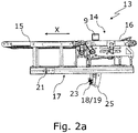
- FIG 2a shows a side view of a first embodiment of the feed module 13.
- the feed module 13 comprises a weighing device 14 for determining the respective weight of the packaged goods 9 and a feed belt 15 for feeding a packaged goods 9 to be packaged in the transport direction X to a film packaging device in the packaging machine 10 (see Figures 1a , 1b ).
- the weighing device 14 has a weighing belt 16 for conveying the packaged goods 9 from the weighing device 14 to the feed belt 15 in the transport direction X.
- the weighing device 14 and the feed belt 15 are connected via a common carrier 17 to form the feed module 13 .
- the feed module 13 is detachably connected to the housing 11 of the packaging machine 10 via a plug 18 as a common fastening means 19 of the weighing device 14 and the feed belt 15 .
- the plug 18 is plugged into a corresponding plug socket 20 of the housing (see Figure 4a ), in particular detachable without tools, locked.
- the plug 18 is primarily used to supply current or voltage.
- Guide pins 21 of the feed module 13 engage in corresponding guide pin receptacles 22 (see Figure 4a ) of the housing 11 for guiding the feed module 13 when the feed module 13 is pushed into the housing 11 .
- a guide pin 23 is used for insertion into a corresponding guide pin receptacle 24 (see Figure 4a ) of the housing 11 for guiding the plug 18 when it is pushed into the socket 20.
- the infeed module 13 can be placed on a protective bracket 25 when it has been removed from the packaging machine 10 .
- FIG. 2b shows a plan view of the feed module 13 according to FIG Figure 2a .
- the feed belt 15 has conveyor belts 26 arranged next to one another for transporting the packaged goods 9 (see FIG Figure 2a ), which in particular is in a lifting table 27 of the packaging machine 10 (see Figure 4a ) intervene.
- a sliding plate 28 is arranged between the infeed belt 15 and the weighing belt 16 .
- a protective plate 29 is arranged on the weighing belt 16 to protect the weighing belt 16 and the interior of the packaging machine (not shown here) from external influences, the protective plate 29 being detachably fastened to the weighing belt 16 by means of knurled screws 45 .
- the protective plate 29 also serves to protect operating personnel and also defines the reachable support area for the packaged goods 9 on the weighing belt 16.
- Figure 2c shows a first embodiment of the feed module 13 in a view looking in the direction of the housing 11 (see Fig. 1a ) when inserting the feed module 13 side facing.
- First sliding surfaces 30 of the feed module serve to rest on a bearing surface 31 (see Figure 4a ) of the housing 11 when the feed module 13 is pushed into the housing 11.
- Locking bolts 32 are fastened to the protective bar 25, which fit into corresponding locking bolt receptacles 33 (see Figure 4c ) of guide elements 34 engage on the housing 11 of the packaging machine, the locking bolts 32 having a spring mechanism (not shown here) for unlocking and/or locking the feed module 13 on the housing 11 of the packaging machine 10.
- Fig. 2d 13 shows a second embodiment of the feed module 13' in a view looking in the direction of the side facing the housing 11 when the feed module is inserted.
- the second embodiment of the feeder module 13' has all the features of the first embodiment (see Figure 2c ) on.
- the feed module 13' in the second embodiment includes second sliding surfaces 35 for contact with corresponding slide rails 36 of the housing 11 (see FIG Figure 4b ).
- FIG. 2e 13 shows the feeding module 13 in the first embodiment according to FIG Figure 2a in a view looking towards the side facing the outside in the assembled state of the feed module 13.
- the weighing device 14 has a load cell 37 which is connected to the weighing belt 16 in order to weigh the packaged goods 9 (see Figure 2a ) on the weighing belt 16 to be determined. Also shown are the protective bar 25 with the locking bolts 32, the protective plate 29 and the first sliding surfaces 30.
- Fig. 2f shows the feed module 13 in a view from below in the assembled state of the feed module 13. Shown are, among other things, the conveyor belts 26 of the feed belt 15 and the guide bolts 21.
- FIG 3a shows a first embodiment of a removable hood 38 for covering the feed module 13 (see FIG Figure 2a ).
- the hood 38 has eyelets 39 for detachable hanging in corresponding eyelet receptacles 44 (see Figure 4a , for example in the form of screws) of the housing 11 (see Fig. 1a ) of the packaging machine 10.
- the hood 38 has a magnet 40 which is controlled by a magnetic sensor 41 (see Figure 4a ) on the housing 11 can be detected to indicate that the hood 38 is attached to the housing 11 of the packaging machine 10.
- the hood 38 has a rear cover plate 42 which faces away from the eyelets 39 and the magnetic sensor 41 .
- the cover plate 42 covers the weighing belt 16 in the vertical direction (see Figure 2a ) to protect the latter as well as the interior of the packaging machine 10 (not shown here) from external influences and dirt.
- the rear cover plate 42 between the side cover plates 42a, 42b is designed to be lower than the side cover plates 42a, 42b, so that when the hood 38 is in the installed state, the cover plate 42 only extends below the weighing belt 16 (see Fig Figure 2a ) enough.
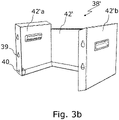
- Figure 3b shows a second embodiment of the removable hood 38' with the eyelets 39 and the magnet 40.
- the rear cover plate 42' between the side cover plates 42'a, 42'b is again lower than the side cover plates 42'a, 42'b, so that the cover plate 42' when the hood 38' is in the assembled state, in particular only up to below the weighing belt 16 (see Figure 2a ) enough.
- the cover plates 42; 42' protect the interior of the packaging machine (see Fig. 1a ), but enable an automatic feeding of packaged goods 9 onto the weighing belt 16 (see Figure 2a ) and to the packaging machine 10.
- the packaged goods 9 are guided to the weighing belt 16 via a further conveyor belt (not shown in the drawing).
- Figure 4a shows a first embodiment of the housing 11.
- the receptacle for the feed module 13 (see Figure 2a ) has a bearing surface 31 for the first sliding surfaces 30 (see Figure 2a ) of the feed module 13.
- a lifting table 27 has columns 43 for transporting the respective packaged goods 9 (see Figure 2a ) versus the film (not shown here), which is then folded around the packaged goods 9 by a folding mechanism (also not shown here).
- the conveyor belts 26 are arranged between the columns 43 of the lifting table 27 in the assembled state of the feed module 13 . They convey the packaged goods 9 onto the columns 43, which then transport the packaged goods 9 against the film.
- Guide elements 34 on the housing 11 of the packaging machine 10 serve to guide the feed module 13 , with the guide elements 34 protruding from the housing 11 of the packaging machine 10 .
- Guide bolt mounts 22 are used to guide the guide bolts 21 (see Figure 2a ) of the feed module 13.
- a socket 20 in the housing 11 is used to accommodate the plug 18 (see Figure 2c ).
- a guide pin receptacle 24 is formed.
- the eyelet receptacles 44 into which the eyelets 39 of the hood 38 are hung.
- a magnetic sensor 41 detects the magnet 40 (see Figure 3a ) on the hood 38 when the hood 38 is placed on the housing 11.
- Figure 4b shows a second embodiment of the housing 11' with a second embodiment of the receptacle 12'.
- the receptacle 12' has slide rails 36, along which the corresponding second sliding surfaces 35 of the feed module 13' in the second embodiment slide when the feed module 13' is pushed in.
- the slide rails 36 are formed on the bearing surface 31 of the housing 11 .
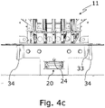
- Figure 4c shows the housing 11 with the socket 20 and the guide pin receptacle 24 and the guide elements 34 on the housing 11 in a detailed view.
- the guide elements 34 have locking bolt receptacles 33 for the locking bolts 32 of the feed module 13 (see Figure 2c ) on.
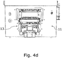
- Figure 4d shows the housing 11 with the inserted feed module 13 without the hood 38 (see Figure 3a ).
Landscapes
- Engineering & Computer Science (AREA)
- Mechanical Engineering (AREA)
- Quality & Reliability (AREA)
- Auxiliary Devices For And Details Of Packaging Control (AREA)
Abstract
Description
- Die Erfindung betrifft eine Verpackungsmaschine zum Verpacken von Verpackungsgütern mittels einer Folie, mit einem Gehäuse, mit einem Zuführband zur Zuführung eines zu verpackenden Verpackungsgutes in einer Transportrichtung zu einer Folienverpackungseinrichtung in der Verpackungsmaschine, sowie mit einer Wägeeinrichtung zur Ermittlung des jeweiligen Gewichts des Verpackungsgutes.
- Eine Verpackungsmaschine mit diesen Merkmalen ist an sich bekannt beispielsweise aus der
EP 3 611 100 B1 (= Referenz [1]). - In der
EP 3 587 289 B1 (= Referenz [2]) ist eine Folientransportvorrichtung für eine Verpackungsmaschine offenbart, bei der Folien bei der Zuführung an die Folientransportvorrichtung zwischen Transportringe eingeführt werden und unter Haftreibung in Kontakt mit den Transportringen treten. Die Transportringe können die Folien weiterbefördern, bis sie von Transportriemen übernommen werden. Dadurch wird die Stabilität des Prozesses der Einführung der Folie in die Folientransportvorrichtung erhöht. - Aus der
EP 3 587 283 B1 (= Referenz [3]) ist eine Verpackungsmaschine mit zwei Riemenfördereinrichtungen und mit einer Führungsplatte bekannt, die mehrere Ausnehmungen aufweist, wobei eine der Riemenfördereinrichtungen in die Ausnehmungen einführbar sind, sodass die Verpackungsmaschine relativ einfach auf Folienrollen verschiedener Breite umrüstbar ist. - In der
EP 3 613 676 B1 (= Referenz [4]) ist eine Verpackungsmaschine mit einer Messereinrichtung beschrieben, die mit einem Rückholmechanismus versehen ist, der mit der Überführung der Messereinrichtung aus einer Ruhestellung in eine ausgefahrene Stellung aktivierbar ist. Der Rückholmechanismus bewirkt eine Rückholung der Messereinrichtung ohne Einwirkung des Antriebs der Messereinrichtung, vorzugsweise selbsttätig. - Die eingangs zitierte Referenz [1] offenbart eine Verpackungsmaschine, bei welcher Folien durch linke, rechte und hintere Faltungsplatten bzw. Schieber zur Unterseite von Schale hin gefaltet werden. Sowohl die seitlichen Schieber als auch der rückwärtige Schieber sind über mindestens ein Dämpfungselement am Maschinenrahmen befestigt. Das Dämpfungselement ist so gestaltet, dass es eine Übertragung von mechanischen Schwingungen der seitlichen Schieber und des rückwärtigen Schiebers auf den Maschinenrahmen verhindert oder zumindest abschwächt. Auch bei hohen Verpackungsgeschwindigkeiten wird dadurch der Wägewert von Verpackungsgütern nicht oder nur in einem vertretbaren Toleranzbereich verfälscht.
- Bei den bekannten Verpackungsmaschinen ist der Innenraum, in dem der Verpackungsvorgang von Verpackungsgütern in Folie stattfindet, vergleichsweise schwer zu reinigen. Aufgabe der Erfindung ist es demgegenüber, eine Verpackungsmaschine der eingangs definierten Art bereitzustellen, bei der mit möglichst unaufwändigen Modifikationen der Innenraum besonders leicht gereinigt werden kann, insbesondere im Bereich der Produktzuführung.
- Diese Aufgabe wird auf technisch äußerst einfache und überraschend wirkungsvolle Weise bei einer gattungsgemäßen Verpackungsmaschine der oben beschriebenen Art erfindungsgemäß dadurch gelöst, dass die Wägeeinrichtung ein Wägeband zur Beförderung des Verpackungsgutes von der Wägeeinrichtung zu dem Zuführband in Transportrichtung aufweist, und dass die Wägeeinrichtung mit dem Zuführband fest verbunden ist, wobei die Wägeeinrichtung und das Zuführband gemeinsam ein von dem Gehäuse abnehmbares Zuführmodul bilden, und wobei das abnehmbare Zuführmodul ein gemeinsames Befestigungsmittel zur lösbaren Befestigung an dem Gehäuse aufweist, so dass die Wägeeinrichtung und das Zuführband zusammen ein von dem Gehäuse einfach abnehmbares und auch leicht am Stück wieder anmontierbares, kompaktes Zuführmodul bilden.
- Bei der erfindungsgemäßen Modifikation wird nicht nur das Wägeband aus der Maschine herausgenommen, sondern das Wägeband zusammen mit den Förderriemen, die normalerweise bis in den Hubtisch hineinragen.
- Viele Maschinen aus dem Stand der Technik kennen jedoch diese Unterscheidung gar nicht, sondern sie besitzen nur ein Riemenband, auf dem dann auch gewogen wird.
- Die erfindungsgemäß modifizierte Wägeeinrichtung weist neben dem vom Zuführband getrennten Wägeband typischerweise eine Wägezelle auf, die mit dem Wägeband verbunden ist und mit welcher das Gewicht des auf dem Wägeband liegenden Verpackungsgutes bestimmt wird.
- In der Folienverpackungseinrichtung wird das Verpackungsgut mit Folie umwickelt. Unter dem Begriff Zuführmodul wird insbesondere ein Bauteil der Verpackungsmaschine verstanden, dass sowohl das Wiegen eines Verpackungsgutes als auch das Zuführen des Verpackungsgutes von dem Außenraum in das Innere der Verpackungsmaschine zum Verpacken des Verpackungsgutes in Folie ermöglicht. Um einen Zugang zu dem Innenraum der Verpackungsmaschine zu erhalten, ist es vorteilhafterweise bereits ausreichend, das Zuführmodul von dem Gehäuse der Verpackungsmaschine zu lösen. Anschließend kann der Innenraum, insbesondere die Produktzuführung, gereinigt werden. Das Gehäuse weist typischerweise eine Aufnahme auf, in die das Zuführmodul eingesetzt wird.
- Eine vorteilhafte Ausführungsform der erfindungsgemäßen Verpackungsmaschine zeichnet sich dadurch aus, dass die Wägeeinrichtung und das Zuführband einen gemeinsamen Träger zur Ausbildung des Zuführmoduls aufweisen. Der gemeinsame Träger ist vorzugweise mit Streben, Rohren und/oder als Rahmen ausgebildet. Die Wägeeinrichtung und das Zuführband sind mit dem gemeinsamen Träger vorzugsweise fest verbunden. Der gemeinsame Träger verleiht dem Zuführmodul eine hohe Stabilität.
- Eine weitere Ausführungsform ist dadurch gekennzeichnet, dass das Befestigungsmittel zu einer ohne Werkzeuge lösbaren Befestigung des Zuführmoduls an dem Gehäuse ausgebildet ist. Hierzu kann das Befestigungsmittel elastische Elemente umfassen, die von Hand verbiegbar sind. Durch ein solches Befestigungsmittel kann das Zuführmodul besonders einfach und schnell von dem Gehäuse der Verpackungsmaschine gelöst werden.
- Bei einer Klasse von weiteren vorteilhaften Ausführungsformen der Erfindung umfasst das Zuführmodul erste Gleitflächen zur Auflage auf einer Auflagefläche des Gehäuses beim Einschieben des Zuführmoduls in das Gehäuse. Insbesondere umfasst die Aufnahme in einer ersten Ausgestaltung die Aufnahmefläche. Die ersten Gleitflächen sind vorzugsweise als Schienen ausgestaltet, auf denen das Zuführmodul gleitet.
- Eine Weiterbildung der vorgenannten Ausführungsformen zeichnet sich dadurch aus, dass auf der Auflagefläche des Gehäuses Gleitschienen zur Anlage an korrespondierenden zweiten Gleitflächen des Zuführmoduls ausgebildet sind. Insbesondere umfasst die Aufnahme in einer zweiten Ausgestaltung die Gleitschienen auf der Aufnahmefläche. Die zweiten Gleitflächen stehen insbesondere senkrecht zu den ersten Gleitflächen und sind vorzugsweise als Metallschienen ausgebildet.
- Eine weitere vorteilhafte Ausbildung der Folientransportvorrichtung ist dadurch gekennzeichnet, dass das Zuführmodul Führungsbolzen aufweist, die in korrespondierende Führungsbolzen-Aufnahmen des Gehäuses zur Führung des Zuführmoduls bei einem Einschieben des Zuführmoduls in das Gehäuse eingreifen. Die insbesondere rohrförmigen, im montierten Zustand des Zuführmoduls seitlich an dem Zuführmodul angeordneten Führungsbolzen dienen der Ausrichtung des Zuführmoduls beim Einschieben desselben in das Gehäuse der Verpackungsmaschine.
- Bei einer weiteren Ausführungsform der erfindungsgemäßen Verpackungsmaschine weist das Zuführmodul einen Stecker zum Einstecken in eine korrespondierende Steckerbuchse im Gehäuse auf, um das Zuführmodul an dem Gehäuse zu befestigen, wobei der Stecker vorzugsweise einen Führungsstift zum Einschieben in eine korrespondierende Führungsstift-Aufnahme des Gehäuses aufweist. Der Stecker umfasst insbesondere elastische Elemente, die beim Einschieben des Zuführmoduls in das Gehäuse der Verpackungsmaschine in der Steckerbuchse verrasten. Hierdurch wird auf einfache Weise das Zuführmodul am Gehäuse befestigt.
- Bei geometrisch umgekehrt angeordneten, in ihrer Wirkung aber äquivalenten Ausführungsformen kann das Zuführmodul eine Führungsstift-Aufnahme in Form einer Steckerbuchse aufweisen. Das Gehäuse weist dann einen dazu korrespondierenden Stecker zum Einstecken in die Steckerbuchse des Zuführmoduls auf. Bei beiden Ausführungsformen kann der Stecker einer Strom- oder Spannungszuführung dienen.
- Eine vorteilhafte Ausgestaltung der erfindungsgemäßen Verpackungsmaschine ist durch eine abnehmbare Haube zur Abdeckung des Zuführmoduls gekennzeichnet, wobei die Haube insbesondere Ösen zum lösbaren Einhängen in Ösen-Aufnahmen des Gehäuses der Verpackungsmaschine aufweist. Die Haube schützt das Zuführmodul und den Innenraum der Verpackungsmaschine vor Einwirkungen von außen sowie vor Verschmutzung. Die Haube weist insbesondere senkrecht aufeinander stehende Wände auf, die mindestens die Wägeeinrichtung an drei Seiten umgreifen, wenn die Haube an dem Zuführmodul angeordnet ist.
- Eine Weiterentwicklung der vorgenannten Ausgestaltung zeichnet sich dadurch aus, dass am Gehäuse ein Sensor, insbesondere ein Magnetsensor, vorgesehen ist, mit welchem detektiert werden kann, ob die Haube aktuell am Gehäuse der Verpackungsmaschine befestigt ist oder eben nicht.
- An der Haube ist vorzugsweise ein Gegenstück zu dem Sensor angeordnet, das vom Sensor immer dann detektiert wird, wenn die Haube am Gehäuse angeordnet ist. An der Haube befindet sich insbesondere ein Magnet, der von einem Magnetsensor detektiert wird, wenn die Haube an dem Gehäuse angebracht ist. Die Verpackungsmaschine beendet vorzugsweise automatisch den Verpackungsvorgang, sobald die Haube von dem Gehäuse entfernt wird.
- Eine bevorzugte Ausführungsform der erfindungsgemäßen Verpackungsmaschine ist durch Führungselemente an dem Gehäuse der Verpackungsmaschine zur Führung des Zuführmoduls gekennzeichnet, wobei die Führungselemente von dem Gehäuse der Verpackungsmaschine abstehen. Die Führungselemente sind insbesondere als Schienen ausgebildet, die senkrecht von dem Gehäuse der Verpackungsmaschine abstehen. Das Zuführmodul gleitet beim Einschieben zwischen den Führungselementen entlang, die an dem Zuführmodul anliegen. Die Führungselemente richten das Zuführmodul beim Einschieben aus. Dadurch stellen die Führungselemente ein korrektes Einschieben des Zuführmoduls sicher.
- Eine Weiterentwicklung dieser Ausführungsform ist gekennzeichnet durch Rastbolzen des Zuführmoduls zum Eingreifen in eine jeweils korrespondierende Rastbolzen-Aufnahme der Führungselemente am Gehäuse der Verpackungsmaschine. Die Rastbolzen dienen zur Sicherung des Moduls im Führungselement und weisen vorzugsweise einen Federmechanismus zum Entriegeln und/oder Verriegeln des Zuführmoduls an dem Gehäuse der Verpackungsmaschine auf.
- Das Verriegeln beim Einschieben des Zuführmoduls erfolgt vorzugsweise automatisch. Dies kann insbesondere durch die Federmechanismen der Rastbolzen bewirkt werden. Die Rastbolzen-Aufnahmen sind insbesondere als Öffnungen in den Führungselementen ausgebildet.
- Vorteilhaft ist bei Ausführungsformen der Erfindung ein Schutzbügel zur Ablage des Zuführmoduls, auf welchem insbesondere das Zuführmodul abgestellt werden kann, wenn es aus der Verpackungsmaschine entfernt wurde. Der Schutzbügel ist im montierten Zustand des Zuführmoduls insbesondere unterhalb der Wägeeinrichtung am Zuführmodul angeordnet. Der Schutzbügel weist vorzugsweise ein U-förmiges Profil auf. Das Zuführmodul wird bevorzugt auf dem Schutzbügel und einer hinteren Kante des Zuführmoduls abgestellt. An dem Schutzbügel sind normalerweise die vorgenannten Rastbolzen ausgebildet.
- Bevorzugt weist das Zuführband der erfindungsgemäßen Verpackungsmaschine nebeneinander angeordnete Förderriemen zum Transport des Verpackungsgutes auf. Diese können insbesondere in einen Hubtisch der Verpackungsmaschine eingreifen.
- Der Hubtisch weist insbesondere Säulen zum Transport des Verpackungsgutes gegen die Folie auf, wobei die Förderriemen im montierten Zustand des Zuführbandes zwischen den Säulen angeordnet sind. Das Verpackungsgut wird von den Förderriemen auf den Hubtisch befördert, der das Verpackungsgut anschließend für den Faltungsvorgang gegen die Folie bewegt.
- Eine vorteilhafte Ausführungsform der erfindungsgemäßen Verpackungsmaschine ist dadurch gekennzeichnet, dass zum Transport des Verpackungsgutes vom Wägeband zum Zuführband ein Gleitblech zwischen dem Zuführband und dem Wägeband angeordnet ist. Das Gleitblech liegt mit einem Ende am Zuführband und mit dem anderen Ende am Wägeband an. Das Verpackungsgut gleitet bei seiner Beförderung vom Wägeband zum Zuführband über dieses Gleitblech.
- Eine bevorzugte Variante der Verpackungsmaschine weist ein Schutzblech für das Wägeband auf, wobei das Schutzblech insbesondere durch Rändelschrauben lösbar am Wägeband befestigt ist. Das Schutzblech schützt das Wägeband und das Innere der Verpackungsmaschinen vor äußeren Einwirkungen sowie vor Verschmutzung. Es kann einfach entfernt werden, um die Maschine von einem Betriebsmodus mit manuellem Einlegen der Verpackungen zu einer automatischen Beschickung des Wägebandes mit Verpackungsgütern umzurüsten.
- Weitere Merkmale und Vorteile der Erfindung ergeben sich aus der nachfolgenden detaillierten Beschreibung von Ausführungsbeispielen der Erfindung anhand der Figuren der Zeichnung, die erfindungswesentliche Einzelheiten zeigt, sowie aus den Ansprüchen. Die einzelnen Merkmale können je einzeln für sich oder zu mehreren in beliebigen Kombinationen bei Varianten der Erfindung verwirklicht sein.
- In der schematischen Zeichnung sind Ausführungsbeispiele der Erfindung dargestellt, welche in der nachfolgenden Beschreibung näher erläutert werden.
- Es zeigen:
- Fig. 1a
- eine isometrische Ansicht einer Verpackungsmaschine zum Verpacken von Verpackungsgütern mittels einer Folie mit einem erfindungsgemäßen Zuführmodul;
- Fig. 1b
- eine isometrische Ansicht der Verpackungsmaschine aus
Fig. 1a ohne das Zuführmodul; - Fig. 2a
- eine Seitenansicht einer ersten Ausführungsform des erfindungsgemäßen Zuführmoduls;
- Fig. 2b
- eine Draufsicht auf das Zuführmodul nach
Fig. 2a ; - Fig. 2c
- die erste Ausführungsform des Zuführmoduls in einer Ansicht in Richtung auf die dem Gehäuse der Verpackungsmaschine zugewandte Seite;
- Fig. 2d
- eine zweite Ausführungsform des Zuführmoduls in einer Ansicht auf die dem Gehäuse zugewandte Seite;
- Fig. 2e
- das Zuführmodul in der ersten Ausführungsform in einer Ansicht auf die dem Außenraum zugewandte Seite;
- Fig. 2f
- das Zuführmodul in einer Ansicht von unten;
- Fig. 3a
- eine erste Ausführungsform einer abnehmbaren Haube zur Abdeckung des Zuführmoduls;
- Fig. 3b
- eine zweite Ausführungsform der abnehmbaren Haube;
- Fig. 4a
- eine erste Ausführungsform des Gehäuses der erfindungsgemäßen Verpackungsmaschine;
- Fig. 4b
- eine zweite Ausführungsform des Gehäuses;
- Fig. 4c
- das Gehäuse mit einer Steckerbuchse in einer Detailansicht; und
- Fig. 4d
- das Gehäuse mit eingesetztem Zuführmodul ohne Haube.
-
Fig. 1a zeigt eine isometrische Ansicht einer Verpackungsmaschine 10 zum Verpacken von Verpackungsgütern (hier nicht gezeigt) mittels einer Folie. Die Maschine verfügt über ein Gehäuse 11. In einer Aufnahme 12 des Gehäuses 11 befindet sich ein Zuführmodul 13 zur Zuführung von Verpackungsgütern in einer Transportrichtung X. -
Fig. 1b zeigt die Verpackungsmaschine 10 ohne das Zuführmodul 13. -
Fig. 2a zeigt eine Seitenansicht einer ersten Ausführungsform des Zuführmoduls 13. Das Zuführmodul 13 umfasst eine Wägeeinrichtung 14 zur Ermittlung des jeweiligen Gewichts des Verpackungsgutes 9 und ein Zuführband 15 zur Zuführung eines zu verpackenden Verpackungs-gutes 9 in der Transportrichtung X zu einer Folienverpackungs-einrichtung in der Verpackungsmaschine 10 (sieheFiguren 1a ,1b ). - Die Wägeeinrichtung 14 weist ein Wägeband 16 zur Beförderung des Verpackungsgutes 9 von der Wägeeinrichtung 14 zu dem Zuführband 15 in Transportrichtung X auf. Die Wägeeinrichtung 14 und das Zuführband 15 sind zur Ausbildung des Zuführmoduls 13 über einen gemeinsamen Träger 17 verbunden.
- Das Zuführmodul 13 wird über einen Stecker 18 als gemeinsames Befestigungsmittel 19 der Wägeeinrichtung 14 und des Zuführbandes 15 mit dem Gehäuse 11 der Verpackungsmaschine 10 lösbar verbunden. Dazu wird der Stecker 18 in einer korrespondierenden Steckerbuchse 20 des Gehäuses (siehe
Fig. 4a ), insbesondere werkzeugfrei lösbar, verrastet. Der Stecker 18 dient in erster Linie der Strom- bzw. Spannungszuführung. - Führungsbolzen 21 des Zuführmoduls 13 greifen in korrespondierende Führungsbolzen-Aufnahmen 22 (siehe
Fig. 4a ) des Gehäuses 11 zur Führung des Zuführmoduls 13 bei einem Einschieben des Zuführmoduls 13 in das Gehäuse 11 ein. Ein Führungsstift 23 dient dem Einschieben in eine korrespondierende Führungsstift-Aufnahme 24 (sieheFig. 4a ) des Gehäuses 11 zur Führung des Steckers 18 beim Einschieben in die Steckerbuchse 20. - Das Zuführmodul 13 kann auf einem Schutzbügel 25 abgestellt werden, wenn es aus der Verpackungsmaschine 10 entfernt wurde.
-
Fig. 2b zeigt eine Draufsicht auf das Zuführmodul 13 gemäßFig. 2a . Das Zuführband 15 weist nebeneinander angeordnete Förderriemen 26 zum Transport des Verpackungsgutes 9 (sieheFig. 2a ) auf, die insbesondere in einen Hubtisch 27 der Verpackungsmaschine 10 (sieheFig. 4a ) eingreifen. - Zum Transport des Verpackungsgutes 9 vom Wägeband 16 zum Zuführband 15 ist ein Gleitblech 28 zwischen dem Zuführband 15 und dem Wägeband 16 angeordnet.
- An dem Wägeband 16 ist ein Schutzblech 29 zum Schutz des Wägebands 16 und des Innenraums der Verpackungsmaschine (hier nicht gezeigt) vor äußeren Einwirkungen angeordnet, wobei das Schutzblech 29 durch Rändelschrauben 45 lösbar an dem Wägeband 16 befestigt ist. Das Schutzblech 29 dient auch dem Schutz von Bedienungspersonal und definiert zudem den erreichbaren Auflagebereich für das Verpackungsgut 9 auf den Wägeband 16.
-
Fig. 2c zeigt eine erste Ausführungsform des Zuführmoduls 13 in einer Ansicht mit Blickrichtung auf die dem Gehäuse 11 (sieheFig. 1a ) beim Einschieben des Zuführmoduls 13 zugewandte Seite. Erste Gleitflächen 30 des Zuführmoduls dienen zur Auflage auf einer Auflagefläche 31 (sieheFig. 4a ) des Gehäuses 11 beim Einschieben des Zuführmoduls 13 in das Gehäuse 11. - An dem Schutzbügel 25 sind Rastbolzen 32 befestigt, die in korrespondierende Rastbolzen-Aufnahmen 33 (siehe
Fig. 4c ) von Führungselementen 34 an dem Gehäuse 11 der Verpackungsmaschine eingreifen, wobei die Rastbolzen 32 über einen Federmechanismus (hier nicht gezeigt) zum Entriegeln und/oder Verriegeln des Zuführmoduls 13 an dem Gehäuse 11 der Verpackungsmaschine 10 verfügen. -
Fig. 2d zeigt eine zweite Ausführungsform des Zuführmoduls 13' in einer Ansicht mit Blickrichtung auf die dem Gehäuse 11 beim Einschieben des Zuführmoduls zugewandte Seite. Die zweite Ausführungsform des Zuführmoduls 13' weist alle Merkmale der ersten Ausführungsform (sieheFig. 2c ) auf. Zusätzlich umfasst hier das Zuführmodul 13' in der zweiten Ausführungsform zweite Gleitflächen 35 zur Anlage an korrespondierenden Gleitschienen 36 des Gehäuses 11 (sieheFig. 4b ). -
Fig. 2e zeigt das Zuführmodul 13 in der ersten Ausführungsform gemäßFig. 2a in einer Ansicht mit Blickrichtung auf die dem Außenraum zugewandte Seite im montierten Zustand des Zuführmoduls 13. Die Wägeeinrichtung 14 weist eine Wägezelle 37 auf, die mit dem Wägeband 16 verbunden ist, um das Gewicht des Verpackungsgutes 9 (sieheFig. 2a ) auf dem Wägeband 16 zu bestimmen. Gezeigt sind auch der Schutzbügel 25 mit den Rastbolzen 32, das Schutzblech 29 sowie die ersten Gleitflächen 30. -
Fig. 2f zeigt das Zuführmodul 13 in einer Ansicht von unten im montierten Zustand des Zuführmoduls 13. Dargestellt sind unter anderem die Förderriemen 26 des Zuführbandes 15 sowie die Führungsbolzen 21. -
Fig. 3a zeigt eine erste Ausführungsform einer abnehmbaren Haube 38 zur Abdeckung des Zuführmoduls 13 (sieheFig. 2a ). Die Haube 38 weist Ösen 39 zum lösbaren Einhängen in entsprechende Ösen-Aufnahmen 44 (sieheFig. 4a , beispielsweise in Form von Schrauben) des Gehäuses 11 (sieheFig. 1a ) der Verpackungsmaschine 10 auf. - Die Haube 38 verfügt über einen Magneten 40, der von einem Magnetsensor 41 (siehe
Fig. 4a ) an dem Gehäuse 11 detektiert werden kann, um anzuzeigen, dass die Haube 38 am Gehäuse 11 der Verpackungsmaschine 10 befestigt ist. - Außerdem weist die Haube 38 eine hintere Abdeckplatte 42 auf, die von den Ösen 39 und dem Magnetsensor 41 abgewandt ist. Die Abdeckplatte 42 überdeckt im montierten Zustand der Haube 38 in vertikaler Richtung das Wägeband 16 (siehe
Fig. 2a ), um letzteres sowie auch den Innenraum der Verpackungsmaschine 10 (hier nicht gezeigt) vor äußeren Einwirkungen und Verschmutzung zu schützen. Die hintere Abdeckplatte 42 zwischen den seitlichen Abdeckplatte 42a, 42b ist niedriger als die seitlichen Abdeckplatten 42a, 42b ausgebildet, sodass die Abdeckplatte 42 im montierten Zustand der Haube 38 insbesondere nur bis unterhalb des Wägebands 16 (sieheFig. 2a ) reicht. -
Fig. 3b zeigt eine zweite Ausführungsform der abnehmbaren Haube 38' mit den Ösen 39 und dem Magneten 40. Die hintere Abdeckplatte 42' zwischen den seitlichen Abdeckplatte 42'a, 42'b ist wiederum niedriger als die seitlichen Abdeckplatten 42'a, 42'b ausgebildet, sodass die Abdeckplatte 42' im montierten Zustand der Haube 38' insbesondere nur bis unterhalb des Wägebands 16 (sieheFig. 2a ) reicht. - Die Abdeckplatten 42; 42' schützen den Innenraum der Verpackungsmaschine (siehe
Fig. 1a ), ermöglichen aber eine automatische Zuführung von Verpackungsgütern 9 auf das Wägeband 16 (sieheFig. 2a ) und zu der Verpackungsmaschine 10. Die Verpackungsgüter 9 werden über ein weiteres (in der Zeichnung nicht dargestelltes) Förderband zum Wägeband 16 hingeführt. -
Fig. 4a zeigt eine erste Ausführungsform des Gehäuses 11. Die Aufnahme für das Zuführmodul 13 (sieheFig. 2a ) weist eine Auflagefläche 31 für die ersten Gleitflächen 30 (sieheFig. 2a ) des Zuführmoduls 13 auf. Ein Hubtisch 27 verfügt über Säulen 43 zur Beförderung des jeweiligen Verpackungsgutes 9 (sieheFig. 2a ) gegen die Folie (hier nicht gezeigt), die anschließend durch einen Faltmechanismus (hier ebenfalls nicht gezeigt) um das Verpackungsgut 9 gefaltet wird. - Die Förderriemen 26 (siehe
Fig. 2b ) sind im montierten Zustand des Zuführmoduls 13 zwischen den Säulen 43 des Hubtisches 27 angeordnet. Sie befördern das Verpackungsgut 9 auf die Säulen 43, die anschließend das Verpackungsgut 9 gegen die Folie transportieren. - Führungselemente 34 am Gehäuse 11 der Verpackungsmaschine 10 dienen der Führung des Zuführmoduls 13, wobei die Führungselemente 34 von dem Gehäuse 11 der Verpackungsmaschine 10 abstehen.
- Führungsbolzen-Aufnahmen 22 dienen der Führung der Führungsbolzen 21 (siehe
Fig. 2a ) des Zuführmoduls 13. Eine Steckerbuchse 20 in dem Gehäuse 11 dient der Aufnahme des Steckers 18 (sieheFig. 2c ). Zur Führung des Führungsstifts 23 (sieheFig. 2a ) an dem Stecker 18 ist in dem Gehäuse 11 eine Führungsstift-Aufnahme 24 ausgebildet. Gezeigt sind auch die Ösen-Aufnahmen 44, in welche die Ösen 39 der Haube 38 eingehängt werden. Ein Magnetsensor 41 detektiert den Magneten 40 (sieheFig. 3a ) an der Haube 38, wenn die Haube 38 an dem Gehäuse 11 angeordnet ist. -
Fig. 4b zeigt eine zweite Ausführungsform des Gehäuses 11' mit einer zweiten Ausführungsform der Aufnahme 12'. Die Aufnahme 12' weist bei dieser zweiten Ausgestaltung Gleitschienen 36 auf, an denen die korrespondierenden zweiten Gleitflächen 35 des Zuführmoduls 13' in der zweiten Ausführungsform beim Einschieben des Zuführmoduls 13' entlanggleiten. Die Gleitschienen 36 sind auf der Auflagefläche 31 des Gehäuses 11 ausgebildet. -
Fig. 4c zeigt das Gehäuse 11 mit der Steckerbuchse 20 und der Führungsstift-Aufnahme 24 sowie den Führungselementen 34 an dem Gehäuse 11 in einer Detailansicht. Die Führungselemente 34 weisen Rastbolzen-Aufnahmen 33 für die Rastbolzen 32 des Zuführmoduls 13 (sieheFig. 2c ) auf. -
Fig. 4d zeigt das Gehäuse 11 mit dem eingesetzten Zuführmodul 13 ohne die Haube 38 (sieheFig. 3a ). -
- 9
- Verpackungsgut
- 10
- Verpackungsmaschine
- 11,11'
- Gehäuse
- 12,12'
- Aufnahme
- 13,13'
- Zuführmodul
- 14
- Wägeeinrichtung
- 15
- Zuführband
- 16
- Wägeband
- 17
- gemeinsamer Träger
- 18
- Stecker
- 19
- gemeinsames Befestigungsmittel
- 20
- Steckerbuchse
- 21
- Führungsbolzen
- 22
- Führungsbolzen-Aufnahmen
- 23
- Führungsstift
- 24
- Führungsstift-Aufnahme
- 25
- Schutzbügel
- 26
- Förderriemen
- 27
- Hubtisch
- 28
- Gleitblech
- 29
- Schutzblech
- 30
- erste Gleitflächen
- 31
- Auflagefläche
- 32
- Rastbolzen
- 33
- Rastbolzen-Aufnahmen
- 34
- Führungselemente
- 35
- zweite Gleitflächen
- 36
- Gleitschiene
- 37
- Wägezelle
- 38
- Haube
- 39
- Ösen
- 40
- Magnet
- 41
- Magnetsensor
- 42; 42'
- hintere Abdeckplatte
- 42a,42b; 42'a,42'b
- seitliche Abdeckplatten
- 43
- Säulen
- 44
- Ösen-Aufnahmen
- 45
- Rändelschrauben
- Für die Beurteilung der Patentfähigkeit in Betracht gezogene Publikationen:
- [1]
EP 3 611 100 B1 - [2]
EP 3 587 289 B1 - [3]
EP 3 587 283 B1 - [4]
EP 3 613 676 B1
Claims (15)
- Verpackungsmaschine (10) zum Verpacken von Verpackungsgütern (9) mittels einer Folie, mit einem Gehäuse (11, 11') und mit einem Zuführband (15) zur Zuführung eines zu verpackenden Verpackungsgutes (9) in einer Transportrichtung (X) zu einer Folienverpackungseinrichtung in der Verpackungsmaschine (10),
sowie mit einer Wägeeinrichtung (14) zur Ermittlung des jeweiligen Gewichts des Verpackungsgutes (9),
dadurch gekennzeichnet,
dass die Wägeeinrichtung (14) ein Wägeband (16) zur Beförderung des Verpackungsgutes (9) von der Wägeeinrichtung (14) zu dem Zuführband (15) in Transportrichtung (X) aufweist, und dass die Wägeeinrichtung (14) mit dem Zuführband (15) fest verbunden ist, wobei die Wägeeinrichtung (14) und das Zuführband (15) gemeinsam ein von dem Gehäuse (11,11') abnehmbares Zuführmodul (13,13') bilden, und wobei das abnehmbare Zuführmodul (13,13') ein gemeinsames Befestigungsmittel (19) zur lösbaren Befestigung an dem Gehäuse (11,11') aufweist. - Verpackungsmaschine nach Anspruch 1, dadurch gekennzeichnet, dass die Wägeeinrichtung (14) und das Zuführband (15) einen gemeinsamen Träger (17) zur Ausbildung des
Zuführmoduls (13,13') aufweisen. - Verpackungsmaschine nach einem der vorhergehenden Ansprüche, dadurch gekennzeichnet, dass das Befestigungsmittel (19) zur werkzeuglos lösbaren Befestigung des Zuführmoduls (13,13') an dem Gehäuse (11, 11') ausgebildet ist.
- Verpackungsmaschine nach einem der vorhergehenden Ansprüche, dadurch gekennzeichnet, dass das Zuführmodul (13, 13') erste Gleitflächen (30) zur Auflage auf einer Auflagefläche (31) des Gehäuses (11,11') beim Einschieben des Zuführmoduls (13, 13') in das Gehäuse (11, 11') aufweist.
- Verpackungsmaschine nach Anspruch 4, dadurch gekennzeichnet, dass auf der Auflagefläche (31) des Gehäuses (11,11') Gleitschienen (36) zur Anlage an korrespondierenden zweiten Gleitflächen (35) des Zuführmoduls (13, 13') ausgebildet sind.
- Verpackungsmaschine nach einem der vorhergehenden Ansprüche, dadurch gekennzeichnet, dass das Zuführmodul (13, 13') Führungsbolzen (21) aufweist, die in korrespondierende Führungsbolzen-Aufnahmen (22) des Gehäuses (11, 11') zur Führung des Zuführmoduls (13, 13') bei einem Einschieben des Zuführmoduls (13, 13') in das Gehäuse (11, 11') eingreifen.
- Verpackungsmaschine nach einem der vorhergehenden Ansprüche, dadurch gekennzeichnet, dass das Zuführmodul (13, 13') einen Stecker (18) zum Einstecken in eine korrespondierende Steckerbuchse (20) in dem Gehäuse (11, 11') aufweist, um das Zuführmodul (13, 13') an dem Gehäuse (11, 11') zu befestigen, wobei der Stecker (18) vorzugsweise einen Führungsstift (23) zum Einschieben in eine korrespondierende Führungsstift-Aufnahme (24) des Gehäuses (11, 11') aufweist.
- Verpackungsmaschine nach einem der vorhergehenden Ansprüche, gekennzeichnet durch eine abnehmbare Haube (38) zur Abdeckung des Zuführmoduls (13, 13'), wobei die Haube (38) insbesondere Ösen (39) zum lösbaren Einhängen in Ösen-Aufnahmen (44) des Gehäuses (1, 11') der Verpackungsmaschine (10) aufweist.
- Verpackungsmaschine nach Anspruch 8, dadurch gekennzeichnet, dass am Gehäuse (11, 11') ein Sensor (41), insbesondere ein Magnetsensor (41), vorgesehen ist, mit welchem detektiert werden kann, ob die Haube (38) am Gehäuse (11, 11') der Verpackungsmaschine (10) befestigt ist.
- Verpackungsmaschine nach einem der vorhergehenden Ansprüche, gekennzeichnet durch Führungselemente (34) an dem Gehäuse (11, 11') der Verpackungsmaschine (10) zur Führung des Zuführmoduls (13, 13'), wobei die Führungselemente (34) von dem Gehäuse (11, 11') der Verpackungsmaschine (10) abstehen.
- Verpackungsmaschine nach Anspruch 10, gekennzeichnet durch Rastbolzen (32) des Zuführmoduls (10) zum Eingreifen in korrespondierende Rastbolzen-Aufnahmen (33) der Führungselemente (34) an dem Gehäuse (11,11') der Verpackungsmaschine (10), wobei die Rastbolzen (32) vorzugsweise einen Federmechanismus zum Entriegeln und/oder Verriegeln des Zuführmoduls (13, 13') an dem Gehäuse (11,11') der Verpackungsmaschine (10) aufweisen.
- Verpackungsmaschine nach einem der vorhergehenden Ansprüche, dadurch gekennzeichnet, dass ein Schutzbügel (25) zur Ablage des Zuführmoduls (13, 13') vorgesehen ist, auf dem insbesondere das Zuführmodul (13, 13') abgestellt werden kann, wenn es aus der Verpackungsmaschine (10) entfernt wurde.
- Verpackungsmaschine nach einem der vorhergehenden Ansprüche, dadurch gekennzeichnet, dass das Zuführband (15) nebeneinander angeordnete Förderriemen (26) zum Transport des Verpackungsgutes (9) aufweist, die insbesondere in einen Hubtisch (27) der Verpackungsmaschine (10) eingreifen.
- Verpackungsmaschine nach einem der vorhergehenden Ansprüche, dadurch gekennzeichnet, dass zum Transport des Verpackungsgutes (9) vom Wägeband (16) zum Zuführband (15) ein Gleitblech (28) zwischen dem Zuführband (15) und dem Wägeband (16) angeordnet ist.
- Verpackungsmaschine nach einem der vorhergehenden Ansprüche, gekennzeichnet durch ein Schutzblech (29) des Wägebandes (16), wobei das Schutzblech (29) insbesondere durch Rändelschrauben (45) lösbar an dem Wägeband (16) befestigt ist.
Priority Applications (2)
| Application Number | Priority Date | Filing Date | Title |
|---|---|---|---|
| EP21163238.5A EP4059848B1 (de) | 2021-03-17 | 2021-03-17 | Verpackungsmaschine mit integrierter reinigungshilfe |
| US17/686,429 US12139288B2 (en) | 2021-03-17 | 2022-03-04 | Packaging machine comprising an integrated cleaning aid |
Applications Claiming Priority (1)
| Application Number | Priority Date | Filing Date | Title |
|---|---|---|---|
| EP21163238.5A EP4059848B1 (de) | 2021-03-17 | 2021-03-17 | Verpackungsmaschine mit integrierter reinigungshilfe |
Publications (2)
| Publication Number | Publication Date |
|---|---|
| EP4059848A1 true EP4059848A1 (de) | 2022-09-21 |
| EP4059848B1 EP4059848B1 (de) | 2024-02-28 |
Family
ID=74947237
Family Applications (1)
| Application Number | Title | Priority Date | Filing Date |
|---|---|---|---|
| EP21163238.5A Active EP4059848B1 (de) | 2021-03-17 | 2021-03-17 | Verpackungsmaschine mit integrierter reinigungshilfe |
Country Status (2)
| Country | Link |
|---|---|
| US (1) | US12139288B2 (de) |
| EP (1) | EP4059848B1 (de) |
Families Citing this family (1)
| Publication number | Priority date | Publication date | Assignee | Title |
|---|---|---|---|---|
| EP4059848B1 (de) * | 2021-03-17 | 2024-02-28 | Bizerba SE & Co. KG | Verpackungsmaschine mit integrierter reinigungshilfe |
Citations (10)
| Publication number | Priority date | Publication date | Assignee | Title |
|---|---|---|---|---|
| EP0912395A2 (de) * | 1996-06-28 | 1999-05-06 | Douglas Machine Limited Liability Company | Vorrichtung und verfahren zum herstellen einer schrumpffolienverpackung |
| EP2110219A1 (de) * | 2008-04-18 | 2009-10-21 | MULTIVAC Sepp Haggenmüller GmbH & Co KG | Verpackungsmaschine |
| US20120289388A1 (en) * | 2011-05-10 | 2012-11-15 | Multivac Sepp Haggenmuller Gmbh & Co. Kg | Work station for a packaging machine and tool changing method |
| EP2800699A1 (de) * | 2012-01-06 | 2014-11-12 | GEA Food Solutions Germany GmbH | Verpackungsmaschine mit einer schneidstation |
| CN108820279A (zh) * | 2018-08-08 | 2018-11-16 | 湖北国炬农业机械科技股份有限公司 | 一种水果级选及装箱称重装置与系统和处理方法 |
| EP3597383A1 (de) * | 2018-07-18 | 2020-01-22 | Bizerba SE & Co. KG | Scheibenschneidemaschine mit werkzeugfrei auswechselbarem schneidrahmen |
| EP3611100B1 (de) | 2018-08-13 | 2020-07-15 | Bizerba SE & Co. KG | Verpackungsmaschine mit einer wägeeinrichtung |
| EP3587289B1 (de) | 2018-06-25 | 2020-07-29 | Bizerba SE & Co. KG | Folientransportvorrichtung für eine verpackungsmaschine zum verpacken mit dehnfolie |
| EP3587283B1 (de) | 2018-06-25 | 2020-07-29 | Bizerba SE & Co. KG | Verpackungsmaschine zum verpacken mit dehnfolie und optimiertes verpackungsverfahren |
| EP3613676B1 (de) | 2018-08-21 | 2021-03-24 | Bizerba SE & Co. KG | Verpackungsmaschine mit einer schneideinrichtung mit optimiertem energieverbrauch |
Family Cites Families (28)
| Publication number | Priority date | Publication date | Assignee | Title |
|---|---|---|---|---|
| US4458470A (en) * | 1981-03-19 | 1984-07-10 | Weldotron Corporation | Integrated stretch-wrap packaging system |
| US4543766A (en) * | 1983-02-24 | 1985-10-01 | Hobart Corporation | Packaging system |
| US4615757A (en) * | 1985-07-03 | 1986-10-07 | Hobart Corporation | Method and apparatus for package labeling |
| JPH0629054B2 (ja) * | 1988-10-20 | 1994-04-20 | 株式会社寺岡精工 | 包装装置 |
| US5205104A (en) * | 1989-11-10 | 1993-04-27 | Ishida Scales Mfg. Co., Ltd. | Devices for supplying and transporting film for packaging apparatus |
| NZ236008A (en) * | 1989-11-10 | 1992-12-23 | Ishida Scale Mfg Co Ltd | Packaging apparatus has film roll support and film transporting device that are width adjustable |
| US5473861A (en) * | 1992-10-30 | 1995-12-12 | Teraoka Seiko Co., Ltd. | Packing method and packing apparatus |
| EP0630821B1 (de) * | 1993-06-11 | 1997-09-03 | Ulma, S.Coop. Ltda. | Maschine zum Einwickeln von Schalen in streckbarer Folie |
| JP3452693B2 (ja) * | 1995-06-20 | 2003-09-29 | 株式会社イシダ | 包装機におけるフィルム供給装置 |
| US5970686A (en) * | 1998-02-06 | 1999-10-26 | Ethicon, Inc. | Suture winding arrangement in a machine for the automated packaging of needles and attached sutures |
| US6484475B1 (en) * | 1999-02-02 | 2002-11-26 | Kisters Kayat, Inc. | Modular packaging machine |
| AU2002234142A1 (en) * | 2000-10-30 | 2002-05-15 | Stork Fabricators, Inc. | Modular shrink-wrap machine |
| JP4036024B2 (ja) * | 2002-04-23 | 2008-01-23 | 株式会社寺岡精工 | フィルム包装方法及びその包装装置 |
| US7313894B2 (en) * | 2004-03-05 | 2008-01-01 | Teraoka Seiko Co., Ltd. | Packaging and pricing device |
| JP2007008583A (ja) * | 2005-06-01 | 2007-01-18 | Ishida Co Ltd | 包装システム |
| US7506486B2 (en) * | 2005-07-29 | 2009-03-24 | Infinity Machine & Engineering Corp. | Modular packaging system |
| US9394071B2 (en) * | 2011-01-27 | 2016-07-19 | Teraoka Seiko Co., Ltd. | Label affixing device and method of affixing label |
| US8631555B1 (en) * | 2013-03-26 | 2014-01-21 | Dennis Favale | Sealing shrink wrap machine |
| EP2835318B1 (de) * | 2013-08-05 | 2016-09-14 | Brother Kogyo Kabushiki Kaisha | Verpackungsvorrichtung |
| JP3193728U (ja) * | 2014-08-06 | 2014-10-16 | 株式会社イシダ | ストレッチ包装機 |
| WO2016069777A1 (en) * | 2014-10-28 | 2016-05-06 | Heat Seal Llc | Packaging machine and method for fabricating sheet metal housing components |
| JP6235497B2 (ja) * | 2015-01-22 | 2017-11-22 | 株式会社イシダ | 包装装置 |
| JP6571938B2 (ja) * | 2015-01-26 | 2019-09-04 | 株式会社イシダ | 包装装置 |
| JP6689586B2 (ja) * | 2015-09-18 | 2020-04-28 | 株式会社イシダ | 包装装置 |
| US20180105307A1 (en) * | 2016-10-14 | 2018-04-19 | Illinois Tool Works Inc. | Wrapping machine with self-calibration |
| US20180118397A1 (en) * | 2016-10-28 | 2018-05-03 | Illinois Tool Works Inc. | Wrapping machine printer arrangement and wrapping machine film cutter arrangement |
| DE102017126615A1 (de) * | 2017-11-13 | 2019-05-16 | Multivac Sepp Haggenmüller Se & Co. Kg | Verpackungsmaschine mit Schutzabdeckung daran angeordneter Tokenbefestigungskapsel sowie Verfahren |
| EP4059848B1 (de) * | 2021-03-17 | 2024-02-28 | Bizerba SE & Co. KG | Verpackungsmaschine mit integrierter reinigungshilfe |
-
2021
- 2021-03-17 EP EP21163238.5A patent/EP4059848B1/de active Active
-
2022
- 2022-03-04 US US17/686,429 patent/US12139288B2/en active Active
Patent Citations (10)
| Publication number | Priority date | Publication date | Assignee | Title |
|---|---|---|---|---|
| EP0912395A2 (de) * | 1996-06-28 | 1999-05-06 | Douglas Machine Limited Liability Company | Vorrichtung und verfahren zum herstellen einer schrumpffolienverpackung |
| EP2110219A1 (de) * | 2008-04-18 | 2009-10-21 | MULTIVAC Sepp Haggenmüller GmbH & Co KG | Verpackungsmaschine |
| US20120289388A1 (en) * | 2011-05-10 | 2012-11-15 | Multivac Sepp Haggenmuller Gmbh & Co. Kg | Work station for a packaging machine and tool changing method |
| EP2800699A1 (de) * | 2012-01-06 | 2014-11-12 | GEA Food Solutions Germany GmbH | Verpackungsmaschine mit einer schneidstation |
| EP3587289B1 (de) | 2018-06-25 | 2020-07-29 | Bizerba SE & Co. KG | Folientransportvorrichtung für eine verpackungsmaschine zum verpacken mit dehnfolie |
| EP3587283B1 (de) | 2018-06-25 | 2020-07-29 | Bizerba SE & Co. KG | Verpackungsmaschine zum verpacken mit dehnfolie und optimiertes verpackungsverfahren |
| EP3597383A1 (de) * | 2018-07-18 | 2020-01-22 | Bizerba SE & Co. KG | Scheibenschneidemaschine mit werkzeugfrei auswechselbarem schneidrahmen |
| CN108820279A (zh) * | 2018-08-08 | 2018-11-16 | 湖北国炬农业机械科技股份有限公司 | 一种水果级选及装箱称重装置与系统和处理方法 |
| EP3611100B1 (de) | 2018-08-13 | 2020-07-15 | Bizerba SE & Co. KG | Verpackungsmaschine mit einer wägeeinrichtung |
| EP3613676B1 (de) | 2018-08-21 | 2021-03-24 | Bizerba SE & Co. KG | Verpackungsmaschine mit einer schneideinrichtung mit optimiertem energieverbrauch |
Also Published As
| Publication number | Publication date |
|---|---|
| US12139288B2 (en) | 2024-11-12 |
| US20220297866A1 (en) | 2022-09-22 |
| EP4059848B1 (de) | 2024-02-28 |
Similar Documents
| Publication | Publication Date | Title |
|---|---|---|
| DE102013004448B3 (de) | Vorrichtung zum Umreifen von Packstücken | |
| DE3514975C2 (de) | ||
| EP3772247B1 (de) | Substratmagazin, substratmagazinsystem und substratbestückungsanlage | |
| DE60113152T2 (de) | Magazin, komponentenablagenzuführungseinrichtung und komponentenanbringungseinrichtung | |
| EP2778076B1 (de) | Vorrichtung zum Umreifen von Packstücken | |
| EP2700578B1 (de) | Umreifungsvorrichtung für Packstücke | |
| DE3326166C2 (de) | Elektrophotographische Aufzeichnungseinrichtung | |
| DE202013002503U1 (de) | Vorrichtung zum Umreifen von Packstücken | |
| EP4059848B1 (de) | Verpackungsmaschine mit integrierter reinigungshilfe | |
| DE69519635T2 (de) | Vorrichtung zum einbringen eines zu bearbeitenden drahtes | |
| WO2000058183A1 (de) | Vorrichtung für die aufbewahrung und den transport von stückgut | |
| EP3540110B1 (de) | Schlingengreifer-handhabungs-vorrichtung sowie handhabungseinheit und verfahren zur handhabung von schlingengreifermodulen | |
| DE19737673C5 (de) | Schaltschrank mit einer Transportsicherung | |
| DE3712087C2 (de) | ||
| DE69401862T2 (de) | Vorrichtung und Verfahren zum Transport einer Rolle Folienmaterials und zum Laden derselben in eine Maschine | |
| DE102013009176B3 (de) | Werkstückzufuhrvorrichtung und Verwendung | |
| DE69703978T2 (de) | Vorrichtung zum regeln der grösse eines werkzeugmaschinen-blechhalters | |
| DE3605932A1 (de) | Vorrichtung zum einsetzen von bauelementen in gedruckte schaltungsplatinen | |
| DE102018205926B3 (de) | Beladevorrichtung, Bestücksystem und Verfahren zum Bestücken von SMT Leiterplatten mit SMT Bauteilen | |
| DE10300625B3 (de) | Vorrichtung und Verfahren zum Beschicken einer Waage mit verschiedenem Wägegut | |
| DE102013218071A1 (de) | Teiglings-Bearbeitungsanlage | |
| DE2740775A1 (de) | Lasten-uebergabesystem | |
| DE3214924A1 (de) | Ueberfuehrungsgreifer | |
| DE102008023621B4 (de) | Zuführvorrichtung zum Transportieren von Bauelementen und Bestückautomat | |
| DE102024130459A1 (de) | Produktpalette zur Ablage der Bearbeitungsprodukte einer trennenden Bearbeitung eines plattenartigen Werkstücks und maschinelle Vorrichtung mit einer derartigen Produktpalette |
Legal Events
| Date | Code | Title | Description |
|---|---|---|---|
| PUAI | Public reference made under article 153(3) epc to a published international application that has entered the european phase |
Free format text: ORIGINAL CODE: 0009012 |
|
| STAA | Information on the status of an ep patent application or granted ep patent |
Free format text: STATUS: THE APPLICATION HAS BEEN PUBLISHED |
|
| AK | Designated contracting states |
Kind code of ref document: A1 Designated state(s): AL AT BE BG CH CY CZ DE DK EE ES FI FR GB GR HR HU IE IS IT LI LT LU LV MC MK MT NL NO PL PT RO RS SE SI SK SM TR |
|
| STAA | Information on the status of an ep patent application or granted ep patent |
Free format text: STATUS: REQUEST FOR EXAMINATION WAS MADE |
|
| 17P | Request for examination filed |
Effective date: 20221209 |
|
| RBV | Designated contracting states (corrected) |
Designated state(s): AL AT BE BG CH CY CZ DE DK EE ES FI FR GB GR HR HU IE IS IT LI LT LU LV MC MK MT NL NO PL PT RO RS SE SI SK SM TR |
|
| GRAP | Despatch of communication of intention to grant a patent |
Free format text: ORIGINAL CODE: EPIDOSNIGR1 |
|
| STAA | Information on the status of an ep patent application or granted ep patent |
Free format text: STATUS: GRANT OF PATENT IS INTENDED |
|
| INTG | Intention to grant announced |
Effective date: 20231128 |
|
| GRAS | Grant fee paid |
Free format text: ORIGINAL CODE: EPIDOSNIGR3 |
|
| GRAA | (expected) grant |
Free format text: ORIGINAL CODE: 0009210 |
|
| STAA | Information on the status of an ep patent application or granted ep patent |
Free format text: STATUS: THE PATENT HAS BEEN GRANTED |
|
| AK | Designated contracting states |
Kind code of ref document: B1 Designated state(s): AL AT BE BG CH CY CZ DE DK EE ES FI FR GB GR HR HU IE IS IT LI LT LU LV MC MK MT NL NO PL PT RO RS SE SI SK SM TR |
|
| REG | Reference to a national code |
Ref country code: GB Ref legal event code: FG4D Free format text: NOT ENGLISH |
|
| REG | Reference to a national code |
Ref country code: CH Ref legal event code: EP |
|
| REG | Reference to a national code |
Ref country code: DE Ref legal event code: R096 Ref document number: 502021002794 Country of ref document: DE |
|
| REG | Reference to a national code |
Ref country code: IE Ref legal event code: FG4D Free format text: LANGUAGE OF EP DOCUMENT: GERMAN |
|
| REG | Reference to a national code |
Ref country code: LT Ref legal event code: MG9D |
|
| PG25 | Lapsed in a contracting state [announced via postgrant information from national office to epo] |
Ref country code: IS Free format text: LAPSE BECAUSE OF FAILURE TO SUBMIT A TRANSLATION OF THE DESCRIPTION OR TO PAY THE FEE WITHIN THE PRESCRIBED TIME-LIMIT Effective date: 20240628 |
|
| REG | Reference to a national code |
Ref country code: NL Ref legal event code: MP Effective date: 20240228 |
|
| PG25 | Lapsed in a contracting state [announced via postgrant information from national office to epo] |
Ref country code: LT Free format text: LAPSE BECAUSE OF FAILURE TO SUBMIT A TRANSLATION OF THE DESCRIPTION OR TO PAY THE FEE WITHIN THE PRESCRIBED TIME-LIMIT Effective date: 20240228 |
|
| PG25 | Lapsed in a contracting state [announced via postgrant information from national office to epo] |
Ref country code: GR Free format text: LAPSE BECAUSE OF FAILURE TO SUBMIT A TRANSLATION OF THE DESCRIPTION OR TO PAY THE FEE WITHIN THE PRESCRIBED TIME-LIMIT Effective date: 20240529 |
|
| PG25 | Lapsed in a contracting state [announced via postgrant information from national office to epo] |
Ref country code: RS Free format text: LAPSE BECAUSE OF FAILURE TO SUBMIT A TRANSLATION OF THE DESCRIPTION OR TO PAY THE FEE WITHIN THE PRESCRIBED TIME-LIMIT Effective date: 20240528 Ref country code: HR Free format text: LAPSE BECAUSE OF FAILURE TO SUBMIT A TRANSLATION OF THE DESCRIPTION OR TO PAY THE FEE WITHIN THE PRESCRIBED TIME-LIMIT Effective date: 20240228 Ref country code: NL Free format text: LAPSE BECAUSE OF FAILURE TO SUBMIT A TRANSLATION OF THE DESCRIPTION OR TO PAY THE FEE WITHIN THE PRESCRIBED TIME-LIMIT Effective date: 20240228 |
|
| PG25 | Lapsed in a contracting state [announced via postgrant information from national office to epo] |
Ref country code: ES Free format text: LAPSE BECAUSE OF FAILURE TO SUBMIT A TRANSLATION OF THE DESCRIPTION OR TO PAY THE FEE WITHIN THE PRESCRIBED TIME-LIMIT Effective date: 20240228 |
|
| PG25 | Lapsed in a contracting state [announced via postgrant information from national office to epo] |
Ref country code: RS Free format text: LAPSE BECAUSE OF FAILURE TO SUBMIT A TRANSLATION OF THE DESCRIPTION OR TO PAY THE FEE WITHIN THE PRESCRIBED TIME-LIMIT Effective date: 20240528 Ref country code: NO Free format text: LAPSE BECAUSE OF FAILURE TO SUBMIT A TRANSLATION OF THE DESCRIPTION OR TO PAY THE FEE WITHIN THE PRESCRIBED TIME-LIMIT Effective date: 20240528 Ref country code: NL Free format text: LAPSE BECAUSE OF FAILURE TO SUBMIT A TRANSLATION OF THE DESCRIPTION OR TO PAY THE FEE WITHIN THE PRESCRIBED TIME-LIMIT Effective date: 20240228 Ref country code: LT Free format text: LAPSE BECAUSE OF FAILURE TO SUBMIT A TRANSLATION OF THE DESCRIPTION OR TO PAY THE FEE WITHIN THE PRESCRIBED TIME-LIMIT Effective date: 20240228 Ref country code: IS Free format text: LAPSE BECAUSE OF FAILURE TO SUBMIT A TRANSLATION OF THE DESCRIPTION OR TO PAY THE FEE WITHIN THE PRESCRIBED TIME-LIMIT Effective date: 20240628 Ref country code: HR Free format text: LAPSE BECAUSE OF FAILURE TO SUBMIT A TRANSLATION OF THE DESCRIPTION OR TO PAY THE FEE WITHIN THE PRESCRIBED TIME-LIMIT Effective date: 20240228 Ref country code: GR Free format text: LAPSE BECAUSE OF FAILURE TO SUBMIT A TRANSLATION OF THE DESCRIPTION OR TO PAY THE FEE WITHIN THE PRESCRIBED TIME-LIMIT Effective date: 20240529 Ref country code: FI Free format text: LAPSE BECAUSE OF FAILURE TO SUBMIT A TRANSLATION OF THE DESCRIPTION OR TO PAY THE FEE WITHIN THE PRESCRIBED TIME-LIMIT Effective date: 20240228 Ref country code: ES Free format text: LAPSE BECAUSE OF FAILURE TO SUBMIT A TRANSLATION OF THE DESCRIPTION OR TO PAY THE FEE WITHIN THE PRESCRIBED TIME-LIMIT Effective date: 20240228 Ref country code: BG Free format text: LAPSE BECAUSE OF FAILURE TO SUBMIT A TRANSLATION OF THE DESCRIPTION OR TO PAY THE FEE WITHIN THE PRESCRIBED TIME-LIMIT Effective date: 20240228 |
|
| PG25 | Lapsed in a contracting state [announced via postgrant information from national office to epo] |
Ref country code: PL Free format text: LAPSE BECAUSE OF FAILURE TO SUBMIT A TRANSLATION OF THE DESCRIPTION OR TO PAY THE FEE WITHIN THE PRESCRIBED TIME-LIMIT Effective date: 20240228 Ref country code: PT Free format text: LAPSE BECAUSE OF FAILURE TO SUBMIT A TRANSLATION OF THE DESCRIPTION OR TO PAY THE FEE WITHIN THE PRESCRIBED TIME-LIMIT Effective date: 20240628 |
|
| PG25 | Lapsed in a contracting state [announced via postgrant information from national office to epo] |
Ref country code: SE Free format text: LAPSE BECAUSE OF FAILURE TO SUBMIT A TRANSLATION OF THE DESCRIPTION OR TO PAY THE FEE WITHIN THE PRESCRIBED TIME-LIMIT Effective date: 20240228 Ref country code: PT Free format text: LAPSE BECAUSE OF FAILURE TO SUBMIT A TRANSLATION OF THE DESCRIPTION OR TO PAY THE FEE WITHIN THE PRESCRIBED TIME-LIMIT Effective date: 20240628 Ref country code: PL Free format text: LAPSE BECAUSE OF FAILURE TO SUBMIT A TRANSLATION OF THE DESCRIPTION OR TO PAY THE FEE WITHIN THE PRESCRIBED TIME-LIMIT Effective date: 20240228 Ref country code: LV Free format text: LAPSE BECAUSE OF FAILURE TO SUBMIT A TRANSLATION OF THE DESCRIPTION OR TO PAY THE FEE WITHIN THE PRESCRIBED TIME-LIMIT Effective date: 20240228 |
|
| PG25 | Lapsed in a contracting state [announced via postgrant information from national office to epo] |
Ref country code: DK Free format text: LAPSE BECAUSE OF FAILURE TO SUBMIT A TRANSLATION OF THE DESCRIPTION OR TO PAY THE FEE WITHIN THE PRESCRIBED TIME-LIMIT Effective date: 20240228 |
|
| PG25 | Lapsed in a contracting state [announced via postgrant information from national office to epo] |
Ref country code: SM Free format text: LAPSE BECAUSE OF FAILURE TO SUBMIT A TRANSLATION OF THE DESCRIPTION OR TO PAY THE FEE WITHIN THE PRESCRIBED TIME-LIMIT Effective date: 20240228 |
|
| PG25 | Lapsed in a contracting state [announced via postgrant information from national office to epo] |
Ref country code: CZ Free format text: LAPSE BECAUSE OF FAILURE TO SUBMIT A TRANSLATION OF THE DESCRIPTION OR TO PAY THE FEE WITHIN THE PRESCRIBED TIME-LIMIT Effective date: 20240228 Ref country code: EE Free format text: LAPSE BECAUSE OF FAILURE TO SUBMIT A TRANSLATION OF THE DESCRIPTION OR TO PAY THE FEE WITHIN THE PRESCRIBED TIME-LIMIT Effective date: 20240228 |
|
| PG25 | Lapsed in a contracting state [announced via postgrant information from national office to epo] |
Ref country code: SK Free format text: LAPSE BECAUSE OF FAILURE TO SUBMIT A TRANSLATION OF THE DESCRIPTION OR TO PAY THE FEE WITHIN THE PRESCRIBED TIME-LIMIT Effective date: 20240228 |
|
| PG25 | Lapsed in a contracting state [announced via postgrant information from national office to epo] |
Ref country code: SM Free format text: LAPSE BECAUSE OF FAILURE TO SUBMIT A TRANSLATION OF THE DESCRIPTION OR TO PAY THE FEE WITHIN THE PRESCRIBED TIME-LIMIT Effective date: 20240228 Ref country code: SK Free format text: LAPSE BECAUSE OF FAILURE TO SUBMIT A TRANSLATION OF THE DESCRIPTION OR TO PAY THE FEE WITHIN THE PRESCRIBED TIME-LIMIT Effective date: 20240228 Ref country code: RO Free format text: LAPSE BECAUSE OF FAILURE TO SUBMIT A TRANSLATION OF THE DESCRIPTION OR TO PAY THE FEE WITHIN THE PRESCRIBED TIME-LIMIT Effective date: 20240228 Ref country code: EE Free format text: LAPSE BECAUSE OF FAILURE TO SUBMIT A TRANSLATION OF THE DESCRIPTION OR TO PAY THE FEE WITHIN THE PRESCRIBED TIME-LIMIT Effective date: 20240228 Ref country code: DK Free format text: LAPSE BECAUSE OF FAILURE TO SUBMIT A TRANSLATION OF THE DESCRIPTION OR TO PAY THE FEE WITHIN THE PRESCRIBED TIME-LIMIT Effective date: 20240228 Ref country code: CZ Free format text: LAPSE BECAUSE OF FAILURE TO SUBMIT A TRANSLATION OF THE DESCRIPTION OR TO PAY THE FEE WITHIN THE PRESCRIBED TIME-LIMIT Effective date: 20240228 |
|
| REG | Reference to a national code |
Ref country code: CH Ref legal event code: PL |
|
| PG25 | Lapsed in a contracting state [announced via postgrant information from national office to epo] |
Ref country code: LU Free format text: LAPSE BECAUSE OF NON-PAYMENT OF DUE FEES Effective date: 20240317 |
|
| PG25 | Lapsed in a contracting state [announced via postgrant information from national office to epo] |
Ref country code: MC Free format text: LAPSE BECAUSE OF FAILURE TO SUBMIT A TRANSLATION OF THE DESCRIPTION OR TO PAY THE FEE WITHIN THE PRESCRIBED TIME-LIMIT Effective date: 20240228 |
|
| PG25 | Lapsed in a contracting state [announced via postgrant information from national office to epo] |
Ref country code: MC Free format text: LAPSE BECAUSE OF FAILURE TO SUBMIT A TRANSLATION OF THE DESCRIPTION OR TO PAY THE FEE WITHIN THE PRESCRIBED TIME-LIMIT Effective date: 20240228 Ref country code: LU Free format text: LAPSE BECAUSE OF NON-PAYMENT OF DUE FEES Effective date: 20240317 |
|
| REG | Reference to a national code |
Ref country code: DE Ref legal event code: R097 Ref document number: 502021002794 Country of ref document: DE |
|
| REG | Reference to a national code |
Ref country code: BE Ref legal event code: MM Effective date: 20240331 |
|
| PLBE | No opposition filed within time limit |
Free format text: ORIGINAL CODE: 0009261 |
|
| STAA | Information on the status of an ep patent application or granted ep patent |
Free format text: STATUS: NO OPPOSITION FILED WITHIN TIME LIMIT |
|
| PG25 | Lapsed in a contracting state [announced via postgrant information from national office to epo] |
Ref country code: BE Free format text: LAPSE BECAUSE OF NON-PAYMENT OF DUE FEES Effective date: 20240331 |
|
| PG25 | Lapsed in a contracting state [announced via postgrant information from national office to epo] |
Ref country code: FR Free format text: LAPSE BECAUSE OF NON-PAYMENT OF DUE FEES Effective date: 20240428 |
|
| PG25 | Lapsed in a contracting state [announced via postgrant information from national office to epo] |
Ref country code: IE Free format text: LAPSE BECAUSE OF NON-PAYMENT OF DUE FEES Effective date: 20240317 |
|
| PG25 | Lapsed in a contracting state [announced via postgrant information from national office to epo] |
Ref country code: IE Free format text: LAPSE BECAUSE OF NON-PAYMENT OF DUE FEES Effective date: 20240317 Ref country code: FR Free format text: LAPSE BECAUSE OF NON-PAYMENT OF DUE FEES Effective date: 20240428 Ref country code: BE Free format text: LAPSE BECAUSE OF NON-PAYMENT OF DUE FEES Effective date: 20240331 Ref country code: CH Free format text: LAPSE BECAUSE OF NON-PAYMENT OF DUE FEES Effective date: 20240331 |
|
| 26N | No opposition filed |
Effective date: 20241129 |
|
| PG25 | Lapsed in a contracting state [announced via postgrant information from national office to epo] |
Ref country code: SI Free format text: LAPSE BECAUSE OF FAILURE TO SUBMIT A TRANSLATION OF THE DESCRIPTION OR TO PAY THE FEE WITHIN THE PRESCRIBED TIME-LIMIT Effective date: 20240228 |
|
| PGFP | Annual fee paid to national office [announced via postgrant information from national office to epo] |
Ref country code: AT Payment date: 20250417 Year of fee payment: 5 |
|
| PG25 | Lapsed in a contracting state [announced via postgrant information from national office to epo] |
Ref country code: CY Free format text: LAPSE BECAUSE OF FAILURE TO SUBMIT A TRANSLATION OF THE DESCRIPTION OR TO PAY THE FEE WITHIN THE PRESCRIBED TIME-LIMIT; INVALID AB INITIO Effective date: 20210317 |
|
| PG25 | Lapsed in a contracting state [announced via postgrant information from national office to epo] |
Ref country code: HU Free format text: LAPSE BECAUSE OF FAILURE TO SUBMIT A TRANSLATION OF THE DESCRIPTION OR TO PAY THE FEE WITHIN THE PRESCRIBED TIME-LIMIT; INVALID AB INITIO Effective date: 20210317 |
|
| GBPC | Gb: european patent ceased through non-payment of renewal fee |
Effective date: 20250317 |
|
| PG25 | Lapsed in a contracting state [announced via postgrant information from national office to epo] |
Ref country code: TR Free format text: LAPSE BECAUSE OF FAILURE TO SUBMIT A TRANSLATION OF THE DESCRIPTION OR TO PAY THE FEE WITHIN THE PRESCRIBED TIME-LIMIT Effective date: 20240228 |
|
| PG25 | Lapsed in a contracting state [announced via postgrant information from national office to epo] |
Ref country code: GB Free format text: LAPSE BECAUSE OF NON-PAYMENT OF DUE FEES Effective date: 20250317 |
|
| PGFP | Annual fee paid to national office [announced via postgrant information from national office to epo] |
Ref country code: DE Payment date: 20260320 Year of fee payment: 6 |
|
| PGFP | Annual fee paid to national office [announced via postgrant information from national office to epo] |
Ref country code: IT Payment date: 20260331 Year of fee payment: 6 |