EP4054477B1 - Systemmontageschnittstelle - Google Patents
Systemmontageschnittstelle Download PDFInfo
- Publication number
- EP4054477B1 EP4054477B1 EP20816383.2A EP20816383A EP4054477B1 EP 4054477 B1 EP4054477 B1 EP 4054477B1 EP 20816383 A EP20816383 A EP 20816383A EP 4054477 B1 EP4054477 B1 EP 4054477B1
- Authority
- EP
- European Patent Office
- Prior art keywords
- thread
- superstructure
- carrier
- threads
- drive
- Prior art date
- Legal status (The legal status is an assumption and is not a legal conclusion. Google has not performed a legal analysis and makes no representation as to the accuracy of the status listed.)
- Active
Links
Images




Classifications
-
- A—HUMAN NECESSITIES
- A61—MEDICAL OR VETERINARY SCIENCE; HYGIENE
- A61C—DENTISTRY; APPARATUS OR METHODS FOR ORAL OR DENTAL HYGIENE
- A61C8/00—Means to be fixed to the jaw-bone for consolidating natural teeth or for fixing dental prostheses thereon; Dental implants; Implanting tools
- A61C8/0048—Connecting the upper structure to the implant, e.g. bridging bars
-
- A—HUMAN NECESSITIES
- A61—MEDICAL OR VETERINARY SCIENCE; HYGIENE
- A61C—DENTISTRY; APPARATUS OR METHODS FOR ORAL OR DENTAL HYGIENE
- A61C8/00—Means to be fixed to the jaw-bone for consolidating natural teeth or for fixing dental prostheses thereon; Dental implants; Implanting tools
- A61C8/0048—Connecting the upper structure to the implant, e.g. bridging bars
- A61C8/005—Connecting devices for joining an upper structure with an implant member, e.g. spacers
- A61C8/0053—Connecting devices for joining an upper structure with an implant member, e.g. spacers with angular adjustment means, e.g. ball and socket joint
-
- A—HUMAN NECESSITIES
- A61—MEDICAL OR VETERINARY SCIENCE; HYGIENE
- A61C—DENTISTRY; APPARATUS OR METHODS FOR ORAL OR DENTAL HYGIENE
- A61C8/00—Means to be fixed to the jaw-bone for consolidating natural teeth or for fixing dental prostheses thereon; Dental implants; Implanting tools
- A61C8/0048—Connecting the upper structure to the implant, e.g. bridging bars
- A61C8/005—Connecting devices for joining an upper structure with an implant member, e.g. spacers
- A61C8/0054—Connecting devices for joining an upper structure with an implant member, e.g. spacers having a cylindrical implant connecting part
-
- A—HUMAN NECESSITIES
- A61—MEDICAL OR VETERINARY SCIENCE; HYGIENE
- A61C—DENTISTRY; APPARATUS OR METHODS FOR ORAL OR DENTAL HYGIENE
- A61C8/00—Means to be fixed to the jaw-bone for consolidating natural teeth or for fixing dental prostheses thereon; Dental implants; Implanting tools
- A61C8/0048—Connecting the upper structure to the implant, e.g. bridging bars
- A61C8/005—Connecting devices for joining an upper structure with an implant member, e.g. spacers
- A61C8/0068—Connecting devices for joining an upper structure with an implant member, e.g. spacers with an additional screw
-
- A—HUMAN NECESSITIES
- A61—MEDICAL OR VETERINARY SCIENCE; HYGIENE
- A61C—DENTISTRY; APPARATUS OR METHODS FOR ORAL OR DENTAL HYGIENE
- A61C8/00—Means to be fixed to the jaw-bone for consolidating natural teeth or for fixing dental prostheses thereon; Dental implants; Implanting tools
- A61C8/0048—Connecting the upper structure to the implant, e.g. bridging bars
- A61C8/005—Connecting devices for joining an upper structure with an implant member, e.g. spacers
- A61C8/0069—Connecting devices for joining an upper structure with an implant member, e.g. spacers tapered or conical connection
-
- A—HUMAN NECESSITIES
- A61—MEDICAL OR VETERINARY SCIENCE; HYGIENE
- A61C—DENTISTRY; APPARATUS OR METHODS FOR ORAL OR DENTAL HYGIENE
- A61C8/00—Means to be fixed to the jaw-bone for consolidating natural teeth or for fixing dental prostheses thereon; Dental implants; Implanting tools
- A61C8/0048—Connecting the upper structure to the implant, e.g. bridging bars
- A61C8/005—Connecting devices for joining an upper structure with an implant member, e.g. spacers
- A61C8/0074—Connecting devices for joining an upper structure with an implant member, e.g. spacers with external threads
-
- A—HUMAN NECESSITIES
- A61—MEDICAL OR VETERINARY SCIENCE; HYGIENE
- A61C—DENTISTRY; APPARATUS OR METHODS FOR ORAL OR DENTAL HYGIENE
- A61C8/00—Means to be fixed to the jaw-bone for consolidating natural teeth or for fixing dental prostheses thereon; Dental implants; Implanting tools
- A61C8/0001—Impression means for implants, e.g. impression coping
-
- A—HUMAN NECESSITIES
- A61—MEDICAL OR VETERINARY SCIENCE; HYGIENE
- A61C—DENTISTRY; APPARATUS OR METHODS FOR ORAL OR DENTAL HYGIENE
- A61C8/00—Means to be fixed to the jaw-bone for consolidating natural teeth or for fixing dental prostheses thereon; Dental implants; Implanting tools
- A61C8/0048—Connecting the upper structure to the implant, e.g. bridging bars
- A61C8/005—Connecting devices for joining an upper structure with an implant member, e.g. spacers
- A61C8/006—Connecting devices for joining an upper structure with an implant member, e.g. spacers with polygonal positional means, e.g. hexagonal or octagonal
-
- A—HUMAN NECESSITIES
- A61—MEDICAL OR VETERINARY SCIENCE; HYGIENE
- A61C—DENTISTRY; APPARATUS OR METHODS FOR ORAL OR DENTAL HYGIENE
- A61C9/00—Impression cups, i.e. impression trays; Impression methods
- A61C9/004—Means or methods for taking digitized impressions
- A61C9/0046—Data acquisition means or methods
- A61C9/0053—Optical means or methods, e.g. scanning the teeth by a laser or light beam
Definitions
- the invention relates to a system assembly interface with a multi-part superstructure support carrying a superstructure and an implant body having an internal clamping thread, wherein a part of the superstructure support is arranged on the implant body via an implant screw bolt.
- an endosseous implant body is often used to support the prosthesis, for example, in the context of the fabrication of a single-tooth prosthesis.
- the implant body a type of screw anchor
- the screwed-in implant body accommodates an implant post in the finished prosthesis.
- the implant post is secured to the implant body with a special clamping device to prevent rotation.
- a superstructure forming the visible tooth crown is attached directly or indirectly to the implant post, e.g., by bonding. If a bridge, partial, or full denture is required instead of a dental crown, the latter are formed from several combinations of implant bodies and superstructure supports.
- a dental implant build-up system is known in which a superstructure carrier without implant post It is attached to an implant body by means of an abutment screw.
- an implant plate with a central internal thread is formed on the superstructure support, inclined toward the centerline of the implant body. This provides the superstructure support with two different bores that terminate in three openings in the superstructure support.
- the US 2017/0231726 discloses an abutment system in which an angled abutment is secured to the implant body by means of a threaded bolt.
- the threaded bolt has two opposing threads, optionally with different thread pitches.
- the present invention is based on the problem of improving a system assembly interface between a superstructure support and an implant body in such a way that, on the one hand, secure support of the superstructure is ensured with simple pre- and final assembly and, on the other hand, that no measurable tensions occur in the case of several implant bodies supporting a partial or total prosthesis despite static overdetermination.
- the superstructure support consists of a main superstructure support and a top support detachably screwed to it.
- the main superstructure support has a recess open towards the top support and the implant body.
- An internal drive thread is arranged in the recess in the area facing the implant body.
- the implant screw bolt has two external threads arranged one behind the other with or without a gap, the first of which is an external drive thread and the second of which is an external clamping thread. Both external threads have different pitches with the same or different pitch signs.
- the external drive thread fits into the internal drive thread of the recess in the main superstructure support, and the external clamping thread fits into the internal clamping thread of the implant body.
- the top support has a recess open towards the superstructure and the main superstructure support.
- An internal drive thread is arranged in the recess in the area facing the main superstructure support.
- an attachment bolt with opposing external drive threads and external clamping threads. Furthermore, the external drive thread of the attachment bolt engages the internal drive thread of the top girder.
- the invention provides a system assembly interface that connects an implant body to a superstructure via a superstructure main support and an attachment support.
- the superstructure main supports and The attachment supports between the implant body and the superstructure can be pivoted relative to each other in the assembly joints.
- the implant body, the superstructure main support, and the attachment support form a support with two assembly joints, connected by bolts and/or screws – usually not in a straight line. All three essentially tubular components are closed all around except for an opening at the end, in whose internal thread the superstructure is held by means of a bolt or screw, so that almost no notch effects that negatively affect the component strength occur along the newly created support.
- the screw bolt in the first assembly joint can be replaced with a screw with a screw head.
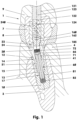
- the Figure 1 shows a prosthetic denture (1) in the form of a complete denture.
- the latter is constructed on several implant bodies (10) screwed into the jawbone (3).
- the jawbone section shown is located - viewed from the patient - in the area of the molars on the right side of the jaw. The cut is oriented perpendicular to the occlusal plane.
- a conical seat (14) contains an angled superstructure main support (20), see also Figure 9
- the superstructure main support (20) is held in the conical seat (14) by means of a special screw bolt (60).
- a top support (240) sits on the individual superstructure main support (20) and is screwed to it by means of a top support screw (160).
- the top support (240) is part of a dimensionally stable metal or plastic reinforcement (7).
- the crowns (9), made of ceramic, for example, are anchored in the reinforcement (7).
- the reinforcement (7) is surrounded by an elastic plastic that replicates the artificial gum (8) surrounding the crowns (9).
- the complete denture is removed from the superstructure main support (20) in a biannual cycle, for example.
- the attachment support screws (160) are accessible with little effort.
- the crowns (9) arranged above the implant bodies (10) in the denture (1) are each provided with a bore (121), to which Figure 1 e.g., a bore (122) connects to the reinforcement (7).
- the bore (121) and part of the bore (122) are sealed with a plug (123) made of a plastic cured under UV light.
- a Teflon tape (124) is caulked as filler material between the plug (123) and the top support screw (160) in the central bore (244) of the top support (240).
- the Teflon tape (124) can be pulled out so that the attachment support screw (160) can then be loosened.
- the Figure 2 shows as prosthetic dentures e.g. a bridge (2), which consists of two to four incisors
- the longitudinal section of the lower jaw runs through one of the front incisors, which is supported in the jawbone (3) by the implant body (10).
- the crown (9) is mounted directly on the short attachment support (240).
- the holes (121, 122) are sealed as previously described.
- the basis of the prosthetic denture (1) is an implant body (10) that can be screwed into the jawbone. It is a hollow screw with a possibly self-tapping, e.g., non-metric external thread.
- the implant body (10) Approximately in the upper half, the implant body (10) has a multi-level recess (13), which is divided into three zones (see figure).
- Figures 1 , 2 and 3 The first zone (14) – located in the area of the implant shoulder (12) of the implant body (10) – is an inner cone with a cone angle of, for example, 18 degrees.
- the inner cone (14) transitions into a hexagon socket (15) in the second zone, which serves as an anti-twist device (44).
- a double hexagon socket or another positive or non-positive anti-twist device can be used as the coupling geometry.
- the first and second zones (14, 15) form the first assembly joint (41).
- the third zone (17) is a threaded hole with an internal clamping thread (82), which, during assembly, accommodates the screw bolt (60) holding the superstructure main beam (20).
- the right-hand internal clamping thread (82) is, for example, an M 1.6 ⁇ 0.35 thread according to DIN 13, Sheet 1.
- the area facing the implant body (10) is the implant neck (42) with its outer cone (43) and its external hexagon (44).
- the outer cone (43) and the external hexagon (44) fit precisely in the recess (13) of the implant body (10).
- the end faces of the external hexagon (44) do not contact the recess (13).
- the implant plate (31) has, at least in part or in part, the shape of a plane or the shape of a truncated cone, the cone angle of which opens towards the tooth crown (9).
- the underside of the implant plate (31) also consists of several conical cones extending from one another, each of which encloses a different angle with respect to the center line (29).
- the outer edge (33) of the implant plate (31) is at a distance from the center line (29) which, for a 360° rotation around the center line (29), is, for example, 4.5 mm.
- the implant post (23) is designed according to the Figures 1 and 2 a conical post (24) which has an anti-twist device (238) in the form of an external hexagon
- the surfaces of the external hexagon are either oriented parallel to the centerline (59) or they are partial surfaces of a straight pyramid with six edges.
- the conical post (24) and the anti-twist device (238) form a centering second assembly joint (239).
- the superstructure main support (20) is coated with a titanium nitride coating, at least above the implant plate (31).
- the coating thickness is, for example, 1 to 4 ⁇ m.
- thin-walled ceramic or copolymer coatings can also be applied there.
- the superstructure main support (20) has a continuous recess (51) which has a kink in the upper area with a kink angle of, for example, 11 degrees.
- the finished recess (51) consists of four zones.
- the first (52) and the second zone (53) are used to insert the screw bolt (60).
- the first, lower zone (52) is a cylindrical bore. Its center line (49) coincides with the center line (29).
- Adjoining it as the second zone (53) is, for example, a right-hand internal thread (72), which is designated M 1.8 ⁇ 0.2 according to DIN 13, Sheet 2.
- the transition between the internal thread (72) and the bore (52) is formed by a flat stop collar (54).
- the fourth, upper zone (57) is also a cylindrical bore with an internal thread (27). Its centerline (59) intersects the centerline (29) in the third zone (56), e.g., at an angle of 11 degrees.
- the upper zone (57) serves, on the one hand, to insert the tool with which the screw bolt (60) is tightened. On the other hand, it is also the seat of the attachment support screw (160).
- the third zone (56) represents a rounded transition area, which, for example, has areas of the outer surface of a hemisphere.
- the system according to the Figures 3 and 4 uses a superstructure main support (21b) which terminates in a spherical post (25) on the attachment support side.
- the implant cone (43) transitions tangentially – without any jump, edge, or implant plate – into the spherical shape of the spherical post (25).
- the center line (59) forms an angle of 158 degrees with the center line (29) at the intersection point (36).
- the bend angle or angulation of the center line (59) relative to the center line (29) is 11 degrees.
- the intersection point (36) is also the center point of the spherical shape of the spherical post (25). This applies to both the outer wall and the wall of its central recess.
- the Figure 10 shows a straight superstructure main beam (21a) in which the centerline of the ball post (25) coincides with the centerline of the structural main beam (21a).
- the ball post (25) ends, according to the Figure 3 , towards the top support (243) in a conical seat (28) into which four notches are machined.
- the notches have four flanks, the surface normals of which are oriented parallel to the center line (59) and lie in one plane. These four flanks form plate segments (32) of an implant plate integrated into the envelope geometry of the conical seat (28). They are, in sum, comparable to the upper edge surface (37) of the superstructure main beam (20). The four other flanks of the notches lie in planes parallel to the center line (59) and represent part of the side surfaces of an imaginary cube. These flanks, which are equidistant from the center line (59), form the anti-rotation device (238).
- the superstructure main beam (21c) shown has a 30° bend, while the superstructure main beam (21d) of the Figure 12 a 45° angle.
- the superstructure main beam (21d) of the Figure 12 a 45° angle.
- the angle of the individual superstructure main beams can also be implemented in three- or five-degree increments.
- the individual screw bolt (60, 61) is generally divided into four sections. These are arranged from front to back: a pivot section (63), a drive section (70), an intermediate section (75), and a clamping section (80), see Fig. Figures 5 and 7 .
- a tool recess (65) is machined into the articulation area (63). It is designed according to the Figures 5 and 7 for example, a hexalobular (66) socket with a wrench size of, for example, 1.28 mm.
- a hexagon socket instead of the hexalobular socket, a hexagon socket, an internal multi-tooth socket, a Phillips recess, a slot, or the like can also be provided.
- Another drive variant is an external hexalobular or external hexagon.
- the hexalobular or hexagonal shapes may be barrel-rounded in the axial direction.
- the drive area (70) has the Figures 5 and 7 a fine thread of type M 1.8 ⁇ 0.2.
- Other fine threads than Drive threads (71, 72) such as M 2 ⁇ 0.25, M 1.8 ⁇ 0.2, M 1.6 ⁇ 0.25 or M 1.6 ⁇ 0.2 are also conceivable.
- the intermediate area (75) adjoining the drive area (70) serves as a spacer to the subsequent clamping area (80).
- the intermediate area (75), after Figure 5 consists of a cylindrical pin (76) and a stop flange (78). If necessary, the outer diameter of the cylindrical pin (76) corresponds to the core diameter of the external drive thread (71).
- a disc-shaped stop flange (78) adjoins the cylindrical pin (76) toward the clamping area (80).
- the stop flange (78) has a wall thickness of, for example, 0.2 mm and an outer diameter of, for example, 1.8 mm.
- the stop flange (78) has a notch (79) parallel to the screw centerline, which allows for venting of the threaded bore of the implant body (10).
- the clamping area (80) represents an external clamping thread (81). In this case, for example, it is a 1.46 mm long M 1.6 ⁇ 0.35 standard thread according to DIN 13, Sheet 1.
- Figure 1 shows the superstructure main beam (20) after inserting the screw bolt (60).
- the screw bolt (60) is screwed with its external drive thread (71) into the area of the internal drive thread (72) until the stop flange (78) of the screw bolt (60) rests against the stop collar (54), see.
- Figures 1 , 2 and 3 The screw bolt (60) is now securely seated in the superstructure main beam (20) in its rear position.
- the combination of the superstructure main beam (20) and the screw bolt (60) can be marketed.
- the external clamping thread (81) is screwed into the internal clamping thread (82) of the implant body (10) by turning the screw bolt (60) clockwise. This draws the superstructure main support (20) into the implant body (10).
- the screwing-in process is complete as soon as the implant cone (43) is firmly seated in the internal cone (14) of the implant body (10). All four threads of the external clamping thread (81) are seated in the internal clamping thread (82). Likewise, the majority of the threads of the external drive thread (71) are seated in the internal drive thread (72).
- the screw bolt (61) of the Figure 7 serves to fix the superstructure main support (21a, 21b, 21c, 21d) in the implant body (10), cf. Figures 3 and 4 It is largely comparable to the screw bolt (60). Essentially, the intermediate section (75) is shorter.
- Each of these support beams (221-223) has a base section (225), a support beam plate (228) for supporting a superstructure (1, 2), and a support beam post (233).
- All attachment beams (221-223) in this group are suitable for mounting on the superstructure main beams (21a-21d).
- a bolt (161) with opposing threads is located between the respective superstructure main beam and the attachment beam mounted on it.
- the attachment bolt (161) is in Figure 8 It is constructed similarly to the screw bolts (60) and (61).
- a stop flange (178) Between a drive section (170) and a clamping section (180) is a stop flange (178), whose diameter is larger than the maximum thread diameter of the clamping section (180).
- the external drive thread (171) corresponds to an M 1.6 ⁇ 0.2 thread according to DIN 13.
- the larger diameter external clamping thread (181) is an M 1.8 standard thread.
- the tool recess machined into the drive section (170) is, for example, a hexalobular socket.
- All threads shown in the examples are metric threads according to DIN 13. Instead of metric threads, trapezoidal threads, flat threads, buttress threads, round or milk threads, pipe threads, Whitworth threads, UNF/UNC threads, or similar threads can also be used. All screw bolts (60, 61) are made of TiAL6V4 or TiAl6V4 ELI, for example.
- each attachment beam widens from the lower end face toward the attachment beam plate (228).
- the attachment beam post (233) located above the attachment beam plate essentially has the shape of a straight cone that tapers upwards—i.e., away from the attachment beam plate (228).
- the attachment beam post (233) has several circumferential grooves in its lower third, which are interrupted by a laterally projecting anti-rotation bar (234). This creates a torsion-proof base for the superstructure (1, 2) to be supported.
- All attachment supports (221-123) have a continuous, multi-stepped recess (251), which has a conical seat (226) in the lower area, see. Figure 16 .
- the conical seat (226) opens into a short cylindrical recess for receiving the Clamping range (180) of the attachment screw bolt (161), see Figure 3.
- the cylindrical recess is followed by the internal drive thread (172), into which the external drive thread (171) of the attachment screw bolt (161) engages.
- the diameter of the cylindrical recess is larger than the core diameter of the internal drive thread (172) of the attachment screw bolt (161). This creates a stop collar against which the stop flange (178) of the attachment screw bolt (161) rests during pre-assembly.
- the base section (225) of the top support (222) is angled by 11 degrees relative to the top support post (233). For the top support (223), this angle is 22 degrees.
- the Figures 17 to 20 show the attachment supports (241-243). All of these attachment supports consist of a straight or cylindrical tube, which is smooth-walled in the lower section and equipped with circumferential grooves (246) in the upper section, for example.
- the tube has an outer diameter of 3.24 mm, for example.
- the grooves have a radius of 0.45 mm.
- the pitch from groove to groove is 1.1 mm.
- the smallest inner diameter of the tube is 1.62 mm.
- the smooth-walled area of the attachment support (242) is angled by eleven degrees compared to the grooved area.
- Figure 19 The angle is 22 degrees.
- the geometric shape of the second assembly joint of the add-on supports (241-243) corresponds to the geometric shape of the add-on supports (221-223).
- the scanning gauge (270) shown here has a scanning tooth (271) projecting radially on one side at its free end.
- the scannable, 2.5 mm thick scanning tooth (270) has two parallel faces and two tooth flanks enclosing a 40° angle.
- any combination of straight or angled superstructure main supports (20; 21a-21d) and straight or angled attachment supports (221-223; 240-243) a multitude of angular positions between the implant body and the position of the attachment supports can be created, taking into account the fact that the supports can also be positioned rotated relative to each other.
- the number of angular positions also increases if, in one case or another, the anti-rotation device between the individual superstructure main support (20; 21a-21d) and the individual attachment support (221-223; 240-243) is omitted.
Landscapes
- Health & Medical Sciences (AREA)
- Animal Behavior & Ethology (AREA)
- Dentistry (AREA)
- Epidemiology (AREA)
- Life Sciences & Earth Sciences (AREA)
- Oral & Maxillofacial Surgery (AREA)
- General Health & Medical Sciences (AREA)
- Public Health (AREA)
- Veterinary Medicine (AREA)
- Orthopedic Medicine & Surgery (AREA)
- Dental Prosthetics (AREA)
- Physics & Mathematics (AREA)
- Optics & Photonics (AREA)
- Prostheses (AREA)
Description
- Die Erfindung betrifft eine Systemmontageschnittstelle mit einem eine Suprakonstruktion tragenden mehrteiligen Suprastrukturträger und einem ein Spanninnengewinde aufweisenden Implantatkörper, wobei ein Teil des Suprastrukturträgers über einen Implantatschraubbolzen am Implantatkörper angeordnet ist.
- In der zahnärztlichen Implantologie wird u.a. im Rahmen der Herstellung eines prothetischen Einzelzahnersatzes häufig ein enossaler Implantatkörper verwendet, der die Prothese trägt. In diesem Fall wird der Implantatkörper, eine Art Schraubdübel, in eine künstlich im Patientenkiefer erzeugte Bohrung eingeschraubt. Der eingeschraubte Implantatkörper nimmt bei der fertigen Prothese einen Implantatpfosten auf. Letzterer wird verdrehsicher im Implantatkörper mit einem speziellen Spannmittel befestigt. Auf den Implantatpfosten wird direkt oder indirekt eine, die sichtbare Zahnkrone bildende Suprastruktur, z.B. durch Verkleben, aufgesetzt. Wird anstelle der Zahnkrone eine Brücke, eine Teil- oder Vollprothese benötigt, werden letztere durch mehrere Kombinationen aus Implantatkörpern und Suprastruktuträgern gebildet.
- Aus der
WO 2012/039 819 A1 ist ein Zahnimplantataufbausystem bekannt, bei dem ein Suprastrukturträger ohne Implantatpfosten mittels einer Abutmentschraube an einem Implantatkörper befestigt ist. Um einen prothesentragenden Implantantpfosten am Suprastrukturkörper mittels Schraubverbindung befestigen zu können, ist am Supratrukturtäger ein gegen die Mittelline des Implantatkörpers geneigter Implantatteller mit zentralem Innengewinde ausgebildet. Damit weist der Suprastrukturkörper zwei verschiedene Bohrungen auf, die in drei Öffnungen des Suprastrukturträgers enden. - Aus der
DE 203 03 653 U1 ist eine Verbindunganordnung mit einem Basisteil und mit einem Abutment bekannt. Diese beiden Teile sind mittels einer Basisschraube miteinander gefügt. Am Abutment kann eine Krone oder ein anderes Prothetikteil befestigt werden. - Die
US 2017/0231726 offenbart ein Abutmentsystem, wobei ein abgewinkeltes Abutment mittels eines Gewindebolzens im Implantatkörper befestigt ist. Der Gewindebolzen hat zwei einander gegenläufige Gewinde, wahlweise mit unterschiedlicher Gewindesteigung. - Aus der
DE 101 01 907 A1 ist ein System aus einem Implantat, einem Aufbaupfosten und einem Suprastrukturträger bekannt, die mittels zweier identischer Schraubbolzen mit gegenläufigen Gewinden miteinander verbunden sind. - Der vorliegenden Erfindung liegt die Problemstellung zugrunde, eine Systemmontageschnittstelle zwischen einem Suprastrukturträger und einem Implantatkörper so zu verbessern, dass zum einen bei einfacher Vor- und Endmontage ein sicheres Tragen der Suprakonstruktion gewährleistet ist und dass zum anderen bei mehreren eine Teil- oder Totalprothese tragenden Implantatkörpern trotz statischer Überbestimmtheit keine messbaren Verspannungen auftreten.
- Diese Problemstellung wird mit den Merkmalen des Patentanspruchs 1 gelöst. Dabei besteht der Suprastrukturträger aus einem Suprastrukturhauptträger und aus einem mit ihm lösbar verschraubten Aufsatzträger. Der Suprastrukturhauptträger hat eine zum Aufsatzträger und zum Implantatkörper hin offene Ausnehmung. In der Ausnehmung ist in ihrem dem Implantatkörper zugewandten Bereich ein Antriebsinnengewinde angeordnet. Der Implantatschraubbolzen weist zwei mit oder ohne Abstand hintereinander angeordnete Außengewinde auf, von denen das erste ein Antriebsaußengewinde und das zweite ein Spannaußengewinde ist. Beide Außengewinde weisen unterschiedliche Steigungen bei gleichem oder unterschiedlichem Steigungsvorzeichen auf. Das Antriebsaußengewinde passt in das Antriebsinnengewinde der Ausnehmung des Suprastrukturhauptträgers und das Spannaußengewinde passt in das Spanninnengewinde des Implantatkörpers. Der Aufsatzträger hat eine zur Suprakonstruktion und zum Suprastrukturhauptträger hin offene Ausnehmung. In der Ausnehmung ist in ihrem dem Suprastrukturhauptträger zugewandten Bereich ein Antriebsinnengewinde angeordnet. Zwischen dem jeweiligen Suprastrukturhauptträger und dem darauf aufgesetzten Aufsatzträger befindet sich ein Aufsatzschraubbolzen mit gegenläufigen Antriebsaußengewinde und Spannaußengewinde. Außerdem greift das Antriebsaußengewinde des Aufsatzschraubbolzens in das Antriebsinnengewinde des Aufsatzträgers ein.
- Mit der Erfindung wird eine Systemmontageschnittstelle geschaffen, die einen Implantatkörper über einen Suprastrukturhauptträger und einen Aufsatzträger mit einer Suprakonstruktion verbindet. Dabei können die Suprastrukturhauptträger und die Aufsatzträger zwischen dem Implantatkörper und der Suprakonstruktion zum einen gegenseitig in den Montagefugen verschwenkt werden. Zum anderen gibt es eine Vielzahl von Suprastrukturhauptträgern und Aufsatzträgern, die sich untereinander nur dadurch unterscheiden, dass sie verschiedene Abwinkelungen aufweisen. Auf diese Weise bilden der Implantatkörper, der Suprastrukturhauptträger und der Aufsatzträger einen über Schraubbolzen und/oder Schrauben aneinandergereihten - in der Regel nicht geradlinig verlaufenden - Träger mit zwei Montagefugen. Alle drei im Wesentlichen rohrförmigen Bauteile sind bis auf eine endseitige Öffnung, in deren Innengewinde die Suprakonstruktion mittels Schraubbolzen oder Schraube gehalten wird, ringsherum geschlossen, sodass entlang dem neu geschaffenen Träger nahezu keine die Bauteilfestigkeit negativ beeinträchtigenden Kerbwirkungen entstehen.
- Selbstverständlich kann in der ersten Montagefuge der Schraubbolzen gegen eine mit einem Schraubenkopf versehene Schraube ausgetauscht werden.
- Weitere Einzelheiten der Erfindung ergeben sich aus den Unteransprüchen und der nachfolgenden Beschreibung schematisch dargestellter Ausführungsformen.
- Figur 1:
- Längsschnitt durch eine Systemmontageschnittstelle einer implantatgetragenen Totalprothese;
- Figur 2:
- Längsschnitt durch einen prothetischen Zahnersatz in Form einer Teilprothese;
- Figur 3:
- Längsschnitt durch eine Systemmontageschnittstelle mit mehrfacher Abknickung;
- Figur 4:
- perspektivische Ansicht zu
Figur 3 ; - Figur 5:
- perspektivische Ansicht eines langen Implantatschraubbolzens;
- Figur 6:
- perspektivische Ansicht einer Aufsatzträgerschraube;
- Figur 7:
- perspektivische Ansicht eines kurzen Implantatschraubbolzens;
- Figur 8:
- perspektivische Ansicht eines Aufsatzträgerschraubbolzens;
- Figur 9:
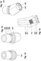
- perspektivische Ansicht eines Suprastrukturhauptträgers mit Konuspfosten;
- Figur 10:
- perspektivische Ansicht eines geraden Suprastrukturhauptträgers mit Kugelpfosten;
- Figur 11:
- wie
Figur 10 , jedoch mit abgewinkelter Ausnehmung zur Aufnahme eines Aufsatzträgerbefestigungsmittels; - Figur 12:
- wie
Figur 11 , jedoch mit größerer Abwinkelung; - Figur 13:
- perspektivische Ansicht eines geraden Aufsatzträgers mit Abstützteller;
- Figur 14:
- wie
Figur 13 , jedoch mit abgewinkeltem Aufsatzträgerpfosten; - Figur 15:
- wie
Figur 14 , jedoch mit stärker abgewinkeltem Aufsatzträgerpfosten; - Figur 16:
- Längsschnitt zu
Figur 15 ; - Figur 17:
- perspektivische Ansicht eines geraden Aufsatzträgers ohne Abstützteller;
- Figur 18:
- wie
Figur 17 , jedoch als abgewinkelter Aufsatzträger; - Figur 19:
- wie
Figur 18 , jedoch mit stärkerer Abwinkelung; - Figur 20:
- perspektivische Ansicht eines geraden Abtaststifts mit Verdrehsicherung;
- Die
Figur 1 zeigt einen prothetischen Zahnersatz (1) in Form einer Totalprothese. Letztere ist auf mehreren im Kieferknochen (3) eingeschraubten Implantatkörpern (10) aufgebaut. Der gezeigte Kieferknochenschnitt liegt - vom Patient aus betrachtet - im Bereich der Backenzähne der rechten Kieferseite. Der Schnitt ist z.B. senkrecht zur Kauebene orientiert. Im Implantatkörper (10) sitzt in einem Konussitz (14) ein z.B. abgewinkelter Suprastrukturhauptträger (20), vgl. auchFigur 9 . Der Suprastrukturhauptträger (20) wird mit Hilfe eines speziellen Schraubbolzens (60) im Konussitz (14) gehalten. Auf dem einzelnen Suprastrukturhauptträger (20) sitzt - mittels einer Aufsatzträgerschraube (160) verschraubt - ein Aufsatzträger (240). Der Aufsatzträger (240) ist Teil einer formsteifen Metall- oder Kunststoffarmierung (7). In der Armierung (7) sind die z.B. aus einer Keramik gefertigten Kronen (9) verankert. Zwischen dem Zahnfleisch (4) und der Krone (9) umgibt die Armierung (7) ein elastischer Kunststoff als Nachbildung des die Kronen (9) umgebenden künstlichen Zahnfleisches (8). - Zur Reinigung und zu Wartungszwecken wird die Totalprothese in einem z.B. halbjährlichen Zyklus von den Suprastrukturhauptträger (20) gelöst. Um das zu ermöglichen, sind die Aufsatzträgerschrauben (160) mit geringem Aufwand zugänglich. Dazu sind im Zahnersatz (1) die über den Implantatkörpern (10) angeordneten Kronen (9) jeweils mit einer Bohrung (121) versehen, an die sich nach
Figur 1 z.B. in der Armierung (7) eine Bohrung (122) anschließt. Die Bohrung (121) und ein Teil der Bohrung (122) sind mit einem Verschlusspfropfen (123) aus einem unter UV-Licht ausgehärteten Kunststoff verschlossen. Zwischen dem Verschlusspfropfen (123) und der Aufsatzträgerschraube (160) ist in der zentralen Bohrung (244) des Aufsatzträgers (240) als Füllmaterial ein Teflonband (124) verstemmt. - Nach einem problemlosen Aufbohren des Verschlusspfropfens (123) kann das Teflonband (124) herausgezogen werden, um danach die Aufsatzträgerschraube (160) lösen zu können.
- Die
Figur 2 zeigt als prothetischen Zahnersatz z.B. eine Brücke (2), die beispielsweise aus zwei bis vier Schneidezähnen besteht. Der Unterkieferlängsschnitt verläuft durch einen der vorderen Schneidezähne, der mittels des Implantatkörpers (10) im Kieferknochen (3) abgestützt ist. Hier ist die Krone (9) direkt auf dem kurzen Aufsatzträger (240) aufgebaut. Das Verschließen der Bohrungen (121, 122) erfolgt wie zuvor schon beschrieben. - Die Basis des prothetischen Zahnersatzes (1) ist ein in den Kieferknochen einschraubbarer Implantatkörper (10). Er ist eine Hohlschraube mit einem ggf. selbstschneidenden, z.B. nichtmetrischen Außengewinde. Circa in der oberen Hälfte weist der Implantatkörper (10) die mehrstufige Ausnehmung (13) auf, die in drei Zonen aufgeteilt ist, vgl.
Figuren 1 ,2 und3 . Die erste Zone (14) - sie liegt im Bereich der Implantatschulter (12) des Implantatkörpers (10) - ist ein Innenkonus, der einen Kegelwinkel von z.B. 18 Winkelgraden aufweist. Der Innenkonus (14) geht in einen als Verdrehsicherung (44) dienenden Innensechskant (15) der zweiten Zone über. Anstelle des Innensechskants (15) kann als Kupplungsgeometrie z.B. auch ein Doppelinnensechskant oder eine andere form- oder kraftschlüssige Verdrehsicherungsgeometrie verwendet werden. Die erste und die zweite Zone (14, 15) bilden die erste Montagefuge (41). - Die dritte Zone (17) ist eine Gewindebohrung mit einem Spanninnengewinde (82), das bei der Montage den den Suprastrukturhauptträger (20) haltenden Schraubbolzen (60) aufnimmt. Das rechtssteigende Spanninnengewinde (82) ist beispielsweise ein M 1,6 × 0,35-Gewinde nach DIN 13, Blatt 1.
- Der Suprastrukturhauptträger (20) hat primär die Aufgabe - im Implantatkörper (10) sitzend - als erste Basis für die künstliche Zahnkrone (1, 2) zu dienen. Er hat einen Bereich, der dem Implantatkörper (10) und einen Bereich, der dem Aufsatzträger (240) zugewandt ist.
- Der dem Implantatkörper (10) zugewandte Bereich ist der Implantathals (42) mit seinem Außenkonus (43) und seinem Außensechskant (44). Der Außenkonus (43) und der Außensechskant (44) sitzen passgenau in der Ausnehmung (13) des Implantatkörpers (10). In der zur Spitze des Implantatkörpers (10) weisenden axialen Richtung kontaktieren die Stirnflächen des Außensechskants (44) die Ausnehmung (13) nicht.
- Oberhalb des Implantathalses (42) schließt sich ein Implantatteller (31) an, der ggf. mit einem stetigen Übergang aus dem Implantathals (42) hervorgeht. Der Implantatteller (31) hat zumindest bereichs- oder abschnittsweise die Form einer Ebene oder die Form eines Kegelstumpfmantels, dessen Konuswinkel sich zur Zahnkrone (9) hin öffnet. Beispielsweise besteht die Unterseite des Implantattellers (31) auch aus mehreren auseinander hervorgehenden Kegelkoni, wobei jeder gegenüber der Mittellinie (29) einen anderen Winkel einschließt. Der äußere Rand (33) des Implantattellers (31) hat hier einen Abstand zur Mittellinie (29), der bei einer 360°-Rotation um die Mittellinie (29) z.B. 4,5 mm beträgt.
- Oberhalb des Implantattellers (31), der eine flächige Randoberseite (37) hat, erhebt sich ein konusförmiger Implantatpfosten (23). Die flächige Randoberseite (37) bildet ggf. eine Aufsitzfläche für den Aufsatzträger (240). Der Implantatpfosten (23) ist gemäß den
Figuren 1 und2 ein Kegelpfosten (24), der eine Verdrehsicherung (238) in Form eines Außensechskants aufweist. Die Flächen des Außensechskants sind entweder parallel zur Mittellinie (59) orientiert oder sie sind Teilflächen einer mit sechs Kanten ausgestatteten geraden Pyramide. Der Kegelpfosten (24) und die Verdrehsicherung (238) bilden eine zentrierende zweite Montagefuge (239). - Ggf. ist der Suprastrukturhauptträger (20) zumindest oberhalb des Implantattellers (31) mit einer Titannitridbeschichtung ausgestattet. Ihre Schichtdicke beträgt z.B. 1 bis 4 µm. Alternativ können dort auch dünnwandige Keramik- oder Copolymerbeschichtungen aufgetragen sein.
- Nach den
Figuren 1 und2 hat der Suprastrukturhauptträger (20) eine durchgehende Ausnehmung (51), die im oberen Bereich eine Knickstelle mit einem Knickwinkel von z.B. 11 Winkelgraden aufweist. Die fertig bearbeitete Ausnehmung (51) besteht aus vier Zonen. Die erste (52) und die zweite Zone (53) dienen dem Einführen des Schraubbolzens (60). Die erste, untere Zone (52) ist eine zylindrische Bohrung. Ihre Mittellinie (49) deckt sich mit der Mittellinie (29). An sie schließt sich als zweite Zone (53) z.B. ein rechtsgängiges Innengewinde (72) an, das nach DIN 13, Blatt 2 mit M 1,8 × 0,2 bezeichnet wird. Den Übergang zwischen dem Innengewinde (72) und der Bohrung (52) bildet ein planer Anschlagbund (54). - Die vierte, obere Zone (57) ist ebenfalls eine zylindrische Bohrung mit einem Innengewinde (27). Ihre Mittellinie (59) schneidet die Mittellinie (29) in der dritten Zone (56), z.B. unter einem Winkel von 11 Winkelgraden. Die obere Zone (57) dient zum einen der Einführung des Werkzeuges, mit dem der Schraubbolzen (60) angezogen wird. Zum anderen ist sie auch Sitz der Aufsatzträgerschraube (160). Die dritte Zone (56) stellt einen ausgerundeten Übergangsbereich dar, der z.B. Bereiche der Mantelfläche einer Halbkugel aufweist.
- Das System nach den
Figuren 3 und 4 verwendet einen Suprastrukturhauptträger (21b) der aufsatzträgerseitig in einem Kugelpfosten (25) endet. Der Implantatkonus (43) geht tangential - ohne Sprung, Kante oder Implantatteller - in die Kugelform des Kugelpfostens (25) über. Die Mittellinie (59) schließt mit der Mittellinie (29) im Schnittpunkt (36) einen Winkel von 158 Winkelgraden ein. Somit beträgt der Knickwinkel bzw. die Abwinkelung der Mittellinie (59) gegenüber der Mittellinie (29) 11 Winkelgrade. Der Schnittpunkt (36) ist zugleich der Mittelpunkt der Kugelform des Kugelpfostens (25). Dies betrifft sowohl die Außenwandung als auch die Wandung seiner zentralen Ausnehmung. - In den
Figuren 10-12 sind drei weitere Suprastrukturhauptträger (21a, 21c, 21d) dieser Serie dargestellt. - Die
Figur 10 zeigt einen geraden Suprastrukturhauptträger (21a), bei dem die Mittellinie des Kugelpfostens (25) mit der Mittellinie des Strukturhauptträgers (21a) übereinstimmt. Der Kugelpfosten (25) endet, gemäß derFigur 3 , zum Aufsatzträger (243) hin in einem Konussitz (28), in den vier Kerben eingearbeitet sind. Die Mantellinien des Mantels des Konussitzes (28), die sich in einem Punkt der Mittellinie (59) schneiden, liegen tangential an der Kugeloberfläche des Kugelpfostens (25) an. - Die Kerben weisen vier Flanken auf, deren Flächennormalen zum einen parallel zur Mittellinie (59) orientiert sind und zum anderen in einer Ebene liegen. Diese vier Flanken bilden als Tellersegmente (32) einen in die Hüllgeometrie des Konussitzes (28) integrierten Implantatteller. Sie sind in der Summe vergleichbar mit der Randoberseite (37) des Suprastrukturhauptträgers (20). Die vier anderen Flanken der Kerben liegen in Ebenen, die parallel zur Mittellinie (59) ausgerichtet sind und Teil der Seitenflächen eines gedachten Würfels darstellen. Diese Flanken, die von der Mittellinie (59) gleich weit entfernt sind, bilden die Verdrehsicherung (238).
- Der in
Figur 11 abgebildete Suprastrukturhauptträger (21c) weist eine 30°-Abwinkelung auf, während der Suprastrukturhauptträger (21d) derFigur 12 eine 45°-Abwinkelung zeigt. Selbstverständlich gibt es auch einen Suprastrukturhauptträger dieser Serie mit einer 11°-Abwinkelung. Die Abwinkelung der einzelnen Suprastrukturhauptträger kann auch in Drei- oder Fünfwinkelgradschritten ausgeführt werden. - Der einzelne Schraubbolzen (60, 61) ist in der Regel in vier Bereiche aufgeteilt. Diese sind von vorn nach hinten aneinandergereiht ein Anlenkbereich (63), ein Antriebsbereich (70), ein Zwischenbereich (75) und ein Spannbereich (80), vgl.
Figu-ren 5 und 7 . - In den Anlenkbereich (63) ist eine Werkzeugausnehmung (65) eingearbeitet. Sie ist nach den
Figuren 5 und 7 z.B. ein Innensechsrund (66) mit einer Schlüsselweite von z.B. 1,28 mm. Anstelle des Innensechsrunds kann auch ein Innensechskant, ein Innenvielzahn, ein Kreuzschlitz, ein Schlitz oder dergleichen vorgesehen sein. Eine andere Antriebsvariante stellt ein Außensechsrund oder Außensechskant dar. Ggf. sind die Sechsrund- oder Sechskantformen in Axialrichtung tonnenförmig abgerundet. - Der Antriebsbereich (70) weist nach den
Figuren 5 und 7 ein Feingewinde des Typs M 1,8 × 0,2 auf. Andere Feingewinde als Antriebsgewinde (71, 72) wie z.B. M 2 × 0,25, M 1,8 × 0,2, M 1,6 × 0,25 oder M 1,6 × 0,2 sind ebenfalls denkbar. - Der an den Antriebsbereich (70) anschließende Zwischenbereich (75) dient als Abstandshalter zum nachfolgenden Spannbereich (80). Der Zwischenbereich (75), nach
Figur 5 , setzt sich aus einem Zylinderzapfen (76) und einem Anschlagflansch (78) zusammen. Ggf. entspricht der Außendurchmesser des Zylinderzapfens (76) dem Kerndurchmesser des Antriebsaußengewindes (71). - Zum Spannbereich (80) hin schließt sich an den Zylinderzapfen (76) ein scheibenförmiger Anschlagflansch (78) an. Der Anschlagflansch (78) hat eine Wandstärke von z.B. 0,2 mm bei einem Außendurchmesser von z.B. 1,8 mm. Der Anschlagflansch (78) weist parallel zur Schraubenmittellinie eine Kerbe (79) auf, die die Entlüftung der Gewindebohrung des Implantatkörpers (10) ermöglicht.
- Der Spannbereich (80) stellt ein Spannaußengewinde (81) dar. Es ist hier z.B. ein 1,46 mm langes M 1,6 × 0,35-Regelgewinde nach DIN 13, Blatt 1.
-
Figur 1 zeigt den Suprastrukturhauptträger (20) nach dem Einsetzen des Schraubbolzens (60). Für die Montage wird der Schraubbolzen (60) mit seinem Antriebsaußengewinde (71) in den Bereich des Antriebsinnengewindes (72) eingeschraubt, bis der Anschlagflansch (78) des Schraubbolzens (60) am Anschlagbund (54) anliegt, vgl.Figuren 1 ,2 und3 . Nun sitzt der Schraubbolzen (60) verliersicher im Suprastrukturhauptträger (20) in seiner hinteren Position. In dieser Form kann die Kombination aus dem Suprastrukturhauptträger (20) und dem Schraubbolzen (60) in den Handel gelangen. - Nach dem Einsetzen des Suprastrukturhauptträgers (20) in die gestufte Ausnehmung (13) wird das Spannaußengewinde (81) in das Spanninnengewinde (82) des Implantatkörpers (10) durch eine Rechtsdrehung des Sschraubbolzens (60) eingeschraubt. Hierdurch wird der Suprastrukturhauptträger (20) in den Implantatkörper (10) hineingezogen. Der Einschraubvorgang ist beendet, sobald der Implantatkonus (43) fest im Innenkonus (14) des Implantatkörpers (10) sitzt. Alle vier Gewindegänge des Spannaußengewindes (81) sitzen im Spanninnengewinde (82). Ebenso liegen die Mehrzahl der Gewindegänge des Antriebsaußengewindes (71) im Antriebsinnengewinde (72).
- Der Schraubbolzen (61) der
Figur 7 dient der Befestigung des Suprastrukturhauptträgers (21a, 21b, 21c, 21d) im Implantatkörper (10), vgl.Figuren 3 und 4 . Er ist mit dem Schraubbolzen (60) weitgehend vergleichbar. Im Wesentlichen ist der Zwischenbereich (75) kürzer ausgebildet. - In den
Figuren 13-16 ist eine aus drei Aufsatzträgern (221-223) bestehende Aufsatzträgergruppe dargestellt. Jeder dieser Aufsatzträger (221-223) weist einen Basisabschnitt (225), einen Aufsatzträgerteller (228) zur Abstützung einer Suprakonstruktion (1, 2) und einen Aufsatzträgerpfosten (233) auf. - Alle Aufsatzträger (221-223) dieser Gruppe sind geeignet, auf den Suprastrukturhauptträgern (21a-21d) angeordnet zu werden. Zwischen dem jeweiligen Suprastrukturhauptträger und dem darauf aufgesetzten Aufsatzträger befindet sich ein Aufsatzschraubbolzen (161) mit gegenläufigen Gewinden.
- Der Aufsatzschraubbolzen (161) ist in
Figur 8 dargestellt. Er ist ähnlich aufgebaut wie die Schraubbolzen (60) und (61). - Zwischen einem Antriebsbereich (170) und einem Spannbereich (180) befindet sich ein Anschlagflansch (178), dessen Durchmesser größer ist als der maximale Gewindedurchmesser des Spannbereichs (180). Das Antriebsaußengewinde (171) entspricht nach DIN 13 einem M 1,6 × 0,2-Gewinde. Das im Durchmesser größere Spannaußengewinde (181) ist ein M 1,8-Regelgewinde. Die in den Antriebsbereich (170) eingearbeitete Werkzeugausnehmung ist beispielsweise ein Innensechsrund.
- Alle in den Ausführungsbeispielen gezeigten Gewinde sind metrische Gewinde nach DIN 13. Anstelle der metrischen Gewinde können auch Trapezgewinde, Flachgewinde, Sägengewinde, Rund- bzw. Milchgewinde, Rohrgewinde, Whitworth-Gewinde, UNF/UNC-Gewinde oder dergleichen verwendet werden. Alle Schraubbolzen (60, 61) sind beispielsweise aus TiAL6V4 oder TiAl6V4 ELI gefertigt.
- Der Basisabschnitt (225) des jeweiligen Aufsatzträgers verbreitert sich von der unteren Stirnfläche hin zum Aufsatzträgerteller (228). Der sich oberhalb des Aufsatzträgertellers befindende Aufsatzträgerpfosten (233) hat im Wesentlichen die Form eines sich nach oben - also weg vom Aufsatzträgerteller (228) - verjüngenden geraden Konus. Der Aufsatzträgerpfosten (233) weist im unteren Drittel mehrere umlaufende Rillen auf, die durch einen seitlich vorstehenden Verdrehsicherungssteg (234) unterbrochen werden. Dadurch entsteht eine verdrehsichere Basis für die zu tragende Suprakonstruktion (1, 2).
- Alle Aufsatzträger (221-123) haben eine durchgehende mehrfach gestufte Ausnehmung (251), die im unteren Bereich eine Konussitz (226) aufweist, vgl.
Figur 16 . Im Konussitz (226) befinden sich z.B. vier Stege (227), die formschlüssig in die Kerben der Verdrehsicherung (32, 238) passen. Der Konussitz (226) mündet in eine kurze zylindrische Ausnehmung zur Aufnahme des Spannbereichs (180) des Aufsatzschraubbolzens (161), vgl. Figur 3. An die zylindrische Ausnehmung schließt sich das Antriebsinnengewinde (172) an, in das das Antriebsaußengewinde (171) des Aufsatzschraubbolzens (161) eingreift. Der Durchmesser der zylindrischen Ausnehmung ist größer als der Kerndurchmesser des Antriebsinnengewindes (172) des Aufsatzschraubbolzens (161). Dadurch entsteht ein Anschlagbund, an dem bei der Vormontage des Aufsatzschraubbolzens (161) dessen Anschlagflansch (178) zur Anlage kommt. - Der Basisabschnitt (225) des Aufsatzträgers (222) ist gegenüber dem Aufsatzträgerpfosten (233) um elf Winkelgrade abgewinkelt. Beim Aufsatzträger (223) beträgt diese Abwinkelung 22 Winkelgrade.
- Die
Figuren 17 bis 20 zeigen die Aufsatzträger (241-243). Alle diese Aufsatzträger bestehen aus einem geraden oder einem zylindrischen Rohr, das im unteren Bereich glattwandig und dem oberen Bereich mit z.B. umlaufenden Rillen (246) ausgestattet ist. Das Rohr hat einen Außendurchmesser von z.B. 3,24 mm. Die Rillen haben im Ausführungsbeispiel einen Radius von 0,45 mm. Die Teilung von Rille zu Rille beträgt 1,1 mm. Der kleinste Innendurchmesser des Rohres beträgt 1,62 mm. - Gemäß
Figur 18 ist der glattwandige Bereich des Aufsatzträgers (242) gegenüber dem mit Rillen ausgestatteten Bereich um elf Winkelgrade abgewinkelt ausgeführt. BeiFigur 19 beträgt die Abwinkelung 22 Winkelgrade. Die Geometrieform der zweiten Montagefuge der Aufsatzträger (241-243) entspricht der Geometrieform der Aufsatzträger (221-223). Vergleichbares gilt für die inFigur 20 dargestellte Abtastlehre (270). Letztere weist an ihrem freien Ende einen einseitig radial abstehenden Abtastzahn (271) auf. Der abscannbare, 2,5 mm dicke Abtastzahn (270) hat zwei parallele Stirnflächen und zwei einen 40°-Winkel einschließende Zahnflanken. - Mithilfe beliebiger Kombinationen aus geraden oder abgewinkelten Suprastrukturhauptträgern (20; 21a-21d) und geraden oder abgewinkelten Aufsatzträgern (221-223; 240-243) können bei Berücksichtigung der Tatsache, dass die Träger auch gegeneinander verdreht positioniert werden können, eine Vielzahl von Winkelstellungen zwischen dem Implantatkörper und der Lage der Aufsatzträger erzeugt werden. Die Zahl der Winkelstellungen vergrößert sich zudem, wenn in dem einen oder anderen Fall die Verdrehsicherung zwischen dem einzelnen Suprastrukturhauptträger (20; 21a-21d) und dem einzelnen Aufsatzträger (221-223; 240-243) weggelassen wird.
-
- 1
- Zahnersatz, prothetisch, Teil- oder Totalprothese, Suprakonstruktion
- 2
- Zahnersatz, prothetisch, Brücke, Suprakonstruktion
- 3
- Kieferknochen
- 4
- Zahnfleisch
- 7
- Gerüst, Armierung
- 8
- Zahnfleischnachbildung, elastisch
- 9
- Krone
- 10
- Implantatkörper
- 12
- Implantatschulter
- 13
- Ausnehmung, gestuft
- 14
- Innenkonus, erste Zone, Konus, Konussitz
- 15
- Innensechskant, zweite Zone, Kupplungsgeometrie
- 17
- Gewindebohrung, dritte Zone für (82)
- 20
- Suprastrukturhauptträger zu Schraubbolzen (60)
- 21a
- Suprastrukturhauptträger zu Schraubbolzen (61), gerade
- 21b
- Suprastrukturhauptträger zu Schraubbolzen (61), 22°-Abwinkelung
- 21c
- Suprastrukturhauptträger zu Schraubbolzen (61), 30°-Abwinkelung
- 21d
- Suprastrukturhauptträger zu Schraubbolzen (61), 45°-Abwinkelung
- 23
- Implantatpfosten
- 24
- Kegelform, Hohlkegel, Kegelpfosten
- 25
- Kugelform, Hohlkugel, Kugelpfosten
- 27
- Innengewinde für (160)
- 28
- Konussitz, Teile einer Kerbe, Verdrehsicherung
- 29
- Mittellinie
- 31
- Implantatteller
- 32
- Tellersegmente, Teil einer Kerbe
- 33
- Rand
- 36
- Mittelpunkt, Schnittpunkt
- 37
- Randoberseite, flächig
- 41
- erste Montagefuge
- 42
- Implantathals
- 43
- Implantatkonus, Außenkonus
- 44
- Verdrehsicherung, Außensechskant, Kupplungsgeometrie
- 51
- Ausnehmung, ggf. geknickt
- 52
- erste, untere Zone, untere Ausnehmung
- 53
- zweite Zone, untere Ausnehmung
- 54
- Anschlagbund
- 56
- dritte Zone, Halbkugelmantelfläche
- 57
- vierte, obere Zone; Bohrung, zylindrisch
- 59
- Mittellinie von (56, 57)
- 60
- Schraubbolzen mit Anschlagflansch, lang
- 61
- Schraubbolzen mit gegenläufigen Gewinden
- 63
- Anlenkbereich
- 65
- Werkzeugausnehmung
- 66
- Innensechsrund, Innensechskant
- 70
- Antriebsbereich
- 71
- Antriebsaußengewinde, Außengewinde, Antriebsgewinde, Linksgewinde
- 72
- Antriebsinnengewinde, Innengewinde, Antriebsgewinde, Linksgewinde
- 73
- Antriebspaarung, Antriebsgewinde, Paarung
- 75
- Zwischenbereich
- 76
- Zylinderzapfen
- 78
- Anschlagflansch, Anschlagbund
- 79
- Kerbe
- 80
- Spannbereich
- 81
- Spannaußengewinde, Außengewinde, Spanngewinde
- 82
- Spanninnengewinde, Innengewinde, Spanngewinde
- 83
- Spannpaarung, Spanngewinde, Paarung
- 121
- Bohrung in (9)
- 122
- Bohrung in (7)
- 123
- Verschlusspfropfen für (9) und/oder (240)
- 124
- Füllmaterial, unverklebt; Teflonband
- 151
- Ausnehmung, ggf. geknickt
- 160
- Aufsatzträgerschraube mit Kopf, kurz
- 161
- Aufsatzschraubbolzen mit gegenläufigen Gewinden; Aufsatzträgerbefestigungsmittel
- 162
- Schraubenkopfsitzfläche, konisch
- 165
- Werkzeugausnehmung
- 166
- Innensechskant
- 167
- Schraubenkopf, radial außen zylindrisch
- 168
- Außengewinde
- 170
- Antriebsbereich
- 171
- Antriebsaußengewinde, Außengewinde, Antriebsgewinde, Linksgewinde
- 172
- Antriebsinnengewinde, Innengewinde, Antriebsgewinde, Linksgewinde
- 173
- Antriebspaarung, Antriebsgewinde, Paarung
- 178
- Anschlagflansch, Anschlagbund
- 180
- Spannbereich
- 181
- Spannaußengewinde, Außengewinde, Spanngewinde
- 182
- Spanninnengewinde, Innengewinde, Spanngewinde
- 183
- Spannpaarung, Spanngewinde, Paarung
- 185
- Außengewinde, Rechtsgewinde
- 221
- Aufsatzträger mit Teller, gerade
- 222
- Aufsatzträger mit 11°-Abwinkelung
- 223
- Aufsatzträger mit 22°-Abwinkelung
- 225
- Basisabschnitt
- 226
- Konussitz
- 227
- Stege
- 228
- Aussatzträgerteller
- 233
- Aufsatzträgerpfosten
- 234
- Verdrehsicherungssteg
- 238
- Verdrehsicherung, Außenvierkant, Kupplungsgeometrie
- 239
- zweite Montagefuge
- 240
- Aufsatzträger, kurz mit Rillen, gerade
- 241
- Aufsatzträger, lang mit Rillen, gerade
- 242
- Aufsatzträger, lang mit 11°-Abwinkelung
- 243
- Aufsatzträger, lang mit 22°-Abwinkelung
- 244
- Bohrung, zentral
- 246
- Rillen
- 251
- Ausnehmung, ggf. geknickt
- 270
- Abtastlehre
- 271
- Abtastzahn
Claims (13)
- Systemmontageschnittstelle mit einem eine Suprakonstruktion (1, 2) tragenden mehrteiligen Suprastrukturträger (20, 21a-21d; 221-223; 240-243) und einem ein Spanninnengewinde (82) aufweisenden Implantatkörper (10), wobei ein Teil des Suprastrukturträgers (20, 21a-21d; 221-223; 240-243) über einen Implantatschraubbolzen (60, 61) am Implantatkörper (10) angeordnet ist,- wobei der Suprastrukturträger (20, 21a-21d; 221-223; 240-243) aus einem Suprastrukturhauptträger (20, 21a-21d) und aus einem mit ihm lösbar verschraubten Aufsatzträger (221-223; 240-243) besteht,- wobei der Suprastrukturhauptträger (20, 21a-21d) eine zum Aufsatzträger (221-223; 240-243) und zum Implantatkörper (10) hin offene Ausnehmung (51) hat,- wobei in der Ausnehmung (51) in ihrem dem Implantatkörper (10) zugewandten Bereich ein Antriebsinnengewinde (72) angeordnet ist,- wobei der Implantatschraubbolzen (60, 61) zwei mit oder ohne Abstand hintereinander angeordnete Außengewinde (71, 81) aufweist, von denen das erste ein Antriebsaußengewinde (71) und das zweite ein Spannaußengewinde (81) ist,- wobei beide Außengewinde (71, 81) unterschiedliche Steigungen bei gleichem oder unterschiedlichem Steigungsvorzeichen aufweisen,- wobei das Antriebsaußengewinde (71) in das Antriebsinnengewinde (72) der Ausnehmung (51) des Suprastrukturhauptträgers (20, 21a-21d) und das Spannaußengewinde (81) in das Spanninnengewinde (82) des Implantatkörpers (10) passen,- wobei der Aufsatzträger (221-223; 240-243) eine zur Suprakonstruktion (1, 2) und zum Suprastrukturhauptträger (20, 21a-21d) hin offene Ausnehmung (151) hat,- wobei in der Ausnehmung (151) in ihrem dem Suprastrukturhauptträger (20, 21a-21d) zugewandten Bereich ein Antriebsinnengewinde (172) angeordnet ist,- wobei zwischen dem jeweiligen Suprastrukturhauptträger (20, 21a-21d) und dem darauf aufgesetzten Aufsatzträger (221-223; 240-243) sich ein Aufsatzschraubbolzen (161) mit gegenläufigen Antriebsaußengewinde (171) und Spannaußengewinde (181) befindet und- wobei das Antriebsaußengewinde (171) des Aufsatzschraubbolzens (161) in das Antriebsinnengewinde (172) des Aufsatzträgers (241 - 243) eingreift.
- Systemmontageschnittstelle gemäß Anspruch 1, dadurch gekennzeichnet, dass der Suprastrukturhauptträger (20, 21a-21d) einen Implantatpfosten (23) aufweist, der gegenüber einem Implantatkonus (43) abgewinkelt ausgeführt ist.
- Systemmontageschnittstelle gemäß Anspruch 2, dadurch gekennzeichnet, dass der Implantatpfosten (23) des Suprastrukturhauptträgers (20, 21a-21d) eine Kegel- oder Konusform (24, 25) aufweist.
- Systemmontageschnittstelle gemäß Anspruch 1, dadurch gekennzeichnet, dass der Aufsatzträger (221-223; 240-243) entweder eine gerade hohle Verlängerung des Implantatpfosten (23) ist oder ein abgewinkeltes rohrartiges Bauteil bildet.
- Systemmontageschnittstelle gemäß Anspruch 1, dadurch gekennzeichnet, dass der Implantkörper (10) und der Suprastrukturhauptträger (20, 21a-21d) eine zumindest bereichsweise komplementäre Kupplungsgeometrie (44) zur Sicherung der Verdrehsicherheit einer ersten Montagefuge (41) aufweisen.
- Systemmontageschnittstelle gemäß Anspruch 1, dadurch gekennzeichnet, dass der Suprastrukturhauptträger (20, 21a-21d) und der Aufsatzträger (221-223; 240-243) eine zumindest bereichsweise komplementäre Kupplungsgeometrie (238) zur Sicherung der Verdrehsicherheit in einer zweiten Montagefuge (239) aufweisen.
- Systemmontageschnittstelle gemäß Anspruch 1, dadurch gekennzeichnet, dass die Ausnehmung (51) den Suprastrukturhauptträger (20, 21a-21d) und die Ausnehmung (151) den Aufsatzträger (221-223; 240-243) jeweils zwischen dem vorderen und dem hinteren Ende durchqueren.
- Systemmontageschnittstelle gemäß Anspruch 1, dadurch gekennzeichnet, dass die beiden Antriebsgewinde (71, 72; 171, 172) eine Antriebspaarung (73, 173) und die beiden Spanngewinde (81, 82, 181, 182) eine Spannpaarung (83, 183) bilden,
- Systemmontageschnittstelle gemäß den Ansprüchen 1 und 8, dadurch gekennzeichnet, dass die Gewinde (71, 72) der Antriebspaarung (73) - bei gleichem Steigungsvorzeichen der Gewinde (71, 72, 81, 82) - eine kleinere Steigung als die Gewinde (81, 82) der Spannpaarung (83) haben.
- Systemmontageschnittstelle gemäß den Ansprüchen 1 und 8, dadurch gekennzeichnet, dass die Gewinde (71, 72, 81, 82) beider Paarungen (73, 83) unterschiedliche Steigungsvorzeichen haben.
- Systemmontageschnittstelle gemäß den Ansprüchen 1, 8 und 10, dadurch gekennzeichnet, dass die Gewinde (71, 72; 171, 172) der Antriebspaarung (73, 173) jeweils ein negatives Steigungsvorzeichen haben, also linkssteigende Gewinde (71, 72; 171, 172) sind.
- Systemmontageschnittstelle gemäß Anspruch 1, dadurch gekennzeichnet, dass der Durchmesser des Spannaußengewindes (181) des Aufsatzschraubbolzens (161) größer ist als der Durchmesser seines Antriebsaußengewindes (171).
- Systemmontageschnittstelle gemäß Anspruch 1, dadurch gekennzeichnet, dass der Schraubbolzen (60, 61; 160, 161) zwischen oder - in spannender Einschraubrichtung - hinter den Außengewinden (71, 81; 171, 181) einen Anschlagbund (54, 78; 154, 178) aufweist.
Applications Claiming Priority (2)
| Application Number | Priority Date | Filing Date | Title |
|---|---|---|---|
| DE102019007624.9A DE102019007624A1 (de) | 2019-11-04 | 2019-11-04 | Systemmontageschnittstelle |
| PCT/DE2020/000264 WO2021089067A1 (de) | 2019-11-04 | 2020-11-02 | Systemmontageschnittstelle |
Publications (2)
| Publication Number | Publication Date |
|---|---|
| EP4054477A1 EP4054477A1 (de) | 2022-09-14 |
| EP4054477B1 true EP4054477B1 (de) | 2025-04-30 |
Family
ID=73646030
Family Applications (1)
| Application Number | Title | Priority Date | Filing Date |
|---|---|---|---|
| EP20816383.2A Active EP4054477B1 (de) | 2019-11-04 | 2020-11-02 | Systemmontageschnittstelle |
Country Status (8)
| Country | Link |
|---|---|
| US (1) | US20220387145A1 (de) |
| EP (1) | EP4054477B1 (de) |
| JP (1) | JP2023502881A (de) |
| KR (1) | KR20220120558A (de) |
| CN (1) | CN115052552B (de) |
| BR (1) | BR112022008613A2 (de) |
| DE (1) | DE102019007624A1 (de) |
| WO (1) | WO2021089067A1 (de) |
Families Citing this family (5)
| Publication number | Priority date | Publication date | Assignee | Title |
|---|---|---|---|---|
| EP3989870B1 (de) * | 2019-06-25 | 2025-08-06 | Nobel Biocare Services AG | Dentalkomponenten und verfahren zur ausrichtung der dentalkomponenten |
| US20230233294A1 (en) * | 2022-01-25 | 2023-07-27 | Dan Rosen | Tie-base with conical screw for dental implants |
| GR1010564B (el) * | 2023-05-16 | 2023-10-31 | Vp Innovato Holdings Ltd, | Μεσοφασικο κολοβωμα για την υποστηριξη προσθετικης εργασιας |
| KR20250088926A (ko) * | 2023-12-11 | 2025-06-18 | 주식회사 메가젠임플란트 | 치과 임플란트용 어버트먼트 |
| US20260114964A1 (en) * | 2024-10-28 | 2026-04-30 | Virginia M. Mitchell | Removable seal for a dental prosthesis |
Citations (2)
| Publication number | Priority date | Publication date | Assignee | Title |
|---|---|---|---|---|
| US20160151130A1 (en) * | 2013-07-10 | 2016-06-02 | Dental Knowledge S.R.L. | Dental Implant Device |
| WO2019155343A1 (en) * | 2018-02-06 | 2019-08-15 | Intessence Solutions Private Limited | Endosseous dental implant system with accompanying prosthetics |
Family Cites Families (20)
| Publication number | Priority date | Publication date | Assignee | Title |
|---|---|---|---|---|
| US5069622B1 (en) * | 1987-11-18 | 1994-09-27 | Nobelpharma Ab | Spacer |
| US5104318A (en) * | 1990-09-20 | 1992-04-14 | 2848-4293 Quebec Inc. | Implant assembly for anchoring an artificial tooth |
| JPH10108871A (ja) * | 1996-08-09 | 1998-04-28 | Gc:Kk | 角度付き歯科用インプラント |
| ES2205504T3 (es) * | 1997-05-24 | 2004-05-01 | Franz Dr.H.C. Sutter | Implante dental y dispositivo provisto de un implante dental. |
| DE10101907B4 (de) * | 2001-01-17 | 2006-10-05 | Rainer Hamann | Zahnimplantat |
| US6939135B2 (en) * | 2002-06-03 | 2005-09-06 | Schubert L. Sapian | Growth factor releasing biofunctional dental implant |
| DE20303653U1 (de) * | 2002-11-22 | 2004-04-01 | Dentamechanik svo | Verbindungsanordnung |
| DE102005005402B4 (de) * | 2005-02-05 | 2011-02-17 | Friadent Gmbh | Dentalimplantat sowie Implantatsystem |
| JP5195285B2 (ja) * | 2007-11-01 | 2013-05-08 | 日立金属株式会社 | インプラント用キーパー及びその組立体 |
| EP2255746B1 (de) * | 2009-05-30 | 2014-08-06 | Young Ku Heo | Implantatbefestigungsentferner |
| JP6033776B2 (ja) | 2010-09-24 | 2016-11-30 | ジンマー デンタル,インコーポレイティド | 歯科用インプラント及びアバットメントシステム |
| CN104812330A (zh) * | 2012-06-29 | 2015-07-29 | 大恩土主 | 牙科用种植体 |
| EP3203926B1 (de) * | 2014-10-12 | 2019-09-11 | T.A.G. Medical Devices - Agriculture Cooperative Ltd. | Winklige zahnabutmentanordnung |
| BR102014031426B1 (pt) * | 2014-12-15 | 2018-07-24 | Jjgc Ind E Comercio De Materiais Dentarios S/A | implante |
| DE102016008669B4 (de) * | 2016-07-20 | 2018-10-11 | Bruno Spindler | Suprastrukturträger mit besonderer Implantatpfostengeometrie |
| CH712802A1 (de) * | 2016-08-12 | 2018-02-15 | Lakeview Innovation Ltd | Einheitsverbinder und Einheitsverbindungssystem für Dentalimplantate. |
| CN109963511A (zh) * | 2016-10-25 | 2019-07-02 | 李志强 | 具有正向支柱螺钉锁定和取回机构的人工植牙系统 |
| US20180280121A1 (en) * | 2017-03-30 | 2018-10-04 | Ico Dental, Inc. | Dental implant systems and methods of implantation |
| JP7329499B2 (ja) * | 2017-08-14 | 2023-08-18 | ノベル バイオケア サーヴィシィズ アーゲー | 界面を備えた歯科コンポーネント |
| EP4025155A1 (de) * | 2019-09-08 | 2022-07-13 | Bioclean Dental, LLC | Zahnimplantat |
-
2019
- 2019-11-04 DE DE102019007624.9A patent/DE102019007624A1/de active Pending
-
2020
- 2020-11-02 EP EP20816383.2A patent/EP4054477B1/de active Active
- 2020-11-02 WO PCT/DE2020/000264 patent/WO2021089067A1/de not_active Ceased
- 2020-11-02 CN CN202080084478.0A patent/CN115052552B/zh active Active
- 2020-11-02 KR KR1020227017687A patent/KR20220120558A/ko active Pending
- 2020-11-02 JP JP2022525953A patent/JP2023502881A/ja active Pending
- 2020-11-02 BR BR112022008613A patent/BR112022008613A2/pt unknown
- 2020-11-02 US US17/773,708 patent/US20220387145A1/en active Pending
Patent Citations (2)
| Publication number | Priority date | Publication date | Assignee | Title |
|---|---|---|---|---|
| US20160151130A1 (en) * | 2013-07-10 | 2016-06-02 | Dental Knowledge S.R.L. | Dental Implant Device |
| WO2019155343A1 (en) * | 2018-02-06 | 2019-08-15 | Intessence Solutions Private Limited | Endosseous dental implant system with accompanying prosthetics |
Also Published As
| Publication number | Publication date |
|---|---|
| CN115052552A (zh) | 2022-09-13 |
| KR20220120558A (ko) | 2022-08-30 |
| DE102019007624A1 (de) | 2021-05-06 |
| JP2023502881A (ja) | 2023-01-26 |
| WO2021089067A1 (de) | 2021-05-14 |
| CN115052552B (zh) | 2025-08-01 |
| BR112022008613A2 (pt) | 2022-08-09 |
| EP4054477A1 (de) | 2022-09-14 |
| US20220387145A1 (en) | 2022-12-08 |
Similar Documents
| Publication | Publication Date | Title |
|---|---|---|
| EP2607722B1 (de) | Verbindungsschraube für ein Dentalimplantat | |
| DE69832794T2 (de) | Zahn implantatsysteme | |
| DE4028857C2 (de) | ||
| DE102016008669B4 (de) | Suprastrukturträger mit besonderer Implantatpfostengeometrie | |
| DE69513897T2 (de) | Spreizelement für zahnimplantate | |
| EP4054477A1 (de) | Systemmontageschnittstelle | |
| EP1014883B1 (de) | Dentalimplantat sowie vorrichtung mit einem dentalimplantat | |
| DE69117985T2 (de) | Vorrichtung mit selbstsicherndem schraubenbolzen zum implantieren eines zahns | |
| DE102016008668B4 (de) | Suprastrukturträger mit besonderer Innen- und Außengeometrie | |
| DE4224785C2 (de) | Enossales Zahnimplantat für einen festsitzenden Zahnersatz sowie Einsetzwerkzeug | |
| EP3790497B1 (de) | Implantataufbau für ein enossales zahnimplantat | |
| DE3829576A1 (de) | Verstellbare stuetze fuer einen kuenstlichen zahn und verfahren zum verstellen | |
| EP3937836B1 (de) | Montageschnittstelle zwischen einer suprakonstruktion und einem implantatkörper | |
| EP1850784B1 (de) | Zahnimplantat | |
| DE2549114A1 (de) | Dentalimplantat aus a1203-keramik zur befestigung einer suprastruktur | |
| EP0814725B1 (de) | Zahnimplantatanordnung | |
| WO2018046148A1 (de) | Zahnersatzsystem | |
| EP2594225B1 (de) | Verankerungsvorrichtung zum Befestigen von orthodontischen Drähten oder kieferorthopädischen Apparaturen für kieferorthopädische Korrekturbehandlungen | |
| DE4326841A1 (de) | Implantat-Bausatz | |
| EP1704830A1 (de) | Implantatanalog | |
| DE8904919U1 (de) | Befestigungsvorrichtung für Suprastrukturen | |
| DE8905498U1 (de) | Tragstift für die Verankerung von Zahnprothesen | |
| EP0794742B1 (de) | Bindeglied zwischen einem in einem kiefer sitzenden kieferimplantat und einem zahnersatz sowie verfahren zum herstellen desselben | |
| WO1998042273A1 (de) | Zahnimplantat | |
| DE102013101879A1 (de) | Dental-Implantat-System mit Schraube in Passform |
Legal Events
| Date | Code | Title | Description |
|---|---|---|---|
| STAA | Information on the status of an ep patent application or granted ep patent |
Free format text: STATUS: UNKNOWN |
|
| STAA | Information on the status of an ep patent application or granted ep patent |
Free format text: STATUS: THE INTERNATIONAL PUBLICATION HAS BEEN MADE |
|
| PUAI | Public reference made under article 153(3) epc to a published international application that has entered the european phase |
Free format text: ORIGINAL CODE: 0009012 |
|
| STAA | Information on the status of an ep patent application or granted ep patent |
Free format text: STATUS: REQUEST FOR EXAMINATION WAS MADE |
|
| 17P | Request for examination filed |
Effective date: 20220530 |
|
| AK | Designated contracting states |
Kind code of ref document: A1 Designated state(s): AL AT BE BG CH CY CZ DE DK EE ES FI FR GB GR HR HU IE IS IT LI LT LU LV MC MK MT NL NO PL PT RO RS SE SI SK SM TR |
|
| DAV | Request for validation of the european patent (deleted) | ||
| DAX | Request for extension of the european patent (deleted) | ||
| STAA | Information on the status of an ep patent application or granted ep patent |
Free format text: STATUS: EXAMINATION IS IN PROGRESS |
|
| 17Q | First examination report despatched |
Effective date: 20231031 |
|
| GRAP | Despatch of communication of intention to grant a patent |
Free format text: ORIGINAL CODE: EPIDOSNIGR1 |
|
| STAA | Information on the status of an ep patent application or granted ep patent |
Free format text: STATUS: GRANT OF PATENT IS INTENDED |
|
| INTG | Intention to grant announced |
Effective date: 20241120 |
|
| GRAS | Grant fee paid |
Free format text: ORIGINAL CODE: EPIDOSNIGR3 |
|
| GRAA | (expected) grant |
Free format text: ORIGINAL CODE: 0009210 |
|
| STAA | Information on the status of an ep patent application or granted ep patent |
Free format text: STATUS: THE PATENT HAS BEEN GRANTED |
|
| AK | Designated contracting states |
Kind code of ref document: B1 Designated state(s): AL AT BE BG CH CY CZ DE DK EE ES FI FR GB GR HR HU IE IS IT LI LT LU LV MC MK MT NL NO PL PT RO RS SE SI SK SM TR |
|
| REG | Reference to a national code |
Ref country code: CH Ref legal event code: EP Ref country code: GB Ref legal event code: FG4D Free format text: NOT ENGLISH |
|
| REG | Reference to a national code |
Ref country code: DE Ref legal event code: R096 Ref document number: 502020010974 Country of ref document: DE |
|
| REG | Reference to a national code |
Ref country code: IE Ref legal event code: FG4D Free format text: LANGUAGE OF EP DOCUMENT: GERMAN |
|
| REG | Reference to a national code |
Ref country code: NL Ref legal event code: MP Effective date: 20250430 |
|
| PG25 | Lapsed in a contracting state [announced via postgrant information from national office to epo] |
Ref country code: PT Free format text: LAPSE BECAUSE OF FAILURE TO SUBMIT A TRANSLATION OF THE DESCRIPTION OR TO PAY THE FEE WITHIN THE PRESCRIBED TIME-LIMIT Effective date: 20250901 Ref country code: FI Free format text: LAPSE BECAUSE OF FAILURE TO SUBMIT A TRANSLATION OF THE DESCRIPTION OR TO PAY THE FEE WITHIN THE PRESCRIBED TIME-LIMIT Effective date: 20250430 Ref country code: ES Free format text: LAPSE BECAUSE OF FAILURE TO SUBMIT A TRANSLATION OF THE DESCRIPTION OR TO PAY THE FEE WITHIN THE PRESCRIBED TIME-LIMIT Effective date: 20250430 |
|
| REG | Reference to a national code |
Ref country code: LT Ref legal event code: MG9D |
|
| PG25 | Lapsed in a contracting state [announced via postgrant information from national office to epo] |
Ref country code: NO Free format text: LAPSE BECAUSE OF FAILURE TO SUBMIT A TRANSLATION OF THE DESCRIPTION OR TO PAY THE FEE WITHIN THE PRESCRIBED TIME-LIMIT Effective date: 20250730 Ref country code: GR Free format text: LAPSE BECAUSE OF FAILURE TO SUBMIT A TRANSLATION OF THE DESCRIPTION OR TO PAY THE FEE WITHIN THE PRESCRIBED TIME-LIMIT Effective date: 20250731 |
|
| PG25 | Lapsed in a contracting state [announced via postgrant information from national office to epo] |
Ref country code: NL Free format text: LAPSE BECAUSE OF FAILURE TO SUBMIT A TRANSLATION OF THE DESCRIPTION OR TO PAY THE FEE WITHIN THE PRESCRIBED TIME-LIMIT Effective date: 20250430 Ref country code: PL Free format text: LAPSE BECAUSE OF FAILURE TO SUBMIT A TRANSLATION OF THE DESCRIPTION OR TO PAY THE FEE WITHIN THE PRESCRIBED TIME-LIMIT Effective date: 20250430 |
|
| PG25 | Lapsed in a contracting state [announced via postgrant information from national office to epo] |
Ref country code: BG Free format text: LAPSE BECAUSE OF FAILURE TO SUBMIT A TRANSLATION OF THE DESCRIPTION OR TO PAY THE FEE WITHIN THE PRESCRIBED TIME-LIMIT Effective date: 20250430 |
|
| PG25 | Lapsed in a contracting state [announced via postgrant information from national office to epo] |
Ref country code: HR Free format text: LAPSE BECAUSE OF FAILURE TO SUBMIT A TRANSLATION OF THE DESCRIPTION OR TO PAY THE FEE WITHIN THE PRESCRIBED TIME-LIMIT Effective date: 20250430 |
|
| PG25 | Lapsed in a contracting state [announced via postgrant information from national office to epo] |
Ref country code: RS Free format text: LAPSE BECAUSE OF FAILURE TO SUBMIT A TRANSLATION OF THE DESCRIPTION OR TO PAY THE FEE WITHIN THE PRESCRIBED TIME-LIMIT Effective date: 20250731 |
|
| PG25 | Lapsed in a contracting state [announced via postgrant information from national office to epo] |
Ref country code: IS Free format text: LAPSE BECAUSE OF FAILURE TO SUBMIT A TRANSLATION OF THE DESCRIPTION OR TO PAY THE FEE WITHIN THE PRESCRIBED TIME-LIMIT Effective date: 20250830 |
|
| PG25 | Lapsed in a contracting state [announced via postgrant information from national office to epo] |
Ref country code: LV Free format text: LAPSE BECAUSE OF FAILURE TO SUBMIT A TRANSLATION OF THE DESCRIPTION OR TO PAY THE FEE WITHIN THE PRESCRIBED TIME-LIMIT Effective date: 20250430 |
|
| PG25 | Lapsed in a contracting state [announced via postgrant information from national office to epo] |
Ref country code: SM Free format text: LAPSE BECAUSE OF FAILURE TO SUBMIT A TRANSLATION OF THE DESCRIPTION OR TO PAY THE FEE WITHIN THE PRESCRIBED TIME-LIMIT Effective date: 20250430 Ref country code: DK Free format text: LAPSE BECAUSE OF FAILURE TO SUBMIT A TRANSLATION OF THE DESCRIPTION OR TO PAY THE FEE WITHIN THE PRESCRIBED TIME-LIMIT Effective date: 20250430 |
|
| PG25 | Lapsed in a contracting state [announced via postgrant information from national office to epo] |
Ref country code: CZ Free format text: LAPSE BECAUSE OF FAILURE TO SUBMIT A TRANSLATION OF THE DESCRIPTION OR TO PAY THE FEE WITHIN THE PRESCRIBED TIME-LIMIT Effective date: 20250430 |
|
| PG25 | Lapsed in a contracting state [announced via postgrant information from national office to epo] |
Ref country code: EE Free format text: LAPSE BECAUSE OF FAILURE TO SUBMIT A TRANSLATION OF THE DESCRIPTION OR TO PAY THE FEE WITHIN THE PRESCRIBED TIME-LIMIT Effective date: 20250430 |
|
| PG25 | Lapsed in a contracting state [announced via postgrant information from national office to epo] |
Ref country code: SK Free format text: LAPSE BECAUSE OF FAILURE TO SUBMIT A TRANSLATION OF THE DESCRIPTION OR TO PAY THE FEE WITHIN THE PRESCRIBED TIME-LIMIT Effective date: 20250430 |
|
| PG25 | Lapsed in a contracting state [announced via postgrant information from national office to epo] |
Ref country code: IT Free format text: LAPSE BECAUSE OF FAILURE TO SUBMIT A TRANSLATION OF THE DESCRIPTION OR TO PAY THE FEE WITHIN THE PRESCRIBED TIME-LIMIT Effective date: 20250430 |
|
| REG | Reference to a national code |
Ref country code: DE Ref legal event code: R097 Ref document number: 502020010974 Country of ref document: DE |
|
| PG25 | Lapsed in a contracting state [announced via postgrant information from national office to epo] |
Ref country code: RO Free format text: LAPSE BECAUSE OF FAILURE TO SUBMIT A TRANSLATION OF THE DESCRIPTION OR TO PAY THE FEE WITHIN THE PRESCRIBED TIME-LIMIT Effective date: 20250430 |
|
| PLBE | No opposition filed within time limit |
Free format text: ORIGINAL CODE: 0009261 |
|
| STAA | Information on the status of an ep patent application or granted ep patent |
Free format text: STATUS: NO OPPOSITION FILED WITHIN TIME LIMIT |
|
| REG | Reference to a national code |
Ref country code: CH Ref legal event code: L10 Free format text: ST27 STATUS EVENT CODE: U-0-0-L10-L00 (AS PROVIDED BY THE NATIONAL OFFICE) Effective date: 20260311 |
|
| 26N | No opposition filed |
Effective date: 20260202 |