EP4050177B1 - Store - Google Patents
Store Download PDFInfo
- Publication number
- EP4050177B1 EP4050177B1 EP21020624.9A EP21020624A EP4050177B1 EP 4050177 B1 EP4050177 B1 EP 4050177B1 EP 21020624 A EP21020624 A EP 21020624A EP 4050177 B1 EP4050177 B1 EP 4050177B1
- Authority
- EP
- European Patent Office
- Prior art keywords
- spreading elements
- awning
- spreading
- counter
- guide rails
- Prior art date
- Legal status (The legal status is an assumption and is not a legal conclusion. Google has not performed a legal analysis and makes no representation as to the accuracy of the status listed.)
- Active
Links
- 238000011144 upstream manufacturing Methods 0.000 claims description 2
- 125000006850 spacer group Chemical group 0.000 description 6
- 210000000056 organ Anatomy 0.000 description 3
- 238000000034 method Methods 0.000 description 2
- 206010047571 Visual impairment Diseases 0.000 description 1
- 238000011161 development Methods 0.000 description 1
- 230000018109 developmental process Effects 0.000 description 1
- 239000004744 fabric Substances 0.000 description 1
- 230000002349 favourable effect Effects 0.000 description 1
- 238000004519 manufacturing process Methods 0.000 description 1
- 238000007665 sagging Methods 0.000 description 1
- 238000004804 winding Methods 0.000 description 1
Images

Classifications
-
- E—FIXED CONSTRUCTIONS
- E04—BUILDING
- E04F—FINISHING WORK ON BUILDINGS, e.g. STAIRS, FLOORS
- E04F10/00—Sunshades, e.g. Florentine blinds or jalousies; Outside screens; Awnings or baldachins
- E04F10/02—Sunshades, e.g. Florentine blinds or jalousies; Outside screens; Awnings or baldachins of flexible canopy materials, e.g. canvas ; Baldachins
- E04F10/06—Sunshades, e.g. Florentine blinds or jalousies; Outside screens; Awnings or baldachins of flexible canopy materials, e.g. canvas ; Baldachins comprising a roller-blind with means for holding the end away from a building
- E04F10/0607—Sunshades, e.g. Florentine blinds or jalousies; Outside screens; Awnings or baldachins of flexible canopy materials, e.g. canvas ; Baldachins comprising a roller-blind with means for holding the end away from a building with guiding-sections for supporting the movable end of the blind
-
- E—FIXED CONSTRUCTIONS
- E04—BUILDING
- E04F—FINISHING WORK ON BUILDINGS, e.g. STAIRS, FLOORS
- E04F10/00—Sunshades, e.g. Florentine blinds or jalousies; Outside screens; Awnings or baldachins
- E04F10/02—Sunshades, e.g. Florentine blinds or jalousies; Outside screens; Awnings or baldachins of flexible canopy materials, e.g. canvas ; Baldachins
- E04F10/06—Sunshades, e.g. Florentine blinds or jalousies; Outside screens; Awnings or baldachins of flexible canopy materials, e.g. canvas ; Baldachins comprising a roller-blind with means for holding the end away from a building
- E04F10/0644—Sunshades, e.g. Florentine blinds or jalousies; Outside screens; Awnings or baldachins of flexible canopy materials, e.g. canvas ; Baldachins comprising a roller-blind with means for holding the end away from a building with mechanisms for unrolling or balancing the blind
- E04F10/0655—Sunshades, e.g. Florentine blinds or jalousies; Outside screens; Awnings or baldachins of flexible canopy materials, e.g. canvas ; Baldachins comprising a roller-blind with means for holding the end away from a building with mechanisms for unrolling or balancing the blind acting on the movable end, e.g. front bar
-
- E—FIXED CONSTRUCTIONS
- E04—BUILDING
- E04F—FINISHING WORK ON BUILDINGS, e.g. STAIRS, FLOORS
- E04F10/00—Sunshades, e.g. Florentine blinds or jalousies; Outside screens; Awnings or baldachins
- E04F10/02—Sunshades, e.g. Florentine blinds or jalousies; Outside screens; Awnings or baldachins of flexible canopy materials, e.g. canvas ; Baldachins
- E04F10/06—Sunshades, e.g. Florentine blinds or jalousies; Outside screens; Awnings or baldachins of flexible canopy materials, e.g. canvas ; Baldachins comprising a roller-blind with means for holding the end away from a building
- E04F10/0692—Front bars
-
- E—FIXED CONSTRUCTIONS
- E04—BUILDING
- E04F—FINISHING WORK ON BUILDINGS, e.g. STAIRS, FLOORS
- E04F10/00—Sunshades, e.g. Florentine blinds or jalousies; Outside screens; Awnings or baldachins
- E04F10/02—Sunshades, e.g. Florentine blinds or jalousies; Outside screens; Awnings or baldachins of flexible canopy materials, e.g. canvas ; Baldachins
- E04F10/06—Sunshades, e.g. Florentine blinds or jalousies; Outside screens; Awnings or baldachins of flexible canopy materials, e.g. canvas ; Baldachins comprising a roller-blind with means for holding the end away from a building
- E04F10/0666—Accessories
- E04F10/0681—Support posts for the movable end of the blind
Definitions
- the invention relates to an awning, in particular a pergola awning, with a curtain which can be pulled out of an awning box and is attached with its front end to a drop rod and with side guide rails extending from the awning box, preferably in the area of their front ends, which are accommodated on a respective associated support, in which the The curtain and the drop bar are guided and to which a spacer device is assigned.
- the drop bar is provided with laterally projecting expansion elements attached to its lateral ends and the guide rails are provided with inwardly projecting counter-spreading elements positioned in the area of the front end position of the drop bar, on which the spreading elements of the drop bar come up when the front end position is reached, the counter-spreading elements and the spreading elements running on them forming a lateral spreading device, which results in a desired lateral spreading of the guide rails.
- the spreading elements and counter-spreading elements that converge on one another can advantageously have starting slopes facing one another, each of which is arranged upstream of an assigned, raised support surface. These measures result in a particularly high level of operational reliability.
- a further expedient measure can consist in the expansion elements and/or counter-expansion elements being designed symmetrically to a vertical central plane and/or to a central longitudinal plane.
- the symmetrical design of the spreader organs and/or counterspreader organs ensures that one and the same organ can be used for the left and the right side can reduce manufacturing and assembly costs.
- At least the spreading elements of the drop bar can be designed symmetrically to its vertical center plane and be provided with two lateral starting slopes that are inclined in opposite directions to one another.
- the spreading elements of the drop bar can accordingly have, at least in the area of their upper edge, one or more tabs projecting on the drop bar side, each of which is assigned an engagement recess adjacent to the upper edge of the associated end face of the drop bar. This not only makes correct positioning easier, but also ensures reliable support against the thrust forces that arise when it hits the counter-spreading elements on the guide rail side.
- the guide rail-side counter-spreading elements can advantageously be arranged in an assigned, guide rail-side inner groove and therefore be designed symmetrically to their central longitudinal plane and accordingly only require a lateral starting slope with an adjacent support surface.
- the underlying pergola awning contains an awning box 1 provided in the area of its upper end, the housing jacket 2 of which extends over the entire width of the awning and is closed at the front by two cover caps 3 attached to it.
- the housing casing 2 has a continuous pull-out slot, not shown here, through which a curtain 4 formed by an awning fabric or the like can be pulled out of the awning box 1.
- a winding shaft mounted on the side cover caps 3, onto which the curtain 4 can be wound.
- the front end of the curtain 4 is attached to a drop rod 5, which can be moved by means of a cable pull, not shown.
- the drop bar 5 and the curtain 4 are provided with side guide elements and are thereby guided in side guide rails 6, which extend from the cover caps 3 and can end freely in the area of their opposite, front end or, as in the example shown, on an associated support 7 can be included, which extends to the ground.
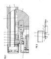
- the side guide elements of the drop bar 5 can, as shown Figure 2 can be removed, as rollers 8 which are rotatably mounted on axes projecting over the end face of the drop rod 5 and which run in an assigned track 9 of the guide rails 3, whereby there is usually a lateral running clearance.
- the curtain 4 is also provided with side guide elements 10, which can be sewn or glued on. This can be, for example, a piping or something similar.
- the guide rails 3 can be provided with guide edges 11 etc. assigned to the guide means 10 of the curtain, against which lateral contact can take place.
- the guide rails 6 In the case of pergola awnings or the like, the guide rails 6 often have a comparatively long length and a large distance between them. It can happen that the weight of the curtain 4 causes the guide rails 6 to be pulled or bent inwards, as in Figure 1 is indicated by broken arrows, so that the curtain 4 bulges downwards and sags. To counteract this, a spacer device is provided, through which the guide rails 6 are spread laterally outwards against the inward force exerted by the curtain, as in Figure 1 is indicated by arrows s.
- the drop bar 5 is as follows Figure 4 can be seen, each provided with an expansion element 12 in the area of their lateral ends.
- the guide rails 6 are, as in Figure 6 is shown, in the area of the front end position of the drop bar 5, that is, in the area that the drop bar 5 reaches at the front end of its extension movement, positioned counter-spreading elements 13.
- the expansion members 12 of the drop bar 5 run onto the counter-spreading members 13 of the guide rails 6, as shown in FIG Figures 2 and 3 is visible.
- the spreading elements 12 and counter-spreading elements 13 project in a lateral direction, that is to say in a direction towards one another, which results in the desired lateral spreading of the guide rails 6 while maintaining an exact centering of the drop rod 5.
- the expansion elements 12 and counter-expansion elements 13 have according to Figures 5 and 7 starting slopes 14, 15 facing each other in the opening direction, which are arranged in front of an assigned, raised support surface 16, 17 during the opening process.
- the starting slopes initially cause a gradual lateral expansion until the support surfaces 16, 17 are in the end position lie against each other, as from the Figures 2 and 3 is visible.
- the increase in the raised support surfaces 16, 17 is adapted to the extensibility of the curtain 4 so that a taut curtain does not tear and a sagging curtain is tensioned.
- the expansion elements 12 and counter-expansion elements 13 are designed so that they can be used in mirror images on the right and left.
- the expansion elements 12 and counter-expansion elements 13 can optionally be designed symmetrically to a vertical central plane and/or symmetrically to a central longitudinal plane.
- the spreading elements 12 of the drop bar 5 are the best Figure 5 can be seen, in the area of its upper edge is provided with one or more tabs 18, here three cantilevered on the drop bar side, each of which is assigned an engagement recess 19 adjacent to the upper edge of the associated end face of the drop bar 5.
- the expansion element 12 is therefore designed symmetrically to a vertical central plane, so that the tabs 18 also have a corresponding symmetry.
- the expansion elements 12 has according to Figure 4 one screw 20 each is provided.
- the expansion element 12 is according to Figure 5 a lead-through recess 21 assigned to the screw 20. This is located in the area of the vertical center plane.
- the expansion elements 12 can accordingly be turned by 180° for the left and right around the vertical center plane, which acts as an axis of symmetry, each time as shown in FIG Figures 2 and 3 As can be seen, only one starting slope 14 and the adjacent support surface 16 come into operation.
- the counter-spreading elements 13 assigned to the guide rails 6 are in accordance with the example shown Figure 7 designed symmetrically to its central longitudinal plane. Accordingly, the counter-spreading elements 13 only need one starting slope 15 with an adjacent support surface 17.
- a screw 22 is also provided, to which a feed-through recess 23 of the counter-spreading element 13 is assigned. This is located in the area of the central longitudinal plane that serves as a line of symmetry.
- the counter-spreading elements 13 can also simply be rotated by 180° around their line of symmetry.
- the expansion elements 12 are according to Figure 4 simply placed on the end faces of the drop bar 5, which are formed here by side caps.
- the counter-spreading elements 13 each have one in the area of the guide rails 6 Figure 6 indicated inner groove 24 is assigned, in which the counter-spreading element 13 can be received and fixed therein at the desired position.
- the embodiment of the expansion and counter-expansion elements provided to form the spacer device shown in the drawing and described above is a particularly favorable embodiment.
- registration is not limited to this. So it would also be easily conceivable to design the spreading and/or counter-spreading elements as roller or sliding elements that run on one another or as a roller or sliding element that runs on a stationary jaw etc. or, conversely, as a sliding element etc. that runs on a stationary roller etc.
- the use of a rocker or spring etc. would also be conceivable.
Landscapes
- Engineering & Computer Science (AREA)
- Architecture (AREA)
- Civil Engineering (AREA)
- Structural Engineering (AREA)
- Curtains And Furnishings For Windows Or Doors (AREA)
- Tents Or Canopies (AREA)
Claims (10)
- Store, en particulier store de pergola, comprenant une toile (4) apte à être retirée d'un caisson de store (2) et dont l'extrémité avant est montée sur une barre de chute (5), ainsi que des rails de guidage latéraux (6) qui s'étendent à partir du caisson de store (2) et sont reçus chacun, de préférence au niveau de leurs extrémités avant, sur un support (7) associé et dans lesquels sont guidées la toile (4) et la barre de chute (5) et auxquels est associé un dispositif d'écartement, caractérisé par le fait que, pour former ledit dispositif d'écartement, la barre de chute (5) est pourvue d'organes écarteurs (12) faisant saillie latéralement et montés à ses extrémités latérales, et les rails de guidage (6) sont pourvus de contre-organes écarteurs (13) qui font saillie vers l'intérieur et sont positionnés au niveau de la position finale avant de la barre de chute (5) et sur lesquels les organes écarteurs (12) de la barre de chute (5) montent lorsque la position finale avant est atteinte, dans lequel les contre-organes écarteurs (13) et les organes écarteurs (12) montant sur ceux-ci forment un dispositif écarteur latéral d'où résulte un écartement latéral souhaité des rails de guidage (6).
- Store selon la revendication 1, caractérisé par le fait que les organes écarteurs (12) et les contre-organes écarteurs (13) qui montent les uns sur les autres présentent des pentes de montée (14, 15) montrant les unes vers les autres qui sont respectivement disposées en amont d'une surface d'appui (16, 17) surélevée associée.
- Store selon l'une quelconque des revendications précédentes, caractérisé par le fait que les organes écarteurs (12) et/ou les contre-organes écarteurs (13) sont conçus de manière symétrique par rapport à un plan central vertical.
- Store selon l'une quelconque des revendications précédentes, caractérisé par le fait que les organes écarteurs (12) et/ou les contre-organes écarteurs (13) sont conçus de manière symétrique par rapport à un plan longitudinal central.
- Store selon la revendication 3, caractérisé par le fait qu'au moins les organes écarteurs (12) de la barre de chute (5) sont conçus de manière symétrique par rapport à leur plan central vertical et présentent deux pentes de montée (14) latérales inclinées l'une contre l'autre qui se terminent sur une surface d'appui (16) associée.
- Store selon la revendication 4, caractérisé par le fait qu'au moins les contre-organes écarteurs (13) des rails de guidage (6) sont conçus de manière symétrique par rapport à leur plan longitudinal central et ne présentent qu'une seule surface d'appui (17) avec une pente de montée (15) adjacente.
- Store selon la revendication 5, caractérisé par le fait que les organes écarteurs (12) de la barre de chute (5) présentent un évidement de passage (21) qui est associé à un organe de fixation et qui est prévu au niveau leur plan transversal central.
- Store selon la revendication 6, caractérisé par le fait que les contre-organes écarteurs (13) des rails de guidage (6) présentent un évidement de passage (23) qui est associé à un organe de fixation et qui est prévu au niveau de leur plan longitudinal central.
- Store selon la revendication 5, caractérisé par le fait que les organes écarteurs (12) de la barre de chute (5) présentent, au moins au niveau de leur bord supérieur, au moins une, de préférence plusieurs pattes (18) qui sont en saillie côté barre de chute et auxquelles est associé respectivement un évidement d'engagement (19) adjacent au bord supérieur de la face frontale associée de la barre de chute (5).
- Store selon la revendication 6, caractérisé par le fait que les contre-organes écarteurs (13) des rails de guidage (6) sont placés dans une rainure intérieure (24) respectivement associée des rails de guidage (6).
Applications Claiming Priority (1)
| Application Number | Priority Date | Filing Date | Title |
|---|---|---|---|
| DE202021100945.4U DE202021100945U1 (de) | 2021-02-25 | 2021-02-25 | Markise |
Publications (2)
| Publication Number | Publication Date |
|---|---|
| EP4050177A1 EP4050177A1 (fr) | 2022-08-31 |
| EP4050177B1 true EP4050177B1 (fr) | 2023-11-08 |
Family
ID=75485952
Family Applications (1)
| Application Number | Title | Priority Date | Filing Date |
|---|---|---|---|
| EP21020624.9A Active EP4050177B1 (fr) | 2021-02-25 | 2021-12-08 | Store |
Country Status (3)
| Country | Link |
|---|---|
| EP (1) | EP4050177B1 (fr) |
| DE (1) | DE202021100945U1 (fr) |
| ES (1) | ES2968170T3 (fr) |
Family Cites Families (3)
| Publication number | Priority date | Publication date | Assignee | Title |
|---|---|---|---|---|
| WO2011101879A1 (fr) * | 2010-02-22 | 2011-08-25 | Corradi S.P.A. | Dispositif de verrouillage mécanique, particulièrement pour des rideaux qui coulissent sur des glissières et analogues |
| DE102014004289A1 (de) | 2014-03-26 | 2015-10-01 | Warema Renkhoff Se | Verschattungsanlage mit Führungsschienen und Verstärkungsprofil |
| IT201700102040U1 (it) * | 2017-09-12 | 2019-03-12 | Gibus Spa | Tenda ad avvolgimento |
-
2021
- 2021-02-25 DE DE202021100945.4U patent/DE202021100945U1/de active Active
- 2021-12-08 EP EP21020624.9A patent/EP4050177B1/fr active Active
- 2021-12-08 ES ES21020624T patent/ES2968170T3/es active Active
Also Published As
| Publication number | Publication date |
|---|---|
| DE202021100945U1 (de) | 2021-03-29 |
| ES2968170T3 (es) | 2024-05-08 |
| EP4050177A1 (fr) | 2022-08-31 |
Similar Documents
| Publication | Publication Date | Title |
|---|---|---|
| CH682247A5 (fr) | ||
| AT401603B (de) | Schubladenführung mit auszugschiene | |
| EP0778379A1 (fr) | Store à rappel positif avec ressorts se déplaçant le long de celui-ci | |
| DE4402964B4 (de) | Gelenkarmmarkise | |
| EP4050177B1 (fr) | Store | |
| DE3841139C2 (de) | Sonnenschutzanlage für flächige Glasabdeckungen, insbesondere Wintergartendächer | |
| EP3583283B1 (fr) | Porte | |
| AT503260A1 (de) | Sektionaltor | |
| DE102009025120A1 (de) | Führungsvorrichtung für eine Vorhangabdunkelungsvorrichtung | |
| CH678212A5 (fr) | ||
| DE19547587C2 (de) | Rolladen für asymmetrische Öffnungen | |
| DE19716196C1 (de) | Markise oder Rollo | |
| EP1122401A2 (fr) | Store à rouleau | |
| CH677259A5 (fr) | ||
| DE4015995A1 (de) | Solarbeschattung | |
| DE19814577C1 (de) | Sonnenschutzanlage | |
| DE3508918A1 (de) | Sonnenschutzvorrichtung | |
| DE3728913A1 (de) | Vorrichtung fuer langbahnige markisen mit schienenfuehrung | |
| DE102019132564B4 (de) | Positioniereinrichtung und Sonnen-oder Blickschutzeinrichtung mit einer solchen Positioniereinrichtung | |
| DE19700757C2 (de) | Gegenzugmarkise | |
| EP3388612B1 (fr) | Dispositif et procédé de recouvrement d'une zone de bâtiment, en particulier une fenêtre d'un bâtiment | |
| DE202017104052U1 (de) | Laufschienenanordnung für ein Sektionaltor | |
| DE19501045C2 (de) | Führungsrolle zur Befestigung am unteren Rand eines Schiebetores oder dergl., insbesondere für eine Garage | |
| DE102020007655A1 (de) | Markise und Verfahren zur Montage einer solchen Markise | |
| DE19820933A1 (de) | Rollo |
Legal Events
| Date | Code | Title | Description |
|---|---|---|---|
| PUAI | Public reference made under article 153(3) epc to a published international application that has entered the european phase |
Free format text: ORIGINAL CODE: 0009012 |
|
| STAA | Information on the status of an ep patent application or granted ep patent |
Free format text: STATUS: THE APPLICATION HAS BEEN PUBLISHED |
|
| AK | Designated contracting states |
Kind code of ref document: A1 Designated state(s): AL AT BE BG CH CY CZ DE DK EE ES FI FR GB GR HR HU IE IS IT LI LT LU LV MC MK MT NL NO PL PT RO RS SE SI SK SM TR |
|
| STAA | Information on the status of an ep patent application or granted ep patent |
Free format text: STATUS: REQUEST FOR EXAMINATION WAS MADE |
|
| 17P | Request for examination filed |
Effective date: 20220831 |
|
| RBV | Designated contracting states (corrected) |
Designated state(s): AL AT BE BG CH CY CZ DE DK EE ES FI FR GB GR HR HU IE IS IT LI LT LU LV MC MK MT NL NO PL PT RO RS SE SI SK SM TR |
|
| GRAP | Despatch of communication of intention to grant a patent |
Free format text: ORIGINAL CODE: EPIDOSNIGR1 |
|
| STAA | Information on the status of an ep patent application or granted ep patent |
Free format text: STATUS: GRANT OF PATENT IS INTENDED |
|
| RIC1 | Information provided on ipc code assigned before grant |
Ipc: E04F 10/06 20060101AFI20230725BHEP |
|
| INTG | Intention to grant announced |
Effective date: 20230814 |
|
| GRAS | Grant fee paid |
Free format text: ORIGINAL CODE: EPIDOSNIGR3 |
|
| GRAA | (expected) grant |
Free format text: ORIGINAL CODE: 0009210 |
|
| STAA | Information on the status of an ep patent application or granted ep patent |
Free format text: STATUS: THE PATENT HAS BEEN GRANTED |
|
| AK | Designated contracting states |
Kind code of ref document: B1 Designated state(s): AL AT BE BG CH CY CZ DE DK EE ES FI FR GB GR HR HU IE IS IT LI LT LU LV MC MK MT NL NO PL PT RO RS SE SI SK SM TR |
|
| REG | Reference to a national code |
Ref country code: GB Ref legal event code: FG4D Free format text: NOT ENGLISH |
|
| REG | Reference to a national code |
Ref country code: CH Ref legal event code: EP |
|
| P01 | Opt-out of the competence of the unified patent court (upc) registered |
Effective date: 20231024 |
|
| REG | Reference to a national code |
Ref country code: DE Ref legal event code: R096 Ref document number: 502021001881 Country of ref document: DE |
|
| REG | Reference to a national code |
Ref country code: IE Ref legal event code: FG4D Free format text: LANGUAGE OF EP DOCUMENT: GERMAN |
|
| REG | Reference to a national code |
Ref country code: NL Ref legal event code: FP |
|
| PGFP | Annual fee paid to national office [announced via postgrant information from national office to epo] |
Ref country code: FR Payment date: 20231228 Year of fee payment: 3 Ref country code: DE Payment date: 20231231 Year of fee payment: 3 |
|
| REG | Reference to a national code |
Ref country code: GR Ref legal event code: EP Ref document number: 20230402592 Country of ref document: GR Effective date: 20240209 |
|
| REG | Reference to a national code |
Ref country code: LT Ref legal event code: MG9D |
|
| PGFP | Annual fee paid to national office [announced via postgrant information from national office to epo] |
Ref country code: BE Payment date: 20231228 Year of fee payment: 3 |
|
| PGFP | Annual fee paid to national office [announced via postgrant information from national office to epo] |
Ref country code: GR Payment date: 20240105 Year of fee payment: 3 |
|
| PG25 | Lapsed in a contracting state [announced via postgrant information from national office to epo] |
Ref country code: IS Free format text: LAPSE BECAUSE OF FAILURE TO SUBMIT A TRANSLATION OF THE DESCRIPTION OR TO PAY THE FEE WITHIN THE PRESCRIBED TIME-LIMIT Effective date: 20240308 |
|
| PG25 | Lapsed in a contracting state [announced via postgrant information from national office to epo] |
Ref country code: LT Free format text: LAPSE BECAUSE OF FAILURE TO SUBMIT A TRANSLATION OF THE DESCRIPTION OR TO PAY THE FEE WITHIN THE PRESCRIBED TIME-LIMIT Effective date: 20231108 |
|
| PGFP | Annual fee paid to national office [announced via postgrant information from national office to epo] |
Ref country code: ES Payment date: 20240130 Year of fee payment: 3 |
|
| PG25 | Lapsed in a contracting state [announced via postgrant information from national office to epo] |
Ref country code: LT Free format text: LAPSE BECAUSE OF FAILURE TO SUBMIT A TRANSLATION OF THE DESCRIPTION OR TO PAY THE FEE WITHIN THE PRESCRIBED TIME-LIMIT Effective date: 20231108 Ref country code: IS Free format text: LAPSE BECAUSE OF FAILURE TO SUBMIT A TRANSLATION OF THE DESCRIPTION OR TO PAY THE FEE WITHIN THE PRESCRIBED TIME-LIMIT Effective date: 20240308 Ref country code: BG Free format text: LAPSE BECAUSE OF FAILURE TO SUBMIT A TRANSLATION OF THE DESCRIPTION OR TO PAY THE FEE WITHIN THE PRESCRIBED TIME-LIMIT Effective date: 20240208 Ref country code: PT Free format text: LAPSE BECAUSE OF FAILURE TO SUBMIT A TRANSLATION OF THE DESCRIPTION OR TO PAY THE FEE WITHIN THE PRESCRIBED TIME-LIMIT Effective date: 20240308 |
|
| REG | Reference to a national code |
Ref country code: ES Ref legal event code: FG2A Ref document number: 2968170 Country of ref document: ES Kind code of ref document: T3 Effective date: 20240508 |