EP4047207B1 - Kolbenpumpenanordnung für ein bremssystem und steuerverfahren dafür - Google Patents
Kolbenpumpenanordnung für ein bremssystem und steuerverfahren dafür Download PDFInfo
- Publication number
- EP4047207B1 EP4047207B1 EP20876696.4A EP20876696A EP4047207B1 EP 4047207 B1 EP4047207 B1 EP 4047207B1 EP 20876696 A EP20876696 A EP 20876696A EP 4047207 B1 EP4047207 B1 EP 4047207B1
- Authority
- EP
- European Patent Office
- Prior art keywords
- piston
- lead screw
- follower
- planetary
- transmission assembly
- Prior art date
- Legal status (The legal status is an assumption and is not a legal conclusion. Google has not performed a legal analysis and makes no representation as to the accuracy of the status listed.)
- Active
Links
Images

Classifications
-
- B—PERFORMING OPERATIONS; TRANSPORTING
- B60—VEHICLES IN GENERAL
- B60T—VEHICLE BRAKE CONTROL SYSTEMS OR PARTS THEREOF; BRAKE CONTROL SYSTEMS OR PARTS THEREOF, IN GENERAL; ARRANGEMENT OF BRAKING ELEMENTS ON VEHICLES IN GENERAL; PORTABLE DEVICES FOR PREVENTING UNWANTED MOVEMENT OF VEHICLES; VEHICLE MODIFICATIONS TO FACILITATE COOLING OF BRAKES
- B60T13/00—Transmitting braking action from initiating means to ultimate brake actuator with power assistance or drive; Brake systems incorporating such transmitting means, e.g. air-pressure brake systems
- B60T13/10—Transmitting braking action from initiating means to ultimate brake actuator with power assistance or drive; Brake systems incorporating such transmitting means, e.g. air-pressure brake systems with fluid assistance, drive, or release
- B60T13/12—Transmitting braking action from initiating means to ultimate brake actuator with power assistance or drive; Brake systems incorporating such transmitting means, e.g. air-pressure brake systems with fluid assistance, drive, or release the fluid being liquid
- B60T13/16—Transmitting braking action from initiating means to ultimate brake actuator with power assistance or drive; Brake systems incorporating such transmitting means, e.g. air-pressure brake systems with fluid assistance, drive, or release the fluid being liquid using pumps directly, i.e. without interposition of accumulators or reservoirs
- B60T13/20—Transmitting braking action from initiating means to ultimate brake actuator with power assistance or drive; Brake systems incorporating such transmitting means, e.g. air-pressure brake systems with fluid assistance, drive, or release the fluid being liquid using pumps directly, i.e. without interposition of accumulators or reservoirs with control of pump driving means
-
- B—PERFORMING OPERATIONS; TRANSPORTING
- B60—VEHICLES IN GENERAL
- B60T—VEHICLE BRAKE CONTROL SYSTEMS OR PARTS THEREOF; BRAKE CONTROL SYSTEMS OR PARTS THEREOF, IN GENERAL; ARRANGEMENT OF BRAKING ELEMENTS ON VEHICLES IN GENERAL; PORTABLE DEVICES FOR PREVENTING UNWANTED MOVEMENT OF VEHICLES; VEHICLE MODIFICATIONS TO FACILITATE COOLING OF BRAKES
- B60T11/00—Transmitting braking action from initiating means to ultimate brake actuator without power assistance or drive or where such assistance or drive is irrelevant
- B60T11/10—Transmitting braking action from initiating means to ultimate brake actuator without power assistance or drive or where such assistance or drive is irrelevant transmitting by fluid means, e.g. hydraulic
- B60T11/16—Master control, e.g. master cylinders
-
- B—PERFORMING OPERATIONS; TRANSPORTING
- B60—VEHICLES IN GENERAL
- B60T—VEHICLE BRAKE CONTROL SYSTEMS OR PARTS THEREOF; BRAKE CONTROL SYSTEMS OR PARTS THEREOF, IN GENERAL; ARRANGEMENT OF BRAKING ELEMENTS ON VEHICLES IN GENERAL; PORTABLE DEVICES FOR PREVENTING UNWANTED MOVEMENT OF VEHICLES; VEHICLE MODIFICATIONS TO FACILITATE COOLING OF BRAKES
- B60T13/00—Transmitting braking action from initiating means to ultimate brake actuator with power assistance or drive; Brake systems incorporating such transmitting means, e.g. air-pressure brake systems
- B60T13/74—Transmitting braking action from initiating means to ultimate brake actuator with power assistance or drive; Brake systems incorporating such transmitting means, e.g. air-pressure brake systems with electrical assistance or drive
- B60T13/745—Transmitting braking action from initiating means to ultimate brake actuator with power assistance or drive; Brake systems incorporating such transmitting means, e.g. air-pressure brake systems with electrical assistance or drive acting on a hydraulic system, e.g. a master cylinder
-
- F—MECHANICAL ENGINEERING; LIGHTING; HEATING; WEAPONS; BLASTING
- F04—POSITIVE - DISPLACEMENT MACHINES FOR LIQUIDS; PUMPS FOR LIQUIDS OR ELASTIC FLUIDS
- F04B—POSITIVE-DISPLACEMENT MACHINES FOR LIQUIDS; PUMPS
- F04B17/00—Pumps characterised by combination with, or adaptation to, specific driving engines or motors
- F04B17/03—Pumps characterised by combination with, or adaptation to, specific driving engines or motors driven by electric motors
-
- F—MECHANICAL ENGINEERING; LIGHTING; HEATING; WEAPONS; BLASTING
- F04—POSITIVE - DISPLACEMENT MACHINES FOR LIQUIDS; PUMPS FOR LIQUIDS OR ELASTIC FLUIDS
- F04B—POSITIVE-DISPLACEMENT MACHINES FOR LIQUIDS; PUMPS
- F04B49/00—Control, e.g. of pump delivery, or pump pressure of, or safety measures for, machines, pumps, or pumping installations, not otherwise provided for, or of interest apart from, groups F04B1/00 - F04B47/00
-
- F—MECHANICAL ENGINEERING; LIGHTING; HEATING; WEAPONS; BLASTING
- F04—POSITIVE - DISPLACEMENT MACHINES FOR LIQUIDS; PUMPS FOR LIQUIDS OR ELASTIC FLUIDS
- F04B—POSITIVE-DISPLACEMENT MACHINES FOR LIQUIDS; PUMPS
- F04B9/00—Piston machines or pumps characterised by the driving or driven means to or from their working members
- F04B9/02—Piston machines or pumps characterised by the driving or driven means to or from their working members the means being mechanical
-
- F—MECHANICAL ENGINEERING; LIGHTING; HEATING; WEAPONS; BLASTING
- F04—POSITIVE - DISPLACEMENT MACHINES FOR LIQUIDS; PUMPS FOR LIQUIDS OR ELASTIC FLUIDS
- F04B—POSITIVE-DISPLACEMENT MACHINES FOR LIQUIDS; PUMPS
- F04B49/00—Control, e.g. of pump delivery, or pump pressure of, or safety measures for, machines, pumps, or pumping installations, not otherwise provided for, or of interest apart from, groups F04B1/00 - F04B47/00
- F04B49/12—Control, e.g. of pump delivery, or pump pressure of, or safety measures for, machines, pumps, or pumping installations, not otherwise provided for, or of interest apart from, groups F04B1/00 - F04B47/00 by varying the length of stroke of the working members
- F04B49/14—Adjusting abutments located in the path of reciprocation
-
- F—MECHANICAL ENGINEERING; LIGHTING; HEATING; WEAPONS; BLASTING
- F16—ENGINEERING ELEMENTS AND UNITS; GENERAL MEASURES FOR PRODUCING AND MAINTAINING EFFECTIVE FUNCTIONING OF MACHINES OR INSTALLATIONS; THERMAL INSULATION IN GENERAL
- F16H—GEARING
- F16H25/00—Gearings comprising primarily only cams, cam-followers and screw-and-nut mechanisms
- F16H25/18—Gearings comprising primarily only cams, cam-followers and screw-and-nut mechanisms for conveying or interconverting oscillating or reciprocating motions
- F16H25/20—Screw mechanisms
- F16H2025/2062—Arrangements for driving the actuator
- F16H2025/2087—Arrangements for driving the actuator using planetary gears
Definitions
- This application belongs to the field of hydraulic brake technologies, and in particular, to a piston pump group for a brake system and a control method thereof.
- a piston pump In a hydraulic vehicle brake system, a piston pump is used for service braking, and/or slip adjustment.
- the piston pump generates brake pressure for delivering delivery brake fluid from a wheel brake to the wheel brake after the pressure drops, to increase the wheel brake pressure again, or for delivering the brake fluid in a direction of a main brake cylinder during slip adjustment.
- a position at which a piston stops is difficult to determine. Therefore, when next braking is required, a braking operation is performed from a position at which the piston stops currently, which cannot ensure that the brake pressure generated by the piston pump reaches an expected effect, so that driving safety is affected.
- Document US 9 982 662 B2 discloses a pressure generator for a hydraulic vehicle brake system including a piston-cylinder unit, a piston, a ball screw drive configured to move the piston, an electric hollow-shaft motor that surrounds and is configured to drive the ball screw drive, and a planetary gear set configured to transmit a rotational movement of the hollow-shaft motor to the ball screw drive.
- the generator also includes a flange part, a sleeve, and an axial needle-roller bearing.
- the flange part has a tubular collar configured to axially guide the piston in a movable fashion therein.
- the sleeve has a flange configured as a counterbearing which is attached to an interior of the tubular collar, and is further configured to support the bearing.
- the bearing is configured to rotatably mount and axially support the ball screw drive.
- Document US 2017/137005 A1 discloses a hydraulics block having a piston-cylinder unit that can be driven by an electric motor via a gear in order to generate a brake pressure for a hydraulic non-muscular-energy vehicle brake system.
- An annular cavity is provided which encloses a piston of the piston-cylinder unit inside a cylinder, as a leakage chamber which communicates with a reservoir. Possible drag leakage is carried away in this manner.
- An end shield situated between the electric motor and the gear prevents lubricant or leakage from entering the electric motor.
- Document US 2018/345934 A1 discloses a piston pump assembly for a hydraulic vehicle brake system having an electric motor and, coaxially to that, a planetary gear, a ball-screw drive and a piston-cylinder unit, in which a piston is connected in a rotatably and axially fixed manner to a spindle of the ball-screw drive and guiding the piston in a rotatably fixed manner in the cylinder, so that the spindle is retained in a rotatably fixed manner.
- the planetary gear is mounted in a pot-shaped planetary-gear housing that is disposed on a ball bearing which is used for a rotational mounting of a spindle nut on a cylinder of the piston-cylinder unit.
- This application aims to resolve at least one of the foregoing problems, and provides a piston pump group for a brake system and a control method thereof, which can better achieve an effect of pumping out high-pressure fluid, provide stable brake pressure for the brake system, and have good operating stability.
- a piston pump group for a brake system including: a piston, a pump body provided with an operating chamber, and a transmission mechanism used for driving the piston to move in the operating chamber, where the transmission mechanism includes a lead screw transmission assembly, a follower, and a planetary gear assembly used for transmitting power to the lead screw transmission assembly, the follower is fixedly connected to the piston, the lead screw transmission assembly is used for driving the follower to move relative to the operating chamber, and a limiting member used for limiting the movement of the follower is disposed between the lead screw transmission assembly and the follower.
- the planetary gear assembly includes a drive wheel, an inner gear ring, a planetary cover and a plurality of planetary gears, the plurality of planetary gears are respectively meshed with the inner gear ring, the planetary gears are located between the drive wheel and the inner gear ring, the drive wheel is meshed with the planetary gears respectively, and the planetary cover is connected to the inner gear ring through a positioning structure.
- the positioning structure includes a groove disposed in a circumferential direction of an inner ring of the planetary cover and a protrusion disposed in a circumferential direction of an outer ring of the inner gear ring and used for cooperating with the groove, or the positioning structure includes a protrusion disposed in the circumferential direction of the inner ring of the planetary cover and a groove disposed in the circumferential direction of the outer ring of the inner gear ring and used for cooperating with the protrusion.
- the lead screw transmission assembly includes a bearing outer ring, a bearing inner ring, a bearing holder, and a lead screw
- the bearing outer ring is sleeved outside the bearing inner ring
- the bearing holder is disposed between the bearing outer ring and the bearing inner ring
- the bearing holder is provided with a plurality of accommodation cavities used for accommodating ball bearings
- the bearing inner ring is fixedly connected to one end of the lead screw
- the follower is threadably connected to the lead screw
- the planetary gears are disposed on a top surface of the bearing inner ring through a planetary pin
- the planetary cover is fixedly connected to the bearing outer ring.
- the lead screw and the bearing inner ring are of an integrally formed structure.
- the lead screw is of a hollow structure, and a through hole is disposed in an axial direction of the lead screw.
- the limiting member is a limiting pin
- the limiting pin penetrates through the bearing inner ring to form a collision portion
- a collision structure used for performing contact limit with the collision portion is disposed on the follower.
- This application further provides a control method, used for controlling the foregoing piston pump group for a brake system, and the control method includes zero point calibration of a piston, and includes the following steps:
- control method further includes: controlling the piston to automatically stop the axial movement in a lower stop point after step S11, where the lower stop point is a position at a preset distance from an inner wall of the bottom of a pump body.
- the step of controlling the piston to automatically stop the axial movement in a lower stop point includes:
- the piston pump group for a brake system and the control method thereof provided by this application have the following beneficial effects:
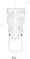
- a piston pump group for a brake system includes a piston 2, a transmission mechanism 3, and a pump body 1 provided with an operating chamber.
- the transmission mechanism 3 is used for driving the piston 2 to reciprocate in the operating chamber to change an operating volume of the operating chamber, and inhale liquid or discharge the liquid with pressure.
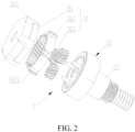
- the transmission mechanism 3 includes a lead screw transmission assembly 32, a follower 33 and a planetary gear assembly 31.
- the planetary gear assembly 31 is used for transmitting power of a driving element to the lead screw transmission assembly 32, so that the lead screw transmission assembly 32 drives the follower 33 to move relative to the operating chamber in the pump body 1.
- the follower 33 is fixedly connected to the piston 2, so that the piston 2 can move with the follower 33 (that is, the piston 2 and the follower 33 are used as a whole).
- a limiting member 34 used for limiting the movement of the follower 33 is disposed between the lead screw transmission assembly 32 and the follower 33, which can prevent the follower 33 (the piston 2) from colliding and interfering with another component when the follower 33 (the piston 2) moves upward (the operating volume of the operating chamber becomes larger).
- zero point calibration of the piston 2 can also be realized by using the limiting member 34.
- the operating volume of the operating chamber is the largest (that is, the piston 2 is at a zero point position in this case), to ensure that fluid discharged from the piston pump group has sufficient pressure to provide stable brake pressure for the brake system.
- the driving element operates to drive the planetary gear assembly 31 to rotate, to drive the lead screw transmission assembly 32 to rotate, so that the follower 33 (the piston 2) moves close to the limiting member 34 or away from the limiting member 34 with the rotation of the lead screw transmission assembly 32.
- the movement of the piston 2 changes the operating volume of the operating chamber.
- the operating chamber of the pump body 1 may be connected to an inhalation valve port and a discharge valve port, and change of the volume of the operating chamber generates a pressure difference, so that liquid (hydraulic oil) is inhaled into the operating chamber through the inhalation valve port, or the liquid (the hydraulic oil) is discharged from the operating chamber through the discharge valve port.
- liquid hydroaulic oil
- the piston pump group for a brake system further includes the driving element used for providing the power.
- the driving element is a motor
- the motor is connected to a motor controller and a rotation number sensor.
- the motor controller is used for controlling stop and operation of the motor.
- the operation of the motor includes clockwise rotation and counterclockwise rotation of the motor.
- the rotation sensor is used for obtaining a rotation number of an output shaft.
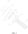
- the follower 33 may be connected and fixed to the piston 2 through a threaded structure, that is, the follower 33 is fixed to the piston 2 in a manner of threaded connection, where the threaded structure includes an external thread 331 disposed in a circumferential direction of an outer side of the follower 33 and an internal thread disposed in a circumferential direction of an inner side of the piston 2 (namely, an inner wall of the piston 2), and the external thread 331 of the follower 33 cooperates with the internal thread of the piston 2, to realize connection and fixation of the follower 33 and the piston 2.
- the follower 33 is fixed to the piston 2 by using the threaded connection, which can ensure that the follower 33, the piston 2, and the operating chamber have good coaxiality, and can also ensure the air tightness of the operating chamber, to provide the stable brake pressure for the brake system, and ensure the driving safety.
- the follower 33 is threadly connected to the piston 2, which increases a force bearing area of the two, so that a problem of stress concentration can be well avoided, thereby improving a service life of the piston pump group.
- the planetary gear assembly 31 includes a drive wheel (not shown in the figure), an inner gear ring 312, a planetary cover 311, and a plurality of planetary gears 313 with the same structure.
- the planetary gears 313 are meshed with the inner gear ring 312 respectively, the planetary gears 313 are located between the drive wheel and the inner gear ring 312, and the planetary gears 313 are also meshed with the drive wheel respectively.
- the drive wheel is used as a sun wheel and is connected to the output shaft of the motor, to transmit the power of the motor to the planetary gears 313, to drive the planetary gears 313 to rotate.
- the planetary cover 311 is sleeved on the inner gear ring 312, and is connected to the inner gear ring 312 through a positioning structure, to fix the inner gear ring 312.
- the planetary gear assembly 31 has advantages of a small size, large bearing capability, and stable operation.
- the drive wheel, the planetary gears 313, and the inner gear ring 312 may be of a helical tooth structure, which has characteristics of good meshing, stable transmission, and low noise.
- coincidence of helical gears is great, which reduces payloads of each pair of gears and improves bearing capability of the gears.
- the drive wheel, the planetary gears 313, and the inner gear ring 312 may also be of a straight tooth structure.
- the positioning structure includes a groove 3111 disposed in a circumferential direction of an inner ring of the planetary cover 311 and a protrusion 3121 disposed in a circumferential direction of an outer ring of the inner gear ring 312 and used for cooperating with the groove 3111, or the positioning structure includes a protrusion disposed in the circumferential direction of the inner ring of the planetary cover 311 and a groove disposed in the circumferential direction of the outer ring of the inner gear ring 312 and used for cooperating with the protrusion.
- the protrusion 3121 and the groove 3111 use an interference fit, and positioning connection is performed through the protrusion 3121 and the groove 3111, so that assembly connection of the planetary cover 311 and the inner gear ring 312 is easy to realize.
- protrusions 3121 there may be a plurality of protrusions 3121, and the protrusions 3121 are distributed on the inner gear ring 312 in the form of the circumferential array.
- cross-sections of the protrusions 3121 may be of a structure of a rectangle, a triangle, a trapezoid, an arc, or the like.
- a quantity of grooves 3111 and cross-sections thereof correspond to the protrusions 3121.
- the lead screw transmission assembly 32 includes a bearing outer ring 321, a bearing inner ring 322, a bearing holder 323 and a lead screw 324.
- the bearing outer ring 321 is sleeved outside the bearing inner ring 322, and the bearing holder 323 is disposed between the bearing outer ring 321 and the bearing inner ring 322.
- the bearing holder 323 is provided with a plurality of accommodation cavities 3231 for accommodating ball bearings 325, and the bearing inner ring 322 is rollingly connected to the bearing outer ring 321 through the ball bearings 325.
- the bearing inner ring 322 is fixedly connected to one end of the lead screw 324, and the planetary gears 313 are respectively disposed on a top surface of the bearing inner ring 322 through a planetary pin 3131.
- the planetary gears 313 may rotate relative to the bearing inner ring 322 around the planetary pin 3131, and the planetary gears 313 may also rotate relative to the inner gear ring 312 simultaneously, to drive the bearing inner ring 322 (the lead screw 324) to rotate.
- the follower 33 is threadedly connected to the lead screw 324, so that the follower 33 can axially move (close to or away from the limiting member 34) relative to the lead screw 324 with the rotation of the lead screw 324.
- the planetary cover 311 is connected and fixed to the bearing outer ring 321 by welding, and the inner gear ring 312 is clamped in the planetary cover 311 by the bearing outer ring 321. It can be understood that, the planetary cover 311 may also be connected and fixed to the bearing outer ring 321 by using screws.
- the lead screw 324 and the bearing inner ring 322 are of an integrally formed structure
- cross-sections of the lead screw 324 and the bearing inner ring 322 may be T-shaped, and a center of the bearing inner ring 322 coincides with a central axis of the lead screw 324.
- the structure has high strength, and can also prevent the bearing inner ring 322 from easily deforming when the lead screw 324 and the bearing inner ring 322 are press-fitted by interference, so that the bearing inner ring 322 rolls smoothly, and reliability of the overall operation of the piston pump group is ensured.
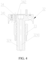
- the lead screw 324 is of a hollow structure, and a through hole 3241 is disposed in an axial direction of the lead screw 324.
- the through hole 3241 and the lead screw 324 are coaxially disposed, that is, a central axis of the through hole 3241 coincides with the central axis of the lead screw 324, to ensure that a center of mass of the lead screw 324 is on the central axis during rotation.
- the lead screw 324 is designed to the hollow structure.
- a diameter of the through hole 3241 is 1/5 to 1/2 of a diameter of the lead screw 324.
- the bearing outer ring 321 is connected to the pump body 1 through a connecting member 35, and the planetary gear assembly 31 and the lead screw transmission assembly 32 are installed and fixed on the pump body 1.
- the bearing outer ring 321 is integrated with the pump body 1 through the connecting member 35 in a manner of press fitting by interference.
- the planetary cover 311, the inner gear ring 312, and the bearing outer ring 321 are all fixed and do not move, to support the planetary gears 313, the bearing inner ring 322, and the lead screw.
- the limiting member 34 is a limiting pin
- the limiting pin penetrates through the bearing inner ring 322
- a collision portion 342 is formed on one side of the limiting pin toward the follower 33
- a collision structure used for performing contact limit with the collision portion 342 is disposed on the follower 33.
- the movement of the follower 33 is limited by setting the limiting member 34, to prevent the follower 33 from colliding and interfering with the bearing inner ring 322 when the piston 2 returns.
- the zero point calibration of the piston 2 may also be performed by using the limiting member 34, to ensure that the piston 2 is at the zero point position each time the piston 2 operates (definition: the zero point position is a position of the piston 2 when the operating chamber is at a maximum operating volume).
- the limiting member 34 is threadedly connected to the bearing inner ring 322, and a length of the collision portion 342 may be controlled by adjusting a length of the limiting member 34 penetrating through the bearing inner ring 322, to limit a movement stroke of the piston 2 to the limiting member 34, and adjust the maximum volume of the operating chamber.
- the limiting member 34 is easy to replace after being damaged by collision.
- the follower 33 may be a nut, the external thread 331 is disposed at a lower end of an outer circumferential direction of the nut, and the collision structure may be integrally formed on a boss 341 at a top end of the nut.
- the nut the piston 2 stops moving immediately, and a current position of the piston 2 is the zero point position.
- a total length of the nut is 40.3 mm (which includes the boss 341 of 3 mm), and a length of the external thread 331 is 14 mm.
- the collision structure is mainly used for positioning the collision portion 342. Therefore, the collision structure may also be a groove disposed in a top surface of the nut.
- This application further provides a control method, used for controlling the foregoing piston pump group for a brake system, and the control method includes zero point calibration of a piston 2, that is, the piston 2 needs to be first moved to a zero point position before operation, to ensure that pressure of liquid initially discharged by the piston pump group is an expected value, and a brake effect is stable.
- this embodiment describes with reference to a motor, and specific steps are as follows:
- S10 controlling a motor to enable and rotate in a first direction, to drive a planetary gear assembly 31 to rotate in the first direction, to drive a lead screw transmission assembly 32 to rotate in the first direction, so that a follower 33 moves close to a limiting member 34 with the rotation of the lead screw transmission assembly 32, and the piston 2 moves close to the limiting member 34 with the follower 33;
- S11 generating a collision signal when a collision structure of the follower 33 is in contact with the limiting member 34; feeding back, by a rotation sensor of the motor, the collision signal to a motor controller after receiving the collision signal; and generating, by the motor controller, an instruction of stopping operation, and executing the instruction of stopping operation, so that the motor stops rotating in the first direction, so that the planetary gear assembly 31 and the lead screw transmission assembly 32 stop rotating, and then the follower 33 and the piston 2 stop axial movement, and a current position of the piston 2 is a zero point position.
- the piston 2 may alternatively stop automatically at the zero point position by means of limiting, to prevent the piston 2 from colliding with another component.
- the method further includes: controlling the piston 2 to automatically stop the axial movement in a lower stop point after step S11, where the lower stop point is a position at a preset distance from an inner wall of the bottom of a pump body 1, and specifically, to a position of the piston 2 when a distance between the piston 2 and the inner wall of the bottom of the pump body 1 (the bottom of an operating chamber) is equal to a preset distance.
- the step of controlling the piston 2 to automatically stop the axial movement in a lower stop point includes:
- step S21 determining whether the current rotation number exceeds a preset revolution threshold, to determine whether the piston 2 moves to the lower stop point, where the preset revolution threshold is the rotation number of the output shaft of the motor or the rotation number of the lead screw 324 when the piston 2 moves from the zero point position to the lower stop point; if the current rotation number of the motor or the current rotation number of the lead screw transmission assembly 32 does not exceed the preset revolution threshold, performing step S20; and if the current rotation number of the motor or the current rotation number of the lead screw transmission assembly 32 is equal to the preset revolution threshold, performing step S22; and
- the motor controller If the current rotation number of the motor or the current rotation number of the lead screw transmission assembly 32 does not exceed the preset revolution threshold, the motor controller generates an instruction of continuing operation, and executes the instruction of continuing operation, to control the motor to continuously rotate in the second direction, until the current rotation number of the motor or the current rotation number of the lead screw transmission assembly 32 is equal to the preset revolution threshold (the piston 2 moves to the lower stop point), and control the motor to stop rotating in the second direction.
- the first direction and the second direction are determined according to a rotation direction of a thread of the lead screw 324.
- the first direction is a counterclockwise direction, and the follower 33 moves upward relative to the lead screw 324; and the second direction is a clockwise direction, and the follower 33 moves downward relative to the lead screw 324.
- the thread of the lead screw 324 is left-handed, the first direction is the clockwise direction, and the follower 33 moves upward relative to the lead screw 324; and the second direction is the counterclockwise direction, and the follower 33 moves downward relative to the lead screw 324.
- the first feature being located “above” or “below” the second feature may be the first feature being in a direct contact with the second feature, or the first feature being in an indirect contact with the second feature through an intermediary.
- the first feature being located “above” the second feature may be the first feature being located directly above or obliquely above the second feature, or may simply indicate that the first feature is higher in level than the second feature.
- the first feature being located “below” the second feature may be the first feature being located directly below or obliquely below the second feature, or may simply indicate that the first feature is lower in level than the second feature.
Landscapes
- Engineering & Computer Science (AREA)
- Mechanical Engineering (AREA)
- Transportation (AREA)
- General Engineering & Computer Science (AREA)
- Reciprocating Pumps (AREA)
- Valves And Accessory Devices For Braking Systems (AREA)
Claims (10)
- Kolbenpumpengruppe für ein Bremssystem, die einen Kolben (2), einen Pumpenkörper (1), der mit einer Arbeitskammer versehen ist, und einen Übertragungsmechanismus (3) umfasst, der dazu verwendet wird, den Kolben anzutreiben, damit er sich in der Arbeitskammer bewegt, wobei der Übertragungsmechanismus eine Leitspindelübertragungsbaugruppe bzw. Leitspindelgetriebebaugruppe (32), einen Stößel bzw. Mitnehmer (33) und eine Planetengetriebebaugruppe (31) umfasst, die dazu verwendet wird, Kraft auf die Leitspindelübertragungsbaugruppe zu übertragen, der Stößel fest mit dem Kolben verbunden ist, die Leitspindelgetriebebaugruppe dazu dient, den Stößel anzutreiben, damit er sich relativ zu der Arbeitskammer bewegt, gekennzeichnet durch
ein Begrenzungselement (34), das dazu dient, die Bewegung des Stößels bzw. Mitnehmers zu begrenzen, und das zwischen der Leitspindelgetriebebaugruppe und dem Stößel bzw. Mitnehmer angeordnet ist. - Kolbenpumpengruppe für ein Bremssystem gemäß Anspruch 1, wobei die Planetengetriebebaugruppe ein Antriebsrad, einen Innenzahnkranz (312), eine Planetenabdeckung (311) und mehrere Planetenräder (313) umfasst, die mehreren Planetenräder jeweils mit dem Innenzahnkranz in Eingriff stehen, die Planetenräder zwischen dem Antriebsrad und dem Innenzahnkranz angeordnet sind, das Antriebsrad jeweils mit den Planetenrädern in Eingriff steht und die Planetenabdeckung mit dem Innenzahnkranz über eine Positionierungsstruktur verbunden ist.
- Kolbenpumpengruppe für ein Bremssystem gemäß Anspruch 2, wobei die Positionierungsstruktur eine in einer Umfangsrichtung eines Innenrings der Planetenabdeckung angeordnete Nut (3111) und einen in einer Umfangsrichtung eines Außenrings des Innenzahnradrings angeordneten Vorsprung (3121) umfasst, der zum Zusammenwirken mit der Nut verwendet wird, oder wobei die Positionierungsstruktur einen Vorsprung umfasst, der in der Umfangsrichtung des Innenrings der Planetenabdeckung angeordnet ist, und eine Nut, die in der Umfangsrichtung des Außenrings des Innenzahnradrings angeordnet ist und für das Zusammenwirken mit dem Vorsprung verwendet wird.
- Kolbenpumpengruppe für ein Bremssystem gemäß Anspruch 2 oder 3, wobei die Leitspindelgetriebebaugruppe einen Lageraußenring (321), einen Lagerinnenring (322), einen Lagerhalter (323) und eine Leitspindel (324) umfasst, der Lageraußenring außerhalb des Lagerinnenrings ummantelt ist, der Lagerhalter zwischen dem Lageraußenring und dem Lagerinnenring angeordnet ist, der Lagerhalter mit einer Vielzahl von Aufnahmehohlräumen versehen ist, die zur Aufnahme von Kugellagern verwendet werden, der Lagerinnenring fest mit einem Ende der Leitspindel verbunden ist, der Mitnehmer schraubbar mit der Leitspindel verbunden ist, die Planetenräder auf einer oberen Oberfläche des Lagerinnenrings durch einen Planetenstift (3131) angeordnet sind, und die Planetenabdeckung fest mit dem Lageraußenring verbunden ist.
- Kolbenpumpengruppe für ein Bremssystem gemäß Anspruch 4, wobei die Leitspindel und der Lagerinnenring eine einstückige Struktur aufweisen.
- Kolbenpumpengruppe für ein Bremssystem gemäß Anspruch 5, wobei die Leitspindel eine hohle Struktur aufweist und ein Durchgangsloch (3241) in einer axialen Richtung der Leitspindel angeordnet ist.
- Kolbenpumpengruppe für ein Bremssystem gemäß einem der Ansprüche 4 bis 6, wobei das Begrenzungselement ein Begrenzungsbolzen ist, der Begrenzungsbolzen den Lagerinnenring durchdringt, um einen Kollisionsabschnitt (342) zu bilden, und eine Kollisionsstruktur, die zur Durchführung der Kontaktbegrenzung mit dem Kollisionsabschnitt verwendet wird, an dem Mitnehmer angeordnet ist.
- Steuerverfahren zur Steuerung der Kolbenpumpengruppe für ein Bremssystem gemäß einem der Ansprüche 1 bis 7, wobei das Steuerverfahren eine Nullpunktkalibrierung des Kolbens (2) umfasst und die folgenden Schritte aufweist:S10: Steuern eines Motors, damit er sich in einer ersten Richtung dreht, um die Planetengetriebebaugruppe (31) anzutreiben, damit sie sich in der ersten Richtung dreht, um die Leitspindelgetriebebaugruppe (32) anzutreiben, damit sie sich in der ersten Richtung dreht, so dass sich der Mitnehmer (33) mit der Drehung der Leitspindelgetriebebaugruppe (32) nahe an das Begrenzungselement (34) bewegt, undS11: Steuern des Motors, um den Betrieb zu stoppen, wenn der Mitnehmer bzw. Stößel (33), insbesondere die Kollisionsstruktur des Stößels (33) gemäß Anspruch 7, in Kontakt mit dem Begrenzungselement (34) ist, so dass die Planetengetriebebaugruppe (31) und die Leitspindelübertragungsbaugruppe (32) aufhören, sich zu drehen, so dass der Stößel (33) und der Kolben (2) aufhören, sich axial zu bewegen, und eine aktuelle Position des Kolbens (2) eine Nullpunktposition ist.
- Steuerungsverfahren gemäß Anspruch 8, ferner umfassend: Steuern des Kolbens (2) zum automatischen Stoppen bzw. Anhalten der Axialbewegung in einem unteren Stopppunkt bzw. Anschlagspunkt nach Schritt S11, wobei der untere Stopppunkt eine Position in einem voreingestellten Abstand von einer Innenwand des Bodens eines Pumpenkörpers ist.
- Steuerungsverfahren gemäß Anspruch 9, wobei der Schritt des Steuerns des Kolbens zum automatischen Anhalten der axialen Bewegung in einem unteren Anschlagspunkt umfasst:S20: Steuern des Motors, damit er sich in einer zweiten Richtung dreht, um die Planetengetriebebaugruppe (31) anzutreiben, damit sie sich in der zweiten Richtung dreht, um die Leitspindelübertragungsbaugruppe (32) anzutreiben, damit sie sich in der zweiten Richtung dreht, so dass sich das Folgeglied bzw. der Mitnehmer (33) mit der Drehung der Leitspindelübertragungsbaugruppe (32) von dem Begrenzungselement (34) weg bewegt, und Ermitteln einer aktuellen Drehzahl des Motors oder einer aktuellen Drehzahl der Leitspindelübertragungsbaugruppe (32) in Echtzeit;S21: Bestimmen, ob die aktuelle Umdrehungszahl einen voreingestellten Umdrehungsschwellenwert überschreitet; wenn die aktuelle Umdrehungszahl den voreingestellten Umdrehungsschwellenwert nicht überschreitet, Ausführen von Schritt S20; und wenn die aktuelle Umdrehungszahl gleich dem voreingestellten Umdrehungsschwellenwert ist, Ausführen von Schritt S22; undS22: Steuerung des Motors, um die Drehung in der zweiten Richtung zu stoppen, so dass die Planetengetriebebaugruppe (31) und die Leitspindelübertragungsbaugruppe die Drehung in der zweiten Richtung stoppen, so dass der Mitnehmer (33) und der Kolben (2) die axiale Bewegung stoppen und die aktuelle Position des Kolbens (2) der untere Anschlagspunkt ist.
Applications Claiming Priority (2)
| Application Number | Priority Date | Filing Date | Title |
|---|---|---|---|
| CN201910980645.9A CN112664440B (zh) | 2019-10-16 | 2019-10-16 | 一种用于制动系统的活塞泵组及其控制方法 |
| PCT/CN2020/120884 WO2021073531A1 (zh) | 2019-10-16 | 2020-10-14 | 一种用于制动系统的活塞泵组及其控制方法 |
Publications (3)
| Publication Number | Publication Date |
|---|---|
| EP4047207A1 EP4047207A1 (de) | 2022-08-24 |
| EP4047207A4 EP4047207A4 (de) | 2022-12-07 |
| EP4047207B1 true EP4047207B1 (de) | 2025-03-26 |
Family
ID=75400330
Family Applications (1)
| Application Number | Title | Priority Date | Filing Date |
|---|---|---|---|
| EP20876696.4A Active EP4047207B1 (de) | 2019-10-16 | 2020-10-14 | Kolbenpumpenanordnung für ein bremssystem und steuerverfahren dafür |
Country Status (5)
| Country | Link |
|---|---|
| US (1) | US12263818B2 (de) |
| EP (1) | EP4047207B1 (de) |
| JP (1) | JP7420929B2 (de) |
| CN (1) | CN112664440B (de) |
| WO (1) | WO2021073531A1 (de) |
Families Citing this family (7)
| Publication number | Priority date | Publication date | Assignee | Title |
|---|---|---|---|---|
| JP7632161B2 (ja) * | 2021-08-05 | 2025-02-19 | 日本精工株式会社 | ボールねじ装置 |
| CN114046234B (zh) * | 2021-11-02 | 2023-06-13 | 万向钱潮股份有限公司 | 一种集成式制动系统的活塞泵总成 |
| CN114151406A (zh) * | 2021-11-26 | 2022-03-08 | 国焊(上海)智能科技有限公司 | 一种活塞装置 |
| CN114673642A (zh) * | 2022-03-30 | 2022-06-28 | 湖南麦格米特电气技术有限公司 | 一种活塞泵、清洗器及智能马桶 |
| DE102022205404A1 (de) * | 2022-05-30 | 2023-11-30 | Robert Bosch Gesellschaft mit beschränkter Haftung | Betätigungseinrichtung für ein Bremssystem, Bremssystem |
| CN115610396A (zh) * | 2022-11-09 | 2023-01-17 | 南京经纬达汽车科技有限公司 | 一种电液制动系统滚珠丝杠副的限位回零装置 |
| CN117182555B (zh) * | 2023-11-07 | 2024-01-26 | 万向钱潮股份公司 | 一种制动器安装方法及装置 |
Citations (1)
| Publication number | Priority date | Publication date | Assignee | Title |
|---|---|---|---|---|
| CN101169111A (zh) * | 2007-11-01 | 2008-04-30 | 王桐梅 | 一种丝杠活塞泵 |
Family Cites Families (23)
| Publication number | Priority date | Publication date | Assignee | Title |
|---|---|---|---|---|
| JPS59196586A (ja) | 1983-04-23 | 1984-11-07 | 永楽産業株式会社 | 分岐コネクタ− |
| JPS59196586U (ja) * | 1983-06-14 | 1984-12-27 | 日本フイ−ダ−工業株式会社 | 往復動ポンプ |
| US5744884A (en) * | 1995-10-17 | 1998-04-28 | Applied Precision, Inc. | Liner motion micropositioning apparatus and method |
| US6102828A (en) * | 1998-06-03 | 2000-08-15 | Halliburton Energy Services, Inc. | Electrohydraulic control unit |
| DE10142644A1 (de) * | 2001-08-31 | 2003-04-03 | Lucas Automotive Gmbh | Motorbetätigbare Scheibenbremse |
| JP2005114042A (ja) | 2003-10-08 | 2005-04-28 | Honda Motor Co Ltd | 電動駐車ブレーキ装置 |
| CN100480532C (zh) * | 2004-06-15 | 2009-04-22 | Pbr澳大利亚有限责任公司 | 致动机构及制动组件 |
| JP5404448B2 (ja) | 2010-01-25 | 2014-01-29 | 曙ブレーキ工業株式会社 | ドラム式電動駐車ブレーキ装置 |
| JP2012007674A (ja) | 2010-06-24 | 2012-01-12 | Hitachi Automotive Systems Ltd | ディスクブレーキ |
| FR2974155B1 (fr) * | 2011-04-12 | 2015-12-18 | Pulssar Technologies | Pompe a piston comportant un guidage a plat. |
| JP2013099840A (ja) | 2011-10-19 | 2013-05-23 | Nsk Ltd | ねじ軸及びその製造方法並びにボールねじユニット |
| CN102996679B (zh) * | 2012-11-26 | 2016-05-04 | 重庆长安汽车股份有限公司 | 离合器液压系统供油装置的控制系统 |
| DE102014212409A1 (de) | 2014-06-27 | 2015-12-31 | Robert Bosch Gmbh | Druckerzeuger für eine hydraulische Fahrzeugbremsanlage |
| DE102014212417A1 (de) | 2014-06-27 | 2015-12-31 | Robert Bosch Gmbh | Druckerzeuger für eine hydraulische Fahrzeugbremsanlage |
| DE102014225595A1 (de) * | 2014-12-11 | 2016-06-16 | Robert Bosch Gmbh | Druckerzeugungsvorrichtung für ein Bremssystem eines Kraftfahrzeuges, Hydraulikaggregat zum Zusammenwirken mit der Druckerzeugungsvorrichtung, Bremssystem und Verfahren zur Montage eines Bremssystems für ein Kraftfahrzeug |
| JP2016133139A (ja) | 2015-01-16 | 2016-07-25 | 盛市 城間 | 送りねじ装置 |
| DE102015222286A1 (de) * | 2015-11-12 | 2017-05-18 | Robert Bosch Gmbh | Hydraulikblock und Hydraulikaggregat |
| DE102015223507A1 (de) * | 2015-11-27 | 2017-06-01 | Robert Bosch Gmbh | Kolbenpumpenaggregat |
| CN205524220U (zh) * | 2016-01-28 | 2016-08-31 | 江苏大学 | 一种重型汽车电机驱动气压制动系统 |
| CN207049259U (zh) * | 2017-07-07 | 2018-02-27 | 李建财 | 行星式轮毂马达 |
| DE102017214859A1 (de) * | 2017-08-24 | 2019-02-28 | Robert Bosch Gmbh | Kolbenpumpenaggregat für eine hydraulische Fahrzeugbremsanlage |
| FR3072348B1 (fr) * | 2017-10-18 | 2019-11-08 | Robert Bosch Gmbh | Module hydraulique de servofrein electrohydraulique integre |
| DE102019206754A1 (de) * | 2019-05-09 | 2020-11-12 | Robert Bosch Gmbh | Hydraulikaggregat für eine hydraulische Fahrzeugbremsanlage |
-
2019
- 2019-10-16 CN CN201910980645.9A patent/CN112664440B/zh active Active
-
2020
- 2020-10-14 WO PCT/CN2020/120884 patent/WO2021073531A1/zh not_active Ceased
- 2020-10-14 JP JP2022522997A patent/JP7420929B2/ja active Active
- 2020-10-14 EP EP20876696.4A patent/EP4047207B1/de active Active
- 2020-10-14 US US17/769,012 patent/US12263818B2/en active Active
Patent Citations (1)
| Publication number | Priority date | Publication date | Assignee | Title |
|---|---|---|---|---|
| CN101169111A (zh) * | 2007-11-01 | 2008-04-30 | 王桐梅 | 一种丝杠活塞泵 |
Also Published As
| Publication number | Publication date |
|---|---|
| WO2021073531A1 (zh) | 2021-04-22 |
| US20240101090A1 (en) | 2024-03-28 |
| CN112664440B (zh) | 2022-04-15 |
| JP7420929B2 (ja) | 2024-01-23 |
| EP4047207A1 (de) | 2022-08-24 |
| US12263818B2 (en) | 2025-04-01 |
| JP2022553232A (ja) | 2022-12-22 |
| CN112664440A (zh) | 2021-04-16 |
| EP4047207A4 (de) | 2022-12-07 |
Similar Documents
| Publication | Publication Date | Title |
|---|---|---|
| EP4047207B1 (de) | Kolbenpumpenanordnung für ein bremssystem und steuerverfahren dafür | |
| KR102340458B1 (ko) | 유압식 차량 브레이크 시스템용 압력 발생기 | |
| WO2018184026A1 (en) | Improved linear drive actuator | |
| CN117581459A (zh) | 直动促动器 | |
| CN102840297A (zh) | 一种行程可调节的实现旋转运动与往复运动的转换机构 | |
| CN121139735A (zh) | 一种电动阀 | |
| CN219706956U (zh) | 制动系统的电控建压模块 | |
| CN218431217U (zh) | 制动系统的电控压力单元、制动系统及交通工具 | |
| CN205423383U (zh) | 一种转角可调的螺旋式液压缸 | |
| CN216530920U (zh) | 电控制动建压模块 | |
| CN208682912U (zh) | 电动助力转向系统的齿条定位装置 | |
| CN100556523C (zh) | 均质机均质压力自动控制机构 | |
| CN210013987U (zh) | 一种电动推杆 | |
| EP4524420A3 (de) | Bremsvorrichtung für ein fahrzeug | |
| CN210799247U (zh) | 活塞泵 | |
| CN207377740U (zh) | 斜盘式轴向柱塞变量泵 | |
| JP2012136151A (ja) | ブレーキ装置 | |
| CN220748512U (zh) | 一种用于集中润滑油泵的柱塞泵泵芯 | |
| CN107448381A (zh) | 动力装置 | |
| CN222924852U (zh) | 精确油量供给液压装置 | |
| JPH0749016Y2 (ja) | 定量ポンプのストローク長調整機構 | |
| CN105422410B (zh) | 一种液压操动机构及其电机油泵单元 | |
| CN221418226U (zh) | 一种新型的线控建压单元 | |
| CN223306685U (zh) | 一种可调节流量泵单元 | |
| CN216975156U (zh) | 一种液压泵组及车辆 |
Legal Events
| Date | Code | Title | Description |
|---|---|---|---|
| STAA | Information on the status of an ep patent application or granted ep patent |
Free format text: STATUS: THE INTERNATIONAL PUBLICATION HAS BEEN MADE |
|
| PUAI | Public reference made under article 153(3) epc to a published international application that has entered the european phase |
Free format text: ORIGINAL CODE: 0009012 |
|
| STAA | Information on the status of an ep patent application or granted ep patent |
Free format text: STATUS: REQUEST FOR EXAMINATION WAS MADE |
|
| 17P | Request for examination filed |
Effective date: 20220516 |
|
| AK | Designated contracting states |
Kind code of ref document: A1 Designated state(s): AL AT BE BG CH CY CZ DE DK EE ES FI FR GB GR HR HU IE IS IT LI LT LU LV MC MK MT NL NO PL PT RO RS SE SI SK SM TR |
|
| A4 | Supplementary search report drawn up and despatched |
Effective date: 20221109 |
|
| RIC1 | Information provided on ipc code assigned before grant |
Ipc: F04B 9/02 20060101ALI20221103BHEP Ipc: F04B 17/03 20060101ALI20221103BHEP Ipc: B60T 11/16 20060101ALI20221103BHEP Ipc: F04B 53/22 20060101ALI20221103BHEP Ipc: F04B 53/14 20060101ALI20221103BHEP Ipc: F04B 53/00 20060101ALI20221103BHEP Ipc: F04B 49/14 20060101AFI20221103BHEP |
|
| DAV | Request for validation of the european patent (deleted) | ||
| DAX | Request for extension of the european patent (deleted) | ||
| REG | Reference to a national code |
Ref country code: DE Ref legal event code: R079 Ipc: B60T0013740000 Ref country code: DE Ref legal event code: R079 Ref document number: 602020048500 Country of ref document: DE Free format text: PREVIOUS MAIN CLASS: F04B0049140000 Ipc: B60T0013740000 |
|
| GRAP | Despatch of communication of intention to grant a patent |
Free format text: ORIGINAL CODE: EPIDOSNIGR1 |
|
| STAA | Information on the status of an ep patent application or granted ep patent |
Free format text: STATUS: GRANT OF PATENT IS INTENDED |
|
| RIC1 | Information provided on ipc code assigned before grant |
Ipc: F04B 17/03 20060101ALI20240924BHEP Ipc: F04B 49/14 20060101ALI20240924BHEP Ipc: B60T 11/16 20060101ALI20240924BHEP Ipc: F04B 9/02 20060101ALI20240924BHEP Ipc: F16H 25/20 20060101ALI20240924BHEP Ipc: B60T 13/74 20060101AFI20240924BHEP |
|
| INTG | Intention to grant announced |
Effective date: 20241025 |
|
| GRAS | Grant fee paid |
Free format text: ORIGINAL CODE: EPIDOSNIGR3 |
|
| GRAA | (expected) grant |
Free format text: ORIGINAL CODE: 0009210 |
|
| STAA | Information on the status of an ep patent application or granted ep patent |
Free format text: STATUS: THE PATENT HAS BEEN GRANTED |
|
| P01 | Opt-out of the competence of the unified patent court (upc) registered |
Free format text: CASE NUMBER: APP_6949/2025 Effective date: 20250211 |
|
| AK | Designated contracting states |
Kind code of ref document: B1 Designated state(s): AL AT BE BG CH CY CZ DE DK EE ES FI FR GB GR HR HU IE IS IT LI LT LU LV MC MK MT NL NO PL PT RO RS SE SI SK SM TR |
|
| REG | Reference to a national code |
Ref country code: GB Ref legal event code: FG4D |
|
| REG | Reference to a national code |
Ref country code: CH Ref legal event code: EP |
|
| REG | Reference to a national code |
Ref country code: DE Ref legal event code: R096 Ref document number: 602020048500 Country of ref document: DE |
|
| REG | Reference to a national code |
Ref country code: IE Ref legal event code: FG4D |
|
| PG25 | Lapsed in a contracting state [announced via postgrant information from national office to epo] |
Ref country code: RS Free format text: LAPSE BECAUSE OF FAILURE TO SUBMIT A TRANSLATION OF THE DESCRIPTION OR TO PAY THE FEE WITHIN THE PRESCRIBED TIME-LIMIT Effective date: 20250626 |
|
| PG25 | Lapsed in a contracting state [announced via postgrant information from national office to epo] |
Ref country code: FI Free format text: LAPSE BECAUSE OF FAILURE TO SUBMIT A TRANSLATION OF THE DESCRIPTION OR TO PAY THE FEE WITHIN THE PRESCRIBED TIME-LIMIT Effective date: 20250326 |
|
| REG | Reference to a national code |
Ref country code: LT Ref legal event code: MG9D |
|
| PG25 | Lapsed in a contracting state [announced via postgrant information from national office to epo] |
Ref country code: NO Free format text: LAPSE BECAUSE OF FAILURE TO SUBMIT A TRANSLATION OF THE DESCRIPTION OR TO PAY THE FEE WITHIN THE PRESCRIBED TIME-LIMIT Effective date: 20250626 |
|
| PG25 | Lapsed in a contracting state [announced via postgrant information from national office to epo] |
Ref country code: HR Free format text: LAPSE BECAUSE OF FAILURE TO SUBMIT A TRANSLATION OF THE DESCRIPTION OR TO PAY THE FEE WITHIN THE PRESCRIBED TIME-LIMIT Effective date: 20250326 |
|
| PG25 | Lapsed in a contracting state [announced via postgrant information from national office to epo] |
Ref country code: LV Free format text: LAPSE BECAUSE OF FAILURE TO SUBMIT A TRANSLATION OF THE DESCRIPTION OR TO PAY THE FEE WITHIN THE PRESCRIBED TIME-LIMIT Effective date: 20250326 |
|
| PG25 | Lapsed in a contracting state [announced via postgrant information from national office to epo] |
Ref country code: GR Free format text: LAPSE BECAUSE OF FAILURE TO SUBMIT A TRANSLATION OF THE DESCRIPTION OR TO PAY THE FEE WITHIN THE PRESCRIBED TIME-LIMIT Effective date: 20250627 Ref country code: BG Free format text: LAPSE BECAUSE OF FAILURE TO SUBMIT A TRANSLATION OF THE DESCRIPTION OR TO PAY THE FEE WITHIN THE PRESCRIBED TIME-LIMIT Effective date: 20250326 |
|
| REG | Reference to a national code |
Ref country code: NL Ref legal event code: MP Effective date: 20250326 |
|
| PG25 | Lapsed in a contracting state [announced via postgrant information from national office to epo] |
Ref country code: NL Free format text: LAPSE BECAUSE OF FAILURE TO SUBMIT A TRANSLATION OF THE DESCRIPTION OR TO PAY THE FEE WITHIN THE PRESCRIBED TIME-LIMIT Effective date: 20250326 |
|
| PG25 | Lapsed in a contracting state [announced via postgrant information from national office to epo] |
Ref country code: SE Free format text: LAPSE BECAUSE OF FAILURE TO SUBMIT A TRANSLATION OF THE DESCRIPTION OR TO PAY THE FEE WITHIN THE PRESCRIBED TIME-LIMIT Effective date: 20250326 |
|
| REG | Reference to a national code |
Ref country code: AT Ref legal event code: MK05 Ref document number: 1778782 Country of ref document: AT Kind code of ref document: T Effective date: 20250326 |
|
| PG25 | Lapsed in a contracting state [announced via postgrant information from national office to epo] |
Ref country code: SM Free format text: LAPSE BECAUSE OF FAILURE TO SUBMIT A TRANSLATION OF THE DESCRIPTION OR TO PAY THE FEE WITHIN THE PRESCRIBED TIME-LIMIT Effective date: 20250326 |
|
| PG25 | Lapsed in a contracting state [announced via postgrant information from national office to epo] |
Ref country code: ES Free format text: LAPSE BECAUSE OF FAILURE TO SUBMIT A TRANSLATION OF THE DESCRIPTION OR TO PAY THE FEE WITHIN THE PRESCRIBED TIME-LIMIT Effective date: 20250326 Ref country code: PT Free format text: LAPSE BECAUSE OF FAILURE TO SUBMIT A TRANSLATION OF THE DESCRIPTION OR TO PAY THE FEE WITHIN THE PRESCRIBED TIME-LIMIT Effective date: 20250728 |
|
| PG25 | Lapsed in a contracting state [announced via postgrant information from national office to epo] |
Ref country code: PL Free format text: LAPSE BECAUSE OF FAILURE TO SUBMIT A TRANSLATION OF THE DESCRIPTION OR TO PAY THE FEE WITHIN THE PRESCRIBED TIME-LIMIT Effective date: 20250326 Ref country code: IT Free format text: LAPSE BECAUSE OF FAILURE TO SUBMIT A TRANSLATION OF THE DESCRIPTION OR TO PAY THE FEE WITHIN THE PRESCRIBED TIME-LIMIT Effective date: 20250326 |
|
| PG25 | Lapsed in a contracting state [announced via postgrant information from national office to epo] |
Ref country code: AT Free format text: LAPSE BECAUSE OF FAILURE TO SUBMIT A TRANSLATION OF THE DESCRIPTION OR TO PAY THE FEE WITHIN THE PRESCRIBED TIME-LIMIT Effective date: 20250326 |
|
| PG25 | Lapsed in a contracting state [announced via postgrant information from national office to epo] |
Ref country code: EE Free format text: LAPSE BECAUSE OF FAILURE TO SUBMIT A TRANSLATION OF THE DESCRIPTION OR TO PAY THE FEE WITHIN THE PRESCRIBED TIME-LIMIT Effective date: 20250326 |
|
| PG25 | Lapsed in a contracting state [announced via postgrant information from national office to epo] |
Ref country code: RO Free format text: LAPSE BECAUSE OF FAILURE TO SUBMIT A TRANSLATION OF THE DESCRIPTION OR TO PAY THE FEE WITHIN THE PRESCRIBED TIME-LIMIT Effective date: 20250326 |
|
| PG25 | Lapsed in a contracting state [announced via postgrant information from national office to epo] |
Ref country code: SK Free format text: LAPSE BECAUSE OF FAILURE TO SUBMIT A TRANSLATION OF THE DESCRIPTION OR TO PAY THE FEE WITHIN THE PRESCRIBED TIME-LIMIT Effective date: 20250326 |
|
| PG25 | Lapsed in a contracting state [announced via postgrant information from national office to epo] |
Ref country code: IS Free format text: LAPSE BECAUSE OF FAILURE TO SUBMIT A TRANSLATION OF THE DESCRIPTION OR TO PAY THE FEE WITHIN THE PRESCRIBED TIME-LIMIT Effective date: 20250726 |
|
| PGFP | Annual fee paid to national office [announced via postgrant information from national office to epo] |
Ref country code: DE Payment date: 20251021 Year of fee payment: 6 |
|
| PGFP | Annual fee paid to national office [announced via postgrant information from national office to epo] |
Ref country code: GB Payment date: 20251022 Year of fee payment: 6 |
|
| PG25 | Lapsed in a contracting state [announced via postgrant information from national office to epo] |
Ref country code: DK Free format text: LAPSE BECAUSE OF FAILURE TO SUBMIT A TRANSLATION OF THE DESCRIPTION OR TO PAY THE FEE WITHIN THE PRESCRIBED TIME-LIMIT Effective date: 20250326 |
|
| PGFP | Annual fee paid to national office [announced via postgrant information from national office to epo] |
Ref country code: FR Payment date: 20251030 Year of fee payment: 6 |
|
| PG25 | Lapsed in a contracting state [announced via postgrant information from national office to epo] |
Ref country code: CZ Free format text: LAPSE BECAUSE OF FAILURE TO SUBMIT A TRANSLATION OF THE DESCRIPTION OR TO PAY THE FEE WITHIN THE PRESCRIBED TIME-LIMIT Effective date: 20250326 |
|
| PLBE | No opposition filed within time limit |
Free format text: ORIGINAL CODE: 0009261 |
|
| STAA | Information on the status of an ep patent application or granted ep patent |
Free format text: STATUS: NO OPPOSITION FILED WITHIN TIME LIMIT |
|
| REG | Reference to a national code |
Ref country code: CH Ref legal event code: L10 Free format text: ST27 STATUS EVENT CODE: U-0-0-L10-L00 (AS PROVIDED BY THE NATIONAL OFFICE) Effective date: 20260211 |