EP4046899A1 - Trottinette, en particulier trottinette électrique - Google Patents
Trottinette, en particulier trottinette électrique Download PDFInfo
- Publication number
- EP4046899A1 EP4046899A1 EP21158693.8A EP21158693A EP4046899A1 EP 4046899 A1 EP4046899 A1 EP 4046899A1 EP 21158693 A EP21158693 A EP 21158693A EP 4046899 A1 EP4046899 A1 EP 4046899A1
- Authority
- EP
- European Patent Office
- Prior art keywords
- spring
- standpipe
- rear wheel
- scooter according
- swing arm
- Prior art date
- Legal status (The legal status is an assumption and is not a legal conclusion. Google has not performed a legal analysis and makes no representation as to the accuracy of the status listed.)
- Granted
Links
Images
Classifications
-
- B—PERFORMING OPERATIONS; TRANSPORTING
- B62—LAND VEHICLES FOR TRAVELLING OTHERWISE THAN ON RAILS
- B62K—CYCLES; CYCLE FRAMES; CYCLE STEERING DEVICES; RIDER-OPERATED TERMINAL CONTROLS SPECIALLY ADAPTED FOR CYCLES; CYCLE AXLE SUSPENSIONS; CYCLE SIDECARS, FORECARS, OR THE LIKE
- B62K3/00—Bicycles
- B62K3/002—Bicycles without a seat, i.e. the rider operating the vehicle in a standing position, e.g. non-motorized scooters; non-motorized scooters with skis or runners
-
- B—PERFORMING OPERATIONS; TRANSPORTING
- B62—LAND VEHICLES FOR TRAVELLING OTHERWISE THAN ON RAILS
- B62K—CYCLES; CYCLE FRAMES; CYCLE STEERING DEVICES; RIDER-OPERATED TERMINAL CONTROLS SPECIALLY ADAPTED FOR CYCLES; CYCLE AXLE SUSPENSIONS; CYCLE SIDECARS, FORECARS, OR THE LIKE
- B62K15/00—Collapsible or foldable cycles
- B62K15/006—Collapsible or foldable cycles the frame being foldable
-
- B—PERFORMING OPERATIONS; TRANSPORTING
- B62—LAND VEHICLES FOR TRAVELLING OTHERWISE THAN ON RAILS
- B62K—CYCLES; CYCLE FRAMES; CYCLE STEERING DEVICES; RIDER-OPERATED TERMINAL CONTROLS SPECIALLY ADAPTED FOR CYCLES; CYCLE AXLE SUSPENSIONS; CYCLE SIDECARS, FORECARS, OR THE LIKE
- B62K25/00—Axle suspensions
- B62K25/04—Axle suspensions for mounting axles resiliently on cycle frame or fork
- B62K25/28—Axle suspensions for mounting axles resiliently on cycle frame or fork with pivoted chain-stay
- B62K25/286—Axle suspensions for mounting axles resiliently on cycle frame or fork with pivoted chain-stay the shock absorber being connected to the chain-stay via a linkage mechanism
-
- B—PERFORMING OPERATIONS; TRANSPORTING
- B62—LAND VEHICLES FOR TRAVELLING OTHERWISE THAN ON RAILS
- B62K—CYCLES; CYCLE FRAMES; CYCLE STEERING DEVICES; RIDER-OPERATED TERMINAL CONTROLS SPECIALLY ADAPTED FOR CYCLES; CYCLE AXLE SUSPENSIONS; CYCLE SIDECARS, FORECARS, OR THE LIKE
- B62K2202/00—Motorised scooters
Definitions
- the invention relates to a scooter, in particular an electric scooter according to the preamble of patent claim 1.
- Scooters with an electric drive also known as e-scooters
- These vehicles have a compact design and can be stowed away in a space-saving manner thanks to the possibility of folding down the longitudinal column.
- the advantages of these electrically powered vehicles compared to motor vehicles are clearly visible in urban areas. They are environmentally friendly and require little energy due to their low weight. In addition, their required footprint is many times smaller and they are easy to handle because they can be folded up.
- Scooters of the type mentioned above are for example in the EP 2 425 989 A1 described.
- the handlebars of an electric scooter which are connected to the front wheel, and also its rear rocker with a suspension.
- two compression springs are arranged on both sides of the handlebar, or one compression spring is arranged surrounding the lower area of the handlebar facing the front wheel.
- one or two shock absorbers are also arranged on the outside between the wheel and the handlebars in order to counteract overshooting of the electric scooter. Individual springs and shock absorbers are also arranged in the area of the rear swing arm.
- - electric scooters are characterized in particular by the fact that they are space-saving and handy - springs and shock absorbers are insufficiently dimensioned due to the small available space, especially in the area of the rear swing arm, to cushion any shocks sufficiently comfortably.
- the invention has for its object to provide a scooter, in particular an electric scooter Rear swing arm has a comfortable suspension with damping and is designed to be compact. According to the invention, this object is achieved by a scooter having the features of the characterizing part of patent claim 1.
- a scooter in particular an electric scooter, is provided whose rear rocker has comfortable suspension with damping and which is of compact design.
- the at least one suspension system is formed by a compression spring, with the at least one compression spring and the at least one shock absorber being arranged on or in the tread element in the longitudinal direction of the latter, the compression spring and shock absorber can be well dimensioned without affecting the pack size of the scooter .
- At least one standpipe is attached to the tread element, in which a compression spring is positioned preloaded between a first displaceable spring mount and a second, stationary spring mount, the first spring mount being connected to a push rod protruding from the standpipe, which is connected to the Rear swing arm is connected.
- the compression spring is preferably designed as a helical spring.
- the push rod is guided through the second spring seat, which preferably has a cup-shaped spring cage in which the compression spring is arranged. This enables a compact arrangement.
- the second spring retainer has an external thread which engages with an internal thread of the standpipe and projects out of the respective standpipe in some areas, whereby the axial position of the second spring retainer within the standpipe can be adjusted.
- the spring tension of the compression spring can be adjusted.
- stationary spring mount is a condition to understand in operation. The second spring retainer is consequently stationary insofar as its position is not being changed to adjust the spring preload. Consequently, different, fixed positions of the second spring mount are possible.
- that part of the second spring receptacle which protrudes from the respective standpipe has a tool engagement which preferably comprises radially introduced bores. This makes it easier to adjust the preload of the compression spring by axially adjusting the second spring mount.
- the second spring seat is provided with a scale on which the respectively set spring preload can be read.
- a shock absorber is arranged in the at least one standpipe, which comprises a cylinder fixed in the standpipe with a piston that can be displaced therein, the piston rod of which is connected to the first spring receptacle.
- the at least one standpipe is formed from a first partial pipe on the spring side and a second partial pipe on the damper side, which two partial pipes are detachably connected to one another via a connecting piece.
- the two partial pipes are preferably screwed to the connecting piece.
- the connecting piece is preferably provided with an external thread at each of its two ends, onto which a partial pipe with an internal thread arranged for this purpose is screwed.
- the connecting piece is designed as a hub in which a connecting cylinder is slidably mounted, via which the piston rod of the shock absorber is connected to the first spring mount.
- the connecting rod, the first spring seat and the connecting cylinder of a standpipe are each formed by sections of a single shaft. This increases the stability of this arrangement.
- the piston rod can have an external thread at the end, with which it is screwed into an internally threaded bore of the connecting cylinder.
- the first spring seat is formed by a cylindrical shoulder, the outer diameter of which essentially corresponds to the inner diameter of the standpipe and which rests against a stop position on the connecting piece or a sealing element lying against it. This achieves a defined, guided movement of the first spring mount.
- the first spring seat is preferably designed in the form of a section with a larger diameter than the connecting cylinder.
- the rear wheel swing arm has two legs arranged opposite one another, with one of the standpipes being arranged on each of the two longitudinal sides of the step element, with one leg of the rear wheel swing arm being connected via a toggle lever to the push rod protruding from a standpipe.
- the two toggle levers are each formed from two levers that are pivotably connected to one another, the first lever being pivotably connected to the rear wheel swing arm and the second lever being pivotably connected to the connecting rod, and the second lever being pivotable about an axis fastened to the tread element is. Due to the ratio of the lengths of the two levers of the toggle levers, a defined conversion of the tilting movement of the rear wheel swing arm into the translatory movement of the two connecting rods is achieved.
- the second lever of the two toggle levers are preferably about a common axis fastened to the tread element pivoted, through which they are connected.
- the second lever of each toggle lever is pivotably connected to a connecting piece which has an internal thread with which it is screwed onto an external thread present at the end of the connecting rod.
- the second spring seat protrudes from the respective standpipe in some areas and has a section with an enlarged inner diameter at its end outside the standpipe, which delimits an annular gap with the connecting rod, in which the connecting piece engages in a stop position.
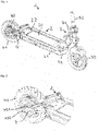
- the electric scooter 1 selected as an exemplary embodiment comprises a step element 2, which is connected in a known manner via a lockable pivoting device 3 to a frame strut 31 in which a steering rod 32 is rotatably mounted, which is provided on one side with a front wheel 33 and on the opposite side with a handlebar (not shown). .
- the steering rod 32 can be pivoted via the lockable pivoting device 3 into a position that is essentially parallel to the stepping element 2 .
- the tread element 2 is connected to a rear wheel 41 at the rear via a rear wheel swing arm 4 .
- the rear wheel 41 is connected to an electric motor 42 which is fed via an accumulator 20 which is accommodated by the tread element 2 .
- the tread element 2 comprises two side profiles 21 which are connected to one another at their ends via a transverse profile 22 arranged between them.
- the side profiles 21 and the transverse profiles 22 are designed as hollow profiles with a substantially rectangular cross section.
- the rectangular frame formed by the side profiles 21 and the transverse profiles 22 is provided on its underside with a floor, not shown, on which the accumulator 20 is arranged. On its upper side, the frame is closed by a cover--not shown.
- the rear wheel swing arm 4 is essentially U-shaped and has two legs 43 arranged opposite one another, which end in an axle mount 432 for the rear wheel 41 .
- the rear wheel swing arm 4 has, on its side facing away from the legs 43, a stop part 44 with two spaced bushings 441, which are arranged on both sides of a bushing 23 present in the rear-side transverse profile 22 of the tread element 2, with which they can be connected via an axis guided through it 24 form a hinge via which the rear wheel swing arm 4 is pivotably connected to the transverse profile 22 of the tread element 2 .
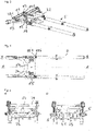
- a standpipe 5 is accommodated in each case by the side profiles 21 of the step element 2 , which is formed from a first partial pipe 51 and a second partial pipe 52 , which partial pipes 51 , 52 are connected via a connecting piece 53 .
- the partial pipes 51, 52 each have an internal thread at the end, with which you can each connect to an end on the connecting piece 53 External threads are screwed on.
- the connecting piece 53 has a smaller inner diameter than the partial tubes 51, 52, as a result of which stops 54 are formed in the standpipe 5.
- a shaft 6 is arranged, which is subdivided into three functional sections.
- a connecting cylinder 61 is formed by a first cylindrical section, which is adjoined by a second, diameter-enlarged section, which forms the first spring receptacle 62 .
- the first spring seat 62 merges into a third, diameter-reduced cylindrical section, which forms the push rod 63, on the end of which a threaded pin 64 is formed.
- the shaft 6 is slidably mounted with the connecting cylinder 61 in the connecting piece 53 designed as a hub, the first spring receptacle 62 resting against a stop 54 of the connecting piece 53 in a position in a stop position.
- the stops 54 are provided with a damping layer, which is formed from a thermoelastic plastic in the exemplary embodiment.
- a helical spring 65 which rests against the first spring receptacle 62 and a second spring receptacle 55 which rests against the helical spring 65 are pushed onto the push rod 63 .
- the second spring receptacle 55 is sleeve-shaped and has a spring cage 551 at the end, by which the helical spring 65 is accommodated.
- an external thread is introduced into the second spring receptacle 55 , with which it is screwed into an internal thread arranged at the end in the first partial tube 51 .
- the external thread is followed by a circumferential indentation, with which the second spring receptacle 55 penetrates a locking ring 56 which is attached to the end of the first partial tube 51 .
- the locking ring 56 is composed of two ring halves in the exemplary embodiment.
- the second spring receptacle 55 is provided with a tool engagement 552, which is formed by circumferentially arranged radial blind bores.
- An inside diameter enlarged section is arranged inside in the area of the tool engagement 552, which together with the the push rod 63 guided by the second spring receptacle 55 delimits an annular gap 57 .
- the prestressing of the helical spring 65 can be adjusted by rotating the second spring receptacle 55 .
- a scale 553 is introduced on the outside of the second spring receptacle 55 in front of the tool engagement 552, on which scale the respectively set spring preload can be read.
- a shock absorber 7 is introduced into the second partial tube 52 of the standpipe 5 , the cylinder 71 of which is fastened via a screw which is guided through a plug 58 closing the second partial tube 52 at the end.
- a piston 72 is slidably guided in the cylinder 71 of the shock absorber 7, the piston rod 73 of which is screwed with its external thread at the end into a threaded blind bore made at the free end of the connecting cylinder 61 of the shaft 6, as a result of which the piston rod 73 is connected to the shaft 6.
- a snap ring 611 is fastened on the outside of the connecting cylinder 61, which in a stop position of the connecting cylinder 61 bears against the stop 54 of the connecting piece 53 facing it.
- the axial movement of the connecting cylinder 61 in the connecting piece 53 designed as a hub is thus limited on the one hand by the first spring mount 61 and on the other hand by the snap ring 611 .
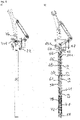
- the two toggle levers 8 are each formed by two levers 81, 82 which are pivotably connected to one another.
- the first, longer lever 81 is pivotally connected at its first end to a U-shaped bracket 431 arranged on the respective arm 43 of the rear wheel swing arm 4, in which it engages and is connected to it via an axle bolt 83.
- the second end of the first lever 81 is in turn connected to the second, shorter lever 82 via an axle bolt 83 .
- the second lever 82 has a slot-shaped recess 821 in which the first lever 81 engages.
- the second lever 82 of the two toggle levers 8 are provided with a passage through which one end of a common axle shaft 84 is guided and through which the two toggle levers 8 are connected to one another.
- the axle shaft 84 is rotatably mounted in two spaced-apart bushings 24 fastened on the rear-side transverse profile 22 .
- a connecting piece 85 is pivotably attached, which has a screw sleeve 851 which is screwed onto the threaded pin 64 of the shaft 6 of the associated standpipe 5.
- the screw sleeve 851 is accommodated in a stop position by the annular gap 57 delimited between the section of the second spring receptacle 55 with the enlarged inner diameter and the push rod 63 guided through it.
Landscapes
- Engineering & Computer Science (AREA)
- Mechanical Engineering (AREA)
- Axle Suspensions And Sidecars For Cycles (AREA)
Priority Applications (2)
| Application Number | Priority Date | Filing Date | Title |
|---|---|---|---|
| EP21158693.8A EP4046899B1 (fr) | 2021-02-23 | 2021-02-23 | Trottinette, en particulier trottinette électrique |
| PCT/EP2022/053156 WO2022179853A1 (fr) | 2021-02-23 | 2022-02-09 | Trottinette, en particulier trottinette électrique |
Applications Claiming Priority (1)
| Application Number | Priority Date | Filing Date | Title |
|---|---|---|---|
| EP21158693.8A EP4046899B1 (fr) | 2021-02-23 | 2021-02-23 | Trottinette, en particulier trottinette électrique |
Publications (2)
| Publication Number | Publication Date |
|---|---|
| EP4046899A1 true EP4046899A1 (fr) | 2022-08-24 |
| EP4046899B1 EP4046899B1 (fr) | 2023-02-22 |
Family
ID=74732599
Family Applications (1)
| Application Number | Title | Priority Date | Filing Date |
|---|---|---|---|
| EP21158693.8A Active EP4046899B1 (fr) | 2021-02-23 | 2021-02-23 | Trottinette, en particulier trottinette électrique |
Country Status (2)
| Country | Link |
|---|---|
| EP (1) | EP4046899B1 (fr) |
| WO (1) | WO2022179853A1 (fr) |
Cited By (1)
| Publication number | Priority date | Publication date | Assignee | Title |
|---|---|---|---|---|
| FR3152484A1 (fr) * | 2023-09-06 | 2025-03-07 | Cochet | Dispositif de suspension arrière de trottinette et trottinette équipée d’un tel dispositif |
Citations (13)
| Publication number | Priority date | Publication date | Assignee | Title |
|---|---|---|---|---|
| KR200175479Y1 (ko) * | 1999-10-08 | 2000-03-15 | 주식회사델타모페드 | 서행용 이륜차의 충격흡수장치 |
| KR20010036533A (ko) * | 1999-10-08 | 2001-05-07 | 김암규 | 서행용 이륜차의 충격흡수장치 |
| CN2452878Y (zh) * | 2000-12-05 | 2001-10-10 | 信隆实业(深圳)有限公司 | 滑板车后轮减震机构 |
| CN2457021Y (zh) * | 2000-11-24 | 2001-10-31 | 陈定兴 | 滑板车避震装置 |
| US6406042B1 (en) * | 2000-10-10 | 2002-06-18 | Shui-Te Tsai | Kick scooter |
| US20030213633A1 (en) * | 2002-05-16 | 2003-11-20 | Patmont Motor Werks | Scooter with Integral Frame Mounted Shock Absorber |
| EP2425989A1 (fr) | 2010-09-01 | 2012-03-07 | Dijiya Energy Saving Technology Inc. | Roue intégrée et scooter électrique l'utilisant |
| CN202879720U (zh) * | 2012-09-21 | 2013-04-17 | 杨莲传 | 滑板车的后避震器结构 |
| US20160137257A1 (en) * | 2014-11-18 | 2016-05-19 | Zhejiang Freedare Sports Equipment Co., Ltd. | Concealed rear wheel suspension device for a scooter |
| CN206734537U (zh) * | 2017-03-31 | 2017-12-12 | 纳恩博(北京)科技有限公司 | 减震组件及滑板车 |
| WO2019149024A1 (fr) * | 2018-01-30 | 2019-08-08 | 深圳市多彩实业有限公司 | Trottinette électrique à structure de suspension |
| WO2019156285A1 (fr) * | 2018-02-09 | 2019-08-15 | 연제혁 | Scooter électrique |
| DE202021100072U1 (de) * | 2021-01-08 | 2021-01-28 | Anita Wu | Zusammenklappbarer Motorroller |
-
2021
- 2021-02-23 EP EP21158693.8A patent/EP4046899B1/fr active Active
-
2022
- 2022-02-09 WO PCT/EP2022/053156 patent/WO2022179853A1/fr not_active Ceased
Patent Citations (13)
| Publication number | Priority date | Publication date | Assignee | Title |
|---|---|---|---|---|
| KR200175479Y1 (ko) * | 1999-10-08 | 2000-03-15 | 주식회사델타모페드 | 서행용 이륜차의 충격흡수장치 |
| KR20010036533A (ko) * | 1999-10-08 | 2001-05-07 | 김암규 | 서행용 이륜차의 충격흡수장치 |
| US6406042B1 (en) * | 2000-10-10 | 2002-06-18 | Shui-Te Tsai | Kick scooter |
| CN2457021Y (zh) * | 2000-11-24 | 2001-10-31 | 陈定兴 | 滑板车避震装置 |
| CN2452878Y (zh) * | 2000-12-05 | 2001-10-10 | 信隆实业(深圳)有限公司 | 滑板车后轮减震机构 |
| US20030213633A1 (en) * | 2002-05-16 | 2003-11-20 | Patmont Motor Werks | Scooter with Integral Frame Mounted Shock Absorber |
| EP2425989A1 (fr) | 2010-09-01 | 2012-03-07 | Dijiya Energy Saving Technology Inc. | Roue intégrée et scooter électrique l'utilisant |
| CN202879720U (zh) * | 2012-09-21 | 2013-04-17 | 杨莲传 | 滑板车的后避震器结构 |
| US20160137257A1 (en) * | 2014-11-18 | 2016-05-19 | Zhejiang Freedare Sports Equipment Co., Ltd. | Concealed rear wheel suspension device for a scooter |
| CN206734537U (zh) * | 2017-03-31 | 2017-12-12 | 纳恩博(北京)科技有限公司 | 减震组件及滑板车 |
| WO2019149024A1 (fr) * | 2018-01-30 | 2019-08-08 | 深圳市多彩实业有限公司 | Trottinette électrique à structure de suspension |
| WO2019156285A1 (fr) * | 2018-02-09 | 2019-08-15 | 연제혁 | Scooter électrique |
| DE202021100072U1 (de) * | 2021-01-08 | 2021-01-28 | Anita Wu | Zusammenklappbarer Motorroller |
Cited By (1)
| Publication number | Priority date | Publication date | Assignee | Title |
|---|---|---|---|---|
| FR3152484A1 (fr) * | 2023-09-06 | 2025-03-07 | Cochet | Dispositif de suspension arrière de trottinette et trottinette équipée d’un tel dispositif |
Also Published As
| Publication number | Publication date |
|---|---|
| WO2022179853A1 (fr) | 2022-09-01 |
| EP4046899B1 (fr) | 2023-02-22 |
Similar Documents
| Publication | Publication Date | Title |
|---|---|---|
| DE602004006018T2 (de) | Verstellbares gasfederaufhängungssystem | |
| DE69017920T2 (de) | Motorrad mit höhenverstellbarer Karosserie. | |
| EP3403910B1 (fr) | Dispositif de traction, en particulier pour une bicyclette | |
| DE2935300A1 (de) | Radaufhaengung fuer fahrzeuge | |
| DE19653148A1 (de) | Teleskopisch einfederbare Radführung | |
| EP3412928B1 (fr) | Dispositif d'amortissment traction, en particulier pour une bicyclette | |
| DE4123643A1 (de) | Fahrrad | |
| EP3009708B1 (fr) | Amortisseur d'oscillations avec amortissement autonome reglable pour le palier de pression et le palier de traction | |
| EP1238900B1 (fr) | Cadre de bicyclette | |
| DE4117460C2 (de) | Steuervorrichtung zum variablen Einstellen der Dämpfungskraft von Schwingungsdämpfern | |
| DE102011013059B4 (de) | Fahrradfederungseinsteller | |
| EP4046899B1 (fr) | Trottinette, en particulier trottinette électrique | |
| DE202021000494U1 (de) | Einklappbarer Lenker | |
| EP4019381B1 (fr) | Barre de direction pour véhicule à deux roues | |
| EP1964695B1 (fr) | Unité d'amortissement et de ressort à air avec élément de commande | |
| EP3552940B1 (fr) | Dispositif de direction d'un deux-roues, en particulier d'une bicyclette dotée d'une suspension avant | |
| DE4116814C1 (en) | Motorcycle handlebar with two vibratory arms - de4119125 coupled by sprung and damped housing with two separate chambers, each with two absorbers | |
| DE202021100890U1 (de) | Roller, insbesondere Elektroroller | |
| EP4019379B1 (fr) | Guidon repliable | |
| DE202020107471U1 (de) | Lenkstange für Zweiräder | |
| DE102024124210A1 (de) | Dämpfungseinrichtung für ein Fahrrad | |
| DE4427409A1 (de) | Fahrrad | |
| DE20105369U1 (de) | Federnde Sattelstütze | |
| DE102024124214A1 (de) | Dämpfungseinrichtung für ein Fahrrad | |
| DE102024124217A1 (de) | Dämpfungseinrichtung für ein Fahrrad |
Legal Events
| Date | Code | Title | Description |
|---|---|---|---|
| STAA | Information on the status of an ep patent application or granted ep patent |
Free format text: STATUS: EXAMINATION IS IN PROGRESS |
|
| PUAI | Public reference made under article 153(3) epc to a published international application that has entered the european phase |
Free format text: ORIGINAL CODE: 0009012 |
|
| 17P | Request for examination filed |
Effective date: 20211004 |
|
| AK | Designated contracting states |
Kind code of ref document: A1 Designated state(s): AL AT BE BG CH CY CZ DE DK EE ES FI FR GB GR HR HU IE IS IT LI LT LU LV MC MK MT NL NO PL PT RO RS SE SI SK SM TR |
|
| GRAP | Despatch of communication of intention to grant a patent |
Free format text: ORIGINAL CODE: EPIDOSNIGR1 |
|
| STAA | Information on the status of an ep patent application or granted ep patent |
Free format text: STATUS: GRANT OF PATENT IS INTENDED |
|
| INTG | Intention to grant announced |
Effective date: 20221017 |
|
| GRAS | Grant fee paid |
Free format text: ORIGINAL CODE: EPIDOSNIGR3 |
|
| GRAA | (expected) grant |
Free format text: ORIGINAL CODE: 0009210 |
|
| STAA | Information on the status of an ep patent application or granted ep patent |
Free format text: STATUS: THE PATENT HAS BEEN GRANTED |
|
| AK | Designated contracting states |
Kind code of ref document: B1 Designated state(s): AL AT BE BG CH CY CZ DE DK EE ES FI FR GB GR HR HU IE IS IT LI LT LU LV MC MK MT NL NO PL PT RO RS SE SI SK SM TR |
|
| REG | Reference to a national code |
Ref country code: GB Ref legal event code: FG4D Free format text: NOT ENGLISH |
|
| REG | Reference to a national code |
Ref country code: CH Ref legal event code: EP |
|
| REG | Reference to a national code |
Ref country code: DE Ref legal event code: R096 Ref document number: 502021000444 Country of ref document: DE |
|
| REG | Reference to a national code |
Ref country code: AT Ref legal event code: REF Ref document number: 1549343 Country of ref document: AT Kind code of ref document: T Effective date: 20230315 Ref country code: IE Ref legal event code: FG4D Free format text: LANGUAGE OF EP DOCUMENT: GERMAN |
|
| REG | Reference to a national code |
Ref country code: LT Ref legal event code: MG9D |
|
| P01 | Opt-out of the competence of the unified patent court (upc) registered |
Effective date: 20230425 |
|
| REG | Reference to a national code |
Ref country code: NL Ref legal event code: MP Effective date: 20230222 |
|
| PG25 | Lapsed in a contracting state [announced via postgrant information from national office to epo] |
Ref country code: RS Free format text: LAPSE BECAUSE OF FAILURE TO SUBMIT A TRANSLATION OF THE DESCRIPTION OR TO PAY THE FEE WITHIN THE PRESCRIBED TIME-LIMIT Effective date: 20230222 Ref country code: PT Free format text: LAPSE BECAUSE OF FAILURE TO SUBMIT A TRANSLATION OF THE DESCRIPTION OR TO PAY THE FEE WITHIN THE PRESCRIBED TIME-LIMIT Effective date: 20230622 Ref country code: NO Free format text: LAPSE BECAUSE OF FAILURE TO SUBMIT A TRANSLATION OF THE DESCRIPTION OR TO PAY THE FEE WITHIN THE PRESCRIBED TIME-LIMIT Effective date: 20230522 Ref country code: NL Free format text: LAPSE BECAUSE OF FAILURE TO SUBMIT A TRANSLATION OF THE DESCRIPTION OR TO PAY THE FEE WITHIN THE PRESCRIBED TIME-LIMIT Effective date: 20230222 Ref country code: LV Free format text: LAPSE BECAUSE OF FAILURE TO SUBMIT A TRANSLATION OF THE DESCRIPTION OR TO PAY THE FEE WITHIN THE PRESCRIBED TIME-LIMIT Effective date: 20230222 Ref country code: LT Free format text: LAPSE BECAUSE OF FAILURE TO SUBMIT A TRANSLATION OF THE DESCRIPTION OR TO PAY THE FEE WITHIN THE PRESCRIBED TIME-LIMIT Effective date: 20230222 Ref country code: HR Free format text: LAPSE BECAUSE OF FAILURE TO SUBMIT A TRANSLATION OF THE DESCRIPTION OR TO PAY THE FEE WITHIN THE PRESCRIBED TIME-LIMIT Effective date: 20230222 Ref country code: ES Free format text: LAPSE BECAUSE OF FAILURE TO SUBMIT A TRANSLATION OF THE DESCRIPTION OR TO PAY THE FEE WITHIN THE PRESCRIBED TIME-LIMIT Effective date: 20230222 |
|
| PG25 | Lapsed in a contracting state [announced via postgrant information from national office to epo] |
Ref country code: SE Free format text: LAPSE BECAUSE OF FAILURE TO SUBMIT A TRANSLATION OF THE DESCRIPTION OR TO PAY THE FEE WITHIN THE PRESCRIBED TIME-LIMIT Effective date: 20230222 Ref country code: PL Free format text: LAPSE BECAUSE OF FAILURE TO SUBMIT A TRANSLATION OF THE DESCRIPTION OR TO PAY THE FEE WITHIN THE PRESCRIBED TIME-LIMIT Effective date: 20230222 Ref country code: IS Free format text: LAPSE BECAUSE OF FAILURE TO SUBMIT A TRANSLATION OF THE DESCRIPTION OR TO PAY THE FEE WITHIN THE PRESCRIBED TIME-LIMIT Effective date: 20230622 Ref country code: GR Free format text: LAPSE BECAUSE OF FAILURE TO SUBMIT A TRANSLATION OF THE DESCRIPTION OR TO PAY THE FEE WITHIN THE PRESCRIBED TIME-LIMIT Effective date: 20230523 Ref country code: FI Free format text: LAPSE BECAUSE OF FAILURE TO SUBMIT A TRANSLATION OF THE DESCRIPTION OR TO PAY THE FEE WITHIN THE PRESCRIBED TIME-LIMIT Effective date: 20230222 |
|
| REG | Reference to a national code |
Ref country code: BE Ref legal event code: MM Effective date: 20230228 |
|
| PG25 | Lapsed in a contracting state [announced via postgrant information from national office to epo] |
Ref country code: SM Free format text: LAPSE BECAUSE OF FAILURE TO SUBMIT A TRANSLATION OF THE DESCRIPTION OR TO PAY THE FEE WITHIN THE PRESCRIBED TIME-LIMIT Effective date: 20230222 Ref country code: RO Free format text: LAPSE BECAUSE OF FAILURE TO SUBMIT A TRANSLATION OF THE DESCRIPTION OR TO PAY THE FEE WITHIN THE PRESCRIBED TIME-LIMIT Effective date: 20230222 Ref country code: LU Free format text: LAPSE BECAUSE OF NON-PAYMENT OF DUE FEES Effective date: 20230223 Ref country code: EE Free format text: LAPSE BECAUSE OF FAILURE TO SUBMIT A TRANSLATION OF THE DESCRIPTION OR TO PAY THE FEE WITHIN THE PRESCRIBED TIME-LIMIT Effective date: 20230222 Ref country code: DK Free format text: LAPSE BECAUSE OF FAILURE TO SUBMIT A TRANSLATION OF THE DESCRIPTION OR TO PAY THE FEE WITHIN THE PRESCRIBED TIME-LIMIT Effective date: 20230222 Ref country code: CZ Free format text: LAPSE BECAUSE OF FAILURE TO SUBMIT A TRANSLATION OF THE DESCRIPTION OR TO PAY THE FEE WITHIN THE PRESCRIBED TIME-LIMIT Effective date: 20230222 |
|
| REG | Reference to a national code |
Ref country code: DE Ref legal event code: R097 Ref document number: 502021000444 Country of ref document: DE |
|
| PG25 | Lapsed in a contracting state [announced via postgrant information from national office to epo] |
Ref country code: SK Free format text: LAPSE BECAUSE OF FAILURE TO SUBMIT A TRANSLATION OF THE DESCRIPTION OR TO PAY THE FEE WITHIN THE PRESCRIBED TIME-LIMIT Effective date: 20230222 |
|
| REG | Reference to a national code |
Ref country code: IE Ref legal event code: MM4A |
|
| PLBE | No opposition filed within time limit |
Free format text: ORIGINAL CODE: 0009261 |
|
| STAA | Information on the status of an ep patent application or granted ep patent |
Free format text: STATUS: NO OPPOSITION FILED WITHIN TIME LIMIT |
|
| PG25 | Lapsed in a contracting state [announced via postgrant information from national office to epo] |
Ref country code: MC Free format text: LAPSE BECAUSE OF FAILURE TO SUBMIT A TRANSLATION OF THE DESCRIPTION OR TO PAY THE FEE WITHIN THE PRESCRIBED TIME-LIMIT Effective date: 20230222 |
|
| 26N | No opposition filed |
Effective date: 20231123 |
|
| PG25 | Lapsed in a contracting state [announced via postgrant information from national office to epo] |
Ref country code: SI Free format text: LAPSE BECAUSE OF FAILURE TO SUBMIT A TRANSLATION OF THE DESCRIPTION OR TO PAY THE FEE WITHIN THE PRESCRIBED TIME-LIMIT Effective date: 20230222 Ref country code: MC Free format text: LAPSE BECAUSE OF FAILURE TO SUBMIT A TRANSLATION OF THE DESCRIPTION OR TO PAY THE FEE WITHIN THE PRESCRIBED TIME-LIMIT Effective date: 20230222 Ref country code: IE Free format text: LAPSE BECAUSE OF NON-PAYMENT OF DUE FEES Effective date: 20230223 Ref country code: FR Free format text: LAPSE BECAUSE OF NON-PAYMENT OF DUE FEES Effective date: 20230422 |
|
| PG25 | Lapsed in a contracting state [announced via postgrant information from national office to epo] |
Ref country code: BE Free format text: LAPSE BECAUSE OF NON-PAYMENT OF DUE FEES Effective date: 20230228 |
|
| PG25 | Lapsed in a contracting state [announced via postgrant information from national office to epo] |
Ref country code: IT Free format text: LAPSE BECAUSE OF FAILURE TO SUBMIT A TRANSLATION OF THE DESCRIPTION OR TO PAY THE FEE WITHIN THE PRESCRIBED TIME-LIMIT Effective date: 20230222 |
|
| REG | Reference to a national code |
Ref country code: CH Ref legal event code: PL |
|
| PG25 | Lapsed in a contracting state [announced via postgrant information from national office to epo] |
Ref country code: CH Free format text: LAPSE BECAUSE OF NON-PAYMENT OF DUE FEES Effective date: 20240229 |
|
| PG25 | Lapsed in a contracting state [announced via postgrant information from national office to epo] |
Ref country code: CH Free format text: LAPSE BECAUSE OF NON-PAYMENT OF DUE FEES Effective date: 20240229 |
|
| PG25 | Lapsed in a contracting state [announced via postgrant information from national office to epo] |
Ref country code: BG Free format text: LAPSE BECAUSE OF FAILURE TO SUBMIT A TRANSLATION OF THE DESCRIPTION OR TO PAY THE FEE WITHIN THE PRESCRIBED TIME-LIMIT Effective date: 20230222 |
|
| PG25 | Lapsed in a contracting state [announced via postgrant information from national office to epo] |
Ref country code: BG Free format text: LAPSE BECAUSE OF FAILURE TO SUBMIT A TRANSLATION OF THE DESCRIPTION OR TO PAY THE FEE WITHIN THE PRESCRIBED TIME-LIMIT Effective date: 20230222 |
|
| PGFP | Annual fee paid to national office [announced via postgrant information from national office to epo] |
Ref country code: AT Payment date: 20250417 Year of fee payment: 5 |
|
| PG25 | Lapsed in a contracting state [announced via postgrant information from national office to epo] |
Ref country code: CY Free format text: LAPSE BECAUSE OF FAILURE TO SUBMIT A TRANSLATION OF THE DESCRIPTION OR TO PAY THE FEE WITHIN THE PRESCRIBED TIME-LIMIT; INVALID AB INITIO Effective date: 20210223 |
|
| PG25 | Lapsed in a contracting state [announced via postgrant information from national office to epo] |
Ref country code: HU Free format text: LAPSE BECAUSE OF FAILURE TO SUBMIT A TRANSLATION OF THE DESCRIPTION OR TO PAY THE FEE WITHIN THE PRESCRIBED TIME-LIMIT; INVALID AB INITIO Effective date: 20210223 |
|
| REG | Reference to a national code |
Ref country code: DE Ref legal event code: R084 Ref document number: 502021000444 Country of ref document: DE |
|
| GBPC | Gb: european patent ceased through non-payment of renewal fee |
Effective date: 20250223 |
|
| PG25 | Lapsed in a contracting state [announced via postgrant information from national office to epo] |
Ref country code: TR Free format text: LAPSE BECAUSE OF FAILURE TO SUBMIT A TRANSLATION OF THE DESCRIPTION OR TO PAY THE FEE WITHIN THE PRESCRIBED TIME-LIMIT Effective date: 20230222 |
|
| PG25 | Lapsed in a contracting state [announced via postgrant information from national office to epo] |
Ref country code: GB Free format text: LAPSE BECAUSE OF NON-PAYMENT OF DUE FEES Effective date: 20250223 |
|
| PGFP | Annual fee paid to national office [announced via postgrant information from national office to epo] |
Ref country code: DE Payment date: 20260219 Year of fee payment: 6 |